JP2015114209A - Encoder and electromechanical device - Google Patents
Encoder and electromechanical device Download PDFInfo
- Publication number
- JP2015114209A JP2015114209A JP2013256557A JP2013256557A JP2015114209A JP 2015114209 A JP2015114209 A JP 2015114209A JP 2013256557 A JP2013256557 A JP 2013256557A JP 2013256557 A JP2013256557 A JP 2013256557A JP 2015114209 A JP2015114209 A JP 2015114209A
- Authority
- JP
- Japan
- Prior art keywords
- magnet body
- encoder
- axis
- magnetic
- magnetic sensor
- Prior art date
- Legal status (The legal status is an assumption and is not a legal conclusion. Google has not performed a legal analysis and makes no representation as to the accuracy of the status listed.)
- Pending
Links
Images

Landscapes
- Transmission And Conversion Of Sensor Element Output (AREA)
Abstract
Description
本発明は、磁気センサーを用いたエンコーダー、及び、それを用いた電気機械装置に関するものである。 The present invention relates to an encoder using a magnetic sensor and an electromechanical device using the encoder.
磁気センサーを用いたエンコーダーとしては、特許文献1に記載されたロータリーエンコーダーが知られている。ロータリーエンコーダーの回転体には、その中心に第1マグネットが設けられ、外周側には環状の複数の第2マグネットが設けられている。また、回転体に対向する固定体には、第1マグネットの磁場を検出する第1感磁素子と、第2マグネットの磁場を検出する第2感磁素子とが設けられている。第1感磁素子と第2感磁素子のそれぞれは、互いに直交する方向に設けられた2つの磁気抵抗パターンで構成されている。磁気抵抗パターンで磁場を適切に検出するために、第1マグネット及び第2マグネットは、感磁素子に向かう方向(すなわち回転軸に平行な方向)に沿って着磁されており、その着磁面(着磁方向と直交する面)が感磁素子に対向するように配置されている。但し、これらの第1感磁素子と第2感磁素子では、絶対的な回転角度を検出することができない。そこで、絶対的な回転角度を検出するために、固定体の上に、90度の角度で配置された2つのホール素子が設けられている。
As an encoder using a magnetic sensor, a rotary encoder described in
しかし、上述した従来のエンコーダーでは、磁気抵抗パターンを用いて磁場を検出しているので、磁気抵抗パターンの抵抗の精度によって回転角度の検出精度が制限される。一般に、磁気抵抗パターンの抵抗の精度を高めることは困難である。そこで、より高精度に回転角度を検出することのできる技術が望まれていた。また、回転角度に限らず、一般に、高精度に位置を検出することのできるエンコーダーが望まれていた。更に、電気機械装置に関しても、エンコーダーを用いて高精度に位置検出を行うことを可能とする技術が望まれていた。 However, in the conventional encoder described above, since the magnetic field is detected using the magnetoresistive pattern, the detection accuracy of the rotation angle is limited by the accuracy of the resistance of the magnetoresistive pattern. In general, it is difficult to increase the accuracy of the resistance of the magnetoresistive pattern. Therefore, a technique capable of detecting the rotation angle with higher accuracy has been desired. Further, not only the rotation angle but generally an encoder capable of detecting a position with high accuracy has been desired. Furthermore, regarding an electromechanical device, a technique that enables highly accurate position detection using an encoder has been desired.
本発明は、上述の課題の少なくとも一部を解決するためになされたものであり、以下の形態として実現することが可能である。 SUMMARY An advantage of some aspects of the invention is to solve at least a part of the problems described above, and the invention can be implemented as the following forms.
(1)本発明の一形態によれば、第1部材に対して所定の移動方向に沿って移動する第2部材の位置を測定するエンコーダーが提供される。このエンコーダーは、前記第2部材に設けられ、前記移動方向と交差する方向に着磁されたM1極(M1は4以上の偶数)の第1磁石体と;前記第2部材に設けられ、前記移動方向と交差する方向に着磁されたM2極(M2は2以上の偶数)の第2磁石体と;前記第1磁石体の表面から一定のギャップを有して、前記第1部材上に配置された第1の2軸磁気センサー回路と;前記第2磁石体の表面から一定のギャップを有して、前記第1部材上に配置された第2の2軸磁気センサー回路と;前記第1の2軸磁気センサー回路と前記第2の2軸磁気センサー回路の出力信号を処理する位置信号生成部と;を備える。前記位置信号生成部は、前記第1の2軸磁気センサー回路の第1磁気角出力と、前記第2の2軸磁気センサー回路の第2磁気角出力とに応じて、前記第1部材に対する前記第2部材の位置を示す位置信号を生成する。
このエンコーダーによれば、2軸磁気センサー回路を用いているので、精度良く位置検出を行うことが可能である。また、位置信号生成部は、第1の2軸磁気センサー回路の第1磁気角出力と第2の2軸磁気センサー回路の第2磁気角出力とに応じて位置信号を生成するので、1つの2軸磁気センサー回路を用いる場合に比べて更に高精度に位置検出を行うことができる。
(1) According to one form of this invention, the encoder which measures the position of the 2nd member which moves along a predetermined | prescribed movement direction with respect to a 1st member is provided. The encoder is provided in the second member, and is provided in the second member; a first magnet body having an M1 pole (M1 is an even number of 4 or more) magnetized in a direction crossing the moving direction; A second magnet body having M2 poles (M2 is an even number of 2 or more) magnetized in a direction crossing the moving direction; and having a certain gap from the surface of the first magnet body, on the first member A first biaxial magnetic sensor circuit disposed; a second biaxial magnetic sensor circuit disposed on the first member with a certain gap from a surface of the second magnet body; A two-axis magnetic sensor circuit and a position signal generation unit that processes an output signal of the second two-axis magnetic sensor circuit. The position signal generator is configured to output the first member with respect to the first member according to a first magnetic angle output of the first two-axis magnetic sensor circuit and a second magnetic angle output of the second two-axis magnetic sensor circuit. A position signal indicating the position of the second member is generated.
According to this encoder, since a biaxial magnetic sensor circuit is used, position detection can be performed with high accuracy. The position signal generation unit generates a position signal according to the first magnetic angle output of the first two-axis magnetic sensor circuit and the second magnetic angle output of the second two-axis magnetic sensor circuit. Position detection can be performed with higher accuracy than in the case of using a biaxial magnetic sensor circuit.
(2)上記エンコーダーにおいて、前記第1の2軸磁気センサー回路と前記第2の2軸磁気センサー回路のそれぞれは、互いに直交するX軸とY軸のうちの前記X軸に沿った磁場を測定するための複数個のX軸センサー素子と、前記Y軸に沿った磁場を測定するための複数個のY軸センサ素子と、を含むものとしてもよい。
この構成によれば、2軸磁気センサー回路の複数のホール素子の出力として、磁気歪みの少ない正弦波状の出力を得ることができ、これらの磁気歪みの少ない正弦波状出力に基づいて精度良く位置検出を行うことが可能である。
(2) In the encoder, each of the first two-axis magnetic sensor circuit and the second two-axis magnetic sensor circuit measures a magnetic field along the X axis of the X axis and the Y axis orthogonal to each other. A plurality of X-axis sensor elements for measuring, and a plurality of Y-axis sensor elements for measuring a magnetic field along the Y-axis.
According to this configuration, it is possible to obtain a sine wave-like output with less magnetostriction as the output of a plurality of Hall elements of the two-axis magnetic sensor circuit, and accurately detect the position based on these sine wave-like outputs with little magnetostriction. Can be done.
(3)上記エンコーダーにおいて、前記整数M1,M2は、M1/2とM2/2が互いに素となる整数であり、前記位置信号生成部は、前記第1の2軸磁気センサーの第1磁気角出力と前記第2の2軸磁気センサーの第2磁気角出力から前記位置信号を生成するものとしてもよい。
この構成によれば、第1の2軸磁気センサーの第1磁気角出力と第2の2軸磁気センサーの第2磁気角出力から、第1部材に対する第2部材の位置を高精度に検出可能である。
(3) In the encoder, the integers M1 and M2 are integers in which M1 / 2 and M2 / 2 are prime, and the position signal generation unit is configured to output a first magnetic angle of the first biaxial magnetic sensor. The position signal may be generated from an output and a second magnetic angle output of the second two-axis magnetic sensor.
According to this configuration, the position of the second member relative to the first member can be detected with high accuracy from the first magnetic angle output of the first two-axis magnetic sensor and the second magnetic angle output of the second two-axis magnetic sensor. It is.
(4)上記エンコーダーにおいて、前記整数M1は、2Q+1(Qは1以上の整数)に等しく、前記整数M2は、2に等しく、前記第1の2軸磁気センサー回路の第1磁気角出力は、前記第1部材に対する前記第2部材の相対位置を示すN1ビット(N1は2以上の整数)のデジタル信号であり、前記第2の2軸磁気センサー回路の第2磁気角出力は、前記第1部材に対する前記第2部材の相対位置を示すN2ビット(N2は2以上の整数)のデジタル信号であり、前記位置信号生成部は、前記第2磁気角出力の最上位Qビットを最上位に配置するとともに、前記第1磁気角出力のN1ビットを前記第2磁気角出力の前記最上位Qビットの下に配置した(N1+Q)ビットの信号を前記位置信号として生成するものとしてもよい。
この構成によれば、第2磁気角出力の最上位Qビットと、第1磁気角出力のN1ビットとを組み合わせることによって位置信号のビット数を増加できるので、高精度(高分解能)の位置検出が可能である。
(4) In the encoder, the integer M1 is equal to 2 Q + 1 (Q is an integer of 1 or more), the integer M2 is equal to 2, and the first magnetic angle of the first two-axis magnetic sensor circuit The output is a digital signal of N1 bits (N1 is an integer of 2 or more) indicating the relative position of the second member with respect to the first member, and the second magnetic angle output of the second biaxial magnetic sensor circuit is: The digital signal of N2 bits (N2 is an integer of 2 or more) indicating the relative position of the second member with respect to the first member, and the position signal generation unit outputs the most significant Q bit of the second magnetic angle output It is also possible to generate a (N1 + Q) -bit signal as the position signal in which the N1 bit of the first magnetic angle output is arranged below the most significant Q bit of the second magnetic angle output. .
According to this configuration, since the number of bits of the position signal can be increased by combining the most significant Q bit of the second magnetic angle output and the N1 bit of the first magnetic angle output, position detection with high accuracy (high resolution) Is possible.
(5)上記エンコーダーにおいて、前記位置信号生成部は、前記第2の部材の移動に応じて前記第1の2軸磁気センサー回路の前記第1磁気角出力と前記第2の2軸磁気センサー回路の前記第2磁気角出力とがともに増加する際に、前記第1磁気角出力が前記第1磁気角出力の最大値から最小値に戻るタイミングと、前記第2磁気角出力の前記最上位Qビットがインクリメントするタイミングとが一致するように、前記第1磁気角出力に応じて前記第2磁気角出力の前記最上位Qビットを補正し、前記補正後の前記第2磁気角出力の前記最上位Qビットを用いて、前記(N1+Q)ビットの前記位置信号を生成するものとしてもよい。
この構成によれば、第2磁気角出力に無視できない程度の誤差が存在する場合にも、第2磁気角出力の最上位Qビットと第1磁気角出力のN1ビットとを組み合わせることによって、正しい位置信号を得ることが可能である。
(5) In the encoder, the position signal generation unit includes the first magnetic angle output of the first two-axis magnetic sensor circuit and the second two-axis magnetic sensor circuit according to the movement of the second member. When the first magnetic angle output of the second magnetic angle output increases, the timing at which the first magnetic angle output returns from the maximum value of the first magnetic angle output to the minimum value, and the highest Q of the second magnetic angle output. The most significant Q bit of the second magnetic angle output is corrected in accordance with the first magnetic angle output so that the timing at which the bit is incremented, and the highest magnetic bit output of the second magnetic angle output after the correction is corrected. The position signal of the (N1 + Q) bits may be generated using the upper Q bits.
According to this configuration, even when there is a non-negligible error in the second magnetic angle output, the combination of the most significant Q bit of the second magnetic angle output and the N1 bit of the first magnetic angle output is correct. A position signal can be obtained.
(6)上記エンコーダーにおいて、前記第2部材は、回転体であり、前記磁石体を構成する個々の小磁石は、前記第1部材と前記第2部材の対向方向と垂直な着磁方向であって前記個々の小磁石の中心と前記回転体の回転軸とを結ぶ方向に平行な着磁方向に沿って平行着磁されている、ものとしてもよい。
この構成によれば、平行着磁された磁石の磁場を2軸磁気センサー回路のホール素子で検出することによって、磁気歪みの少ない正弦波状の出力を得ることが可能である。
(6) In the encoder, the second member is a rotating body, and each small magnet constituting the magnet body has a magnetization direction perpendicular to a facing direction of the first member and the second member. The magnets may be magnetized in parallel along a magnetization direction parallel to a direction connecting the centers of the individual small magnets and the rotation axis of the rotating body.
According to this configuration, it is possible to obtain a sinusoidal output with little magnetostriction by detecting the magnetic field of the magnets magnetized in parallel with the Hall element of the two-axis magnetic sensor circuit.
(7)上記エンコーダーにおいて、前記第2部材は、前記磁石体の内周と外周の少なくとも一方に設けられた環状のヨーク部材を有し、前記2軸磁気センサー回路は、前記第2部材の径方向に沿って測った磁束密度で0となる磁束中心部を外した位置に配置されていることが好ましい。
この構成によれば、2軸磁気センサー回路の位置検出誤差をより低減できる。
(7) In the encoder, the second member has an annular yoke member provided on at least one of an inner periphery and an outer periphery of the magnet body, and the biaxial magnetic sensor circuit has a diameter of the second member. It is preferable that the magnetic flux density measured along the direction is arranged at a position where the magnetic flux central portion that becomes 0 is removed.
According to this configuration, the position detection error of the biaxial magnetic sensor circuit can be further reduced.
(8)上記エンコーダーにおいて、前記第1磁石体は、複数の分割磁石体を円環状に並べることによって構成されており、各分割磁石体は、直方体形状を有する小磁石と、前記小磁石の周囲の少なくとも一部を被覆することによって前記分割磁石体の全体の形状を等辺台形柱形状とする被覆部材と、を有する、ものとしてもよい。
この構成によれば、極めて多極の磁石体を用いた位置精度の高いエンコーダーを容易に作成することが可能である。
(8) In the encoder, the first magnet body is configured by arranging a plurality of divided magnet bodies in an annular shape, and each divided magnet body includes a small magnet having a rectangular parallelepiped shape, and a periphery of the small magnet It is good also as what has a covering member which makes the whole shape of the said division | segmentation magnet body an isosceles trapezoid pillar shape by coat | covering at least one part.
According to this configuration, it is possible to easily create an encoder with high positional accuracy using an extremely multipolar magnet body.
(9)本発明の他の形態によれば、電気機械装置が提供される。この電気機械装置は、駆動又は回生用の磁石体と、駆動又は回生用の電磁コイルと、上記エンコーダーと、前記電気機械装置の動作を制御する制御部と、を備え、前記駆動又は回生用の磁石体が、前記エンコーダーの前記第1磁石体として共用される。
この電気機械装置によれば、電気機械装置の駆動又は回生用の磁石体と、エンコーダーの磁石体を共用するので、電気機械装置とエンコーダーの全体の構造を簡略化しつつ、高精度に電気機械装置の磁石体の位置検出を行うことが可能である。
(9) According to another aspect of the invention, an electromechanical device is provided. The electromechanical device includes a drive or regenerative magnet body, a drive or regenerative electromagnetic coil, the encoder, and a control unit that controls the operation of the electromechanical device. A magnet body is shared as the first magnet body of the encoder.
According to this electromechanical device, since the magnet body for driving or regenerating the electromechanical device and the magnet body of the encoder are shared, the overall structure of the electromechanical device and the encoder is simplified and the electromechanical device is highly accurate. It is possible to detect the position of the magnet body.
(10)上記電気機械装置は、2相の電磁コイルを有するDCモーターであり、前記制御部は、前記エンコーダーの前記第1の2軸磁気センサー回路から出力される前記正弦波信号及び前記余弦波信号から、前記2相の電磁コイルの駆動信号を生成する駆動信号生成部を有する、ものとしてもよい。
この構成によれば、1つの2軸磁気センサー回路から出力される正弦波信号及び前記余弦波信号から2相の駆動信号を生成するので、磁気センサーの位置ズレなどに起因する駆動信号の位相ズレを防止することが可能である。
(10) The electromechanical device is a DC motor having a two-phase electromagnetic coil, and the control unit is configured to output the sine wave signal and the cosine wave output from the first two-axis magnetic sensor circuit of the encoder. A drive signal generation unit that generates a drive signal for the two-phase electromagnetic coil from the signal may be provided.
According to this configuration, since the two-phase drive signal is generated from the sine wave signal and the cosine wave signal output from one two-axis magnetic sensor circuit, the phase shift of the drive signal due to the position shift of the magnetic sensor or the like. Can be prevented.
(11)本発明の更に他の形態によれば、電気機械装置が提供される。この電気機械装置は、2相のDCモーターとして動作可能な電気機械装置であって、磁石体と、2相の電磁コイルと、上記エンコーダーと、前記電気機械装置の動作を制御する制御部と、を備え、前記制御部は、前記エンコーダーの前記第1の2軸磁気センサー回路から出力される前記正弦波信号及び前記余弦波信号から、前記2相の電磁コイルの駆動信号を生成する駆動信号生成部を有する。
この電気機械装置によれば、1つの2軸磁気センサー回路から出力される正弦波信号及び前記余弦波信号から2相の駆動信号を生成するので、磁気センサーの位置ズレなどに起因する駆動信号の位相ズレを防止することが可能である。
(11) According to still another aspect of the present invention, an electromechanical device is provided. The electromechanical device is an electromechanical device operable as a two-phase DC motor, and includes a magnet body, a two-phase electromagnetic coil, the encoder, and a control unit that controls the operation of the electromechanical device; And the control unit generates a drive signal for the two-phase electromagnetic coil from the sine wave signal and the cosine wave signal output from the first two-axis magnetic sensor circuit of the encoder Part.
According to this electromechanical device, since the two-phase drive signal is generated from the sine wave signal and the cosine wave signal output from one two-axis magnetic sensor circuit, the drive signal caused by the positional deviation of the magnetic sensor is generated. It is possible to prevent a phase shift.
本発明は、装置以外の種々の形態で実現することも可能である。例えば、エンコーダー、ロータリーエンコーダー、位置検出方法、回転位置検出方法、エンコーダーを備えた電気機械装置、ロボット、鉄道車両、それらの方法又は装置の機能を実現するためのコンピュータープログラム、そのコンピュータープログラムを記録した一時的でない記録媒体(non-transitory storage medium)等の形態で実現することができる。 The present invention can be realized in various forms other than the apparatus. For example, an encoder, a rotary encoder, a position detection method, a rotational position detection method, an electromechanical device equipped with an encoder, a robot, a railway vehicle, a computer program for realizing the function of the method or device, and the computer program recorded It can be realized in the form of a non-transitory storage medium.
A.第1実施形態(1つの磁石体を用いたロータリーエンコーダー)
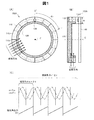
図1は、第1実施形態としてのロータリーエンコーダー100Aの構成と動作を示す説明図である。このロータリーエンコーダー100Aは、環状の磁石体110と、磁石体110の表面に対向して設けられた2軸磁気センサー回路130とを有している。2軸磁気センサー回路130は、基板140(図1(B))上に固定されている。基板140は回転しない固定体(「ステータ」又は「第1部材」とも呼ぶ)を構成し、磁石体110は回転体(「ロータ」又は「第2部材」とも呼ぶ)を構成している。この回転体は、仮想的な回転軸Cの回りに回転する。従って、回転体の移動方向は、磁石体110の周方向である。
A. First embodiment (rotary encoder using one magnet body)
FIG. 1 is an explanatory diagram showing the configuration and operation of a
磁石体110は8個の小磁石110sで構成されており、隣接する小磁石110s同士は逆向きに磁化されている。すなわち、磁石体110の全体は、8極の磁石体である。個々の小磁石110sの着磁方向は、磁石体110の回転方向(移動方向)に交差する方向である。また、この着磁方向は、磁石体110と基板140の対向方向(すなわち回転軸Cに平行な方向)と垂直な方向に平行であり、かつ、個々の小磁石110sの中心と磁石体110の回転軸Cとを結ぶ方向に平行である。小磁石110sの着磁方法としては、ラジアル着磁(着磁方向が、回転軸Cを中心とする放射状の方向である着磁方法)よりも、平行着磁(着磁方向が小磁石の全体に亘って平行である着磁方法)とすることが好ましい。この理由は、平行着磁の方が、2軸磁気センサー回路130で検出される磁場がより滑らかな正弦波状の変化を示し、回転角度の解像度が向上するからである。なお、図1(A),(B)には、図示の便宜上、1つの小磁石110sの着磁方向のみが矢印で示されている。
The
磁石体110の内周には、環状のヨーク部材120が配置されている。このヨーク部材120は、また、磁石体110の裏面(基板140と反対側の面)を覆っている。ヨーク部材120は、軟磁性体で形成されており、磁石体110の内周側において磁気回路(磁路)を形成することによって、不要な磁束の漏れを低減するためのものである。ヨーク部材120は、磁石体110の内周と外周の少なくとも一方に設けることが好ましい。但し、ヨーク部材120は、省略してもよい。
An
図1(C)は、2軸磁気センサー回路130で得られる各種の検出信号sinθm,cosθm,D1を示すグラフである。このグラフの横軸は、磁石体110(すなわち回転体)の回転角θrである。この回転角θrは、図1(A)に示すように、12時の方向から、磁石体110上の基準位置PPまでを時計回りに測った角度である。この回転角θrを、「機械角」とも呼ぶ。また、磁石体110の周方向に沿った磁場は、隣接する一対の小磁石110sを1周期とする正弦波状の変化を示す。この磁場の1周期毎の位置は、磁気角θmによって表される。図1(C)の上部に示した信号sinθm,cosθmは、この磁気角θmに応じた正弦波信号である。また、図1(C)の下部に示した信号D1は、磁気角θmの各周期において0から最大値まで直線的に変化する信号であり、2軸磁気センサー回路130から外部回路に出力される磁気角出力D1である。磁気角出力D1は、例えば、2つの正弦波信号sinθm,cosθmをデコードすることによって生成することができる。
FIG. 1C is a graph showing various detection signals sin θm, cos θm, D1 obtained by the biaxial
図1(B)に示すように、2軸磁気センサー回路130は、磁石体110の表面に対向した位置に一定のギャップを介して配置されている。換言すれば、2軸磁気センサー回路130は、磁石体110の移動方向と磁石体110の着磁方向との両方向に平行な磁石体110の表面から、一定のギャップを介して配置されている。2軸磁気センサー回路130は、磁石体110の径方向に沿った位置のうちで磁束密度が0となる磁束中心部(図1(B)において破線で示す位置)を外した位置(すなわち、磁石体110の磁束中心部に対向する位置)に配置されている。特に、2軸磁気センサー回路130の設置位置は、磁石体110の径方向に沿って測った幅W(磁石体110とヨーク部材120とを合わせた幅W)の略中央に配置されていることが好ましい。換言すれば、2軸磁気センサー回路130は、磁石体110の径方向に沿って測った磁石体110単独の幅の中央(磁束中心部)よりも、磁石体110とヨーク部材120とを合わせた幅Wの中央に近い位置に配置することが好ましい。この理由は、発明者の実験結果によれば、後者の配置の方が、2軸磁気センサー回路130による磁気角出力D1の誤差がより小さくなり、誤差の低減の観点からより好ましいからである。
As shown in FIG. 1B, the biaxial
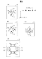
図2は、2軸磁気センサー回路130の内部に含まれる複数のホール素子の配列例と、それらの感磁方向を示す説明図である。ここでは、2軸磁気センサー回路130の表面に平行な方向として、互いに直交するX軸方向と、Y軸方向とを描いている。Z軸方向は、X軸方向及びY軸方向に直交しており、図1(A),1(B)の回転軸Cと平行な方向である。また、ホール素子の感磁方向(磁力線の検出方向)として、S極からN極に向かう方向を矢印で示している。内部に黒丸を含む白丸は、紙面の裏側から表側に向かう方向が感磁方向であることを示す。また、内部に「X」を含む白丸は、紙面の表側から裏側に向かう方向が感磁方向であることを示す。
FIG. 2 is an explanatory diagram showing an example of the arrangement of a plurality of Hall elements included in the biaxial
図2(A)の2軸磁気センサー回路130は、X軸方向を感磁方向とする2つのX軸ホール素子X1,X2と、Y軸方向を感磁方向とする2つのY軸ホール素子Y1,Y2とを有している。なお、X軸ホール素子の個数は、複数とすることが好ましく、2個に限らず3個以上でも良い。これはY軸ホール素子も同様である。後述するように、複数のX軸ホール素子X1,X2から第1磁気角信号sinθmが生成され、複数のY軸ホール素子Y1,Y2から第2磁気角信号cosθmが生成される。この点はさらに後述する。
The two-axis
図2(B)の2軸磁気センサー回路130は、第1組のホール素子YX1,YX2と、第2組のホール素子XY1,XY2とを有している。これらの2組のホール素子は、X軸方向とY軸方向に対して45度傾いた方向を感磁方向としている。図2(C)の2軸磁気センサー回路130は、2つのY軸ホール素子Y1,Y2と、2つのX軸ホール素子X1,X2とを有している。図2(C)の回路は、2つのY軸ホール素子Y1,Y2と2つのX軸ホール素子X1,X2の感磁方向が互いに向き合っている点で、図2(A)の回路と異なっている。図2(D)の2軸磁気センサー回路130は、4つのY軸ホール素子Y1a,Y1b,Y2a,Y2bと、4つのZ軸ホール素子Z1a,Z1b,Z2a,Z2bとを有している。図2(D)の2軸磁気センサー回路130を用いる場合には、上方の2つのY軸ホール素子Y1a,Y1bの出力を加算し、下方の2つのY軸ホール素子Y2a,Y2bを加算すれば、図2(A)の2つのY軸ホール素子Y1,Y2の出力と等価な出力を得ることが可能である。Z軸ホール素子Z1a,Z1b,Z2a,Z2bについても同様である。図2(B)〜(D)の2軸磁気センサー回路130のいずれを使用しても、その複数のホール素子の出力を合成することによって、磁気角信号sinθm,cosθmを生成することが可能である。なお、これらの例から理解できるように、2軸磁気センサー回路130は、直交する2つの方向に沿った磁場を検出することが可能な回路である。また、2軸磁気センサー回路130において、複数個のX軸センサー素子が、X軸に沿って互いに離れた部位に配置された第1組のX軸ホール素子と第2組のX軸ホール素子とを含み、同様に、複数個のY軸センサー素子が、Y軸に沿って互いに離れた部位に配置された第1組のY軸ホール素子と第2組のY軸ホール素子とを含むように構成することが可能である。
The biaxial
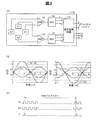
図3は、2軸磁気センサー回路130の回路構成と動作を示す説明図である。ここでは、図2(A)に示したホール素子の構成を使用している。2軸磁気センサー回路130は、X軸ホール素子X1,X2及びY軸ホール素子Y1,Y2の他に、増幅回路131,132と、AD変換回路133,134と、信号処理回路135とを有している。第1の増幅回路131には2つのX軸ホール素子X1,X2の出力が入力され、第2の増幅回路132には2つのY軸ホール素子Y1,Y2の出力が入力されている。図3(B)に示すように、2つのX軸ホール素子X1,X2の出力は、それぞれ第1の正弦波状の信号である。また、2つのY軸ホール素子Y1,Y2の出力は、第1の正弦波から90度位相がずれた第2の正弦波状(余弦波状)の信号である。第1の増幅回路131は、2つのX軸ホール素子X1,X2の出力の差分(X1−X2)を取る差動増幅器として構成されている。この理由は、第1の増幅回路131に入力される2つのX軸ホール素子X1,X2の出力の正負の符号が逆となるように、ホール素子X1,X2の回路や配線が構成されているからである。図3(B)の例では、2つのX軸ホール素子X1,X2の出力は、符号が逆で絶対値が等しい信号として描かれている。但し、2軸磁気センサー回路130の設置位置や磁石の磁束歪みによる磁極位置によっては、これらの2つのX軸ホール素子X1,X2の出力の絶対値が互いに異なる場合もある。しかし、この場合にも、第1の増幅回路131で2つのX軸ホール素子X1,X2の出力の差分(X1−X2)を取ることによって、2軸磁気センサー回路130の設置位置や磁石の磁束歪みによる磁極位置のずれに関わらず、磁気角θmに応じた正しい正弦波出力を得ることが可能である。これらの点は、Y軸ホール素子Y1,Y2及び第2の増幅回路132に関しても同様である。このように、複数のX軸ホール素子の出力信号の差を取ることによって正弦波信号(X1−X2)を生成し、複数のY軸ホール素子の出力信号の差を取ることによって正弦波信号(X1−X2)とは位相が90度異なる余弦波信号(Y1−Y2)を生成することができる。また、正弦波信号(X1−X2)と余弦波信号(Y1−Y2)に基づいて、回転体の位置(回転位置)を示す磁気角出力D1を生成することができる。
FIG. 3 is an explanatory diagram showing the circuit configuration and operation of the biaxial
なお、第1の増幅回路131に入力される2つのX軸ホール素子X1,X2の出力は、正負符号が同一の信号としてもよい。この場合には、第1の増幅回路131は、加算増幅器として構成される。但し、第1の増幅回路131を差動増幅器として構成すれば、2つの出力信号X1,X2に共通のノイズ(例えば、電磁コイルのPWM制御に伴う高周波ノイズ)が含まれている場合にも、それらの差分(X−X2)を取ることによってノイズを軽減できる点で好ましい。これらの点は、第2の増幅回路132も同様である。
Note that the outputs of the two X-axis Hall elements X1 and X2 input to the
これらの増幅回路131,132の出力(X1−X2),(Y1−Y2)は、AD変換回路133,134でそれぞれデジタル信号に変換されて、磁気角信号sinθm,cosθmとなる。信号処理回路135は、これらの磁気角信号sinθm,cosθmに基づいたデコード演算を行うことによって、図1(C)に示した磁気角出力D1を生成する。信号処理回路135は、更に、磁気角出力D1を利用して、図3(C)に示す2相パルス信号Pa,Pbと、周期信号Zとを生成する。
The outputs (X1-X2) and (Y1-Y2) of the
2相パルス信号Pa,Pbと、周期信号Zは、例えば以下のように生成される。磁気角出力D1は、磁気角θmを複数のビットで表した信号である。例えば、磁気角出力D1が12ビット信号として構成されている場合には、磁気角θmが0から2πまで変化する間に、磁気角出力D1の値は0から4095(=212−1)まで直線的に変化する。2相パルス信号Pa,Pbは、位相が互いに90度ずれた信号であり、光学式のインクリメンタルエンコーダーのA相出力及びB相出力に相当する信号である。周期信号Zは、磁気角θmが2π変化するたびに1パルス発生する信号であり、光学式のインクリメンタルエンコーダーのZ相信号に相当する信号である。例えば、A相パルス信号Paは、磁気角出力D1の最下位から2番目のビットの変化を示す信号として生成される。また、B相パルス信号Pbは、角度信号D1の最下位の2ビットの排他的論理和(XOR)を取った信号として生成される。周期信号Zは、角度信号D1の全ビットの否定論理和(NOR)を取った信号として生成される。角度信号D1が12ビットの信号の場合には、2相パルス信号Pa,Pbのパルスは、磁気角θmが2π変化する間に1024個発生する。 The two-phase pulse signals Pa and Pb and the periodic signal Z are generated as follows, for example. The magnetic angle output D1 is a signal representing the magnetic angle θm by a plurality of bits. For example, when the magnetic angle output D1 is configured as a 12-bit signal, the value of the magnetic angle output D1 is 0 to 4095 (= 2 12 −1) while the magnetic angle θm changes from 0 to 2π. It changes linearly. The two-phase pulse signals Pa and Pb are signals whose phases are shifted from each other by 90 degrees, and are signals corresponding to an A-phase output and a B-phase output of an optical incremental encoder. The periodic signal Z is a signal that generates one pulse every time the magnetic angle θm changes by 2π, and is a signal that corresponds to the Z-phase signal of the optical incremental encoder. For example, the A-phase pulse signal Pa is generated as a signal indicating a change in the second least significant bit of the magnetic angle output D1. The B-phase pulse signal Pb is generated as a signal obtained by taking an exclusive OR (XOR) of the least significant 2 bits of the angle signal D1. The periodic signal Z is generated as a signal obtained by taking a negative logical sum (NOR) of all bits of the angle signal D1. When the angle signal D1 is a 12-bit signal, 1024 pulses of the two-phase pulse signals Pa and Pb are generated while the magnetic angle θm changes by 2π.
信号処理回路135は、角度信号D1と、正弦波信号sinθmと、余弦波信号cosθmと、2相パルス信号Pa,Pbと、周期信号Zとを外部に出力することが可能である。ロータリーエンコーダー100Aを使用する装置は、これらの信号のうちのいくつかを用いて位置制御や速度制御を実行することが可能である。
The
このように、第1実施形態のロータリーエンコーダー100Aは、磁石体110の移動方向(周方向)と交差する方向に着磁されており、また、2軸磁気センサー回路130は、磁石体110の移動方向と磁石体110の着磁方向との両方向に平行な磁石体の表面から一定のギャップを介して配置されているので、2軸磁気センサー回路130の複数のホール素子の出力として、磁気歪みの少ない正弦波状の出力を得ることができる。従って、その磁気歪みの少ない正弦波状出力から、解像度の高い磁気角出力を得ることが可能である。また、2軸磁気センサー回路130は、複数のX軸ホール素子X1,X2と複数のY軸ホール素子Y1,Y2とを有しており、それらのホール素子の出力信号に応じて磁気角出力D1を生成するので、磁石体110に対して2軸磁気センサー回路130の設置位置が多少ずれた場合にも、正確な磁気角出力D1を得ることが可能である。
As described above, the
なお、磁石体110の極数Mは、第1実施形態では8であるが、極数Mは4以上の偶数とすることが好ましい。この理由は、極数Mが奇数の場合には機械角θrの2πの範囲が磁気角θmの2πの整数倍にならないので、角度検出が不便だからである。また、極数Mが2では、磁気角出力D1の解像度を十分に大きくできない可能性があるからである。
In addition, although the pole number M of the
B.第2実施形態(2つの磁石体を用いたロータリーエンコーダー、その1)
図4は、第2実施形態としてのロータリーエンコーダー100Bの構成と動作を示す説明図である。第2実施形態のロータリーエンコーダー100Bは、図1に示した第1実施形態のロータリーエンコーダー100Aに、第2の磁石体210と、第2のヨーク部材220と、第2の2軸磁気センサー回路230とを追加した構成を有している。第2の2軸磁気センサー回路230の構成及び動作は、第1実施形態で説明した2軸磁気センサー回路130の構成及び動作と同じである。
B. Second Embodiment (Rotary Encoder Using Two Magnets, Part 1)
FIG. 4 is an explanatory diagram showing the configuration and operation of the
第2の磁石体210は、第1の磁石体110の内側に配置されており、第1の磁石体110と同心円状の2極の環状磁石である。第2の磁石体210の着磁方法としては、ラジアル着磁よりも、平行着磁とすることが好ましい。この理由は、第1実施形態において説明した理由(第1の磁石体110の個々の小磁石110sの着磁方法として平行着磁が好ましい理由)と同じである。第2の磁石体210の平行着磁の着磁方向は、回転体の回転軸Cを通る方向(すなわち、磁石体210の径方向)に平行な方向とすることが好ましい。
The
第2の磁石体210の内周には、環状の第2のヨーク部材220が配置されている。但し、ヨーク部材120は、省略してもよい。なお、第1の磁石体110と第2の磁石体210の中間には、なんらかの磁性体製のヨーク部材を設けることが好ましい。この理由は、2つの磁石体110,210が、それぞれの2軸磁気センサー回路130,230に磁場干渉を起こさないようにするためである。
An annular
第2の2軸磁気センサー230は、第2の磁石体210の表面に対向した位置に一定のギャップを介して配置されている。換言すれば、第2の2軸磁気センサー回路230は、第2の磁石体210の移動方向(すなわち周方向)と、第2の磁石体210の着磁方向との両方向に平行な第2の磁石体210の表面から、一定のギャップを介して配置されている。また、第2の2軸磁気センサー回路230の設置位置は、第2の磁石体210の径方向に沿って測った第2の磁石体210の幅の中央よりも、第2の磁石体210と第2のヨーク部材220とを合わせた幅の中央に近い位置に配置することが好ましい。この点は、第1実施形態において説明した第1の2軸磁気センサー回路130の好ましい設置位置と同じである。
The second biaxial
図4(C)は、第2実施形態のロータリーエンコーダー100Bにおいて利用される小周期区間の区分の例を示している。ここでは、ロータリーエンコーダー100Bの回転体(第1の磁石体110と第2の磁石体210)の基準位置PPが12時の方向にある向きを基準として、90度毎に区分された4つの小周期区間が示されている。1つの小周期区間は、第1の磁石体110の磁気角θmが360度(2π)変化する区間(すなわち、2つの小磁石の区間)に相当する。小周期区間値Pxは、これらの4つの小周期区間を区別するための値であり、0〜3までの4つの値を取る。後述するように、この小周期区間値Pxは、第2の2軸磁気センサー回路230の磁気角出力から生成される。
FIG. 4C shows an example of a segment of a short cycle section used in the
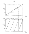
図7は、第1の2軸磁気センサー回路130から出力される第1磁気角出力D1と、第2の2軸磁気センサー回路230から出力される第2磁気角出力D2と、の例を示す説明図である。図7の横軸は機械角θrであり、縦軸は2つの2軸磁気センサー回路130,230の磁気角出力D1,D2である。本実施形態では、2軸磁気センサー回路130,230の磁気角出力D1,D2は、いずれも12ビットで構成されている。但し、一般には、第1の2軸磁気センサー回路130の第1磁気角出力D1をN1ビット(N1は2以上の整数)のデジタル信号とし、第2の2軸磁気センサー回路230の第2磁気角出力D2をN2ビット(N2は2以上の整数)のデジタル信号とすることができる。ここで、ビット数N1,N2は、同じ値としても良く、異なる値としても良い。
FIG. 7 shows an example of the first magnetic angle output D1 output from the first two-axis
図7(B)に示す第1磁気角出力D1は、第1の磁石体110(図4)の回転に伴う磁気角の変化を示しており、機械角θrが360度変化する間に、0から4095までの値が4回繰り返し発生する鋸刃状の変化を示す。すなわち、第1磁気角出力D1は、個々の小周期期間の間に、0から4095まで増加する直線的な変化を示す。一方、図7(A)に示す第2磁気角出力D2は、第2の磁石体210の回転に伴う磁気角の変化を示しており、機械角θrが360度変化する間に0から4095までの値が1回だけ発生する直線的な変化を示す。第2磁気角出力D2の最上位2ビットは、図4(C)で説明した小周期区間値Pxとして使用可能である。
The first magnetic angle output D1 shown in FIG. 7B indicates a change in the magnetic angle accompanying the rotation of the first magnet body 110 (FIG. 4), and is 0 while the mechanical angle θr changes 360 degrees. A value from 1 to 4095 indicates a sawtooth-like change that occurs repeatedly 4 times. That is, the first magnetic angle output D1 shows a linear change that increases from 0 to 4095 during each small period. On the other hand, the second magnetic angle output D2 shown in FIG. 7A shows the change of the magnetic angle accompanying the rotation of the
小周期区間値Pxは、機械角θrの絶対位置を高精度に決定するために使用される。機械角θrは、第2磁気角出力D2のみから12ビットの精度で検出可能である。しかし、小周期区間値Pxと第1磁気角出力D1との両方を使用すれば、更に高精度(高分解能)に機械角θrの絶対位置を決定することができる。具体的には、図7の例において、小周期区間値Pxが2ビットであり、第1磁気角出力D1が12ビットなので、これらの両方を使用して14ビットの精度(分解能)で機械角θrを検出可能である。 The short period interval value Px is used to determine the absolute position of the mechanical angle θr with high accuracy. The mechanical angle θr can be detected with an accuracy of 12 bits only from the second magnetic angle output D2. However, if both the short period interval value Px and the first magnetic angle output D1 are used, the absolute position of the mechanical angle θr can be determined with higher accuracy (high resolution). Specifically, in the example of FIG. 7, since the short cycle interval value Px is 2 bits and the first magnetic angle output D1 is 12 bits, both of them are used to obtain a mechanical angle with a precision (resolution) of 14 bits. θr can be detected.
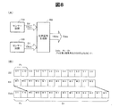
図8は、2つの2軸磁気センサー回路130,230の出力を用いて回転体の絶対位置(絶対角度)を決定する位置信号生成部300を示す説明図である。位置信号生成部300は、2つの2軸磁気センサー回路130,230の磁気角出力D1,D2を合成して、絶対位置出力Dabsを生成する。図8(B)は、位置信号生成部300の処理内容を示している。この例では、第1磁気角出力D1は、最下位ビットM0から最上位ビットM11までの12ビットの信号であり、第2磁気角出力D2も、最下位ビットS0から最上位ビットS11までの12ビットの信号である。第2磁気角出力D2の最上位2ビットS11,S10は、小周期区間値Pxとして使用される。絶対位置出力Dabsは、その最上位2ビットが小周期区間値Pxであり、下位12ビットが第1磁気角出力D1である。この絶対位置出力Dabsは、14ビットの精度で機械角θrの値を表す信号である。
FIG. 8 is an explanatory diagram showing a
なお、本実施形態において、2軸磁気センサー回路130,230のそれぞれは、複数のホール素子(図2の例参照)を用いている。従って、2軸磁気センサー回路130,230の電源がオンとなったときに、その時点における回転体の絶対位置(機械角θr)に応じて、図7に示した磁気角出力D1,D2を得ることができ、これらの磁気角出力D1,D2に応じて回転体の絶対位置(機械角θr)を決定することが可能である。従って、2軸磁気センサー回路130,230の電源オフ時に、その時点における回転体の絶対位置(機械角θrの値)を記憶しておく必要が無く、電源オン時に得られる2つの磁気角出力D1,D2のみから、電源オフ時の回転体の絶対位置を知ることができるという利点がある。
In the present embodiment, each of the biaxial
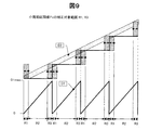
ところで、図7の例では、第1磁気角出力D1の小周期区間の境界と、第2磁気角出力D2から得られる小周期区間値Pxの値の変化位置とが一致している。しかしなら、実際の回路では、何らかの誤差によって両者が食い違う不具合が発生する可能性がある。このような不具合を防止するために、位置信号生成部300は、機械角θrの増大に応じて第1磁気角出力D1が最大値D1maxから最小値0に戻るタイミングと、小周期区間値Px(すなわち第2磁気角出力D2の最上位2ビット)がインクリメントするタイミングとが一致するように、小周期区間値Pxの補正を行うことが好ましい。
By the way, in the example of FIG. 7, the boundary of the short period section of the first magnetic angle output D1 and the change position of the value of the short period section value Px obtained from the second magnetic angle output D2 coincide. However, in an actual circuit, there is a possibility that a problem in which the two differ due to some error. In order to prevent such inconvenience, the position
図9は、位置信号生成部300によって行われる小周期区間値Pxの補正対象範囲を示す説明図である。図の下方には、第1磁気角出力D1の鋸刃状の変化が示されており、上方には第2磁気角出力D2の誤差の幅(上下方向の幅)がハッチングで示されている。第1磁気角出力D1は、その最小値0から最大値D1maxの範囲で変化しており、最大値D1maxに到達したあとに、最小値0に戻る。第1磁気角出力D1が最大値D1maxから最小値0に戻るタイミングと、第2磁気角出力D2の最上位2ビットがインクリメントするタイミングとが一致していれば、図8(B)で示したように、第2磁気角出力D2の最上位2ビットを小周期区間値Pxとしてそのまま使用できる。一方、両者のタイミングがずれている場合には、小周期区間値Pxの補正を行う。小周期区間値Pxの補正が必要となるのは、第1磁気角出力D1が最大値D1maxから最小値0に戻るタイミングの直後の範囲R1と、そのタイミングの直前の範囲R3である。これらの2つの範囲R1,R3の中間の範囲R2では、第2磁気角出力D2の最上位2ビットの値が、小周期区間値Pxとして正しい値を示すので、補正の必要は無い。
FIG. 9 is an explanatory diagram illustrating a correction target range of the short cycle interval value Px performed by the position
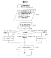
図10は、小周期区間値Pxの補正のアルゴリズムの一例を示すフローチャートである。この補正は、位置信号生成部300(図8)によって行われる。ステップS100では、第1磁気角出力D1のビット数N1と、第2磁気角出力D2のビット数N2と、小周期区間値Pxのビット数Nxと、が設定される。また、パラメータNss(=N2−Nx)、D1max(=2N1−1)も設定される。本実施形態では、N1=N2=12,Nx=2,Nss=10,D1max=4095である。 FIG. 10 is a flowchart illustrating an example of an algorithm for correcting the short cycle interval value Px. This correction is performed by the position signal generator 300 (FIG. 8). In step S100, the bit number N1 of the first magnetic angle output D1, the bit number N2 of the second magnetic angle output D2, and the bit number Nx of the short period interval value Px are set. Parameters Nss (= N2−Nx) and D1max (= 2 N1 −1) are also set. In this embodiment, N1 = N2 = 12, Nx = 2, Nss = 10, and D1max = 4095.
ステップS110では、位置信号生成部300が、2つの2軸磁気センサー回路130,230(図4)から磁気角出力D1,D2を受信する。ステップS120では、第1磁気角出力D1が、図9に示した3つの範囲R1,R2,R3のいずれにあるかが判定される。図10の例では、第1の範囲R1を0≦D1≦(D1max/4)とし、第2の範囲R2を(D1max/4)<D1<(D1max*3/4)とし、第3の範囲R3を(D1max*3/4)≦D1≦D1maxとしている。第1の範囲R1と第3の範囲R3では、小周期区間値Pxを補正するために、第2磁気角出力D2の補正を実行する。
In step S110, the
補正の実行工程であるステップS130〜S150は、以下の考えに基づいて実施される。
(1)第1磁気角出力D1が第1の範囲R1にある場合には、第2磁気角出力D2の上位2ビットで表される小周期区間値Pxが、誤って1つ小さな値になっている可能性がある。そこで、この可能性を排除するために、第2磁気角出力D2の下位Nssビットで表される最大値(=2Nss)の半分の値を第2磁気角出力D2に加算して、その上位Nxビットを小周期区間値Pxとして使用する(ステップS130,S150)。
(2)第1磁気角出力D1が第2の範囲R2にある場合には、第2磁気角出力D2の最上位2ビットをそのまま小周期区間値Pxとして使用する(ステップS150)。
(3)第1磁気角出力D1が第3の範囲R3にある場合には、第2磁気角出力D2の上位2ビットで表される小周期区間値Pxが、誤って1つ大きな値になっている可能性がある。そこで、この可能性を排除するため、第2磁気角出力D2の下位Nssビットで表される最大値(=2Nss)の半分の値を第2磁気角出力D2から減算して、その上位Nxビットを小周期区間値Pxとして使用する(ステップS140,S150)。
Steps S130 to S150, which are correction execution steps, are performed based on the following idea.
(1) When the first magnetic angle output D1 is in the first range R1, the short period interval value Px represented by the upper 2 bits of the second magnetic angle output D2 is erroneously reduced by one. There is a possibility. Therefore, in order to eliminate this possibility, a value half of the maximum value (= 2 Nss ) represented by the lower Nss bits of the second magnetic angle output D2 is added to the second magnetic angle output D2, and its upper Nx bits are used as the short cycle interval value Px (steps S130 and S150).
(2) When the first magnetic angle output D1 is in the second range R2, the most significant 2 bits of the second magnetic angle output D2 are used as they are as the short period interval value Px (step S150).
(3) When the first magnetic angle output D1 is in the third range R3, the short period interval value Px represented by the upper 2 bits of the second magnetic angle output D2 is erroneously increased by one. There is a possibility. Therefore, in order to eliminate this possibility, a value half of the maximum value (= 2 Nss ) represented by the lower Nss bits of the second magnetic angle output D2 is subtracted from the second magnetic angle output D2, and its upper Nx The bit is used as the short cycle interval value Px (steps S140 and S150).
このような補正を行うことによって、第1磁気角出力D1の小周期区間の境界と、小周期区間値Pxの変化時点とが常に一致するように、小周期区間値Pxを決定することが可能である。発明者の計算によれば、第2磁気角出力D2の磁気角誤差が±2N1-Nx-2以下であれば、上記の補正によって正しい小周期区間値Pxを得ることが可能である。例えば、N1=12,Nx=2の場合には、許容誤差は±28=±256である。この許容誤差はかなり大きいので、誤差に対する耐性が非常に大きく、実用上極めて有効な補正であることが理解できる。但し、磁気角出力D1,D2の誤差が無視できる程度のものであれば、小周期区間値Pxの補正は不要である。 By performing such correction, it is possible to determine the short cycle interval value Px so that the boundary of the short cycle interval of the first magnetic angle output D1 always coincides with the change point of the short cycle interval value Px. It is. According to the inventor's calculation, if the magnetic angle error of the second magnetic angle output D2 is ± 2 N1−Nx−2 or less, it is possible to obtain a correct small period interval value Px by the above correction. For example, if N1 = 12, Nx = 2, the tolerance is ± 2 8 = ± 256. Since this allowable error is quite large, it can be understood that the tolerance to the error is very large and that the correction is extremely effective in practice. However, if the error of the magnetic angle outputs D1 and D2 is negligible, the correction of the short period interval value Px is not necessary.
なお、補正を要する範囲R1,R3の最小幅は、磁気角出力D1,D2の誤差の大きさに応じて変わる。従って、これらの3つの範囲R1〜R3を、上述とは異なる所定の範囲にそれぞれ設定することが可能である。但し、3つの範囲R1〜R3のそれぞれは、幅がゼロでない範囲とすることが好ましい。また、小周期区間の境界の両側にある範囲R1,R3は、同じ幅とすることが好ましい。 Note that the minimum widths of the ranges R1 and R3 that require correction vary depending on the magnitude of the error in the magnetic angle outputs D1 and D2. Therefore, these three ranges R1 to R3 can be set to predetermined ranges different from those described above. However, each of the three ranges R1 to R3 is preferably set to a range in which the width is not zero. Moreover, it is preferable that the ranges R1 and R3 on both sides of the boundary of the short cycle section have the same width.
このように、第2実施形態では、位置信号生成部300は、第1の2軸磁気センサー回路130の第1磁気角出力D1と、第2の2軸磁気センサー回路230の第2磁気角出力D2とに応じて、回転体の絶対位置(機械角θr)を示す位置信号(絶対位置出力Dabs)を生成する。この位置信号Dabsを使用すれば、1つの2軸磁気センサー回路130(又は230)よりも高精度(高解像度)で位置を決定することが可能である。また、上述したように、本実施形態では、2軸磁気センサー回路130,230が複数のホール素子を用いているので、2軸磁気センサー回路130,230の電源オン時に得られる2つの磁気角出力D1,D2のみから、電源オフ時の回転体の絶対位置を直読で知ることができる。
As described above, in the second embodiment, the position
なお、第1の磁石体110の極数をM1とし、第2の磁石体210の極数をM2とした場合に、M1,M2をそれぞれ偶数とすることが好ましく、特に、M1を4以上の偶数とし、M2を2以上の偶数とすることが好ましい。こうすれば、1つの磁石体を用いる場合に比べて、より高精度に位置検出を行うことが可能である。
In addition, when the number of poles of the
また、第1の磁石体110の極数M1と、第2の磁石体210の極数M2は、M1/2とM2/2が互いに素である整数であることが好ましい。ここで、2つの整数が「互いに素」とは、両者が1以外の共通の約数を持たないことを意味する。M1/2とM2/2が互いに素となる整数であれば、第1の磁石体110の磁気角2πの区間(図7の小周期区間)の境界と、第2の磁石体210の磁気角2πの区間の境界とが一致する位置が、機械角θr=0の位置だけになるので、2つの磁気角出力D1,D2から機械角θrの絶対値を決定することができる。なお、第2実施形態では、M1=8,M2=2である。すなわち、第1の磁石体110の極数M1は、23に等しい。
The number of poles M1 of the
ところで、第2磁気角出力D2の最上位の数ビットを小周期区間値Pxとして利用するためには、第1の磁石体110の極数M1を2Q+1(Qは1以上の整数)に設定し、第2の磁石体210の極数M2を2に設定することが好ましい。このとき、位置信号生成部300は、第2磁気角出力D2の最上位Qビットを最上位に配置するとともに、その下に、第1磁気角出力D1の全ビット(N1ビット)を配置した(N1+Q)ビットの信号を、絶対位置出力Dabsとして生成することが好ましい。例えば、第2実施形態では、N1=12,Q=2なので、絶対位置出力Dabsは14ビットの信号となる。
By the way, in order to use the most significant bits of the second magnetic angle output D2 as the short period interval value Px, the number of poles M1 of the
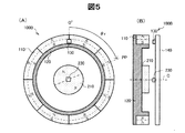
図5は、第2実施形態のロータリーエンコーダーの変形例を示す説明図である。図4のロータリーエンコーダーと異なる点は、第2の小磁石210を中実円盤状の形状とした点、第2の磁石体210用の第2のヨーク部材220を省略した点、及び、第2の2軸磁気センサー回路230を、第2の磁石体210の中心に向かい合う位置に配置した点、の3点だけである。図5のロータリーエンコーダーも、図4のロータリーエンコーダーとほとんど同じ性能を有する。
FIG. 5 is an explanatory diagram illustrating a modification of the rotary encoder according to the second embodiment. 4 differs from the rotary encoder of FIG. 4 in that the second
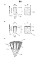
図6(A)〜(C)は、第1の磁石体110の他の構成例を示す説明図である。図6(A)は、第1の磁石体110用の小磁石110sを示す平面図及び側面図である。この小磁石110sは、等辺台形柱形状を有している。すなわち、平面視(図6(A)の左側)において等辺台形形状を有し、側面視(図6(A)の右側)において矩形形状を有している。平面視における等辺台形形状は、高さHと、底辺の幅WD1,WD2とを有する。また、側面視の矩形形状は、奥行きDP及び高さHを有する。この奥行きDPは、図1,図4,図5等に示す第1の磁石体110の厚み(紙面に垂直な方向の寸法)に相当する。台形の底辺の幅WD1,WD2は、第1の磁石体110の直径の寸法と、第1の磁石体110の極数M1とに応じて決められる。例えば、第1の磁石体110の直径を30mmとし、その極数を64とし、小磁石110sの高さHを5mmとした場合には、WD1=1.47mm,WD2=0.98mmとなり、小磁石110sのサイズが極めて小さなものとなる。このような微小サイズの台形形状の小磁石110sを製造しようとすると、その側面TPを形成するためのテーパー加工が困難である。
FIGS. 6A to 6C are explanatory diagrams illustrating other configuration examples of the
そこで、図6(B),(C)に示した例では、台形柱形状でなく、直方体形状を有する小磁石110sを用いて、図6(A)と実質的に等価な外形形状を有する小磁石体100d(以下、「分割磁石体110p」と呼ぶ)を構成している。すなわち、この分割磁石体110pは、直方体形状の小磁石110sと、被覆部材112とで構成されており、全体として等辺台形柱形状を有する。被覆部材112は、直方体形状の小磁石110sの周囲の少なくとも一部を被覆し、かつ、分割磁石体110pの全体の形状を等辺台形形状とするために設けられている部材である。被覆部材112の材料としては、加工のし易さ及び耐久性を考慮して、アルミ材や樹脂などの非磁性体材料を利用することが可能である。図6(C)は、多数の分割磁石体110pを並べることによって、多極の第1の磁石体110を構成した様子を示している。例えば、64個の分割磁石体110pを互いに接した状態で円環状に並べることによって、64極や32極の第1の小磁石体110を構成することが可能である。また、分割磁石体110pで構成された小磁石体110の内周側には、複数の分割磁石体110pを支持するための支持部材150を設けてもよい。この支持部材150としては、十分な剛性を有する材料で形成することが好ましく、例えば、SK5などの炭素工具鋼で形成することが好ましい。但し、支持部材150の代わりに、図1,図4,図5に示したヨーク部材120を用いて、複数の分割磁石体110pを支持するようにしてもよい。
Therefore, in the example shown in FIGS. 6B and 6C, a
このような分割磁石体110pを利用すれば、32極や64極等の極めて大きな極数の小磁石体110を容易に製造することができる。また、このような小磁石体110を用いて、位置精度の高いエンコーダーを容易に構成することが可能である。なお、図6(B)の例では、被覆部材112は直方体形状の小磁石110sの短辺の1つ(台形の底辺の幅WD2に相当する部分)を被覆していないが、被覆部材112が小磁石110sの全体を被覆するようにしてもよい。
By using such a divided
C.第3実施形態(2つの磁石体を用いたロータリーエンコーダー、その2)
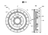
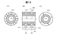
図11は、第3実施形態としてのロータリーエンコーダー100Cの構成と動作を示す説明図である。第3実施形態のロータリーエンコーダー100Cが第2実施形態のロータリーエンコーダー100B(図4)と異なる点は、2つの磁石体110,210の極数である。すなわち、第3実施形態のロータリーエンコーダー100Cの第1の磁石体110の極数M1は10であり、第2の磁石体210の極数M2は4である。第3実施形態の他の構成は、第2実施形態と同じである。
C. Third embodiment (rotary encoder using two magnet bodies, part 2)
FIG. 11 is an explanatory diagram showing the configuration and operation of a
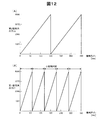
図12は、第3実施形態における磁気角出力D1,D2の例を示す説明図であり、第2実施形態の図7に相当する図である。第1の磁石体110の極数は10なので、第1磁気角出力D1は、機械角θrが0〜360度変化する間に、5つの小周期で変化する。一方、第2の磁石体210の極数は4なので、第2磁気角出力D2は、機械角θrが0〜360度変化する間に、2つの小周期で変化する。従って、位置信号生成部300(図8)は、これらの2つの磁気角出力D1,D2に基づいて、機械角θrを高精度に決定することが可能である。但し、第3実施形態では、第2磁気角出力D2の上位ビットをそのまま利用して絶対位置出力Dabsを得ることはできず、2つの磁気角出力D1,D2をデコードすることによって、絶対位置出力Dabsを生成する。このようなデコードを行うために、例えば、2つの磁気角出力D1,D2を入力とし、絶対位置出力Dabsを出力とするルックアップテーブルを使用することが可能である。或いは、算術的な演算によって、デコードを実施してもよい。なお、第3実施形態において、第1の磁石体110の極数M1(=10)と、第2の磁石体210の極数M2(=4)とは、M1/2(=5)とM2/2(=2)が互いに素となる整数である。
FIG. 12 is an explanatory diagram illustrating an example of the magnetic angle outputs D1 and D2 in the third embodiment, and corresponds to FIG. 7 in the second embodiment. Since the number of poles of the
この第3実施形態においても、第2実施形態と同様に、2つの磁石体110,210と2つの2軸磁気センサー回路130,230とを用いて、高精度に位置検出が可能である。但し、上述した第2実施形態では、第3実施形態で説明したデコードを行わずに済む点で、第3実施形態よりも好ましい。
In the third embodiment, as in the second embodiment, the position can be detected with high accuracy using the two
D.第4実施形態(2つの磁石体を用いたロータリーエンコーダー、その3)
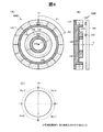
図13は、第4実施形態としてのロータリーエンコーダー100Dの構成を示す説明図である。このロータリーエンコーダー100Dは、中空円筒状のヨーク部材120の廻りに、同径の環状の第1の磁石体110dと第2の磁石体210dが、回転軸Cに平行な方向に沿って並列に配置された構成を有している。基板140には、2つの磁石体110d,210dの外周面に対して所定のギャップを介した位置に2軸磁気センサー回路130,230が設けられている。
D. Fourth Embodiment (Rotary Encoder Using Two Magnets, Part 3)
FIG. 13 is an explanatory diagram showing a configuration of a
第1の磁石体110dは8つの小磁石で構成されており、その極数M1は8である。第2の磁石体210dは2つの小磁石で構成されており、その極数M2は2である。但し、これらの極数M1,M2は、第2実施形態や第3実施形態で説明した種々の整数に設定することが可能である。
The
2つの磁石体110d、210dの個々の小磁石の着磁方向は、図13(B)の左右方向であり、図13(A),(C)では紙面に垂直な方向である。この着磁方向は、磁石体110d(210d)の回転方向(移動方向)に交差する方向に平行である。また、この着磁方向は、磁石体110d(210d)と基板140の対向方向と垂直な方向に平行で、かつ、磁石体110d(210d)の回転軸Cに平行な方向である。小磁石の着磁方法は、平行着磁とすることが好ましい。他の構成や動作は、第1〜第3実施形態で説明したものと同様である。
The magnetization directions of the individual small magnets of the two
第4実施形態のロータリーエンコーダー100Dも、第2実施形態や第3実施形態と同様の効果を有する。第2実施形態や第3実施形態のように同心円状の2つの磁石体110,210を使用するか、あるいは、第4実施形態のように同径の2つの磁石体110d、210dを使用するかは、エンコーダーの用途や空間的制約によって適宜選択可能である。例えば、より外径の小さな空間にエンコーダーを配置したい場合には、第4実施形態の方が第2実施形態や第3実施形態よりも有利である。
The
E.第5実施形態(2つの磁石体を用いたリニアエンコーダー)
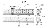
図14は、第5実施形態としてのリニアエンコーダー100Eの構成を示す説明図である。このリニアエンコーダー100Eは、直線的な棒状2つの磁石体110e,210eを有している。これらの磁石体110e,210eには、それぞれヨーク部材120,220が設けられている。なお、第1のヨーク部材120は、第1の磁石体110eの両側面(図14では、磁石体110eの上側の面と下側の面)の少なくとも一方に設けるようにしても良く、あるいは省略してもよい。第2のヨーク部材220も同様である。基板140には、2つの磁石体110e,210eの表面に対して所定のギャップを介した位置に2軸磁気センサー回路130,230が設けられている。
E. Fifth embodiment (linear encoder using two magnet bodies)
FIG. 14 is an explanatory diagram showing a configuration of a
第1の磁石体110eは8つの小磁石で構成されており、その極数M1は8である。第2の磁石体210eは2つの小磁石で構成されており、その極数M2は2である。但し、これらの極数M1,M2は、第2実施形態や第3実施形態で説明した種々の整数に設定することが可能である。小磁石の着磁方法は、平行着磁を利用することが好ましい。図14では、一例として、第1の磁石体110eの1つの小磁石のみに着磁方向が描かれている。この着磁方向は、磁石体110eの移動方向(図の左右方向)に交差する方向に平行である。また、この着磁方向は、磁石体110eと基板140の対向方向と垂直な方向に平行で、かつ、磁石体110eの移動方向に垂直な方向である。他の構成や動作は、第1〜第4実施形態で説明したものと同様である。
The
第5実施形態のリニアエンコーダー100Eも、第2〜第4実施形態と同様の効果を有する。なお、このリニアエンコーダー100Eの構成から、第2の磁石体210eと、それに関連する部材220,230とを省略してもよい。この場合には、第1実施形態で説明した1つの磁石体110を用いたロータリーエンコーダー100Aと同様な効果を奏するリニアエンコーダーを得ることができる。
The
F.第6実施形態(エンコーダーを備える電気機械装置)
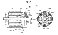
図15は、上述した実施形態のエンコーダーを備える電気機械装置を示す説明図である。電気機械装置としての電動モーター500は、コアレスの2相ブラシレスDCモーターとして構成されている。電動モーター500は、回転軸530の廻りに固定されたローター510と、ローター510の周囲に設けられたステーター520とを有する。
F. Sixth Embodiment (Electromechanical device including an encoder)
FIG. 15 is an explanatory diagram illustrating an electromechanical device including the encoder according to the above-described embodiment. The
図15(B)に示すように、ステーター520には、A相コイル522Aと、B相コイル522Bとがそれぞれ配置されている。これらのコイル522A,522Bは、図15(B)において、各コイルの中心を通る放射方向をそれぞれ中心として巻かれた集中巻きコイルである。
As shown in FIG. 15B, the
ローター510の外周面には、駆動力発生用の円筒状の磁石体110が設けられている。この磁石体110は8つの小磁石で構成されており、その極数M1は8である。この磁石体110は、ロータリーエンコーダー用の第1の磁石体としても機能する。ローター510の一方の端面には、ロータリーエンコーダー用の第2の磁石体210が設けられている。第1の磁石体110と第2の磁石体210の内周面には、ヨーク部材120,220がそれぞれ設けられている。第2の磁石体210が設けられている側のローター510の端面には、2つの磁石体110,210とそれらのヨーク部材120,220とを覆う磁力調整板512が設けられている。この磁力調整板512は、軟磁性体製であり、磁石体110、210の磁場を弱めることによって、磁気センサー回路の出力が飽和しないようにするためである。
A
2つの磁石体110,210の側面に対向する位置には、基板140が設けられている。基板140上には、第1の磁石体110の磁場を検出するための第1の2軸磁気センサー回路130と、第2の磁石体210の磁場を検出するための第2の2軸磁気センサー回路230と、制御部600とが設けられている。2軸磁気センサー回路130,230の構成及び動作は、図2及び図3で説明したものと同じである。図3で説明したように、1つの2軸磁気センサー回路130から、正弦波信号sinθmと余弦波信号cosθmの両方を出力することが可能である。従って、これらの2つの信号sinθm,cosθmを用いて、位相が90度異なる2相コイル用の駆動信号を生成することが可能である。但し、2相コイル用の駆動信号の生成に利用するために、2つの2軸磁気センサー回路130を、磁気角で90度位相がずれた位置に設けるようにしてもよい。但し、1つの2軸磁気センサー回路130から出力される正弦波信号sinθmと余弦波信号cosθmを用いて2相コイル用の駆動信号を生成するようにすれば、2つの磁気センサー回路を設ける場合に比べて、磁気センサー回路の実装位置のズレなどに起因する位相ズレが駆動信号に生じない点で好ましい。なお、2相コイル用の駆動信号の生成方法については後述する。
A
2つの磁石体110,210と2つの2軸磁気センサー回路130,230は、第2実施形態(図4〜図10)で説明したロータリーエンコーダー100Bと同様の構成、動作、及び効果を有するロータリーエンコーダーとして機能する。第1の磁石体110を構成する個々の小磁石は、ローター510の回転方向に交差する方向に着磁されている。その着磁方法は、平行着磁とすることが好ましい。これは、第2の磁石体210も同様である。
The two
図16は、電動モーター500の電気的構成を示すブロック図である。電動モーター500のモーター部として、ローター510と、2相分の電磁コイル522A,522Bと、2つの2軸磁気センサー回路130,230とが描かれている。制御部600は、主制御回路610と、2相分の駆動信号生成部620A,620Bと、2相分の駆動回路630A,630Bとを有している。主制御回路610には、第1の2軸磁気センサー回路130の出力信号D1,Pa,Pb,Z(図3参照)と、第2の2軸磁気センサー回路230の出力信号D2とが供給されており、これらの信号に基づいて、位置制御や速度制御を実行する。主制御回路610の内部構成については後述する。2相分の駆動信号生成部620A,620Bは、1つの2軸磁気センサー回路130から、正弦波と余弦波を示すデジタル信号sinθm,cosθmを受け取り、これらのデジタル信号sinθm,cosθmに基づくPWM制御を実行することによって2相分の駆動信号を生成する。これらの駆動信号は、駆動回路630A,630Bにそれぞれ供給される。駆動回路630A,630Bは、いわゆるブリッジドライバー回路である。正弦波状のデジタル信号sinθm,cosθmに基づくPWM制御によって2相分の駆動信号を生成する方法や、その回路構成については、例えば、本出願人により開示された特開2008−17678号公報の図10に示された回路(AD変換部を除く)を利用することが可能である。なお、本実施形態では、1つの2軸磁気センサー回路130から出力される正弦波信号sinθmと余弦波信号cosθmとを用いて2相分の駆動信号を生成するので、2つの磁気センサーを用いる場合に比べて、2つのセンサー位置相互のズレに起因する駆動信号の位相ズレが発生しない点で好ましい。この結果、モータの効率を高めることが可能である。
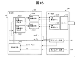
FIG. 16 is a block diagram showing an electrical configuration of the
図17は、主制御回路610の内部構成を示すブロック図である。主制御回路610の通信インターフェイス710は、第1の2軸磁気センサー回路130から第1磁気角出力D1を受信し、第2の2軸磁気センサー回路230から第2磁気角出力D2を受信する。これらの磁気角出力D1,D2は、図7に示したものと同じである。受信された磁気角出力D1,D2は、データ受信部720を介して位置信号生成部730に供給される。この位置信号生成部730は、図8〜図10で説明した位置信号生成部300と同じ機能を有する。位置信号生成部730で得られた絶対位置出力Dabsは、角速度算出部740に供給され、ローター510の角速度(回転速度)が算出される。また、この角速度は、角加速度算出部750に供給され、ローター510の角加速度が算出される。第1の2軸磁気センサー回路130の出力信号Pa,Pb,Z(図3)は、回転数算出部760に供給される。
FIG. 17 is a block diagram showing the internal configuration of the
図18は、回転数算出部760の内部構成と動作を示す説明図である。B相パルス信号Pbは、Dフリップフロップ761のデータ入力端子に供給され、A相パルス信号Paはクロック端子に供給される。Dフリップフロップ761の出力であるアップダウン信号Ua/Daは、アップダウンカウンター762の入力端子に供給される。アップダウン信号Ua/Daのハイレベルは、ローター510の回転方向が正方向(順方向)であることを示し、ローレベルは逆方向であることを示す。アップダウンカウンター762のクロック端子には、周期信号Zが供給されており、周期信号の立ち上がりエッジに応じてカウント値を変更する。すなわち、アップダウン信号Ua/Daがハイレベルの場合にはカウント値が1つインクリメントされ、アップダウン信号Ua/Daがローレベルの場合にはカウント値が1つデクリメントされる。アップダウンカウンター762のカウント値は、ラッチ763に供給される。ラッチ763のクロック端子には、周期信号Zが供給されており、周期信号Zの立ち下がりエッジに応じてカウント値Dnがラッチ763に保持される。ラッチ763の出力は、ローター510の回転数Nrとして外部に出力される。この回転数Nrは、電動モーター500によって駆動される部材(例えばロボットの関節)に関して、その所定の基準位置からの電動モーター500の回転数を示している。この回転数Nrは、回転数記憶部770(図17)に供給されて記憶される。
FIG. 18 is an explanatory diagram showing the internal configuration and operation of the rotation
図17の主制御回路610は、更に、入出力インターフェイス780と、レジスター790と、MPU795とを有している。入出力インターフェイス780は、上述した回路730,740,750,760,790,795に接続されており、必要に応じてこれらの回路からの出力を外部に供給する。レジスター790は、第1の磁石体110の極数や、ローター510の絶対位置(機械角θr)等のデータを一次的に格納している。回転数記憶部770やレジスター790は、制御部600の電源オフ時においてそれぞれの記憶内容を保持するために、電池800でバックアップされていることが好ましい。こうすれば、例えば、電動モーターがロボットの関節の駆動源として使用されている場合に、ロボットの電源オフ時の関節の位置を回転数記憶部770やレジスター790内の記憶内容に基づいて、次の電源オンの際に、関節の位置を正しく認識して制御を行うことが可能となる。MPU(Micro Processing Unit)795は、電動モーター500に関する各種の制御(例えばサーボ制御)を実行する。なお、MPU795が実行する制御処理は、図示しないメモリー内に格納されたコンピュータープログラムをMPU795が実行することによって実現される。
The
このように、上述した実施形態のエンコーダーを用いて電気機械装置を構成すれば、高精度に位置検出を行いつつ電気機械装置を制御することが可能である。特に、図15に示した電動モーター500では、電動モーター500の駆動力発生用の磁石体110を、エンコーダーの第1の磁石体としても利用しているので、少ない部材と単純な構造で高精度なエンコーダーを実現することができるという利点がある。
As described above, when the electromechanical device is configured using the encoder of the above-described embodiment, it is possible to control the electromechanical device while performing position detection with high accuracy. In particular, in the
なお、エンコーダーは、駆動力を発生する電気機械装置に限らず、発電を行う(すなわち、回生を行う)電気機械装置や、駆動と回生の両方を行うことが可能な電気機械装置に適用可能である。このような電気機械装置としては、例えば、2相ACブラシレスモーター、3相ACブラシレスモーター、3相同期モーターなどの各種のモーターや、ジェネレーター、モーター/ジェネレーターが存在する。これらの電気機械装置に用いるエンコーダーとしては、上述した第1〜第5実施形態で説明した各種のエンコーダーを使用可能である。これらの各種のエンコーダーを利用した電気機械装置においても、電気機械装置における駆動又は回生用の磁石体を、エンコーダーの第1の磁石体としても利用することが好ましい。但し、磁石体を共用せずに、電気機械装置の外部にエンコーダーを接続するようにしてもよい。 The encoder is applicable not only to an electromechanical device that generates a driving force but also to an electromechanical device that generates power (that is, performs regeneration) and an electromechanical device that can perform both driving and regeneration. is there. Examples of such electromechanical devices include various motors such as a two-phase AC brushless motor, a three-phase AC brushless motor, and a three-phase synchronous motor, a generator, and a motor / generator. As an encoder used for these electromechanical devices, various encoders described in the first to fifth embodiments can be used. Also in the electromechanical apparatus using these various encoders, it is preferable to use the driving or regenerating magnet body in the electromechanical apparatus as the first magnet body of the encoder. However, an encoder may be connected to the outside of the electromechanical device without sharing the magnet body.
G.エンコーダーを備える電気機械装置を利用した各種装置
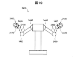
図19は、上記実施形態の電気機械装置を利用した双腕7軸ロボットの一例を示す説明図である。双腕7軸ロボット3450は、関節モーター3460と、把持部モーター3470と、アーム3480と、把持部3490と、を備える。関節モーター3460は、肩、肘、手首等の各関節部に相当する位置に配置されている。関節モーター3460は、アーム3480と把持部3490とを、3次元的に動作させるため、各関節につき2つのモーターを備えている。また、把持部モーター3470は、把持部3490を開閉し、把持部3490に物を掴ませる。双腕7軸ロボット3450において、関節モーター3460あるいは把持部モーター3470としては、上記実施形態で説明した電気機械装置を用いても良い。
G. Various devices Figure utilizing an electromechanical device comprising an encoder 19 is an explanatory diagram showing an example of a double-arm seven-axis robot using an electromechanical device of the above embodiment. The double-arm 7-
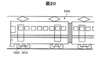
図20は、上記実施形態の電気機械装置を利用した鉄道車両を示す説明図である。この鉄道車両3500は、変速装置付モーター3510と、車輪3520とを有している。この変速装置付モーター3510は、車輪3520を駆動する。さらに、変速装置付モーター3510は、鉄道車両3500の制動時には発電機として利用され、電力が回生される。なお、変速装置付モーター3510としては、上記実施形態で説明した電気機械装置を用いても良い。
FIG. 20 is an explanatory diagram showing a railway vehicle using the electric machine device of the embodiment. The
図19及び図20の例から理解できるように、実施形態のエンコーダーを有する電気機械装置は、ロボットや、車両などの移動体を含む各種の装置に利用可能である。 As can be understood from the examples of FIGS. 19 and 20, the electromechanical device having the encoder of the embodiment can be used for various devices including a moving body such as a robot and a vehicle.
H.変形例:
上記実施形態において、ハードウェアによって実現されていた構成の一部をソフトウェアに置き換えるようにしてもよく、逆に、ソフトウェアによって実現されていた構成の一部をハードウェアに置き換えるようにしてもよい。
H. Variations:
In the above embodiment, a part of the configuration realized by hardware may be replaced by software, and conversely, a part of the configuration realized by software may be replaced by hardware.
本発明は、上述の実施形態や実施例、変形例に限られるものではなく、その趣旨を逸脱しない範囲において種々の構成で実現することができる。例えば、発明の概要の欄に記載した各形態中の技術的特徴に対応する実施形態、実施例、変形例中の技術的特徴は、上述の課題の一部又は全部を解決するために、あるいは、上述の効果の一部又は全部を達成するために、適宜、差し替えや、組み合わせを行うことが可能である。また、その技術的特徴が本明細書中に必須なものとして説明されていなければ、適宜、削除することが可能である。 The present invention is not limited to the above-described embodiments, examples, and modifications, and can be realized with various configurations without departing from the spirit thereof. For example, the technical features in the embodiments, examples, and modifications corresponding to the technical features in each embodiment described in the summary section of the invention are to solve some or all of the above-described problems, or In order to achieve part or all of the above effects, replacement or combination can be performed as appropriate. Further, if the technical feature is not described as essential in the present specification, it can be deleted as appropriate.
100A〜100D…ロータリーエンコーダー
100E…リニアエンコーダー
110,110d,110e…第1の磁石体
110p…分割磁石体
110s…小磁石
112…被覆部材
120…第1のヨーク部材
130…第1の2軸磁気センサー回路
131,132…増幅回路
135…信号処理回路
140…基板
150…支持部材
210,210d,210e…第2の磁石体
220…第2のヨーク部材
230…第2の2軸磁気センサー回路
300…位置信号生成部
500…電動モーター
510…ローター
512…磁力調整板
520…ステーター
522A,522B…電磁コイル
530…回転軸
600…制御部
610…主制御回路
620A,620B…駆動信号生成部
630A、630B…駆動回路
710…通信インターフェイス
720…データ受信部
730…位置信号生成部
740…角速度算出部
750…角加速度算出部
760…回転数算出部
762…アップダウンカウンター
763…ラッチ
770…回転数記憶部
780…入出力インターフェイス
790…レジスター
795…MPU
800…電池
3460…関節モーター
3470…把持部モーター
3480…アーム
3490…把持部
3500…鉄道車両
3510…変速装置付モーター
3520…車輪
DESCRIPTION OF
800 ...
Claims (13)
前記第2部材に設けられ、前記移動方向と交差する方向に着磁されたM1極(M1は4以上の偶数)の第1磁石体と、
前記第2部材に設けられ、前記移動方向と交差する方向に着磁されたM2極(M2は2以上の偶数)の第2磁石体と、
前記第1磁石体の表面から一定のギャップを有して、前記第1部材上に配置された第1の2軸磁気センサー回路と、
前記第2磁石体の表面から一定のギャップを有して、前記第1部材上に配置された第2の2軸磁気センサー回路と、
前記第1の2軸磁気センサー回路と前記第2の2軸磁気センサー回路の出力信号を処理する位置信号生成部と、
を備え、
前記位置信号生成部は、前記第1の2軸磁気センサー回路の第1磁気角出力と、前記第2の2軸磁気センサー回路の第2磁気角出力とに応じて、前記第1部材に対する前記第2部材の位置を示す位置信号を生成する、エンコーダー。 An encoder that measures the position of a second member that moves along a predetermined direction of movement with respect to the first member,
A first magnet body provided on the second member and magnetized in a direction crossing the moving direction (M1 is an even number of 4 or more);
A second magnet body provided on the second member and magnetized in a direction crossing the moving direction (M2 is an even number of 2 or more);
A first biaxial magnetic sensor circuit disposed on the first member with a certain gap from the surface of the first magnet body;
A second biaxial magnetic sensor circuit disposed on the first member with a certain gap from the surface of the second magnet body;
A position signal generator for processing output signals of the first two-axis magnetic sensor circuit and the second two-axis magnetic sensor circuit;
With
The position signal generator is configured to output the first member with respect to the first member according to a first magnetic angle output of the first two-axis magnetic sensor circuit and a second magnetic angle output of the second two-axis magnetic sensor circuit. An encoder that generates a position signal indicating the position of the second member.
前記第1の2軸磁気センサー回路と前記第2の2軸磁気センサー回路のそれぞれは、互いに直交するX軸とY軸のうちの前記X軸に沿った磁場を測定するための複数個のX軸センサー素子と、前記Y軸に沿った磁場を測定するための複数個のY軸センサ素子と、を含む、エンコーダー。 The encoder according to claim 1,
Each of the first two-axis magnetic sensor circuit and the second two-axis magnetic sensor circuit includes a plurality of Xs for measuring a magnetic field along the X axis of the X axis and the Y axis orthogonal to each other. An encoder comprising an axis sensor element and a plurality of Y axis sensor elements for measuring a magnetic field along the Y axis.
前記整数M1,M2は、M1/2とM2/2が互いに素となる整数であり、
前記位置信号生成部は、前記第1の2軸磁気センサーの第1磁気角出力と前記第2の2軸磁気センサーの第2磁気角出力から前記位置信号を生成する、エンコーダー。 The encoder according to claim 1 or 2,
The integers M1 and M2 are integers in which M1 / 2 and M2 / 2 are relatively prime,
The position signal generation unit is an encoder that generates the position signal from a first magnetic angle output of the first two-axis magnetic sensor and a second magnetic angle output of the second two-axis magnetic sensor.
前記整数M1は、2Q+1(Qは1以上の整数)に等しく、
前記整数M2は、2に等しく、
前記第1の2軸磁気センサー回路の第1磁気角出力は、前記第1部材に対する前記第2部材の相対位置を示すN1ビット(N1は2以上の整数)のデジタル信号であり、
前記第2の2軸磁気センサー回路の第2磁気角出力は、前記第1部材に対する前記第2部材の相対位置を示すN2ビット(N2は2以上の整数)のデジタル信号であり、
前記位置信号生成部は、前記第2磁気角出力の最上位Qビットを最上位に配置するとともに、前記第1磁気角出力のN1ビットを前記第2磁気角出力の前記最上位Qビットの下に配置した(N1+Q)ビットの信号を前記位置信号として生成する、エンコーダー。 The encoder according to claim 3, wherein
The integer M1 is equal to 2 Q + 1 (Q is an integer of 1 or more),
The integer M2 is equal to 2,
The first magnetic angle output of the first two-axis magnetic sensor circuit is a digital signal of N1 bits (N1 is an integer of 2 or more) indicating a relative position of the second member with respect to the first member.
The second magnetic angle output of the second two-axis magnetic sensor circuit is a digital signal of N2 bits (N2 is an integer of 2 or more) indicating the relative position of the second member with respect to the first member,
The position signal generation unit arranges the most significant Q bit of the second magnetic angle output at the most significant position, and sets the N1 bit of the first magnetic angle output below the most significant Q bit of the second magnetic angle output. An encoder that generates a signal of (N1 + Q) bits arranged in the position signal as the position signal.
前記位置信号生成部は、
前記第2の部材の移動に応じて前記第1の2軸磁気センサー回路の前記第1磁気角出力と前記第2の2軸磁気センサー回路の前記第2磁気角出力とがともに増加する際に、前記第1磁気角出力が前記第1磁気角出力の最大値から最小値に戻るタイミングと、前記第2磁気角出力の前記最上位Qビットがインクリメントするタイミングとが一致するように、前記第1磁気角出力に応じて前記第2磁気角出力の前記最上位Qビットを補正し、
前記補正後の前記第2磁気角出力の前記最上位Qビットを用いて、前記(N1+Q)ビットの前記位置信号を生成する、
エンコーダー。 The encoder according to claim 4, wherein
The position signal generator is
When the first magnetic angle output of the first two-axis magnetic sensor circuit and the second magnetic angle output of the second two-axis magnetic sensor circuit both increase in accordance with the movement of the second member. The timing at which the first magnetic angle output returns from the maximum value of the first magnetic angle output to the minimum value coincides with the timing at which the most significant Q bit of the second magnetic angle output is incremented. Correcting the most significant Q bit of the second magnetic angle output according to one magnetic angle output;
Generating the position signal of the (N1 + Q) bits using the most significant Q bits of the corrected second magnetic angle output;
encoder.
前記第2部材は、回転体であり、
前記第1磁石体を構成する個々の小磁石は、前記第1部材と前記第2部材の対向方向と垂直な着磁方向であって前記個々の小磁石の中心と前記回転体の回転軸とを結ぶ方向に平行な着磁方向に沿って平行着磁されている、エンコーダー。 The encoder according to any one of claims 1 to 5,
The second member is a rotating body,
The individual small magnets constituting the first magnet body are magnetized in a direction perpendicular to the opposing direction of the first member and the second member, the center of the individual small magnets, and the rotation axis of the rotating body. An encoder that is magnetized in parallel along the magnetizing direction parallel to the direction connecting the two.
前記第2部材は、前記第1磁石体の内周と外周の少なくとも一方に設けられた環状のヨーク部材を有し、
前記2軸磁気センサー回路は、前記第2部材の径方向に沿って測った磁束密度で0となる磁束中心部を外した位置に配置されている、エンコーダー。 The encoder according to claim 6, wherein
The second member has an annular yoke member provided on at least one of an inner periphery and an outer periphery of the first magnet body,
The two-axis magnetic sensor circuit is an encoder arranged at a position where a magnetic flux center portion where the magnetic flux density measured along the radial direction of the second member is zero is removed.
前記第1磁石体は、複数の分割磁石体を円環状に並べることによって構成されており、
各分割磁石体は、直方体形状を有する小磁石と、前記小磁石の周囲の少なくとも一部を被覆することによって前記分割磁石体の全体の形状を等辺台形柱形状とする被覆部材と、を有する、エンコーダー。 The encoder according to any one of claims 1 to 7,
The first magnet body is configured by arranging a plurality of divided magnet bodies in an annular shape,
Each divided magnet body includes a small magnet having a rectangular parallelepiped shape, and a covering member that covers at least a part of the periphery of the small magnet so that the entire shape of the divided magnet body is an isosceles trapezoidal columnar shape. encoder.
駆動又は回生用の磁石体と、
駆動又は回生用の電磁コイルと、
請求項1〜8のいずれか一項に記載のエンコーダーと、
前記電気機械装置の動作を制御する制御部と、
を備え、
前記駆動又は回生用の磁石体が、前記エンコーダーの前記第1磁石体として共用されている、
電気機械装置。 An electromechanical device,
A magnet for driving or regenerating,
An electromagnetic coil for driving or regeneration;
The encoder according to any one of claims 1 to 8,
A control unit for controlling the operation of the electromechanical device;
With
The driving or regenerating magnet body is shared as the first magnet body of the encoder,
Electromechanical equipment.
前記電気機械装置は、2相の電磁コイルを有する2相ACブラシレスモーターであり、
前記制御部は、前記エンコーダーの前記第1の2軸磁気センサー回路から出力される前記正弦波信号及び前記余弦波信号から、前記2相の電磁コイルの駆動信号を生成する駆動信号生成部を有する、電気機械装置。 An electromechanical device according to claim 9,
The electromechanical device is a two-phase AC brushless motor having a two-phase electromagnetic coil;
The control unit includes a drive signal generation unit that generates a drive signal for the two-phase electromagnetic coil from the sine wave signal and the cosine wave signal output from the first two-axis magnetic sensor circuit of the encoder. , Electromechanical devices.
磁石体と、
2相の電磁コイルと、
請求項1〜8のいずれか一項に記載のエンコーダーと、
前記電気機械装置の動作を制御する制御部と、
を備え、
前記制御部は、前記エンコーダーの前記第1の2軸磁気センサー回路から出力される前記正弦波信号及び前記余弦波信号から、前記2相の電磁コイルの駆動信号を生成する駆動信号生成部を有する、電気機械装置。 An electromechanical device operable as a two-phase AC brushless motor having a two-phase electromagnetic coil,
A magnet body;
A two-phase electromagnetic coil;
The encoder according to any one of claims 1 to 8,
A control unit for controlling the operation of the electromechanical device;
With
The control unit includes a drive signal generation unit that generates a drive signal for the two-phase electromagnetic coil from the sine wave signal and the cosine wave signal output from the first two-axis magnetic sensor circuit of the encoder. , Electromechanical devices.
駆動又は回生用の磁石体と、
駆動又は回生用の電磁コイルと、
請求項1〜8のいずれか一項に記載のエンコーダーと、
を備え、
前記駆動又は回生用の磁石体が、前記エンコーダーの前記磁石体として共用されている電気機械装置を有するロボット。 A robot,
A magnet for driving or regenerating,
An electromagnetic coil for driving or regeneration;
The encoder according to any one of claims 1 to 8,
With
A robot having an electromechanical device in which the magnet body for driving or regeneration is shared as the magnet body of the encoder.
駆動又は回生用の磁石体と、
駆動又は回生用の電磁コイルと、
請求項1〜8のいずれか一項に記載のエンコーダーと、
を備え、
前記駆動又は回生用の磁石体が、前記エンコーダーの前記磁石体として共用されてい
電気機械装置を有する鉄道車両。 A railway vehicle,
A magnet for driving or regenerating,
An electromagnetic coil for driving or regeneration;
The encoder according to any one of claims 1 to 8,
With
A railway vehicle having an electromechanical device in which the magnet body for driving or regeneration is shared as the magnet body of the encoder.
Priority Applications (1)
| Application Number | Priority Date | Filing Date | Title |
|---|---|---|---|
| JP2013256557A JP2015114209A (en) | 2013-12-12 | 2013-12-12 | Encoder and electromechanical device |
Applications Claiming Priority (1)
| Application Number | Priority Date | Filing Date | Title |
|---|---|---|---|
| JP2013256557A JP2015114209A (en) | 2013-12-12 | 2013-12-12 | Encoder and electromechanical device |
Publications (2)
| Publication Number | Publication Date |
|---|---|
| JP2015114209A true JP2015114209A (en) | 2015-06-22 |
| JP2015114209A5 JP2015114209A5 (en) | 2017-02-09 |
Family
ID=53528133
Family Applications (1)
| Application Number | Title | Priority Date | Filing Date |
|---|---|---|---|
| JP2013256557A Pending JP2015114209A (en) | 2013-12-12 | 2013-12-12 | Encoder and electromechanical device |
Country Status (1)
| Country | Link |
|---|---|
| JP (1) | JP2015114209A (en) |
Cited By (13)
| Publication number | Priority date | Publication date | Assignee | Title |
|---|---|---|---|---|
| CN106208539A (en) * | 2016-08-29 | 2016-12-07 | 华中科技大学 | A kind of magneto-electric encoder |
| KR20180027347A (en) * | 2016-09-06 | 2018-03-14 | 니혼 덴산 산쿄 가부시키가이샤 | Motor |
| CN110118552A (en) * | 2018-02-07 | 2019-08-13 | 日本电产三协株式会社 | Position detecting device and method for detecting position |
| CN110118551A (en) * | 2018-02-07 | 2019-08-13 | 日本电产三协株式会社 | Position detecting device and method for detecting position |
| CN110160560A (en) * | 2019-06-20 | 2019-08-23 | 上海岭先机器人科技股份有限公司 | The scaling method of magnetic coder, joint of robot and magnetic coder |
| JP2019525170A (en) * | 2016-07-22 | 2019-09-05 | シーエムアール サージカル リミテッドCmr Surgical Limited | Correction method of position reading value of position detection device |
| WO2019199056A1 (en) * | 2018-04-10 | 2019-10-17 | 엘지이노텍 주식회사 | Motor |
| JP2020088976A (en) * | 2018-11-20 | 2020-06-04 | 日本電産サンキョー株式会社 | motor |
| JP2020118593A (en) * | 2019-01-25 | 2020-08-06 | 日本電産サンキョー株式会社 | Manufacturing method of magnet assembly, magnet assembly and encoder |
| JP2020118594A (en) * | 2019-01-25 | 2020-08-06 | 日本電産サンキョー株式会社 | Magnet assembly and manufacturing method of magnet assembly, and encoder and motor with encoder |
| WO2021155263A1 (en) * | 2020-01-29 | 2021-08-05 | Cepheid | Motor having integrated actuator with absolute encoder and methods of use |
| CN117394609A (en) * | 2023-10-10 | 2024-01-12 | 山西省机电设计研究院有限公司 | Permanent magnet synchronous servo motor and electrical equipment |
| JP2024029235A (en) * | 2020-02-07 | 2024-03-05 | 株式会社プロテリアル | rotation detection device |
Citations (11)
| Publication number | Priority date | Publication date | Assignee | Title |
|---|---|---|---|---|
| JP2003121135A (en) * | 2001-10-10 | 2003-04-23 | Futaba Corp | Reader for linear scale |
| JP2004294145A (en) * | 2003-03-26 | 2004-10-21 | Ntn Corp | Bearing with rotation sensor |
| DE102004001570A1 (en) * | 2004-01-10 | 2005-12-29 | AMK Arnold Müller GmbH & Co. KG | Magnetic, linear or rotational, displacement measurement device has measurement bodies and matching sensors, with each body comprising series of opposing poles and one body having one more pole than the other |
| JP2006208049A (en) * | 2005-01-25 | 2006-08-10 | Denso Corp | Rotation angle detector |
| JP2007093569A (en) * | 2005-08-30 | 2007-04-12 | Hitachi Metals Ltd | Permanent magnet used for measurement of displacement, displacement amount sensor unit, and manufacturing method therefor |
| WO2008062778A1 (en) * | 2006-11-21 | 2008-05-29 | Hitachi Metals, Ltd. | Rotation angle detection device, rotation device, and rotation angle detection method |
| JP2009541739A (en) * | 2006-06-21 | 2009-11-26 | アレグロ・マイクロシステムズ・インコーポレーテッド | Method and apparatus for analog rotation sensor |
| WO2011057727A1 (en) * | 2009-11-13 | 2011-05-19 | Ab Skf | Position sensing method and unit |
| JP2011112417A (en) * | 2009-11-25 | 2011-06-09 | Seiko Epson Corp | Encoder and electromechanical device |
| JP2012112707A (en) * | 2010-11-22 | 2012-06-14 | Nidec Sankyo Corp | Rotary encoder |
| JP2013100016A (en) * | 2011-11-08 | 2013-05-23 | Jtekt Corp | Hydraulic power steering system |
-
2013
- 2013-12-12 JP JP2013256557A patent/JP2015114209A/en active Pending
Patent Citations (11)
| Publication number | Priority date | Publication date | Assignee | Title |
|---|---|---|---|---|
| JP2003121135A (en) * | 2001-10-10 | 2003-04-23 | Futaba Corp | Reader for linear scale |
| JP2004294145A (en) * | 2003-03-26 | 2004-10-21 | Ntn Corp | Bearing with rotation sensor |
| DE102004001570A1 (en) * | 2004-01-10 | 2005-12-29 | AMK Arnold Müller GmbH & Co. KG | Magnetic, linear or rotational, displacement measurement device has measurement bodies and matching sensors, with each body comprising series of opposing poles and one body having one more pole than the other |
| JP2006208049A (en) * | 2005-01-25 | 2006-08-10 | Denso Corp | Rotation angle detector |
| JP2007093569A (en) * | 2005-08-30 | 2007-04-12 | Hitachi Metals Ltd | Permanent magnet used for measurement of displacement, displacement amount sensor unit, and manufacturing method therefor |
| JP2009541739A (en) * | 2006-06-21 | 2009-11-26 | アレグロ・マイクロシステムズ・インコーポレーテッド | Method and apparatus for analog rotation sensor |
| WO2008062778A1 (en) * | 2006-11-21 | 2008-05-29 | Hitachi Metals, Ltd. | Rotation angle detection device, rotation device, and rotation angle detection method |
| WO2011057727A1 (en) * | 2009-11-13 | 2011-05-19 | Ab Skf | Position sensing method and unit |
| JP2011112417A (en) * | 2009-11-25 | 2011-06-09 | Seiko Epson Corp | Encoder and electromechanical device |
| JP2012112707A (en) * | 2010-11-22 | 2012-06-14 | Nidec Sankyo Corp | Rotary encoder |
| JP2013100016A (en) * | 2011-11-08 | 2013-05-23 | Jtekt Corp | Hydraulic power steering system |
Cited By (33)
| Publication number | Priority date | Publication date | Assignee | Title |
|---|---|---|---|---|
| JP7164513B2 (en) | 2016-07-22 | 2022-11-01 | シーエムアール サージカル リミテッド | Correction method of position reading value of position detection device |
| JP2023002689A (en) * | 2016-07-22 | 2023-01-10 | シーエムアール サージカル リミテッド | Correction method of position reading value of position detection device |
| US11619522B2 (en) | 2016-07-22 | 2023-04-04 | Cmr Surgical Limited | Calibrating position sensor readings |
| JP7374283B2 (en) | 2016-07-22 | 2023-11-06 | シーエムアール サージカル リミテッド | How to correct the position reading of a position sensing device |
| JP2019525170A (en) * | 2016-07-22 | 2019-09-05 | シーエムアール サージカル リミテッドCmr Surgical Limited | Correction method of position reading value of position detection device |
| CN106208539A (en) * | 2016-08-29 | 2016-12-07 | 华中科技大学 | A kind of magneto-electric encoder |
| CN106208539B (en) * | 2016-08-29 | 2018-10-16 | 华中科技大学 | A kind of magneto-electric encoder |
| KR20180027347A (en) * | 2016-09-06 | 2018-03-14 | 니혼 덴산 산쿄 가부시키가이샤 | Motor |
| JP2018042332A (en) * | 2016-09-06 | 2018-03-15 | 日本電産サンキョー株式会社 | motor |
| KR102436769B1 (en) | 2016-09-06 | 2022-08-26 | 니혼 덴산 산쿄 가부시키가이샤 | Motor |
| JP7085852B2 (en) | 2018-02-07 | 2022-06-17 | 日本電産サンキョー株式会社 | Position detection device and position detection method |
| JP2019138694A (en) * | 2018-02-07 | 2019-08-22 | 日本電産サンキョー株式会社 | Position detector and position detection method |
| JP2019138693A (en) * | 2018-02-07 | 2019-08-22 | 日本電産サンキョー株式会社 | Position detector and position detection method |
| CN110118551A (en) * | 2018-02-07 | 2019-08-13 | 日本电产三协株式会社 | Position detecting device and method for detecting position |
| JP7085851B2 (en) | 2018-02-07 | 2022-06-17 | 日本電産サンキョー株式会社 | Position detection device and position detection method |
| CN110118552A (en) * | 2018-02-07 | 2019-08-13 | 日本电产三协株式会社 | Position detecting device and method for detecting position |
| WO2019199056A1 (en) * | 2018-04-10 | 2019-10-17 | 엘지이노텍 주식회사 | Motor |
| US11411471B2 (en) | 2018-04-10 | 2022-08-09 | Lg Innotek Co., Ltd. | Motor |
| JP2020088976A (en) * | 2018-11-20 | 2020-06-04 | 日本電産サンキョー株式会社 | motor |
| JP7171380B2 (en) | 2018-11-20 | 2022-11-15 | 日本電産サンキョー株式会社 | motor |
| JP7270395B2 (en) | 2019-01-25 | 2023-05-10 | ニデックインスツルメンツ株式会社 | Method for manufacturing magnet assembly, encoder and motor with encoder |
| JP2020118594A (en) * | 2019-01-25 | 2020-08-06 | 日本電産サンキョー株式会社 | Magnet assembly and manufacturing method of magnet assembly, and encoder and motor with encoder |
| JP2020118593A (en) * | 2019-01-25 | 2020-08-06 | 日本電産サンキョー株式会社 | Manufacturing method of magnet assembly, magnet assembly and encoder |
| CN110160560A (en) * | 2019-06-20 | 2019-08-23 | 上海岭先机器人科技股份有限公司 | The scaling method of magnetic coder, joint of robot and magnetic coder |
| CN110160560B (en) * | 2019-06-20 | 2024-06-28 | 上海岭先机器人科技股份有限公司 | Magnetic encoder, robot joint and calibration method of magnetic encoder |
| CN115211006A (en) * | 2020-01-29 | 2022-10-18 | 塞弗德公司 | Motor with integrated actuator with absolute encoder and method of use |
| WO2021155263A1 (en) * | 2020-01-29 | 2021-08-05 | Cepheid | Motor having integrated actuator with absolute encoder and methods of use |
| US11876479B2 (en) | 2020-01-29 | 2024-01-16 | Cepheid | Motor having integrated actuator with absolute encoder and methods of use |
| JP2024029235A (en) * | 2020-02-07 | 2024-03-05 | 株式会社プロテリアル | rotation detection device |
| US12123750B2 (en) | 2020-02-07 | 2024-10-22 | Proterial, Ltd. | Rotation detection device |
| JP7609312B2 (en) | 2020-02-07 | 2025-01-07 | 株式会社プロテリアル | Rotation Detection Device |
| CN117394609A (en) * | 2023-10-10 | 2024-01-12 | 山西省机电设计研究院有限公司 | Permanent magnet synchronous servo motor and electrical equipment |
| CN117394609B (en) * | 2023-10-10 | 2024-06-04 | 山西省机电设计研究院有限公司 | Permanent magnet synchronous servo motor and electrical equipment |
Similar Documents
| Publication | Publication Date | Title |
|---|---|---|
| JP2015114209A (en) | Encoder and electromechanical device | |
| CN104931075A (en) | Encoders, electromechanical devices, robots and rail vehicles | |
| TWI650528B (en) | Rotation angle detecting device and rotation angle detecting method | |
| CN103443590B (en) | Absolute encoder device and motor | |
| JP2015175762A (en) | Encoder, electromechanical device, robot, and railway vehicle | |
| JP2015114209A5 (en) | ||
| JP2020153806A (en) | Rotation angle detector | |
| JP2012042352A (en) | Rotation angle and torque sensor | |
| JP4900838B2 (en) | Position detection device and linear drive device | |
| JP2014163873A (en) | Magnetic encoder, electromechanical device, mobile body, and robot | |
| JP2016082685A (en) | Brushless motor and electric power steering device | |
| JP5545121B2 (en) | Rotation angle / torque sensor | |
| JP5036669B2 (en) | Position detection device for moving parts, 2-DOF actuator | |
| JP5201493B2 (en) | Position detection device and linear drive device | |
| KR20250092251A (en) | Multi-rotation angle detection device | |
| JP2015114208A (en) | Encoder and electromechanical device | |
| JPWO2007055135A1 (en) | Magnetic encoder device | |
| JP2015061411A (en) | Linear/rotary actuator and method for controlling the same | |
| JP2015175760A (en) | Encoder, electromechanical device, robot, and railway vehicle | |
| JP7572471B2 (en) | Multi-rotation angle detection device and segment counter therefor | |
| JP2018048870A (en) | Rotation angle detector | |
| JP6525846B2 (en) | Resolver | |
| JP2018201299A (en) | Biaxial-integrated type motor | |
| JP3136921B2 (en) | Magnetic sensor and motor with magnetic sensor | |
| JP2015114208A5 (en) |
Legal Events
| Date | Code | Title | Description |
|---|---|---|---|
| A711 | Notification of change in applicant |
Free format text: JAPANESE INTERMEDIATE CODE: A711 Effective date: 20160907 |
|
| RD03 | Notification of appointment of power of attorney |
Free format text: JAPANESE INTERMEDIATE CODE: A7423 Effective date: 20161028 |
|
| RD04 | Notification of resignation of power of attorney |
Free format text: JAPANESE INTERMEDIATE CODE: A7424 Effective date: 20161031 |
|
| A521 | Request for written amendment filed |
Free format text: JAPANESE INTERMEDIATE CODE: A523 Effective date: 20161108 |
|
| A621 | Written request for application examination |
Free format text: JAPANESE INTERMEDIATE CODE: A621 Effective date: 20161108 |
|
| A977 | Report on retrieval |
Free format text: JAPANESE INTERMEDIATE CODE: A971007 Effective date: 20170807 |
|
| A131 | Notification of reasons for refusal |
Free format text: JAPANESE INTERMEDIATE CODE: A131 Effective date: 20170815 |
|
| A521 | Request for written amendment filed |
Free format text: JAPANESE INTERMEDIATE CODE: A523 Effective date: 20171016 |
|
| A02 | Decision of refusal |
Free format text: JAPANESE INTERMEDIATE CODE: A02 Effective date: 20171031 |