JP6334892B2 - POSITION DETECTION DEVICE AND LENS DEVICE AND PHOTOGRAPHING DEVICE HAVING THE SAME - Google Patents
POSITION DETECTION DEVICE AND LENS DEVICE AND PHOTOGRAPHING DEVICE HAVING THE SAME Download PDFInfo
- Publication number
- JP6334892B2 JP6334892B2 JP2013224847A JP2013224847A JP6334892B2 JP 6334892 B2 JP6334892 B2 JP 6334892B2 JP 2013224847 A JP2013224847 A JP 2013224847A JP 2013224847 A JP2013224847 A JP 2013224847A JP 6334892 B2 JP6334892 B2 JP 6334892B2
- Authority
- JP
- Japan
- Prior art keywords
- signal
- position value
- relative position
- absolute position
- absolute
- Prior art date
- Legal status (The legal status is an assumption and is not a legal conclusion. Google has not performed a legal analysis and makes no representation as to the accuracy of the status listed.)
- Active
Links
- 238000001514 detection method Methods 0.000 title claims description 23
- 238000006073 displacement reaction Methods 0.000 claims description 90
- 230000003287 optical effect Effects 0.000 claims description 7
- 238000003384 imaging method Methods 0.000 claims description 3
- 238000000034 method Methods 0.000 description 60
- 238000004364 calculation method Methods 0.000 description 39
- 238000006243 chemical reaction Methods 0.000 description 7
- 238000010586 diagram Methods 0.000 description 7
- 230000005856 abnormality Effects 0.000 description 6
- 239000011295 pitch Substances 0.000 description 6
- 239000000428 dust Substances 0.000 description 4
- 230000000737 periodic effect Effects 0.000 description 3
- 230000010363 phase shift Effects 0.000 description 3
- 230000000694 effects Effects 0.000 description 2
- 238000005259 measurement Methods 0.000 description 2
- 230000001360 synchronised effect Effects 0.000 description 2
- 230000002159 abnormal effect Effects 0.000 description 1
- 230000007547 defect Effects 0.000 description 1
- 238000004519 manufacturing process Methods 0.000 description 1
- 238000011084 recovery Methods 0.000 description 1
- 239000000126 substance Substances 0.000 description 1
Images


Classifications
-
- H—ELECTRICITY
- H04—ELECTRIC COMMUNICATION TECHNIQUE
- H04N—PICTORIAL COMMUNICATION, e.g. TELEVISION
- H04N23/00—Cameras or camera modules comprising electronic image sensors; Control thereof
- H04N23/60—Control of cameras or camera modules
-
- G—PHYSICS
- G01—MEASURING; TESTING
- G01D—MEASURING NOT SPECIALLY ADAPTED FOR A SPECIFIC VARIABLE; ARRANGEMENTS FOR MEASURING TWO OR MORE VARIABLES NOT COVERED IN A SINGLE OTHER SUBCLASS; TARIFF METERING APPARATUS; MEASURING OR TESTING NOT OTHERWISE PROVIDED FOR
- G01D5/00—Mechanical means for transferring the output of a sensing member; Means for converting the output of a sensing member to another variable where the form or nature of the sensing member does not constrain the means for converting; Transducers not specially adapted for a specific variable
- G01D5/12—Mechanical means for transferring the output of a sensing member; Means for converting the output of a sensing member to another variable where the form or nature of the sensing member does not constrain the means for converting; Transducers not specially adapted for a specific variable using electric or magnetic means
- G01D5/244—Mechanical means for transferring the output of a sensing member; Means for converting the output of a sensing member to another variable where the form or nature of the sensing member does not constrain the means for converting; Transducers not specially adapted for a specific variable using electric or magnetic means influencing characteristics of pulses or pulse trains; generating pulses or pulse trains
- G01D5/24457—Failure detection
- G01D5/24461—Failure detection by redundancy or plausibility
-
- G—PHYSICS
- G01—MEASURING; TESTING
- G01B—MEASURING LENGTH, THICKNESS OR SIMILAR LINEAR DIMENSIONS; MEASURING ANGLES; MEASURING AREAS; MEASURING IRREGULARITIES OF SURFACES OR CONTOURS
- G01B11/00—Measuring arrangements characterised by the use of optical techniques
- G01B11/14—Measuring arrangements characterised by the use of optical techniques for measuring distance or clearance between spaced objects or spaced apertures
-
- G—PHYSICS
- G01—MEASURING; TESTING
- G01D—MEASURING NOT SPECIALLY ADAPTED FOR A SPECIFIC VARIABLE; ARRANGEMENTS FOR MEASURING TWO OR MORE VARIABLES NOT COVERED IN A SINGLE OTHER SUBCLASS; TARIFF METERING APPARATUS; MEASURING OR TESTING NOT OTHERWISE PROVIDED FOR
- G01D5/00—Mechanical means for transferring the output of a sensing member; Means for converting the output of a sensing member to another variable where the form or nature of the sensing member does not constrain the means for converting; Transducers not specially adapted for a specific variable
- G01D5/26—Mechanical means for transferring the output of a sensing member; Means for converting the output of a sensing member to another variable where the form or nature of the sensing member does not constrain the means for converting; Transducers not specially adapted for a specific variable characterised by optical transfer means, i.e. using infrared, visible, or ultraviolet light
- G01D5/32—Mechanical means for transferring the output of a sensing member; Means for converting the output of a sensing member to another variable where the form or nature of the sensing member does not constrain the means for converting; Transducers not specially adapted for a specific variable characterised by optical transfer means, i.e. using infrared, visible, or ultraviolet light with attenuation or whole or partial obturation of beams of light
- G01D5/34—Mechanical means for transferring the output of a sensing member; Means for converting the output of a sensing member to another variable where the form or nature of the sensing member does not constrain the means for converting; Transducers not specially adapted for a specific variable characterised by optical transfer means, i.e. using infrared, visible, or ultraviolet light with attenuation or whole or partial obturation of beams of light the beams of light being detected by photocells
- G01D5/347—Mechanical means for transferring the output of a sensing member; Means for converting the output of a sensing member to another variable where the form or nature of the sensing member does not constrain the means for converting; Transducers not specially adapted for a specific variable characterised by optical transfer means, i.e. using infrared, visible, or ultraviolet light with attenuation or whole or partial obturation of beams of light the beams of light being detected by photocells using displacement encoding scales
- G01D5/34776—Absolute encoders with analogue or digital scales
- G01D5/34792—Absolute encoders with analogue or digital scales with only digital scales or both digital and incremental scales
- G01D5/34794—Optical encoders using the Vernier principle, i.e. incorporating two or more tracks having a (n, n+1, ...) relationship
Description
本発明は、可動要素の位置を検出する位置検出装置及びそれを有するレンズ装置及び撮影装置に関するものである。 The present invention relates to a position detection device that detects the position of a movable element, a lens device having the position detection device, and an imaging device.
従来、物体の移動距離を測定するための装置として、相対移動距離を測定するインクリメンタルエンコーダの他、絶対位置の測長を可能としたアブソリュートエンコーダが知られている。 Conventionally, as an apparatus for measuring the moving distance of an object, an absolute encoder capable of measuring an absolute position is known in addition to an incremental encoder that measures a relative moving distance.
特許文献1には、バーニア型アブソリュートエンコーダが開示されている。構成としては、トラック上にピッチの異なる2つ以上の格子パターンを設けている。これら各格子パターンのピッチ差に起因する検出信号の微妙なずれから、1回循環する区間内での位置の特定(以後、アブソリュート化又は絶対位置演算とも記載する)を行う。
また特許文献2には、バーニア型アブソリュートエンコーダにおいて、アブソリュート化のタイミングに関する特許が開示されている。構成としては、細かいピッチと粗いピッチでトラックパターンが形成されている。これら各トラックからアブソリュート化を行うタイミングとして、細かいピッチのインクリメンタル計測に誤検出が発生しない速度まで低下した時に、アブソリュート化を行う。
しかしながら、特許文献1に開示されたアブソリュートエンコーダには以下のような問題がある。スケール上にゴミやキズがある場合、誤った検出信号から絶対位置を演算することとなる。この結果、正しい絶対位置を演算することができない問題が発生する。
However, the absolute encoder disclosed in
また、特許文献2に開示されたアブソリュートエンコーダには以下のような問題がある。細かいピッチのインクリメンタル計測に誤検出が発生しない速度まで低下した位置において、スケール上にゴミやキズがある場合に、誤った検出信号を検出してしまう。この結果も同様に誤った検出信号から絶対位置を演算することとなる。
Further, the absolute encoder disclosed in
そこで、本発明は、例えば、信頼性の高い位置検出装置を提供する。 The present invention provides, for example, a high not position detecting device reliability.
上記目的を達成するために、本発明の位置検出装置は、第1要素および第2要素のうちの一方に備えられ、互いに異なる周期で形成された複数のパターン列を有するスケールと、前記第1要素および前記第2要素のうちの他方に備えられ、前記複数のパターン列に対応する複数の信号を取得するセンサと、前記複数の信号に基づいて、前記第1要素および前記第2要素のうちの一方に対する前記第1要素および前記第2要素のうちの他方の位置を得、前記複数の信号のうちの1つ以上の信号に基づいて、前記他方の位置に対する変位量を得る処理部と、を有し、前記処理部は、前記他方の位置として得られた第一位置と、前記第一位置とは異なる、前記他方の位置として得られた第二位置との差と、前記第一位置に対する前記第二位置での前記変位量とに基づく、前記第二位置を前記変位量の基準位置とするかの判断を行い、前記第二位置を前記基準位置としないと判断した場合には、前記第一位置および前記第二位置とは設定量以上離れた、前記他方の位置として得られた第三位置を前記基準位置とする、ことを特徴とする。 In order to achieve the above object, a position detection device of the present invention is provided with one of a first element and a second element, and has a scale having a plurality of pattern rows formed at different periods, and the first element. A sensor that is provided on the other of the element and the second element, and that acquires a plurality of signals corresponding to the plurality of pattern rows; and based on the plurality of signals, the first element and the second element give other position of said first element and said second element relative to one of, based on one or more signals of the plurality of signals, and a processing unit to obtain a displacement amount with respect to the other position, has, the processing unit includes a first position location obtained as the position of the other, the different from the first position location, and the difference between the second-largest location obtained as the position of the other, the Previous in the second position relative to the first position location Rather groups Dzu to the Displacement amount, said second position do judgment as a reference position of the displacement, when the second position is determined not to the reference position, the first position and A third position obtained as the other position that is more than a set amount away from the second position is defined as the reference position .
本発明によれば、例えば、信頼性の高い位置検出装置を提供することができる。 According to the present invention , for example, a highly reliable position detection device can be provided.
以下に、本発明の好ましい実施の形態を、添付の図面に基づいて詳細に説明する。 Hereinafter, preferred embodiments of the present invention will be described in detail with reference to the accompanying drawings.
以下、図1を用いて、本発明の位置検出装置の第1の実施例を説明する。
図1は、実施例1の構成ブロック図である。図1において、ABS/INC演算部102は、ABSセンサーから出力される信号を元に、固定要素の所定の基準位置に対する可動要素の位置をその位置で取得された信号に基づいて演算される位置(絶対位置)である絶対位置値Pabs、及び、固定要素に対する可動要素のある位置からの変位量(相対位置)である相対位置値Pincを演算する演算部である。読取パターン切替え部103は、2種類のパターン列により発生する2種類の信号出力をABSセンサー104から切替えて出力させる。ABSセンサー(位置信号取得手段)104は、固定要素に対しての可動要素の絶対位置を演算するための信号を出力する絶対位置センサーである。ABSセンサー104の内部構成及び出力信号については後述する。AD変換部105は、ABSセンサー104から出力されるアナログ信号をデジタル信号に変替するAD変換部である。ABS決定部101は、ABS/INC演算部102が演算した絶対位置値Pabs及び相対位置値Pincを元に現在の絶対位置Pabscを決定する絶対位置決定部である。ABS決定部101及びABS/INC演算部102は例えば一つのCPU内に構成される。
Hereinafter, a first embodiment of the position detection apparatus of the present invention will be described with reference to FIG.
FIG. 1 is a configuration block diagram of the first embodiment. In FIG. 1, an ABS /
次に本実施例の動作について説明する。
ABS決定部101は、ABS/INC演算部102に対して、絶対位置値Pabsの演算の要求を行う。ABS/INC演算部102は、ABS決定部101からの絶対位置演算要求を受けると、読取パターン切替え部103に、2種類のパターン列に対応する信号を順次ABSセンサー104から出力するように指令を出す。読取パターン切替え部103は、ABSセンサー104に順次、後述する2種類のパターンの信号を出力する指示を行う。ABSセンサー104は、読取パターン切替え部103の指示に従い、2種類のパターン列に対応する信号を順次出力する。ABSセンサーから出力される2種類のパターン列に対応する信号は、AD変換部105でデジタル信号に変換され、ABS/INC演算部102に出力される。ABS/INC演算部は、2種類のパターン列に対応する信号を元に絶対位置値Pabsを演算し、ABS決定部101に出力する。
Next, the operation of this embodiment will be described.
The
一方ABS/INC演算部102は、相対位置値Pincを演算するために必要なパターン列に対応する信号をABSセンサー104から出力させるように読取パターン切替え部103に指令を出す。ABS/INC演算部102は、相対位置値Pincを演算するために必要なパターン列に対応する信号に切り替えた後、前述と同様にAD変換部105から出力されたパターン列に対応する信号を元に相対位置値Pincを演算し、ABS決定部101に相対位置値Pincを定期的に出力する。絶対位置及び相対位置演算方法については後述する。ABS決定部101は、複数位置での絶対位置値Pabs及び相対位置値Pincを元に絶対位置を決定する。ABS決定部101が絶対位置を決定する方法については後述する。
On the other hand, the ABS /
次にABSセンサー104の内部構成及び出力信号について説明する。
図2はABSセンサー104の断面図である。図2において、可動要素21は、紙面に垂直方向となるX軸方向に移動可能な可動部である。固定要素22は、可動要素21の絶対位置の基準となる要素である。光源201は発光部であり、例えばLEDである。スケール部202は全長でスリット数の異なる等間隔の2つのパターン列203a,203bを有するスケール部である。受光部204a,204bはそれぞれ、パターン列203a,203bにより反射した光源201からの光を受光するための受光部であり、例えばフォトダイオードアレイで構成される。信号処理回路205は、受光部204a,204bで受光した信号を処理し、読取パターン切替え部103の切替え信号に応じて、パターン列203a,203bの何れかに対応する信号を出力する信号処理回路である。なお、本実施例においては、可動要素21にスケール部202を備え、固定要素22に光源201及び受光部204a、204bを備える構成を例示した。しかし、これに限定されることはなく、固定要素及び可動要素の内の一方にスケール部202を、他方に光源201及び受光部204a、204bを備える構成とすればよい。後述する実施例においても同様である。
Next, the internal configuration and output signal of the
FIG. 2 is a cross-sectional view of the
図3は、本実施形態におけるスケール部202の平面図である。図3では反射型のスリットパターン列(反射パターン列)を一例として示している。スケール部202は、第一パターン203aと第二パターン203bの2つのパターン列を備えて構成されている。パターン列203a,203bの反射部(黒塗り部)に光源201から出射した光が入射すると、受光部204a,204bに向けてそれぞれ反射するような構成となっている。第一パターン203aの反射部はP1間隔で等間隔に形成されている。また第二パターン203bの反射部はP2間隔で等間隔に形成されている。本実施例では、P1は、スケールの全長Lmaxに対して反射部が40個、つまり全長Lに対して40周期となるように構成されている。また、P2は、パターン列の全長Lmaxに対して反射部が39個、つまり全長Lに対して39周期となるように構成されている。
FIG. 3 is a plan view of the
図4は、受光部204aの平面図である。ここで受光部204bも受光部204a同様の構成となっている。受光部204aには水平方向に16個のフォトダイオード401〜416が等間隔に配置されている。フォトダイオード401,405,409,413は電気的に接続されており、この組をa相とする。また、フォトダイオード402,406,410,414の組をb相とする。同様に、フォトダイオード403,407,411,415の組をc相とし、フォトダイオード404,408,412,416の組をd相とする。本実施例では、受光部204a内の4個のフォトダイオードの間隔(例えばフォトダイオード401から404の間隔)が第一パターン203aの反射部の間隔P1の2倍であることを前提に説明する。ここで、光源201から第一パターン203aの反射部の距離の2倍が、光源201から受光部204aの距離となるため、受光部204aで受光する反射光の幅は、反射部の2倍の幅となる。従って受光部204a内の4個のフォトダイオードの間隔は、第一パターン203aのパターンの1周期分に相当する。従って、受光部204aのフォトダイオードの全長Ls全てで読み取れるパターン列の範囲は、第一パターン203aのパターンの4周期分に相当する。
FIG. 4 is a plan view of the
第一パターン203aで反射された光源201からの光を、受光部204aで受光すると、a相、b相、c相、d相の各フォトダイオード群は、前記受光した光量に応じた光電流を出力する。ここで、スケール部202のX軸方向への移動と共に、a相、b相、c相、d相の各フォトダイオード群は、a相を基準にb相は90°、c相は180°、d相は270°の位相関係で変動する電流が出力される。信号処理回路205は出力電流を電流電圧変替器で電圧に変換する。次に信号処理回路205は、差動増幅器によりそれぞれa相とc相の差動成分、及びb相とd相の差動成分を求める。次に信号処理回路205は、a相とc相の差動成分、及びb相とd相の差動成分から、互いに90°位相のずれた、第一パターン203aのA相変位信号である第一のA相変位信号S1rA、B相変位信号である第一のB相変位信号S1rBを生成する。受光部204bも同様の方法で、互いに90°位相のずれた、第二パターン203bのA相変位信号である第二のA相変位信号S2rA、B相変位信号である第二のB相変位信号S2rBを生成する。
When the light from the
ここで、信号処理回路205は、読取パターン切替え部103からの切替え信号に応じて、第一のA相変位信号S1rA及び第一のB相変位信号S1rB又は第二のA相変位信号S2rA及び第二のB相変位信号S2rBの何れかを出力する。
Here, the signal processing circuit 205 corresponds to the first A-phase displacement signal S1rA and the first B-phase displacement signal S1rB or the second A-phase displacement signal S2rA and the first A-phase displacement signal S2rA according to the switching signal from the reading
以上により、ABSセンサー104は、読取パターン切替え部103からの切替え信号に応じて、第一のA相変位信号S1rA及び第一のB相変位信号S1rB又は第二のA相変位信号S2rA及び第二のB相変位信号S2rBの何れかを出力する。
As described above, the
次に絶対位置及び相対位置演算方法について説明する。
絶対位置及び相対位置は、ABS/INC演算部102で演算される。図5に絶対位置演算のフローを示す。S501で処理を開始し、S502に進む。
S502に進むと、第一のA相変位信号S1rA及び第一のB相変位信号S1rBの補正を行う。
Next, an absolute position and relative position calculation method will be described.
The absolute position and the relative position are calculated by the ABS /
In S502, the first A-phase displacement signal S1rA and the first B-phase displacement signal S1rB are corrected.
ここで、第一のA相変位信号S1rA及び第一のB相変位信号S1rB、又は第二のA相変位信号S2rA及び第二のB相変位信号S2rBは、お互いに信号オフセットや信号振幅が異なっている場合がある。このような信号をそのまま使用して絶対位置演算を行うと、演算した絶対位置値Pabsの誤差要因となるため、信号の補正が必要となる。 Here, the first A-phase displacement signal S1rA and the first B-phase displacement signal S1rB, or the second A-phase displacement signal S2rA and the second B-phase displacement signal S2rB are different from each other in signal offset and signal amplitude. There may be. If the absolute position calculation is performed using such a signal as it is, it causes an error in the calculated absolute position value Pabs, and thus the signal needs to be corrected.
本実施例では、先に説明した通り、受光部204a内の4個のフォトダイオードの間隔(例えばフォトダイオード401から404の間隔)が第一パターン203aの反射部の間隔P1の2倍である。従って、第一のA相変位信号S1rA及び第一のB相変位信号S1rBはそれぞれ以下の式(1)、(2)のように表される。
S1rA:a1×COSθ+s1 ・・・(1)
S1rB:a2×SINθ+s2 ・・・(2)
In the present embodiment, as described above, the interval between the four photodiodes in the
S1rA: a1 × COSθ + s1 (1)
S1rB: a2 × SINθ + s2 (2)
ここでa1,s1はそれぞれ第一のA相変位信号S1rAの振幅とオフセット、a2,s2はそれぞれ第一のB相変位信号S1rBの振幅とオフセット、θは信号の位相である。第一のA相変位信号S1rAの最大値は、s1+a1、最小値はs1-a1、信号振幅はa1、平均値はs1である。同様に、B相変位信号S1rBの最大値は、s2+a2、最小値はs2-a2、信号振幅はa2、平均値はs2である。これらの値を用いて、式(1)、(2)で表される第一のA相変位信号S1rA及び第一のB相変位信号S1rBを補正すると、補正後の第一のA相変位信号S1cA及び第一のB相変位信号S1cBがそれぞれ以下の式(3)、(4)のように表される。
S1cA:{(a1×COSθ+s1)-s1}×a2 = a1×a2×COSθ・・・(3)
S1cB:{(a2×SINθ+s2)-s2}×a1 = a1×a2×SINθ・・・(4)
Here, a1 and s1 are the amplitude and offset of the first A-phase displacement signal S1rA, a2 and s2 are the amplitude and offset of the first B-phase displacement signal S1rB, respectively, and θ is the phase of the signal. The maximum value of the first A-phase displacement signal S1rA is s1 + a1, the minimum value is s1-a1, the signal amplitude is a1, and the average value is s1. Similarly, the maximum value of the B-phase displacement signal S1rB is s2 + a2, the minimum value is s2-a2, the signal amplitude is a2, and the average value is s2. When these values are used to correct the first A-phase displacement signal S1rA and the first B-phase displacement signal S1rB represented by the equations (1) and (2), the corrected first A-phase displacement signal S1cA and the first B-phase displacement signal S1cB are expressed by the following equations (3) and (4), respectively.
S1cA: {(a1 × COSθ + s1) -s1} × a2 = a1 × a2 × COSθ (3)
S1cB: {(a2 × SINθ + s2) -s2} × a1 = a1 × a2 × SINθ (4)
この結果、第一のA相変位信号S1rA及び第一のB相変位信号S1rBのオフセットが除去され、信号振幅が同一となった第一のA相変位信号S1cA及び第一のB相変位信号S1cBが得られる。
以上により、S502で第一のA相変位信号S1rA及び第一のB相変位信号S1rBの補正を行うと、S503に進む。
As a result, the offsets of the first A-phase displacement signal S1rA and the first B-phase displacement signal S1rB are removed, and the first A-phase displacement signal S1cA and the first B-phase displacement signal S1cB having the same signal amplitude Is obtained.
As described above, when the first A-phase displacement signal S1rA and the first B-phase displacement signal S1rB are corrected in S502, the process proceeds to S503.
S503では、補正後の第一のA相変位信号S1cA及び第一のB相変位信号S1cBを用いてアークタンジェント演算を行い、図6の(a´)に示すようなAtan1信号を算出する。ここで第一パターン203aは、スケールの全長Lmaxに対して40周期となるパターン列である。従って、Atan1信号は、スケール全長に対して80周期となる。次にAtan1から振幅Vmaxとなるスケール全長に対して40周期となる第一の相対位置信号Inc1を算出する。具体的には。Atan1の振幅がVmax/2になるように、Atan1信号にゲインをかけ、S1rBの位相が0°の時の信号レベルを0とし、位相が180°から360°の時にVmax/2を加算することで、第一の相対位置信号Inc1を算出する。従って、第一の相対位置信号Inc1は、図6の(a)に示すような、スケールの全長Lmaxに対して40周期ののこぎり波となる。従って、周期P1の第一パターン203aの位相に一対一に対応する対応する第一の相対位置信号Inc1が、ABS/INC演算部102(位相演算部)によって演算される。
In S503, arc tangent calculation is performed using the corrected first A-phase displacement signal S1cA and first B-phase displacement signal S1cB, and an Atan1 signal as shown in (a ′) of FIG. 6 is calculated. Here, the
ここで図6の横軸はスケールの全長Lmaxに対しての位置を示し、縦軸はその時の信号レベルを示す。
S503で第一の相対位置信号Inc1を算出すると、S504に進む。
S504に進むと、第二のA相変位信号S2rA及び第一のB相変位信号S2rBの補正を行う。
Here, the horizontal axis of FIG. 6 indicates the position with respect to the total length Lmax of the scale, and the vertical axis indicates the signal level at that time.
When the first relative position signal Inc1 is calculated in S503, the process proceeds to S504.
In S504, the second A-phase displacement signal S2rA and the first B-phase displacement signal S2rB are corrected.
受光部204bは受光部204aと同じ構成となっているため、受光部204b 内の4個のフォトダイオードの間隔(例えばフォトダイオード401から404の間隔)が第一パターン203aの反射部の間隔P1の2倍である。ここで第一パターン203aの反射部の間隔P1と第二パターン203bの反射部の間隔P2は異なる間隔である。従って、受光部204b 内の4個のフォトダイオードの間隔(例えばフォトダイオード401から404の間隔)が第二パターン203bの反射部の間隔P2の2倍とはならない。このため、第二のA相変位信号S2rAと第二のB相変位信号S2rBは、90°からずれた位相関係となる。
Since the light receiving unit 204b has the same configuration as that of the
従って、第二のA相変位信号S2rAと第二のB相変位信号S2rBは、それぞれ、以下の式(5)、(6)のように表わされる。
S2rA:b1×COSθ+t1 ・・・(5)
S2rB:b2×SIN(θ+α)+t2 ・・・(6)
Therefore, the second A-phase displacement signal S2rA and the second B-phase displacement signal S2rB are expressed as the following equations (5) and (6), respectively.
S2rA: b1 × COSθ + t1 (5)
S2rB: b2 × SIN (θ + α) + t2 (6)
ここでb1,t1はそれぞれ第二のA相変位信号S2rAの振幅とオフセット、b2,t2はそれぞれ第二のB相変位信号S2rBの振幅とオフセット、θは信号の位相、αは位相のずれ量である。S502の処理と同様に第二のA相変位信号S2rA及び第二のB相変位信号S2rBを補正すると補正後の第二のA相変位信号S2cA´及び第二のB相変位信号S2cB´がそれぞれ以下の式(7)、(8)のように表される。
S2cA´:{(b1×COSθ+t1)-t1}×b2 = b1×b2×COSθ・・・(7)
S2cB´:{(b2×SIN(θ+α)+t2)-t2}×b1 = b1×b2×SIN(θ+α)・・・(8)
Where b1 and t1 are the amplitude and offset of the second A-phase displacement signal S2rA, b2 and t2 are the amplitude and offset of the second B-phase displacement signal S2rB, θ is the phase of the signal, and α is the amount of phase shift It is. When the second A-phase displacement signal S2rA and the second B-phase displacement signal S2rB are corrected in the same manner as in S502, the corrected second A-phase displacement signal S2cA ′ and second B-phase displacement signal S2cB ′ are respectively obtained. It is expressed as the following formulas (7) and (8).
S2cA ′: {(b1 × COSθ + t1) −t1} × b2 = b1 × b2 × COSθ (7)
S2cB´: {(b2 × SIN (θ + α) + t2) -t2} × b1 = b1 × b2 × SIN (θ + α) (8)
この結果、第二のA相変位信号S2rA及び第二のB相変位信号S2rBのオフセットt1,t2が除去され、信号振幅が同一となった第二のA相変位信号S2cA´及び第二のB相変位信号S2cB´が得られる。 As a result, the offsets t1 and t2 of the second A-phase displacement signal S2rA and the second B-phase displacement signal S2rB are removed, and the second A-phase displacement signal S2cA ′ and the second B-phase signal having the same signal amplitude are removed. A phase displacement signal S2cB ′ is obtained.
次に式(7)、(8)を用いて、第二のA相変位信号S2cA´及び第二のB相変位信号S2cB´の位相差を90°とする処理について説明する。 Next, processing for setting the phase difference between the second A-phase displacement signal S2cA ′ and the second B-phase displacement signal S2cB ′ to 90 ° will be described using Equations (7) and (8).
式(7)、(8)の差及び和は、それぞれ以下の式(9)、(10)のように表される。
b1×b2×(SIN(θ+α)-COSθ)
= b1×b2×2×SIN{(α-90)/2}×COS{θ+(α+90)/2}・・・(9)
b1×b2×(SIN(θ+α)+COSθ)
= b1×b2×2×COS{(α-90)/2}×SIN{θ+(α+90)/2}・・・(10)
以上により式(9)、(10)の位相差は90°となる。
Differences and sums of the equations (7) and (8) are expressed as the following equations (9) and (10), respectively.
b1 × b2 × (SIN (θ + α) -COSθ)
= b1 × b2 × 2 × SIN {(α-90) / 2} × COS {θ + (α + 90) / 2} ... (9)
b1 × b2 × (SIN (θ + α) + COSθ)
= b1 × b2 × 2 × COS {(α-90) / 2} × SIN {θ + (α + 90) / 2} ... (10)
As described above, the phase difference between the equations (9) and (10) becomes 90 °.
ここで式(9)、(10)の振幅は異なっているため、次に振幅の補正を行い、信号振幅が同一となった第二のA相変位信号S2cA及び第一のB相変位信号S2cBを算出する。式(9)に式(10)の振幅の一部であるCOS{(α-90)/2}を乗じ、式(10)に式(9)の振幅の一部であるSIN{(α-90)/2}を乗ずると、以下の式(11)、式(12)が得られる。
S2cA = b1×b2×2×SIN{(α-90)/2}×COS{(α-90)/2}×COS{θ+(α+90)/2}
・・・(11)
S2cB = b1×b2×2×SIN{(α-90)/2}×COS{(α-90)/2}×SIN{θ+(α+90)/2}
・・・(12)
Here, since the amplitudes of the equations (9) and (10) are different, the amplitude is corrected next, and the second A-phase displacement signal S2cA and the first B-phase displacement signal S2cB having the same signal amplitude are obtained. Is calculated. Eq. (9) is multiplied by COS {(α-90) / 2}, which is part of the amplitude of equation (10), and SIN {(α− Multiplying by 90) / 2}, the following equations (11) and (12) are obtained.
S2cA = b1 × b2 × 2 × SIN {(α-90) / 2} × COS {(α-90) / 2} × COS {θ + (α + 90) / 2}
... (11)
S2c B = b1 × b2 × 2 × SIN {(α-90) / 2} × COS {(α-90) / 2} × SIN {θ + (α + 90) / 2}
... (12)
この結果、第二のA相変位信号S2rA及び第二のB相変位信号S2rBのオフセットが除去され、信号振幅が同一となった第二のA相変位信号S2cA及び第一のB相変位信号S2cBが得られる。
以上により、S504で第二のA相変位信号S2rA及び第二のB相変位信号S2rBの補正を行うと、S505に進む。
As a result, the offset of the second A-phase displacement signal S2rA and the second B-phase displacement signal S2rB is removed, and the second A-phase displacement signal S2cA and the first B-phase displacement signal S2cB having the same signal amplitude Is obtained.
As described above, when the second A-phase displacement signal S2rA and the second B-phase displacement signal S2rB are corrected in S504, the process proceeds to S505.
S505では、補正後の第二のA相変位信号S2cA及び第二のB相変位信号S2cBを用いてS503と同様の演算を行い、第二の相対位置信号Inc2を算出する。ここで第二パターン203bは、スケールの全長Lmaxに対して39周期となるパターン列である。従って、第二の相対位置信号Inc2は、図6の(b)に示すような、スケールの全長LMaxに対して39周期ののこぎり波となる。従って、周期P2の第二パターン203bの位相に一対一に対応する第二の相対位置信号Inc2が、ABS/INC演算部102(位相演算部)によって演算される。ここで図6の横軸はスケールの全長Lmaxに対しての位置を示し、縦軸はその時の信号レベルを示す。
In S505, the corrected second A-phase displacement signal S2cA and the second B-phase displacement signal S2cB are used for the same calculation as in S503 to calculate the second relative position signal Inc2. Here, the
S505で第二の相対位置信号Inc2を算出すると、S506に進む。
S506に進むと、第一の相対位置信号Inc1と第二の相対位置信号Inc2の差分を計算し、差分が負の値の時にVmaxを加算する計算を行うことにより、図6の(c)に示すような、バーニア信号Pv1が得られる。ここで、第一の相対位置信号Inc1と第二の相対位置信号Inc2との全長Lmaxに対して周期の差は1であるため、バーニア信号Pv1は全長Lmaxに対して1周期ののこぎり波となる。
S506でバーニア信号Pv1を演算すると、S507に進む。
S507に進むと絶対位置値Pabsを演算する。
When the second relative position signal Inc2 is calculated in S505, the process proceeds to S506.
Proceeding to S506, the difference between the first relative position signal Inc1 and the second relative position signal Inc2 is calculated, and when the difference is a negative value, Vmax is added to calculate (c) in FIG. As shown, a vernier signal Pv1 is obtained. Here, since the period difference is 1 with respect to the total length Lmax of the first relative position signal Inc1 and the second relative position signal Inc2, the vernier signal Pv1 becomes a sawtooth wave of one period with respect to the total length Lmax. .
When the vernier signal Pv1 is calculated in S506, the process proceeds to S507.
In S507, the absolute position value Pabs is calculated.
ここでS1rA、S1rB、S2rA、S2rBには外乱等によりノイズ成分が存在するため、S1rA、S1rB、S2rA、S2rBから算出された相対位置信号Inc1と第二の相対位置信号Inc2にもノイズ成分が存在する。第一の相対位置信号Inc1と第二の相対位置信号Inc2は、同時に取得されたS1rA、S1rB、S2rA、S2rBに基づくものではないため信号取得遅延がある。この信号取得遅延時間に、可動要素21が移動している場合には信号に位相ズレが発生する。このノイズ成分及び位相ズレ量による誤差成分Eを補正するため、バーニア信号Pv1と第一の相対位置信号Inc1との同期演算を行う。同期演算によって、上位信号であるバーニア信号Pv1と下位信号である第一の相対位置信号Inc1を用いて合成した信号が絶対位置を示す信号レベルVabsとして算出される。VabsからPabsが演算される。VabsからPabsを演算する方法については後述する。
Here, noise components exist in S1rA, S1rB, S2rA, S2rB due to disturbances, etc., so there are also noise components in the relative position signal Inc1 and the second relative position signal Inc2 calculated from S1rA, S1rB, S2rA, S2rB. To do. Since the first relative position signal Inc1 and the second relative position signal Inc2 are not based on S1rA, S1rB, S2rA, and S2rB acquired simultaneously, there is a signal acquisition delay. If the
図7は上記同期演算により波形がどのように変化しているのかを示している。
図7において横軸はスケールの全長Lmaxに対しての位置を示し、縦軸はその時の信号レベルを示す。また、信号レベルの最大値をVmaxで示す。また、N1はスケール開始点から何周期目の領域であることを示し、周期の最大をN1maxと定義している。本実施例では、第一パターン203aは、スケールの全長Lmaxに対して40周期となるため、N1maxは40であり、N1は1から40までの自然数となる。
FIG. 7 shows how the waveform changes due to the synchronous calculation.
In FIG. 7, the horizontal axis indicates the position with respect to the total length Lmax of the scale, and the vertical axis indicates the signal level at that time. The maximum value of the signal level is indicated by Vmax. Further, N1 indicates the region of what cycle from the scale start point, and the maximum cycle is defined as N1max. In the present embodiment, since the
図7の(a)はInc1、Pv1、Inc1/N1maxの波形を示している。Pv1の波形からPv1と傾きが同じとなるInc1/N1maxの差分を取ると、図7の(b)に示す誤差成分Eを持つ階段上の波形が生成される。図7の(b)に示す波形の信号レベルVb´は、以下の式(13)のように表わされる。ここで階段上の波形の一段の信号レベルはVmax/N1maxとなる。
Vb´=Pv1-(Inc1/N1max) ・・・(13)
FIG. 7A shows the waveforms of Inc1, Pv1, and Inc1 / N1max. When a difference of Inc1 / N1max having the same inclination as Pv1 is taken from the waveform of Pv1, a waveform on the staircase having an error component E shown in FIG. 7B is generated. The signal level Vb ′ of the waveform shown in (b) of FIG. 7 is expressed by the following equation (13). Here, the signal level of one step of the waveform on the staircase is Vmax / N1max.
Vb´ = Pv1- (Inc1 / N1max) (13)
次に図7の(b)に示す波形の誤差成分Eを四捨五入により除去すると、図7の(c)に示す波形となる。図7の(c)に示す波形の信号レベルVbは、以下の式(14)のように表わされる。
Vb=Round[{Pv1-(Inc1/ N1max)}×(N1max / Vmax)] ×(Vmax / N1max)
・・・(14)
Next, when the error component E of the waveform shown in (b) of FIG. 7 is removed by rounding off, the waveform shown in (c) of FIG. 7 is obtained. The signal level Vb of the waveform shown in (c) of FIG. 7 is expressed by the following equation (14).
Vb = Round [{Pv1- (Inc1 / N1max)} × (N1max / Vmax)] × (Vmax / N1max)
···(14)
ここでRound[]は、小数第1位を四捨五入する関数である。
また、誤差成分Eは、式(15)で表わすことができる。
E = {Pv1-(Inc1/N1max)}- Vb・・・(15)
Here, Round [] is a function that rounds off the first decimal place.
The error component E can be expressed by equation (15).
E = {Pv1- (Inc1 / N1max)}-Vb (15)
図7の(c)に示す波形にInc1/N1maxの波形を加算することで、図7の(d)に示す、誤差成分Eが除去された絶対位置を示す信号レベルVabsが生成される。 By adding the waveform of Inc1 / N1max to the waveform shown in (c) of FIG. 7, the signal level Vabs indicating the absolute position from which the error component E is removed, shown in (d) of FIG. 7, is generated.
この同期演算は、以下の式(16)に表わす演算により実施される。
Vabs = Vb + (Inc1/N1max)・・・(16)
This synchronization calculation is performed by the calculation represented by the following equation (16).
Vabs = Vb + (Inc1 / N1max) ... (16)
絶対位置の信号レベルVabsから、絶対位置値Pabsは式(17)で表わされる。
Pabs = Vabs×(Lmax/Vmax)・・・(17)
S507で絶対位置値Pabsを演算すると、S508に遷移し処理を終了する。
以上により絶対位置値Pabsを演算することができる。
From the absolute position signal level Vabs, the absolute position value Pabs is expressed by Expression (17).
Pabs = Vabs x (Lmax / Vmax) (17)
When the absolute position value Pabs is calculated in S507, the process proceeds to S508 and the process is terminated.
Thus, the absolute position value Pabs can be calculated.
上記の処理フローによって、一端、絶対位置値Pabsが得られると、相対位置を取得するために、ABS/INC演算部102は、第一のA相変位信号S1rA及び第一のB相変位信号S1rBを出力するように、読取パターン切替え部103に指令を行う。一般に、相対位置は例えばインクリメンタルエンコーダ等で得ることができる。この場合、発生するパルスの細かさ(読取りパターンの細かさ)で分解能が決定される。本発明においては、周期信号である第一の相対位置信号Inc1を使用することにより、パルスカウントに加え、パルス一周期内での位相も取得可能なため、パルス一周期内での位置も特定することができる。ABS/INC演算部102は、第一のA相変位信号S1rA及び第一のB相変位信号S1rBを元に前述の方法で第一の相対位置信号Inc1を算出し、相対位置信号Inc1及び式(17)で絶対位置値Pabsの演算に用いた第一の相対位置信号Inc1の値により、相対位置値Pincを定期的に算出する。Pabsを演算した時の第一の相対位置信号Inc1をInc1_base、相対位置演算時の第一の相対位置信号Inc1をInc1_current、第一の相対位置信号Inc1がVmaxと0の間で切り替わった回数(パルス回数)(但し、Vmaxから0への切り替わり回数を正、0からVmaxへの切り替わり回数を負とする)の累積をN_Inc1とすると、Pabsを基準とする相対的な変位量である相対位置値Pincは式(18)で表わされる。
Pinc = {(Inc1_Current-Inc1_base)/Vmax+N_Inc1}×Lmax/N1max・・・(18)
Once the absolute position value Pabs is obtained by the above processing flow, in order to obtain the relative position, the ABS /
Pinc = {(Inc1_Current-Inc1_base) / Vmax + N_Inc1} × Lmax / N1max (18)
以上により、絶対位置値Pabsを演算している時以外は、ABS/INC演算部102は、常に相対位置値Pincを演算する。なお、本実施例では、第一の相対位置信号Inc1を使用した相対位置値の演算を記載したが、本発明はこれに限定されることはない。既知の相対位置を測定できる方法であれば、どのような手段を用いた相対位置でも本発明に適用することができる。
As described above, the ABS /
次にABS決定部101が絶対位置を決定する方法について説明する。
図8の(a)〜(c)は、本実施形態におけるスケール部202の平面図における、ある絶対位置におけるパターン読み取り範囲801とスケール部202上にある異物802の状態を示している。本実施例では、パターン読み取り範囲801はパターン列203aのパターンの4周期分に相当するため、パターン読み取り範囲801のX方向の幅LpsはP1×4の長さとなる。図8の(a)は、パターン読み取り範囲801に異物802が接し、且つパターン読み取り範囲801に異物802が入っていない状態を示している。図8の(b)は、パターン読み取り範囲801に異物802が入っている状態を示している。図8の(c)は、図8の(a)とは逆側のパターン読み取り範囲801に異物802が接し、且つパターン読み取り範囲801に異物802が入っていない状態を示している。また、図8の(a)から(c)のパターン読み取り範囲801の移動量をLmsで示す。可動要素21がX方向に可動し、図8の(a)から(c)にパターン読み取り範囲801が移動した場合、パターン読み取り範囲801の移動量Lmsの移動範囲において、図4の受光部204aで受光する光に異物802の影響を受ける。この結果、正しいパターンの信号を読み取れず、絶対位置値Pabsを正しく演算できない不具合が発生する。ここで、異物のX軸方向の幅(異常発生範囲の移動方向の長さ)をLpdとすると、移動量Lmsは、式(19)のように表わされる。
Lms = Lps + Lpd ・・・(19)
Next, a method in which the
8A to 8C show the
Lms = Lps + Lpd (19)
従って、ある絶対位置において、パターン読み取り範囲801内のいずれかの位置に異物802がある場合、移動量Lms以上動いた絶対位置においては、パターン読み取り範囲801内に異物802が存在しない状態となる。つまり、移動量Lms以上離れた2つの絶対位置において、いずれかの絶対位置の絶対位置値Pabsは、異物802の影響を受けず正しい絶対位置値Pabsを演算することとなる。
Therefore, if there is a
ここで、許容する異物のX軸方向の幅をLpdの最大値をLpdmaxと定義すると、異物802の影響を確実に受けない位置まで移動するための最小移動量(異常回復変位量)Lmsminは、式(20)のように設定することができる。
Lmsmin=Lps + Lpdmax ・・・(20)
許容する異物のX軸方向の幅の最大値Lpdmaxは、アブソリュートエンコーダ製造時に混入する最大の異物の大きさで予め決定され、これに対応する最小移動量LmsminがABS決定部101に保持される。
Here, if the maximum width of Lpd is defined as Lpdmax as the allowable width of the foreign matter in the X-axis direction, the minimum movement amount (abnormal recovery displacement amount) Lmsmin for moving to a position that is not reliably affected by
Lmsmin = Lps + Lpdmax (20)
The maximum value Lpdmax of the allowable foreign matter width in the X-axis direction is determined in advance by the size of the maximum foreign matter mixed during the manufacturing of the absolute encoder, and the minimum movement amount Lmsmin corresponding to this is held in the
以上により、最小移動量Lmsmin離れた2点の位置における絶対位置値Pabsの差と相対位置値Pincの差とが一致していれば、2点の絶対位置における絶対位置値Pabsの何れも正しい絶対位置値を演算したと判断できる。また、ある2点の位置における絶対位置値Pabsの差と相対位置値Pincの差とが一致していなければ、前記2点の位置の何れよりも最小移動量Lmsmin以上離れた位置で絶対位置値Pabsを演算する。前記3点の絶対位置の組合せの内、絶対位置値Pabsの差と相対位置値Pincの差が一致している2点の位置における絶対位置値Pabsは、何れも正しい絶対位置値を演算したと判断できる。 As described above, if the difference between the absolute position value Pabs at the position of the two points separated by the minimum movement amount Lmsmin and the difference between the relative position value Pinc are the same, both of the absolute position values Pabs at the absolute position of the two points are correct. It can be determined that the position value has been calculated. In addition, if the difference between the absolute position value Pabs at the position of two points and the difference between the relative position values Pinc do not match, the absolute position value at a position separated by at least the minimum movement amount Lmsmin from any of the two point positions. Calculate Pabs. The absolute position value Pabs at the position of the two points where the difference between the absolute position value Pabs and the difference between the relative position values Pinc are the same among the combinations of the absolute positions of the three points is calculated as a correct absolute position value. I can judge.
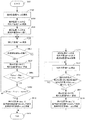
図9は本実施例における絶対位置決定のフローを示している。
絶対位置値は、ABS決定部101で決定される。
FIG. 9 shows a flow for determining the absolute position in this embodiment.
The absolute position value is determined by the
S901で処理を開始し、S902に進む。
S902では、相対位置値Pinccを初期化しS903に進む。以下、S902における絶対位置を相対位置の初期位置とし、初期位置からの相対位置変位量として相対位置値Pinccが更新される。S903に進む。
The process starts in S901 and proceeds to S902.
In S902, the relative position value Pincc is initialized and the process proceeds to S903. Hereinafter, the absolute position in S902 is set as the initial position of the relative position, and the relative position value Pincc is updated as the relative position displacement amount from the initial position. Proceed to S903.
S903では、現在の相対位置値Pinccを、現在位置(位置1)における相対位置値Pinc1として保持し、S904に進む。
S904では、現在位置(位置1)における絶対位置値Pabsを演算し、演算された絶対位置値Pabsを絶対位置値Pabs1として保持し、S905に進む。
S905では、現在位置における相対位置値Pinccを更新し、S906に進む。
In S903, the current relative position value Pincc is held as the relative position value Pinc1 at the current position (position 1), and the process proceeds to S904.
In S904, the absolute position value Pabs at the current position (position 1) is calculated, the calculated absolute position value Pabs is held as the absolute position value Pabs1, and the process proceeds to S905.
In S905, the relative position value Pincc at the current position is updated, and the process proceeds to S906.
S906では、更新された相対位置値Pinccより、位置1又は後述の絶対位置値Pabsc演算位置から所定移動量Mpbだけ移動していなければS905に戻り、移動していればS907に進む。ここで所定移動量Mpbは、最小移動量Lmsmin以下の任意の値である。
S907では、現在位置における絶対位置値Pabsを演算し、演算された絶対位置値Pabsを絶対位置値Pabsc´として保持し、S908に進む。
S908では、現在位置の絶対位置値Pabsc´と位置1での絶対位置値Pabs1との差が、現在位置の相対位置値Pinccと位置1での相対位置値Pinc1との差と一致していたらS909へ、一致していなければS911へ進む。
In S906, if it has not moved from the updated relative position value Pincc by a predetermined movement amount Mpb from
In S907, the absolute position value Pabs at the current position is calculated, the calculated absolute position value Pabs is held as the absolute position value Pabsc ′, and the process proceeds to S908.
In S908, if the difference between the absolute position value Pabsc ′ at the current position and the absolute position value Pabs1 at the
ここで絶対位置値の差と相対位置値の差とが一致していなければ、現在位置または位置1のいずれかの絶対位置値の演算に異常が発生したと判断できる。つまり、現在位置におけるパターン読み取り範囲801内又は位置1におけるパターン読み取り範囲801内のどこかに異物802があると判断できる。
Here, if the difference between the absolute position values and the difference between the relative position values do not match, it can be determined that an abnormality has occurred in the calculation of the absolute position value of either the current position or the
S909では、相対位置値Pinccから、現在位置が位置1から最小移動量Lmsmin以上移動したか否かを判断し、最小移動量Lmsmin以上移動した場合はS910に進む。最小移動量Lmsmin以上移動していない場合はS905に戻る。
S910では、最小移動量Lmsmin以上移動しても絶対位置値Pabsに異常が検出されなかったので、絶対位置値Pabsc´を基準絶対位置値Pabsbとして決定する。更に、現在の相対位置値Pinccを基準相対位置値Pincbとして保持しS916に進み、処理を終了する。
In S909, it is determined from the relative position value Pincc whether or not the current position has moved more than the minimum movement amount Lmsmin from the
In S910, since no abnormality is detected in the absolute position value Pabs even when the movement is greater than the minimum movement amount Lmsmin, the absolute position value Pabsc ′ is determined as the reference absolute position value Pabsb. Further, the current relative position value Pincc is held as the reference relative position value Pincb, the process proceeds to S916, and the process is terminated.
S908から分岐したS911では、現在位置における相対位置値Pinccを位置2における相対位置値Pinc2として保持する。更に現在位置における絶対位置値Pabsc´を位置2における絶対位置値Pabs2として保持し、S912に進む。
In S911 branched from S908, the relative position value Pincc at the current position is held as the relative position value Pinc2 at
S912では、現在位置における相対位置値Pinccを更新し、S913に進む。
S913では、相対位置値Pinccと相対位置値Pinc1との差がLmsmin以上で且つ相対位置値Pinccと相対位置値Pinc2との差がLmsmin以上の時にS914に進む。相対位置値Pinccと相対位置値Pinc1との差がLmsmin以上で且つ相対位置値Pinccと相対位置値Pinc2との差がLmsmin以上でなければS912に戻る。
In S912, the relative position value Pincc at the current position is updated, and the process proceeds to S913.
In S913, when the difference between the relative position value Pincc and the relative position value Pinc1 is Lmsmin or more and the difference between the relative position value Pincc and the relative position value Pinc2 is Lmsmin or more, the process proceeds to S914. If the difference between the relative position value Pincc and the relative position value Pinc1 is not less than Lmsmin and the difference between the relative position value Pincc and the relative position value Pinc2 is not more than Lmsmin, the process returns to S912.
S914では、現在位置における絶対位置値Pabsを演算し、演算された絶対位置値Pabsを絶対位置値Pabsc´として保持し、S915に進む。
S915では、異常発生位置から最小移動量Lmsmin以上移動し、パターン読み取り範囲801から異物802の影響はない位置であると判断し、絶対位置値Pabsc´を基準絶対位置値Pabsbとして決定し、S916に進む。
S916に進むと、処理を終了する。
In S914, the absolute position value Pabs at the current position is calculated, the calculated absolute position value Pabs is held as the absolute position value Pabsc ′, and the process proceeds to S915.
In S915, it is determined that the position moves from the abnormality occurrence position by the minimum movement amount Lmsmin and is not affected by the
When the process proceeds to S916, the process is terminated.
以後、基準絶対位置値Pabsbと基準相対位置値Pincbと現在の相対位置値Pinccを元に現在の絶対位置値Pabscを決定する。現在の絶対位置値Pabscは式(21)のように表わされる。
Pabsc = Pabsb + (Pincc - Pincb) ・・・(21)
Thereafter, the current absolute position value Pabsc is determined based on the reference absolute position value Pabsb, the reference relative position value Pincb, and the current relative position value Pincc. The current absolute position value Pabsc is expressed as shown in Equation (21).
Pabsc = Pabsb + (Pincc-Pincb) (21)
本実施例の位置検出装置は、装置の起動直後の何らかの操作による微小な量の可動部材の移動がなされると、その時点において自ずと絶対位置が確定される。
本実施例では、絶対位置値と相対位置値との関係の不一致が発生した場合、最小移動量Lmsmin以上移動した絶対位置における絶対位置値Pabsを基準絶対位置Pabsbとして決定した。
In the position detection apparatus of this embodiment, when a small amount of the movable member is moved by some operation immediately after the apparatus is started, the absolute position is automatically determined at that time.
In this embodiment, when a mismatch between the absolute position value and the relative position value occurs, the absolute position value Pabs at the absolute position moved by the minimum movement amount Lmsmin is determined as the reference absolute position Pabsb.
しかし、再度絶対位置値と相対位置値との関係の不一致を確認し、不一致が発生した場合は、絶対位置値と相対位置値との関係が一致するまで基準絶対位置Pabsbを決定しない方法でも良い。 However, it is also possible to check the mismatch of the relationship between the absolute position value and the relative position value again, and if a mismatch occurs, the method of not determining the reference absolute position Pabsb until the relationship between the absolute position value and the relative position value matches. .
またお互いに最小移動量Lmsmin以上離れた複数の絶対位置における絶対位置値と相対位置値を記録し、複数の絶対位置における絶対位置値と相対位置値の関係から、関係の一致が多い絶対位置値を元に基準絶対位置値を決定しても良い。 Also, absolute position values and relative position values at a plurality of absolute positions that are separated from each other by at least the minimum movement amount Lmsmin are recorded, and the absolute position values that have a large number of matching relationships from the relationship between absolute position values and relative position values at a plurality of absolute positions The reference absolute position value may be determined based on the above.
以上により、バーニア型アブソリュートエンコーダにおいて、スケール上にゴミやキズがある場合でも、誤った絶対位置演算を防ぐことを可能とした、信頼性の高い絶対位置を演算することができる。 As described above, in the vernier type absolute encoder, even when dust or scratches are present on the scale, it is possible to calculate an absolute position with high reliability that can prevent an erroneous absolute position calculation.
また、本実施例においては、光学式のエンコーダを前提として説明したが、本発明はこれに限定されることはなく、磁気式又は静電容量式等のアブソリュートエンコーダにおいても、移動方向に周期パターンが形成されたスケール上の欠陥等で、周期信号の検出に外乱を与えるものに対して、同様の効果を奏することができる。 In the present embodiment, the description has been made on the assumption that the optical encoder is used. However, the present invention is not limited to this, and a periodic pattern in the moving direction is also used in an absolute encoder such as a magnetic type or a capacitance type. The same effect can be obtained for a defect on the scale on which the signal is formed that gives disturbance to the detection of the periodic signal.
次に、図10を用いて、本発明の第2の実施例を説明する。
図10は本実施例の構成ブロック図であり、図1と同様の構成のものは同符号を付す。
Next, a second embodiment of the present invention will be described with reference to FIG.
FIG. 10 is a block diagram showing the configuration of the present embodiment. Components having the same configurations as those in FIG.
ABS決定部1001は、ABS/INC演算部102が演算した絶対位置値Pabs及び相対位置値Pincを元に、現在の絶対位置Pabscを決定する絶対位置決定部であり、実施例1で説明したABS決定部101とは動作が異なる。駆動制御部1002は可動要素1004の駆動制御を行う駆動制御部である。モータ1003は可動要素1004を駆動させるモータであり、例えばDCモータやステッピングモータである。可動要素1004はABSセンサー104の絶対位置検出対象となる可動要素である。
The
次に本実施例の動作について説明する。
図11は本実施例における絶対位置決定のフローを示している。
絶対位置値は、ABS決定部1001で決定される。
Next, the operation of this embodiment will be described.
FIG. 11 shows the flow of absolute position determination in this embodiment.
The absolute position value is determined by the
S1101で処理を開始し、S1102に進む。
S1102では、相対位置値Pinccを初期化し、S1103に進む。以下S1102における絶対位置を相対位置の初期位置として、初期位置からの相対位置変位量として相対位置値Pinccが更新される。
S1103では、現在の相対位置値Pinccを現在位置(位置1)における相対位置値Pinc1として保持し、S1104に進む。
The process starts in S1101, and proceeds to S1102.
In S1102, the relative position value Pincc is initialized, and the process proceeds to S1103. Thereafter, the relative position value Pincc is updated as the relative position displacement amount from the initial position with the absolute position in S1102 as the initial position of the relative position.
In S1103, the current relative position value Pincc is held as the relative position value Pinc1 at the current position (position 1), and the process proceeds to S1104.
S1104では、現在位置(位置1)における絶対位置値Pabsを演算する。演算された絶対位置値Pabsを絶対位置値Pabs1として保持し、S1105に進む。
S1105では、ABS決定部1001は、駆動制御部1002に対して、所定移動量Mpb分、可動要素1004を駆動する指令を行い、S1106に進む。ここで所定移動量Mpbは、最小移動量Lmsmin以下の任意の値となる。駆動制御部1002は指令に応じて、モータ1003を制御し、可動要素1004を駆動する。可動要素1004の駆動に応じて、ABSセンサー104は可動要素1004の位置に応じた信号をAD変換部105に出力する。
In S1104, the absolute position value Pabs at the current position (position 1) is calculated. The calculated absolute position value Pabs is held as the absolute position value Pabs1, and the process proceeds to S1105.
In S1105, the
S1106では、現在位置における相対位置値Pinccを更新し、S1107に進む。
S1107では、更新された相対位置値Pinccより、位置1又は後述の絶対位置値Pabsc演算位置から所定移動量Mpbだけ移動していなければS1106に戻り、移動していればS1108に進む。
S1108では、現在位置における絶対位置値Pabsを演算する。演算した絶対位置値Pabsを絶対位置値Pabsc´として保持し、S1109に進む。
In S1106, the relative position value Pincc at the current position is updated, and the process proceeds to S1107.
In S1107, if it has not moved from
In S1108, the absolute position value Pabs at the current position is calculated. The calculated absolute position value Pabs is held as the absolute position value Pabsc ′, and the process proceeds to S1109.
S1109では、現在位置の絶対位置値Pabsc´と位置1の絶対位置値Pabs1との差が、現在位置の相対位置値Pinccと位置1での相対位置値Pinc1との差と一致していたらS1110へ、一致していなければS1112へ進む。
S1110では、相対位置値Pinccから、現在位置が位置1から最小移動量Lmsmin以上移動したか否かを判断し、最小移動量Lmsmin以上移動した場合はS1111に進む。最小移動量Lmsmin以上移動していない場合はS1105に戻る。
In S1109, if the difference between the absolute position value Pabsc 'at the current position and the absolute position value Pabs1 at
In S1110, it is determined from the relative position value Pincc whether or not the current position has moved more than the minimum movement amount Lmsmin from the
S1111では、最小移動量Lmsmin以上移動しても絶対位置値Pabsに異常が検出されなかったので、絶対位置値Pabsc´を基準絶対位置値Pabsbとして決定する。更に、現在の相対位置値Pinccを基準相対位置値Pincbとして保持しS1118に進む。
S1112では、現在位置における相対位置値Pinccを位置2における相対位置値Pinc2として保持する。更に現在位置における絶対位置値Pabsc´を位置2における絶対位置値Pabs2として保持し、S1113に進む。
In S1111, since no abnormality is detected in the absolute position value Pabs even if the movement is greater than the minimum movement amount Lmsmin, the absolute position value Pabsc ′ is determined as the reference absolute position value Pabsb. Further, the current relative position value Pincc is held as the reference relative position value Pincb, and the process proceeds to S1118.
In S1112, the relative position value Pincc at the current position is held as the relative position value Pinc2 at
S1113では、ABS決定部1001は、駆動制御部1002に対して、最小移動量Lmsmin分だけ可動要素1004を駆動する指令を行い、S1114に進む。
S1114では、現在位置における相対位置値Pinccを更新し、S1115に進む。
S1115では、相対位置値Pinccと相対位置値Pinc1との差がLmsmin以上で且つ相対位置値Pinccと相対位置値Pinc2との差がLmsmin以上の時にS1116に進む。相対位置値Pinccと相対位置値Pinc1との差がLmsmin以上で且つ相対位置値Pinccと相対位置値Pinc2との差がLmsmin以上でなければS1114に戻る。
In S1113, the
In S1114, the relative position value Pincc at the current position is updated, and the process proceeds to S1115.
In S1115, when the difference between the relative position value Pincc and the relative position value Pinc1 is equal to or greater than Lmsmin and the difference between the relative position value Pincc and the relative position value Pinc2 is equal to or greater than Lmsmin, the process proceeds to S1116. If the difference between the relative position value Pincc and the relative position value Pinc1 is not less than Lmsmin and the difference between the relative position value Pincc and the relative position value Pinc2 is not more than Lmsmin, the process returns to S1114.
S1116では、現在位置における絶対位置値Pabsを演算する。演算した絶対位置値Pabsを絶対位置値Pabsc´として保持し、S1117に進む。
S1117では、異常発生位置から最小移動量Lmsmin以上移動し、パターン読み取り範囲801から異物802の影響がない位置であると判断し、絶対位置値Pabsc´を基準絶対位置値Pabsbとして決定し、S1118に進む。
S1118では、ABS決定部1001は、駆動制御部1002に対して、初期位置である相対位置値Pinc1へ可動要素1004を駆動させるように指令を行い、S1119に進む。
In S1116, the absolute position value Pabs at the current position is calculated. The calculated absolute position value Pabs is held as the absolute position value Pabsc ′, and the process proceeds to S1117.
In S1117, it is determined that the position moves from the abnormality occurrence position by the minimum movement amount Lmsmin and is not affected by the
In S1118, the
S1119では、現在位置における相対位置値Pinccを更新し、S1120に進む。
S1120では、相対位置値Pinccと相対位置値Pinc1とが一致していればS1121に進み処理を終了する。一致していなければS1119に戻る。
In S1119, the relative position value Pincc at the current position is updated, and the process proceeds to S1120.
In S1120, if the relative position value Pincc and the relative position value Pinc1 match, the process proceeds to S1121 and the process is terminated. If they do not match, the process returns to S1119.
以後、実施例1と同様の方法で、基準絶対位置値Pabsbと基準相対位置値Pincbと現在の相対位置値Pinccを元に現在の絶対位置値Pabscを決定する。 Thereafter, the current absolute position value Pabsc is determined based on the reference absolute position value Pabsb, the reference relative position value Pincb, and the current relative position value Pincc by the same method as in the first embodiment.
上記の処理フローにおいて、S1118に進む時点において、絶対位置は確定している。本実施例においては、絶対位置を確定するために強制的に可動部材を移動させるため、S1118からS1120の処理は本処理フローの開始前の状態に戻すための処理である。このために、図11の処理フローの開始直後の相対位置値を保存する手段を有するようにしてもよい。本実施例では、絶対位置値と相対位置値との関係の不一致が発生した場合、最小移動量Lmsmin以上移動した絶対位置における絶対位置値Pabsを基準絶対位置Pabsbとして決定した。 In the above processing flow, the absolute position is fixed at the time of proceeding to S1118. In the present embodiment, since the movable member is forcibly moved to determine the absolute position, the processing from S1118 to S1120 is processing for returning to the state before the start of this processing flow. For this purpose, a means for storing the relative position value immediately after the start of the processing flow of FIG. 11 may be provided. In this embodiment, when a mismatch between the absolute position value and the relative position value occurs, the absolute position value Pabs at the absolute position moved by the minimum movement amount Lmsmin is determined as the reference absolute position Pabsb.
しかし、再度絶対位置値と相対位置値との関係の不一致を確認し、不一致が発生した場合は、再度最小移動量Lmsmin以上駆動し、絶対位置値と相対位置値との関係が一致するまで、基準絶対位置Pabsbを決定しない方法でも良い。 However, once again confirming the mismatch in the relationship between the absolute position value and the relative position value, if a mismatch occurs, drive again over the minimum movement amount Lmsmin until the relationship between the absolute position value and the relative position value matches. A method in which the reference absolute position Pabsb is not determined may be used.
また、それぞれが最小移動量Lmsmin以上離れた複数位置に可動要素1004を駆動し、それぞれの位置における絶対位置値及び相対位置値を行う。その後、複数の絶対位置における絶対位置値と相対位置値の関係から、関係の一致が多い絶対位置値を元に基準絶対位置値を決定しても良い。
以上により、バーニア型アブソリュートエンコーダにおいて、スケール上にゴミやキズがある場合でも、初期起動時において最小限の駆動により、誤った絶対位置演算を防ぐことを可能とした、信頼性の高い絶対位置を演算することができる。
Further, the
As described above, in the vernier type absolute encoder, even if there is dust or scratches on the scale, the absolute position with high reliability that can prevent the wrong absolute position calculation by the minimum drive at the initial start-up. It can be calculated.
また、上記の実施例においては、エンコーダとして光学式のエンコーダを使用する実施例を例示したが、本発明はこれに限定されるものではなく、磁気式或いは静電容量式のエンコーダを使用してもよい。 In the above embodiment, the optical encoder is used as the encoder. However, the present invention is not limited to this, and a magnetic or capacitive encoder is used. Also good.
上記の実施例の位置検出装置を、可動光学部材を有するレンズ装置に適用し、可動光学部材の位置を検出するように構成することで、本発明の効果を享受することができるレンズ装置を実現することができる。また、上記の実施例の位置検出装置を、可動光学部材を有するレンズ装置及びカメラ装置を備える撮影装置に適用し、可動光学部材の位置を検出するように構成することで、本発明の効果を享受することができる撮影装置を実現することができる。 By applying the position detection device of the above-described embodiment to a lens device having a movable optical member and detecting the position of the movable optical member, a lens device that can enjoy the effects of the present invention is realized. can do. In addition, the position detection device of the above embodiment is applied to a photographing device including a lens device having a movable optical member and a camera device, and configured to detect the position of the movable optical member. An imaging device that can be enjoyed can be realized.
101 ABS決定部
102 ABS/INC演算部
103 読取パターン切替え部
104 ABSセンサー
1001 ABS決定部
101
Claims (10)
前記第1要素および前記第2要素のうちの他方に備えられ、前記複数のパターン列に対応する複数の信号を取得するセンサと、
前記複数の信号に基づいて、前記第1要素および前記第2要素のうちの一方に対する前記第1要素および前記第2要素のうちの他方の位置を得、前記複数の信号のうちの1つ以上の信号に基づいて、前記他方の位置に対する変位量を得る処理部と、
を有し、
前記処理部は、前記他方の位置として得られた第一位置と、前記第一位置とは異なる、前記他方の位置として得られた第二位置との差と、前記第一位置に対する前記第二位置での前記変位量とに基づく、前記第二位置を前記変位量の基準位置とするかの判断を行い、前記第二位置を前記基準位置としないと判断した場合には、前記第一位置および前記第二位置とは設定量以上離れた、前記他方の位置として得られた第三位置を前記基準位置とする、ことを特徴とする位置検出装置。 A scale provided in one of the first element and the second element and having a plurality of pattern rows formed at different periods;
Provided to the other of said first element and said second element, a sensor for acquiring a plurality of signals corresponding to said plurality of pattern rows,
Obtaining the position of the other of the first element and the second element relative to one of the first element and the second element based on the plurality of signals, and one or more of the plurality of signals A processing unit for obtaining a displacement amount with respect to the other position based on the signal of
Have
Wherein the processing unit includes a first position location obtained as the position of the other, the first is different from the ones location, the difference between the second-largest location obtained as the position of the other, the first of location the displacement amount and based Dzu rather in the second position with respect to, the second position do judgment as a reference position of the displacement, if the second position is determined not to the reference position The position detection apparatus is characterized in that the first position and the second position are separated from each other by a set amount or more and the third position obtained as the other position is set as the reference position .
前記第1要素および前記第2要素のうちの他方に備えられ、前記複数のパターン列に対応する複数の信号を取得するセンサと、
前記複数の信号に基づいて、前記第1要素および前記第2要素のうちの一方に対する前記第1要素および前記第2要素のうちの他方の位置を得、前記複数の信号のうちの1つ以上の信号に基づいて、前記他方の位置に対する変位量を得る処理部と、
を有し、
前記処理部は、前記他方の位置として得られた第一位置と、前記第一位置とは異なる、前記他方の位置として得られた第二位置との差と、前記第一位置に対する前記第二位置での前記変位量とに基づく、前記第二位置を前記変位量の基準位置とするかの判断を行い、前記第二位置を前記基準位置としないと判断した場合には、前記第一位置および前記第二位置とは設定量以上離れた、前記他方の位置として得られた第三位置を前記基準位置とするかの判断を行い、前記第三位置を前記基準位置とするかの判断は、前記第三位置と前記第一位置との差と、前記第一位置に対する前記第三位置での前記変位量とに基づく、前記第三位置を前記基準位置とするかの判断、および前記第三位置と前記第二位置との差と、前記第二位置に対する前記第三位置での前記変位量とに基づく、前記第三位置を前記基準位置とするかの判断のうち少なくとも一方を行うことを特徴とする位置検出装置。 A scale provided in one of the first element and the second element and having a plurality of pattern rows formed at different periods;
Provided to the other of said first element and said second element, a sensor for acquiring a plurality of signals corresponding to said plurality of pattern rows,
Obtaining the position of the other of the first element and the second element relative to one of the first element and the second element based on the plurality of signals, and one or more of the plurality of signals A processing unit for obtaining a displacement amount with respect to the other position based on the signal of
Have
Wherein the processing unit includes a first position location obtained as the position of the other, the first is different from the ones location, the difference between the second-largest location obtained as the position of the other, the first of location based on said displacement of amount in the second position with respect to, the second position do judgment as a reference position of the displacement, when the second position is determined not to the reference position And determining whether the third position obtained as the other position, which is separated from the first position and the second position by a predetermined amount or more, is the reference position, and the third position is the reference position. Whether the third position is set as the reference position is determined based on the difference between the third position and the first position and the amount of displacement at the third position with respect to the first position. Determining, the difference between the third position and the second position, and the third position relative to the second position; Based on the above amount of displacement location, the position detecting device, wherein said third position to perform at least one of either the judgment is the reference position.
前記制御部は、前記他方の位置を変更するように前記駆動を制御する、
ことを特徴とする請求項1乃至4のいずれか1項に記載の位置検出装置。 A control unit for controlling one of the drive of the movable one of said first element and said second element,
Wherein the control unit controls the drive so as to change the position of the other,
The position detection device according to claim 1, wherein the position detection device is a first position detection device.
ことを特徴とする請求項5に記載の位置検出装置。 Before SL controller, said second position or the third position after the reference position of the displacement amount, and controls the drive to return the one of the movable to its initial position,
The position detection device according to claim 5.
Priority Applications (3)
| Application Number | Priority Date | Filing Date | Title |
|---|---|---|---|
| JP2013224847A JP6334892B2 (en) | 2013-10-30 | 2013-10-30 | POSITION DETECTION DEVICE AND LENS DEVICE AND PHOTOGRAPHING DEVICE HAVING THE SAME |
| DE102014016060.2A DE102014016060B4 (en) | 2013-10-30 | 2014-10-29 | Position detecting device and lens device and image pick-up device including the same |
| US14/527,817 US9435667B2 (en) | 2013-10-30 | 2014-10-30 | Position detecting apparatus, and lens apparatus and image pickup apparatus including the position detecting apparatus |
Applications Claiming Priority (1)
| Application Number | Priority Date | Filing Date | Title |
|---|---|---|---|
| JP2013224847A JP6334892B2 (en) | 2013-10-30 | 2013-10-30 | POSITION DETECTION DEVICE AND LENS DEVICE AND PHOTOGRAPHING DEVICE HAVING THE SAME |
Publications (3)
| Publication Number | Publication Date |
|---|---|
| JP2015087193A JP2015087193A (en) | 2015-05-07 |
| JP2015087193A5 JP2015087193A5 (en) | 2016-12-15 |
| JP6334892B2 true JP6334892B2 (en) | 2018-05-30 |
Family
ID=52811813
Family Applications (1)
| Application Number | Title | Priority Date | Filing Date |
|---|---|---|---|
| JP2013224847A Active JP6334892B2 (en) | 2013-10-30 | 2013-10-30 | POSITION DETECTION DEVICE AND LENS DEVICE AND PHOTOGRAPHING DEVICE HAVING THE SAME |
Country Status (3)
| Country | Link |
|---|---|
| US (1) | US9435667B2 (en) |
| JP (1) | JP6334892B2 (en) |
| DE (1) | DE102014016060B4 (en) |
Families Citing this family (3)
| Publication number | Priority date | Publication date | Assignee | Title |
|---|---|---|---|---|
| JP6533360B2 (en) * | 2013-10-30 | 2019-06-19 | キヤノン株式会社 | Position detection device, lens apparatus having the same, and imaging apparatus |
| JP6739911B2 (en) | 2015-09-04 | 2020-08-12 | キヤノン株式会社 | Position detection device, lens device, and imaging device |
| US11874144B2 (en) * | 2020-07-28 | 2024-01-16 | Li Lin | Displacement measurement system |
Family Cites Families (15)
| Publication number | Priority date | Publication date | Assignee | Title |
|---|---|---|---|---|
| US5260568A (en) * | 1990-07-18 | 1993-11-09 | Okuma Corporation | Absolute position detector with diffraction grating windows and spot position detection |
| JP2593257B2 (en) | 1991-08-12 | 1997-03-26 | 株式会社ミツトヨ | Displacement measuring device |
| JPH08304113A (en) | 1995-05-09 | 1996-11-22 | Yokogawa Electric Corp | Vernier type absolute encoder |
| JPH10253393A (en) * | 1997-03-10 | 1998-09-25 | Yaskawa Electric Corp | Absolute encoder |
| JP4146133B2 (en) | 2002-02-14 | 2008-09-03 | オークマ株式会社 | Linear encoder |
| JP4924878B2 (en) | 2006-11-06 | 2012-04-25 | 株式会社ニコン | Absolute encoder |
| JP5286584B2 (en) * | 2007-06-19 | 2013-09-11 | 株式会社ミツトヨ | Absolute position measuring encoder |
| JP2011058988A (en) * | 2009-09-11 | 2011-03-24 | Mitsutoyo Corp | Displacement detector, displacement detection method, and displacement detecting program |
| JP5408342B2 (en) * | 2010-04-02 | 2014-02-05 | 株式会社安川電機 | Encoder, drive device, absolute position calculation method, and encoder manufacturing method |
| JP5595148B2 (en) * | 2010-07-05 | 2014-09-24 | キヤノン株式会社 | Absolute encoder |
| JP5639421B2 (en) | 2010-09-13 | 2014-12-10 | キヤノン株式会社 | Position detection apparatus and position detection method using an encoder |
| EP2477006A1 (en) * | 2011-01-17 | 2012-07-18 | Thomas Baader | High resolution absolute linear encoder |
| JP2012173168A (en) | 2011-02-22 | 2012-09-10 | Iai:Kk | Encoder and actuator |
| JP6071181B2 (en) * | 2011-10-14 | 2017-02-01 | キヤノン株式会社 | Encoder and device equipped with the same |
| JP2013246054A (en) | 2012-05-25 | 2013-12-09 | Canon Inc | Motor control device, and control method of motor control device |
-
2013
- 2013-10-30 JP JP2013224847A patent/JP6334892B2/en active Active
-
2014
- 2014-10-29 DE DE102014016060.2A patent/DE102014016060B4/en active Active
- 2014-10-30 US US14/527,817 patent/US9435667B2/en active Active
Also Published As
| Publication number | Publication date |
|---|---|
| JP2015087193A (en) | 2015-05-07 |
| US20150116571A1 (en) | 2015-04-30 |
| US9435667B2 (en) | 2016-09-06 |
| DE102014016060A1 (en) | 2015-04-30 |
| DE102014016060B4 (en) | 2021-04-29 |
Similar Documents
| Publication | Publication Date | Title |
|---|---|---|
| US5956659A (en) | Arrangement and method for the automatic correction of error-containing scanning signals of incremental position-measuring devices | |
| JP6207208B2 (en) | Position detection means | |
| JP6422201B2 (en) | Position detection means | |
| JP5837201B2 (en) | Method and apparatus for determining position | |
| US8941051B2 (en) | Photosensor for position detecting device, position detecting device using same and position detecting method | |
| EP2848898B1 (en) | Encoder and apparatus using encoder | |
| JP5755009B2 (en) | Encoder | |
| JP5791340B2 (en) | Encoder | |
| EP2581713B1 (en) | Encoder and apparatus using the same | |
| US8912929B2 (en) | Correction value derivation apparatus, displacement amount derivation apparatus, control apparatus, and correction value derivation method | |
| JP6334892B2 (en) | POSITION DETECTION DEVICE AND LENS DEVICE AND PHOTOGRAPHING DEVICE HAVING THE SAME | |
| JP6533360B2 (en) | Position detection device, lens apparatus having the same, and imaging apparatus | |
| JP5128368B2 (en) | Scale and encoder for encoder | |
| JP6313571B2 (en) | POSITION DETECTION DEVICE AND LENS DEVICE AND PHOTOGRAPHING DEVICE HAVING THE SAME | |
| JP2006214929A (en) | Optical encoder | |
| JP6289192B2 (en) | POSITION DETECTION DEVICE, LENS DEVICE HAVING SAME, AND OPTICAL OPERATING DEVICE | |
| JP6150462B2 (en) | Position detection encoder and apparatus using the same | |
| JP6308739B2 (en) | POSITION DETECTION DEVICE, LENS DEVICE HAVING THE SAME, IMAGE READING DEVICE, AND IMAGE FORMING DEVICE | |
| JP2006329755A (en) | Encoder origin signal generating method and device | |
| US10623895B2 (en) | Position detection apparatus for detecting position of first member relative to second member, and lens apparatus, image pickup apparatus, and lens command apparatus each including the position detection apparatus | |
| JP2015045594A5 (en) | ||
| JP2013234852A (en) | Position detecting encoder and device using the same | |
| JP5747342B2 (en) | Optical encoder | |
| JP6746643B2 (en) | Position detection device, lens device, imaging device, and command device | |
| JP2861712B2 (en) | Linear encoder |
Legal Events
| Date | Code | Title | Description |
|---|---|---|---|
| A521 | Request for written amendment filed |
Free format text: JAPANESE INTERMEDIATE CODE: A523 Effective date: 20161027 |
|
| A621 | Written request for application examination |
Free format text: JAPANESE INTERMEDIATE CODE: A621 Effective date: 20161027 |
|
| A977 | Report on retrieval |
Free format text: JAPANESE INTERMEDIATE CODE: A971007 Effective date: 20170727 |
|
| A131 | Notification of reasons for refusal |
Free format text: JAPANESE INTERMEDIATE CODE: A131 Effective date: 20170831 |
|
| A521 | Request for written amendment filed |
Free format text: JAPANESE INTERMEDIATE CODE: A523 Effective date: 20171030 |
|
| RD05 | Notification of revocation of power of attorney |
Free format text: JAPANESE INTERMEDIATE CODE: A7425 Effective date: 20171214 |
|
| RD04 | Notification of resignation of power of attorney |
Free format text: JAPANESE INTERMEDIATE CODE: A7424 Effective date: 20180126 |
|
| TRDD | Decision of grant or rejection written | ||
| A01 | Written decision to grant a patent or to grant a registration (utility model) |
Free format text: JAPANESE INTERMEDIATE CODE: A01 Effective date: 20180329 |
|
| A61 | First payment of annual fees (during grant procedure) |
Free format text: JAPANESE INTERMEDIATE CODE: A61 Effective date: 20180427 |
|
| R151 | Written notification of patent or utility model registration |
Ref document number: 6334892 Country of ref document: JP Free format text: JAPANESE INTERMEDIATE CODE: R151 |