HINTERGRUND DER ERFINDUNGBACKGROUND OF THE INVENTION
Gebiet der ErfindungField of the invention
Die vorliegende Erfindung bezieht sich auf eine Positionsdetektiervorrichtung, die konfiguriert ist, eine Position eines beweglichen Elements zu detektieren, sowie auf eine Linsenvorrichtung und eine Bildaufnahmevorrichtung, die die Positionsdetektiervorrichtung beinhalten.The present invention relates to a position detecting device configured to detect a position of a movable member, and a lens device and an image pickup device including the position detecting device.
Beschreibung des Standes der TechnikDescription of the prior art
Als eine Vorrichtung zum Messen einer Bewegungsdistanz eines Objekts ist bisher neben einem Inkrementalgeber zum Messen einer Relativbewegungsdistanz ein Absolutwertgeber bekannt, der eine Absolutposition zu detektieren vermag.As a device for measuring a movement distance of an object, in addition to an incremental encoder for measuring a relative movement distance, an absolute value encoder which is able to detect an absolute position has been known.
Die japanische Patentanmeldung Nr. H08-304113 offenbart einen Absolutwertgeber des Noniustyps. Der in der japanischen Patentanmeldung Nr. H08-304113 offenbarte Absolutwertgeber des Noniustyps besitzt eine Anordnung, die mindestens zwei verschiedene Anordnungsabstände auf einer Spur besitzende Gitterraster beinhaltet. Basierend auf einer geringen Verschiebung zwischen detektierten Signalen, die aufgrund eines Unterschieds im Anordnungsabstand zwischen den Gitterrastern erzeugt wird, wird eine Position in einem Abschnitt identifiziert, über dem der Absolutwertgeber des Noniustyps einmal umläuft, (hiernach auch als „Absolutpositionsdetektion“ oder „Absolutpositionsberechnung“ bezeichnet).Japanese Patent Application No. H08-304113 discloses a vernier type absolute encoder. The method disclosed in Japanese Patent Application No. H08-304113 disclosed absolute encoder of the vernier type has an arrangement which includes at least two different arrangement spacings on a track having grating grids. Based on a slight shift between detected signals, which is generated due to a difference in the spacing between the grids, a position is identified in a section over which the absolute encoder of the vernier type rotates once (hereinafter also referred to as "absolute position detection" or "absolute position calculation" ).
Die japanische Patentanmeldung Nr. H05-45151 offenbart ein Umschalttiming in eine Absolutzähloperation im Absolutwertgeber des Noniustyps. Der Absolutwertgeber des Noniustyps besitzt eine Anordnung, in der Spurraster mit kleineren Anordnungsabständen und mit größeren Anordnungsabständen ausgebildet sind. Als das Umschalttiming in die auf den oben beschriebenen Spuren basierende Absolutzähloperation wird eine Operation vom Absolutwertgeber des Noniustyps in die Absolutzähloperation umgeschaltet, wenn eine Geschwindigkeit zu einer Geschwindigkeit verringert wird, bei der fehlerhafte Detektion bei einer Inkrementalmessung bei den kleineren Anordnungsabständen nicht auftritt.Japanese Patent Application No. H05-45151 discloses a switching timing into an absolute counting operation in the absolute encoder of the vernier type. The vernier type absolute encoder has an arrangement in which track grids are formed with smaller spacings and with larger spacings. As the switching timing to the absolute counting operation based on the above-described tracks, an operation from the vernier type absolute encoder is switched to the absolute counting operation when a speed is decreased to a speed at which erroneous detection does not occur in incremental measurement at the smaller spacing.
Jedoch weist der in der japanischen Patentanmeldung Nr. H08-304113 offenbarte Absolutwertgeber das folgende Problem auf. Falls Staubpartikel und Kratzer auf einer Skala vorhanden sind, wird eine Absolutposition basierend auf einem fehlerhaften Detektionssignal berechnet. Als Ergebnis tritt dort das Problem auf, dass eine korrekte Absolutposition nicht berechnet werden kann.However, the method disclosed in Japanese Patent Application No. H08-304113 disclosed absolute encoders the following problem. If there are dust particles and scratches on a scale, an absolute position is calculated based on an erroneous detection signal. As a result, there arises a problem that a correct absolute position cannot be calculated.
Weiterhin weist der in der japanischen Patentanmeldung Nr. H05-45151 offenbarte Absolutwertgeber das folgende Problem auf. Falls Staubpartikel und Kratzer auf einer Skala an einer Position vorhanden sind, bei der die Geschwindigkeit verringert wird, damit fehlerhafte Detektion bei Inkrementalmessung mit feinen Anordnungsabständen nicht auftritt, wird ein fehlerhaftes Detektionssignal detektiert. Als Ergebnis wird auch eine Absolutposition basierend auf dem fehlerhaften Detektionssignal berechnet. Die Offenlegungsschrift EP 2 312 273 A2 zeigt einen Detektor, der einen Versatz relativ zu einer Skala messen kann. Die Offenlegungsschrift US 2013/0 020 917 A1 zeigt einen Codierer mit einer Positionsdaten-Erhalteeinheit. Die Offenlegungsschrift US 2013/0 099 105 A1 zeigt einen Codierer, der eine Skala mit einem ersten und zweiten periodischen Raster beinhaltet. Die Offenlegungsschrift US 2008/0 315 076 A1 zeigt eine Skala mit einer ersten und zweiten inkrementalen Spur und einer Absolut-Spur.Furthermore, the method disclosed in Japanese Patent Application No. H05-45151 disclosed absolute encoders the following problem. If there are dust particles and scratches on a scale at a position at which the speed is reduced so that erroneous detection does not occur in incremental measurement with fine spacing, an erroneous detection signal is detected. As a result, an absolute position is also calculated based on the erroneous detection signal. The disclosure document EP 2 312 273 A2 shows a detector that can measure an offset relative to a scale. The disclosure document US 2013/0 020 917 A1 Fig. 10 shows an encoder with a position data obtaining unit. The disclosure document US 2013/0 099 105 A1 Figure 3 shows an encoder incorporating a scale with first and second periodic grids. The disclosure document US 2008/0 315 076 A1 shows a scale with a first and second incremental track and an absolute track.
OFFENBARUNG DER ERFINDUNGDISCLOSURE OF THE INVENTION
Es ist ein Ziel der vorliegenden Erfindung eine, eine hohe Zuverlässigkeit besitzende Positionsdetektiervorrichtung des Noniustyps bereitzustellen, die fehlerhafte Absolutpositionsberechnung selbst dann zu verhindern vermag, falls Staubpartikel und Kratzer auf einer Spur vorhanden sind.It is an object of the present invention to provide a high reliability vernier type position detecting device capable of preventing erroneous absolute position calculation even if there are dust particles and scratches on a track.
Um das oben-erwähnte Ziel zu erreichen, beinhaltet eine Ausführungsform der vorliegenden Erfindung eine Positionsdetektiervorrichtung gemäß Anspruch 1.In order to achieve the above-mentioned object, an embodiment of the present invention includes a position detecting device according to claim 1.
Gemäß einer Ausführungsform der vorliegenden Erfindung kann die eine hohe Zuverlässigkeit besitzende Positionsdetektiervorrichtung bereitgestellt werden, die fehlerhafte Absolutpositionsberechnung selbst dann zu verhindern vermag, falls Staubpartikel und Kratzer auf einer Spur in der Positionsdetektiervorrichtung des Noniustyps vorhanden sind.According to an embodiment of the present invention, there can be provided the high reliability position detecting device capable of preventing erroneous absolute position calculation even if there are dust particles and scratches on a track in the vernier type position detecting device.
Weitere Merkmale der vorliegenden Erfindung werden aus der folgenden Beschreibung von Ausführungsbeispielen unter Bezugnahme auf die beigefügten Zeichnungen deutlich.Further features of the present invention will become clear from the following description of exemplary embodiments with reference to the accompanying drawings.
FigurenlisteFigure list
-
1 ist ein Anordnungsblockdiagramm gemäß einer ersten Ausführungsform der vorliegenden Erfindung. 1 Fig. 13 is a layout block diagram according to a first embodiment of the present invention.
-
2 ist eine Schnittansicht eines ABS-Sensors. 2 Fig. 3 is a sectional view of an ABS sensor.
-
3 ist eine Draufsicht einer Skaleneinheit. 3 Fig. 3 is a plan view of a scale unit.
-
4 ist eine Draufsicht eines Lichtempfängers. 4th Fig. 3 is a plan view of a light receiver.
-
5 ist ein Flussdiagramm einer Absolutpositionsberechnung. 5 Fig. 3 is a flow chart of absolute position calculation.
-
6A ist ein Graph, der erste und zweite Relativpositionssignale sowie ein Noniussignal zeigt. 6A Figure 13 is a graph showing first and second relative position signals and a vernier signal.
-
6B ist ein Graph, der erste und zweite Relativpositionssignale sowie ein Noniussignal zeigt. 6B Figure 13 is a graph showing first and second relative position signals and a vernier signal.
-
6C ist ein Graph, der erste und zweite Relativpositionssignale sowie ein Noniussignal zeigt. 6C Figure 13 is a graph showing first and second relative position signals and a vernier signal.
-
6D ist ein Graph, der erste und zweite Relativpositionssignale sowie ein Noniussignal zeigt. 6D Figure 13 is a graph showing first and second relative position signals and a vernier signal.
-
7A ist ein Graph, der eine Wellenformänderung bei Synchronismusberechnung zeigt. 7A Fig. 13 is a graph showing a waveform change upon synchronism calculation.
-
7B ist ein Graph, der eine Wellenformänderung bei Synchronismusberechnung zeigt. 7B Fig. 13 is a graph showing a waveform change upon synchronism calculation.
-
7C ist ein Graph, der eine Wellenformänderung bei Synchronismusberechnung zeigt. 7C Fig. 13 is a graph showing a waveform change upon synchronism calculation.
-
7D ist ein Graph, der eine Wellenformänderung bei Synchronismusberechnung zeigt. 7D Fig. 13 is a graph showing a waveform change upon synchronism calculation.
-
8A ist ein Diagramm, das einen Fremdkörper auf einer Skala und ein Rasterlesegebiet illustriert. 8A Fig. 13 is a diagram illustrating a foreign object on a scale and a raster reading area.
-
8B ist ein Diagramm, das einen Fremdkörper auf einer Skala und ein Rasterlesegebiet illustriert. 8B Fig. 13 is a diagram illustrating a foreign object on a scale and a raster reading area.
-
8C ist ein Diagramm, das einen Fremdkörper auf einer Skala und ein Rasterlesegebiet illustriert. 8C Fig. 13 is a diagram illustrating a foreign object on a scale and a raster reading area.
-
9 ist ein Flussdiagramm einer Absolutpositionsbestimmung gemäß der ersten Ausführungsform. 9 Fig. 13 is a flowchart of absolute position determination according to the first embodiment.
-
10 ist ein Anordnungsblockdiagramm gemäß einer zweiten Ausführungsform der vorliegenden Erfindung. 10 Fig. 13 is a layout block diagram according to a second embodiment of the present invention.
-
11 ist ein Flussdiagramm einer Absolutpositionsbestimmung gemäß der zweiten Ausführungsform. 11 Fig. 13 is a flowchart of absolute position determination according to the second embodiment.
BESCHREIBUNG DER AUSFÜHRUNGSFORMENDESCRIPTION OF THE EMBODIMENTS
Im Folgenden werden Ausführungsbeispiele der vorliegenden Erfindung unter Bezugnahme auf die begleitenden Zeichnungen im Detail beschrieben.In the following, exemplary embodiments of the present invention are described in detail with reference to the accompanying drawings.
Erste AusführungsformFirst embodiment
Im Folgenden wird eine Positionsdetektiervorrichtung gemäß einer ersten Ausführungsform der vorliegenden Erfindung unter Bezugnahme auf 1 beschrieben.In the following, a position detecting device according to a first embodiment of the present invention will be described with reference to FIG 1 described.
1 ist ein Anordnungsblockdiagramm gemäß der ersten Ausführungsform. In 1 ist ein ABS/INC-Rechner 102 ein Rechner (erste Ableitungseinheit und zweite Ableitungseinheit) zum Berechnen, basierend auf einem von einem ABS-Sensor 104 erhaltenen Signal, von einem Absolutpositionswert Pabs (Zwischenposition), der eine basierend auf einem an einer Position eines beweglichen Elements erhaltenen Signal berechnete Position (Absolutposition) bezüglich einer vorbestimmten Referenzposition eines fixierten Elements ist, sowie von einem Relativpositionswert Pinc, der ein Versatzbetrag (Relativposition) von einer gewissen Position des beweglichen Elements aus bezüglich des fixierten Elements ist. Ein Skalenumschalter 103 schaltet durch zwei Typen Rasteranordnungen erzeugte zwei Typen Signalausgaben um, die fortlaufend vom ABS-Sensor 104 ausgegeben werden. Der ABS-Sensor (Erhalteeinheit) 104 ist ein Absolutpositionssensor zum Ausgeben eines Signals zum Berechnen einer Absolutposition des beweglichen Elements bezüglich des fixierten Elements. Eine innere Anordnung und die ausgegebenen Signale des ABS-Sensors 104 werden später beschrieben. Ein AD-Wandler 105 ist konfiguriert ein vom ABS-Sensor 104 ausgegebenes Analogsignal in ein Digitalsignal umzuwandeln. Ein ABS-Bestimmer 101 (Bestimmer) ist konfiguriert eine gegenwärtige Absolutposition Pabsc basierend auf dem durch den ABS/INC-Rechner 102 berechneten Absolutpositionwert Pabs und Relativpositionwert Pinc zu bestimmen. Der ABS-Bestimmer 101 und der ABS/INC-Rechner 102 sind zum Beispiel in einer einzelnen CPU angeordnet. 1 Fig. 13 is an arrangement block diagram according to the first embodiment. In 1 is an ABS / INC calculator 102 a calculator (first deriving unit and second deriving unit) for computing based on one of an ABS sensor 104 obtained signal, from an absolute position value Pabs (intermediate position) which is a position (absolute position) calculated based on a signal obtained at a position of a movable element with respect to a predetermined reference position of a fixed element, and from a relative position value Pinc which is an offset amount (relative position) from a certain position of the movable element with respect to the fixed element. A scale switch 103 Switches two types of signal outputs generated by two types of grid arrangements, which are continuous from the ABS sensor 104 are issued. The ABS sensor (receiving unit) 104 is an absolute position sensor for outputting a signal for calculating an absolute position of the movable member with respect to the fixed member. An internal arrangement and the signals output by the ABS sensor 104 will be described later. An AD converter 105 is configured on by the ABS sensor 104 to convert the output analog signal into a digital signal. An ABS determiner 101 (Determiner) is configured a current absolute position Pabsc based on that by the ABS / INC calculator 102 to determine the calculated absolute position value Pabs and relative position value Pinc. The ABS determiner 101 and the ABS / INC calculator 102 are arranged in a single CPU, for example.
Als nächstes wird eine Operation dieser Ausführungsform beschrieben.Next, an operation of this embodiment will be described.
Der ABS-Bestimmer 101 fordert den ABS/INC-Rechner 102 auf den Absolutpositionswert Pabs zu berechnen. Bei Empfang der Absolutpositionsberechnung-Aufforderung vom ABS-Bestimmer 101 erteilt der ABS/INC-Rechner 102 einen Befehl an den Skalenumschalter 103, so dass zu den zwei Typen Rasteranordnungen entsprechende Signale nacheinander vom ABS-Sensor 104 ausgegeben werden. Der Skalenumschalter 103 weist den ABS-Sensor 104 an zwei Typen von Signalmuster (später beschrieben) nacheinander auszugeben. Der ABS-Sensor 104 gibt die zu den zwei Typen Rasteranordnungen entsprechenden Signale nacheinander gemäß der Anweisung vom Skalenumschalter 103 aus. Die vom ABS-Sensor 104 ausgegebenen zu den zwei Typen Rasteranordnungen entsprechenden Signale werden durch den AD-Wandler 105 in Digitalsignale umgewandelt und an den ABS/INC-Rechner 102 ausgegeben. Der ABS/INC-Rechner 102 berechnet den Absolutpositionswert Pabs basierend auf den zu den zwei Typen Rasteranordnungen entsprechenden Signalen und gibt den Absolutpositionswert Pabs an den ABS-Bestimmer 101 aus.The ABS determiner 101 requests the ABS / INC calculator 102 to calculate the absolute position value Pabs. Upon receipt of the absolute position calculation request from the ABS determiner 101 issued by the ABS / INC calculator 102 a command to the scale switch 103 so that signals corresponding to the two types of grid arrangements are sent one after the other from the ABS sensor 104 are issued. The scale switch 103 instructs the ABS sensor 104 to two types of signal patterns (described later) in succession. The ABS sensor 104 outputs the signals corresponding to the two types of grid arrangements one after the other according to the instruction from the scale switch 103 out. The one from the ABS sensor 104 Signals outputted to the two types of raster arrays are output by the AD converter 105 converted into digital signals and sent to the ABS / INC computer 102 issued. The ABS / INC calculator 102 calculates the absolute position value Pabs based on the signals corresponding to the two types of raster arrangements, and outputs the absolute position value Pabs to the ABS determiner 101 out.
Andererseits erteilt der ABS/INC-Rechner 102 einen Befehl an den Skalenumschalter 103, so dass ein einer zum Berechnen des Relativpositionwerts Pinc benötigten Rasteranordnung entsprechendes Signal vom ABS-Sensor 104 ausgegeben wird. Der ABS/INC-Rechner 102 schaltet zum der zum Berechnen des Relativpositionwerts Pinc benötigten Rasteranordnung entsprechenden Signal um, und berechnet danach den Relativpositionswert Pinc basierend auf dem vom AD-Wandler 105 ausgegebenen der Rasteranordnung entsprechenden Signal in gleicher Art und Weise wie die Obige und gibt den Relativpositionswert Pinc an den ABS-Bestimmer 101 regelmäßig aus. Die Verfahren zum Berechnen der Absolutposition und der Relativposition werden später beschrieben. Der ABS-Bestimmer 101 bestimmt eine Absolutposition basierend auf den Absolutpositionswerten Pabs und den Relativpositionswerten Pinc an mehreren Positionen. Ein Verfahren zum Bestimmen der Absolutposition durch den ABS-Bestimmer 101 wird später beschrieben.On the other hand, the ABS / INC calculator issues 102 a command to the scale switch 103 so that a signal from the ABS sensor corresponding to a grid arrangement required to calculate the relative position value Pinc 104 is issued. The ABS / INC calculator 102 switches to the signal corresponding to the raster arrangement required for calculating the relative position value Pinc, and then calculates the relative position value Pinc based on that from the AD converter 105 output signal corresponding to the grid arrangement in the same manner as the above and gives the relative position value Pinc to the ABS determiner 101 regularly off. The methods for calculating the absolute position and the relative position will be described later. The ABS determiner 101 determines an absolute position based on the absolute position values Pabs and the relative position values Pinc at a plurality of positions. A method of determining the absolute position by the ABS determiner 101 will be described later.
Als nächstes werden die innere Anordnung und die ausgegebenen Signale des ABS-Sensors 104 unten beschrieben.Next, the internal arrangement and the output signals of the ABS sensor 104 described below.
2 ist eine Schnittansicht des ABS-Sensors 104. In 2 ist ein bewegliches Element 21 ein beweglicher Abschnitt, der sich in einer X-Achsenrichtung zu bewegen vermag, die senkrecht zu einer Zeichenebene ist. Ein fixiertes Element 22 ist ein Element, das als Referenz der Absolutposition des beweglichen Elements 21 dient. Eine Lichtquelle 201 ist eine Lichtemissionseinheit, und ist zum Beispiel eine LED. Eine Skaleneinheit 202 ist eine Skaleneinheit, die zwei Rasteranordnungen 203a und 203b mit verschiedener Anzahl Schlitze beinhaltet, die bei gleichem Intervall über eine Gesamtlänge bereitgestellt sind. Ein Lichtempfänger 204a ist ein Lichtempfänger zum Empfangen von Licht, das von der Lichtquelle 201 emittiert und durch die Rasteranordnung 203a reflektiert wird. Ähnlich ist ein Lichtempfänger 204b ein Lichtempfänger zum Empfangen von Licht, das von der Lichtquelle 201 emittiert und durch die Rasteranordnung 203b reflektiert wird. Die Lichtempfänger 204a und 204b sind zum Beispiel Photodiodenanordnungen. Eine Signalverarbeitungsschaltung 205 ist eine Signalverarbeitungsschaltung zum Ausgeben eines irgendeiner der Rasteranordnungen 203a und 203b entsprechenden Signals gemäß einem Umschaltsignal vom Skalenumschalter 103. In dieser Ausführungsform wird die Anordnung erläutert, in der die Skaleneinheit 202 für das bewegliche Element 21 bereitgestellt ist und die Lichtquelle 201 und die Lichtempfänger 204a und 204b für das fixierte Element 22 bereitgestellt sind. Jedoch ist die Anordnung nicht darauf beschränkt. Die Skaleneinheit 202 muss nur für eins aus dem fixierten Element 21 und dem beweglichen Element 22 bereitgestellt sein, wohingegen die Lichtquelle 201 und die Lichtempfänger 204a und 204b nur für das andere aus dem fixierten Element 21 und dem beweglichen Element 22 bereitgestellt sein müssen. Dasselbe trifft auch auf eine später beschriebene Ausführungsform zu. 2 Fig. 3 is a sectional view of the ABS sensor 104 . In 2 is a moving element 21 a movable portion that can move in an X-axis direction that is perpendicular to a plane of the drawing. A fixed element 22nd is an element that acts as a reference of the absolute position of the movable element 21 serves. A source of light 201 is a light emitting unit, and is, for example, an LED. A scale unit 202 is a scale unit that has two grid arrangements 203a and 203b with different numbers of slots, which are provided at the same interval over a total length. A light receiver 204a is a light receiver for receiving light emitted by the light source 201 emitted and through the grid arrangement 203a is reflected. A light receiver is similar 204b a light receiver for receiving light emanating from the light source 201 emitted and through the grid arrangement 203b is reflected. The light receivers 204a and 204b are for example photodiode arrays. A signal processing circuit 205 is a signal processing circuit for outputting any one of the raster arrays 203a and 203b corresponding signal according to a switching signal from the scale switch 103 . In this embodiment, the arrangement in which the scale unit 202 for the moving element 21 is provided and the light source 201 and the light receivers 204a and 204b for the fixed element 22nd are provided. However, the arrangement is not limited to this. The scale unit 202 just need for one from the pinned item 21 and the movable element 22nd be provided, whereas the light source 201 and the light receivers 204a and 204b only for the other from the fixed element 21 and the movable element 22nd must be provided. The same also applies to an embodiment described later.
3 ist eine Draufsicht der Skaleneinheit 202 gemäß der ersten Ausführungsform. In 3 sind Schlitzrasteranordnungen des reflektierenden Typs (reflektierende Rasteranordnungen) als Beispiel illustriert. Die Skaleneinheit 202 beinhaltet zwei Rasteranordnungen, das heißt das erste Raster 203a und das zweite Raster 203b. Die Skaleneinheit 202 ist wie folgt konfiguriert. Wenn das von der Lichtquelle 201 emittierte Licht in reflektierende Abschnitte (schwarze Abschnitte) der Rasteranordnungen 203a und 203b eintritt, wird das Licht zu den jeweiligen Lichtempfängern 204a und 204b reflektiert. Die reflektierenden Abschnitte des ersten Rasters 203a sind mit gleichen Anordnungsabständen P1 ausgebildet. Die reflektierenden Abschnitte des zweiten Rasters 203b sind mit gleichen Anordnungsabständen P2 ausgebildet. In dieser Ausführungsform ist der Anordnungsabstand P1 so bestimmt, dass vierzig reflektierende Abschnitte über eine Gesamtlänge Lmax der Skala ausgebildet sind, das heißt, um vierzig Zyklen über die Gesamtlänge Lmax zu besitzen. Der Anordnungsabstand P2 ist so bestimmt, dass neununddreißig reflektierende Abschnitte über die Gesamtlänge Lmax der Skala ausgebildet sind, das heißt, um neununddreißig Zyklen über die Gesamtlänge Lmax zu besitzen. 3 Fig. 3 is a plan view of the scale unit 202 according to the first embodiment. In 3 For example, reflective type slot grids (reflective grids) are illustrated. The scale unit 202 contains two grid arrangements, i.e. the first grid 203a and the second grid 203b . The scale unit 202 is configured as follows. If that's from the light source 201 emitted light in reflective sections (black sections) of the grid arrays 203a and 203b enters, the light becomes the respective light receivers 204a and 204b reflected. The reflective sections of the first grid 203a are formed with the same spacing P1. The reflective sections of the second grid 203b are formed with the same spacing P2. In this embodiment, the arrangement pitch P1 is determined so that forty reflective portions are formed over an entire length Lmax of the scale, that is, to have forty cycles over the entire length Lmax. The arrangement pitch P2 is determined so that thirty-nine reflective portions are formed over the entire length Lmax of the scale, that is, to have thirty-nine cycles over the entire length Lmax.
4 ist eine Draufsicht vom Lichtempfänger 204a. Der Lichtempfänger 204b besitzt dieselbe Anordnung wie die vom Lichtempfänger 204a. Sechzehn Photodioden 401 bis 416 sind auf dem Lichtempfänger 204a mit gleichem Intervall in einer horizontalen Richtung angeordnet. Die Photodioden 401, 405, 409 und 413 sind elektrisch miteinander verbunden. Eine aus den Photodioden 401, 405, 409 und 413 gebildete Gruppe wird als „Phase a“ bezeichnet. Eine aus den Photodioden 402, 406, 410 und 414 gebildete Gruppe wird als „Phase b“ bezeichnet. Ähnlich wird eine aus den Photodioden 403, 407, 411 und 415 gebildete Gruppe als „Phase c“ bezeichnet, und eine aus den Photodioden 404, 408, 412 und 416 gebildete Gruppe wird als „Phase d“ bezeichnet. Diese Ausführungsform wird basierend auf der Annahme beschrieben, dass eine Länge für vier im Lichtempfänger 204a enthaltene Photodioden in einer Anordnungsrichtung der Photodioden (zum Beispiel eine Distanz von einem Ende der Photodiode 401 zu einem Ende der Photodiode 404) doppelt so groß ist wie der Anordnungsabstand P1 der reflektierenden Abschnitte des ersten Rasters 203a. Eine optische Weglänge von Licht, das von der Lichtquelle 201 zum Lichtempfänger 204a emittiert wird, ist doppelt so groß wie eine optische Weglänge von Licht, das von der Lichtquelle 201 emittiert und durch die reflektierenden Abschnitte des ersten Rasters 203a reflektiert wird. Deshalb ist eine Breite des durch den Lichtempfänger 204a empfangenen reflektierten Lichts doppelt so groß wie die Breite beim reflektierenden Abschnitt. Deshalb entspricht die Breite für die vier im Lichtempfänger 204a enthaltenen Photodioden einem Zyklus des Rasters des ersten Rasters 203a. Daher entspricht das Gebiet von Rasteranordnungen, das über eine Gesamtlänge Ls der Photodioden des Lichtempfängers 204a gelesen werden kann, vier Rasterzyklen des ersten Rasters 203a. 4th Fig. 3 is a plan view of the light receiver 204a . The light receiver 204b has the same arrangement as that of the light receiver 204a . Sixteen photodiodes 401 to 416 are on the light receiver 204a arranged at the same interval in a horizontal direction. The photodiodes 401 , 405 , 409 and 413 are electrically connected to each other. One from the photodiodes 401 , 405 , 409 and 413 formed group is referred to as "phase a". One from the photodiodes 402 , 406 , 410 and 414 formed group is referred to as "phase b". Similarly, one of the photodiodes becomes one 403 , 407 , 411 and 415 group formed as "phase c", and one from the photodiodes 404 , 408 , 412 and 416 formed group is referred to as "phase d". This embodiment will be described based on the assumption that one length for four in the light receiver 204a contained photodiodes in an arrangement direction of the photodiodes (for example, a distance from one end of the photodiode 401 to one end of the photodiode 404 ) is twice as large as the spacing P1 of the reflective sections of the first grid 203a . An optical path length of light emitted by the light source 201 to the light receiver 204a is twice as large as an optical path length of light emitted by the light source 201 and emitted through the reflective portions of the first grid 203a is reflected. Therefore, a width is by the light receiver 204a received reflected Light twice as large as the width of the reflective section. Therefore, the width corresponds to the four in the light receiver 204a contained photodiodes one cycle of the grid of the first grid 203a . Therefore, the area of grid arrangements corresponds to the total length Ls of the photodiodes of the light receiver 204a can be read, four raster cycles of the first raster 203a .
Wenn das Licht von der Lichtquelle 201, das durch das erste Raster 203a reflektiert wird, durch den Lichtempfänger empfangen wird, 204a, geben die Phase-a, Phase-b, Phase-c und Phase-d Photodiodengruppen jeweils zu den empfangenen Lichtmengen entsprechende photoelektrische Ströme aus. Mit der Bewegung der Skaleneinheit 202 in der X-Achsenrichtung geben die Phase-a, Phase-b, Phase-c und Phase-d Photodiodengruppen die Ströme in den folgenden Phasenbeziehungen schwankend aus. Speziell hinsichtlich des Stroms in der Phase a als Referenz schwankt der Strom bei 90° für die Phase b, bei 180° für die Phase c, und bei 270° für die Phase d. Die Signalverarbeitungsschaltung 205 wandelt die ausgegebenen Ströme durch einen Strom-Spannungs-Wandler in Spannungen um. Als nächstes erhält die Signalverarbeitungsschaltung 205 durch einen Differenzverstärker eine Differenzkomponente zwischen der Phase a und der Phase c sowie eine Differenzkomponente zwischen der Phase b und der Phase d. Als nächstes erzeugt die Signalverarbeitungsschaltung 205 aus der Differenzkomponente zwischen der Phase a und der Phase c und der Differenzkomponente zwischen der Phase b und der Phase d ein erstes A-Phasenversatzsignal S1rA, das ein A-Phasenversatzsignal des ersten Rasters 203a ist, sowie ein erstes B-Phasenversatzsignal S1rB, das ein B-Phasenversatzsignal davon ist, dessen Phase um 90° gegenüber der Phase des ersten A-Phasenversatzsignals S1rA verschoben ist. In einer ähnlichen Weise werden auch für das durch den Lichtempfänger 204b empfangene Licht ein zweites A-Phasenversatzsignal S2rA und ein zweites B-Phasenversatzsignal S2rB erzeugt, die ein A-Phasenversatzsignal bzw. ein B-Phasenversatzsignal des zweiten Rasters 203b sind.When the light from the light source 201 that goes through the first grid 203a is reflected by the light receiver is received, 204a , the phase-a, phase-b, phase-c and phase-d photodiode groups output photoelectric currents corresponding to the received light amounts, respectively. With the movement of the scale unit 202 in the X-axis direction, the phase-a, phase-b, phase-c and phase-d photodiode groups output the currents fluctuatingly in the following phase relationships. Specifically with regard to the current in phase a as a reference, the current fluctuates at 90 ° for phase b, at 180 ° for phase c, and at 270 ° for phase d. The signal processing circuit 205 converts the output currents into voltages using a current-voltage converter. Next, the signal processing circuit receives 205 through a differential amplifier, a difference component between phase a and phase c and a difference component between phase b and phase d. Next, the signal processing circuit generates 205 from the difference component between phase a and phase c and the difference component between phase b and phase d, a first A-phase offset signal S1rA, which is an A-phase offset signal of the first raster 203a and a first B phase offset signal S1rB which is a B phase offset signal thereof whose phase is shifted by 90 ° from the phase of the first A phase offset signal S1rA. In a similar way are also used for that by the light receiver 204b Received light generates a second A-phase offset signal S2rA and a second B-phase offset signal S2rB, which are an A-phase offset signal and a B-phase offset signal of the second raster 203b are.
Die Signalverarbeitungsschaltung 205 gibt gemäß einem Umschaltsignal vom Skalenumschalter 103 irgendeins aus einem Satz aus dem ersten A-Phasenversatzsignal S1rA und dem ersten B-Phasenversatzsignal S1rB sowie einem Satz aus dem zweiten A-Phasenversatzsignal S2rA und dem zweiten B-Phasenversatzsignal S2rB aus.The signal processing circuit 205 gives according to a switching signal from the scale switch 103 any one of a set of the first A phase offset signal S1rA and the first B phase offset signal S1rB and a set of the second A phase offset signal S2rA and the second B phase offset signal S2rB.
Wie oben beschrieben, gibt der ABS-Sensor 104 gemäß dem Umschaltsignal vom Skalenumschalter 103 irgendeins aus dem Satz aus dem ersten A-Phasenversatzsignal S1rA und dem ersten B-Phasenversatzsignal S1rB und dem Satz aus dem zweiten A-Phasenversatzsignal S2rA und dem zweiten B-Phasenversatzsignal S2rB aus.As described above, the ABS sensor gives 104 according to the switching signal from the scale switch 103 select any one of the set of the first A phase offset signal S1rA and the first B phase offset signal S1rB and the set of the second A phase offset signal S2rA and the second B phase offset signal S2rB.
Als nächstes werden die Verfahren zum Berechnen der Absolutposition und der Relativposition beschrieben.Next, the methods for calculating the absolute position and the relative position will be described.
Die Absolutposition und die Relativposition werden durch den ABS/INC-Rechner 102 berechnet. 5 illustriert einen Ablauf der Absolutpositionsberechnung. In Schritt S501 fängt die Verarbeitung an. Dann fährt die Verarbeitung mit Schritt S502 fort.The absolute position and the relative position are determined by the ABS / INC computer 102 calculated. 5 illustrates a sequence of the absolute position calculation. In step S501 processing begins. Then the processing moves with step S502 away.
In Schritt S502 werden das erste A-Phasenversatzsignal S1rA und das erste B-Phasenversatzsignal S1rB korrigiert.In step S502 the first A-phase offset signal S1rA and the first B-phase offset signal S1rB are corrected.
Das erste A-Phasenversatzsignal S1rA und das erste B-Phasenversatzsignal S1rB oder das zweite A-Phasenversatzsignal S2rA und das zweite B-Phasenversatzsignal S2rB besitzen in manchen Fällen verschiedene Signaloffsets oder Signalamplituden. Falls die verschiedene Signaloffsets oder Signalamplituden besitzenden Signale für die Absolutpositionsberechnung direkt benutzt werden, kann ein Fehler in der berechneten Absolutposition Pabs erzeugt werden. Deshalb ist es notwendig die Signale zu korrigieren.The first A-phase offset signal S1rA and the first B-phase offset signal S1rB or the second A-phase offset signal S2rA and the second B-phase offset signal S2rB have different signal offsets or signal amplitudes in some cases. If the signals having different signal offsets or signal amplitudes are used directly for the absolute position calculation, an error can be generated in the calculated absolute position Pabs. Therefore it is necessary to correct the signals.
In dieser Ausführungsform ist wie oben beschrieben die Länge für die vier im Lichtempfänger 204a enthaltenen Photodioden in der Anordnungsrichtung der Photodioden (zum Beispiel die Distanz vom Ende der Photodiode 401 zum Ende der Photodiode 404) doppelt so groß wie der Anordnungsabstand P1 der reflektierenden Abschnitte des ersten Rasters 203a. Daher werden das erste A-Phasenversatzsignal S1rA und das erste B-Phasenversatzsignal S1rB als Ausdrücke (1) bzw. (2) unten ausgedrückt.In this embodiment, as described above, the length for the four is in the light receiver 204a contained photodiodes in the arrangement direction of the photodiodes (for example, the distance from the end of the photodiode 401 to the end of the photodiode 404 ) twice as large as the spacing P1 of the reflective sections of the first grid 203a . Therefore, the first A-phase offset signal S1rA and the first B-phase offset signal S1rB are expressed as expressions (1) and (2) below.
In den Ausdrücken (1) und (2) ist Symbol a1 eine Amplitude des ersten A-Phasenversatzsignals S1rA und Symbol s1 ist ein Offset des ersten A-Phasenversatzsignals, Symbol a2 ist eine Amplitude des ersten B-Phasenversatzsignals S1rB und Symbol s2 ist ein Offset des ersten B-Phasenversatzsignals, und Symbol θ ist eine Phase des Signals. Das erste A-Phasenversatzsignal S1rA besitzt einen Maximalwert s1 +a1, einen Minimalwert s1-a1, die Signalamplitude a1, und einen Durchschnittswert s1. Ähnlich besitzt das zweite B-Phasenversatzsignal S1rB einen Maximalwert s2 + a2, einen Minimalwert s2-a2, die Signalamplitude a2, und einen Durchschnittswert s2. Durch Verwenden der oben beschriebenen Werte werden das durch Ausdrücke (1) bzw. (2) ausgedrückte erste A-Phasenversatzsignal S1rA und erste B-Phasenversatzsignal S1rB korrigiert. Dann werden ein korrigiertes erstes A-Phasenversatzsignal S1cA und ein korrigiertes erstes B-Phasenversatzsignal S1cB als Ausdrücke (3) und (4) unten ausgedrückt.In the expressions (1) and (2), symbol a1 is an amplitude of the first A phase offset signal S1rA and symbol s1 is an offset of the first A phase offset signal, symbol a2 is an amplitude of the first B phase offset signal S1rB and symbol s2 is an offset of the first B-phase offset signal, and symbol θ is a phase of the signal. The first A-phase offset signal S1rA has a maximum value s1 + a1, a minimum value s1-a1, the signal amplitude a1, and an average value s1. Similarly, the second B-phase offset signal S1rB has a maximum value s2 + a2, a minimum value s2-a2, the signal amplitude a2, and an average value s2. By using the values described above, corrects the first A phase offset signal S1rA and the first B phase offset signal S1rB expressed by expressions (1) and (2), respectively. Then, a corrected A-phase offset first signal S1cA and a corrected B-phase offset first signal S1cB are expressed as expressions (3) and (4) below.
Als Ergebnis werden die Offsets des ersten A-Phasenversatzsignals StrA und des ersten B-Phasenversatzsignals S1rB entfernt, um das erste A-Phasenversatzsignal S1cA und das erste B-Phasenversatzsignal S1cB zu erhalten, die dieselbe Signalamplitude besitzen.As a result, the offsets of the first A phase offset signal StrA and the first B phase offset signal S1rB are removed to obtain the first A phase offset signal S1cA and the first B phase offset signal S1cB which have the same signal amplitude.
Nachdem das erste A-Phasenversatzsignal S1rA und das erste B-Phasenversatzsignal S1rB durch die oben beschriebene Verarbeitung in Schritt S502 korrigiert sind, fährt die Verarbeitung mit Schritt S503 fort.After the first A-phase offset signal S1rA and the first B-phase offset signal S1rB through the above-described processing in step S502 are corrected, processing proceeds with step S503 away.
In Schritt S503 wird durch Verwenden des korrigierten ersten A-Phasenversatzsignals S1cA und des korrigierten ersten B-Phasenversatzsignals S1cB eine Arkustangens-Berechnung durchgeführt, um ein Signal Atan1 wie in 6A gezeigt zu berechnen. Das erste Raster 203a ist ein Raster, das vierzig Zyklen über die Gesamtlänge Lmax der Skala besitzt. Daher besitzt das Signal Atan1 achtzig Zyklen über die Gesamtlänge der Skala. Als nächstes wird das vierzig Zyklen über die Gesamtlänge der Skala sowie die Wellenhöhe Vmax besitzende erste Relativpositionssignal Inc1 aus dem Signal Atan1 berechnet. Insbesondere wird ein Stellfaktor am Signal Atan1 so angewendet, dass die Wellenhöhe des Signals Atan1 zu Vmax/2 wird. Der Signalpegel wird so verschoben, dass der Signalpegel 0 wird, wenn die Phase des ersten B-Phasenversatzsignals S1rB bei 0° liegt. Dann wird durch Addieren von Vmax/2, wenn die Phase im Bereich von 180° bis 360° liegt, das erste Relativpositionssignal Inc1 berechnet. Deshalb wird aus dem ersten Relativpositionssignal Inc1 eine vierzig Zyklen über die Gesamtlänge Lmax der Skala besitzende Sägezahnwelle, wie in 6B gezeigt. Dementsprechend wird das zur Phase des ersten Rasters 203a mit Anordnungsabstand P1 entsprechende erste Relativpositionssignal Inc1 der Reihe nach durch den ABS/INC-Rechner 102 (Phasenrechner) berechnet.In step S503 an arctangent calculation is performed by using the corrected first A phase offset signal S1cA and the corrected first B phase offset signal S1cB to obtain a signal Atan1 as in FIG 6A shown to calculate. The first grid 203a is a grid that has forty cycles over the total length Lmax of the scale. Hence, the Atan1 signal has eighty cycles over the full length of the scale. Next, the first relative position signal Inc1, which has forty cycles over the entire length of the scale and the wave height Vmax, is calculated from the signal Atan1. In particular, an adjustment factor is applied to the signal Atan1 in such a way that the wave height of the signal Atan1 becomes Vmax / 2. The signal level is shifted so that the signal level becomes 0 when the phase of the first B-phase offset signal S1rB is at 0 °. Then, by adding Vmax / 2 when the phase is in the range from 180 ° to 360 °, the first relative position signal Inc1 is calculated. Therefore, the first relative position signal Inc1 becomes a sawtooth wave having forty cycles over the entire length Lmax of the scale, as in FIG 6B shown. Accordingly, this becomes the phase of the first raster 203a with arrangement spacing P1 corresponding first relative position signal Inc1 in sequence by the ABS / INC computer 102 (Phase calculator) calculated.
In diesem Fall stellt jede horizontale Achse von 6A, 6B, 6C und 6D eine Position der Skala bezüglich der Gesamtlänge Lmax dar, und jeder vertikale Achse davon stellt einen Signalpegel zu diesem Zeitpunkt dar.In this case, each horizontal axis represents 6A , 6B , 6C and 6D represents a position of the scale with respect to the total length Lmax, and each vertical axis thereof represents a signal level at that time.
Nachdem das erste Relativpositionssignal Inc1 in Schritt S503 berechnet ist, fährt die Verarbeitung mit Schritt S504 fort.After the first relative position signal Inc1 in step S503 is calculated, processing proceeds to step S504 away.
In Schritt S504 werden das zweite A-Phasenversatzsignal S2rA und das erste B-Phasenversatzsignal S2rB korrigiert.In step S504 the second A-phase offset signal S2rA and the first B-phase offset signal S2rB are corrected.
Der Lichtempfänger 204b besitzt dieselbe Anordnung wie der Lichtempfänger 204a. Deshalb ist die Länge für vier im Lichtempfänger 204b enthaltene Photodioden in der Anordnungsrichtung der Photodioden (zum Beispiel die Distanz vom Ende der Photodiode 401 zum Ende der Photodiode 404) doppelt so groß wie der Anordnungsabstand P1 der reflektierenden Abschnitte des ersten Rasters 203a. Der Anordnungsabstand P1 der reflektierenden Abschnitte des ersten Rasters 203a und der Anordnungsabstand P2 der reflektierenden Abschnitte des zweiten Rasters 203b sind voneinander verschieden. Deshalb ist die Länge für vier im Lichtempfänger 204b enthaltene Photodioden in der Anordnungsrichtung der Photodioden (zum Beispiel die Distanz vom Ende der Photodiode 401 zum Ende der Photodiode 404) nicht doppelt so groß wie der Anordnungsabstand P2 der reflektierenden Abschnitte des zweiten Rasters 203b. Deshalb besitzen das zweite A-Phasenversatzsignal S2rA und das zweite B-Phasenversatzsignal S2rB eine Beziehung, in der die Phasenverschiebung dazwischen nicht 90° beträgt.The light receiver 204b has the same arrangement as the light receiver 204a . Therefore the length is for four in the light receiver 204b contained photodiodes in the arrangement direction of the photodiodes (for example, the distance from the end of the photodiode 401 to the end of the photodiode 404 ) twice as large as the spacing P1 of the reflective sections of the first grid 203a . The spacing P1 of the reflective sections of the first grid 203a and the spacing P2 of the reflective portions of the second grid 203b are different from each other. Therefore the length is for four in the light receiver 204b contained photodiodes in the arrangement direction of the photodiodes (for example, the distance from the end of the photodiode 401 to the end of the photodiode 404 ) not twice as large as the spacing P2 of the reflective sections of the second grid 203b . Therefore, the second A-phase offset signal S2rA and the second B-phase offset signal S2rB have a relationship in which the phase shift therebetween is not 90 °.
Daher werden das zweite A-Phasenversatzsignal S2rA und das zweite B-Phasenversatzsignal S2rB durch Ausdrücke (5) bzw. (6) unten ausgedrückt.Therefore, the second A-phase offset signal S2rA and the second B-phase offset signal S2rB are expressed by expressions (5) and (6) below, respectively.
In den Ausdrücken (5) und (6) ist Symbol b1 eine Amplitude des zweiten A-Phasenversatzsignals S2rA und Symbol t1 ist ein Offset des zweiten A-Phasenversatzsignals S2rA, Symbol b2 ist eine Amplitude des zweiten B-Phasenversatzsignals S2rB und Symbol t2 ist ein Offset des zweiten B-Phasenversatzsignals S2rB, Symbol θ ist eine Phase des Signals, und Symbol α ist ein Verschiebungsbetrag der Phase. Wenn das zweite A-Phasenversatzsignal S2rA und das zweite B-Phasenversatzsignal S2rB in derselben Weise wie in der in Schritt S502 durchgeführten Verarbeitung korrigiert werden, werden ein korrigiertes zweites A-Phasenversatzsignal S2cA' und ein korrigiertes zweites B-Phasenversatzsignal S2cB' durch Ausdrücke (7) und (8) unten ausgedrückt.In the expressions (5) and (6), symbol b1 is an amplitude of the second A-phase offset signal S2rA, and symbol t1 is an offset of the second A-phase offset signal S2rA, symbol b2 is an amplitude of the second B-phase offset signal S2rB, and symbol t2 is a Offset of the second B-phase offset signal S2rB, symbol θ is a phase of the signal, and symbol α is a shift amount of the phase. When the second A-phase offset signal S2rA and the second B-phase offset signal S2rB are processed in the same manner as that in step S502 are corrected, a corrected A-phase offset second signal S2cA 'and a corrected B-phase offset second signal S2cB' are expressed by expressions (7) and (8) below.
Als Ergebnis werden der Offset t1 des zweiten A-Phasenversatzsignals S2rA und der Offset t2 des zweiten B-Phasenversatzsignals S2rB entfernt, um das zweite A-Phasenversatzsignal S2cA' und das zweite B-Phasenversatzsignal S2cB' zu erhalten, die dieselbe Signalamplitude besitzen.As a result, the offset t1 of the second A-phase offset signal S2rA and the offset t2 of the second B-phase offset signal S2rB are removed to obtain the second A-phase offset signal S2cA 'and the second B-phase offset signal S2cB' which have the same signal amplitude.
Als nächstes wird Verarbeitung zum Einstellen einer Phasendifferenz zwischen dem zweiten A-Phasenversatzsignal S2cA' und dem zweiten B-Phasenversatzsignal S2cB' auf 90° durch Verwenden der Ausdrücke (7) und (8) unten beschrieben.Next, processing for setting a phase difference between the second A-phase offset signal S2cA 'and the second B-phase offset signal S2cB' to 90 ° by using the expressions (7) and (8) will be described below.
Eine Differenz zwischen Ausdrücke (7) und (8) sowie die Summe von Ausdrücke (7) und (8) wird durch Ausdrücke (9) bzw. (10) unten ausgedrückt.A difference between expressions (7) and (8) and the sum of expressions (7) and (8) are expressed by expressions (9) and (10) below.
Die durch Ausdrücke (9) und (10) gegebene Phasendifferenz wird durch die oben beschriebenen Berechnungen zu 90°.The phase difference given by expressions (9) and (10) becomes 90 ° through the calculations described above.
Die Amplituden in Ausdrücke (9) und (10) sind voneinander verschieden. Daher werden die Amplituden als nächstes korrigiert, um ein zweites A-Phasenversatzsignal S2cA und ein zweites B-Phasenversatzsignal S2cB zu berechnen, die dieselbe Signalamplitude besitzen. Ausdruck (9) wird mit cos{(a-90)/2} multipliziert, was ein Teil der Amplitude in Ausdruck (10) ist, und Ausdruck (10) wird mit sin{(α-90)/2} multipliziert, was ein Teil der Amplitude in Ausdruck (9) ist. Dann werden Ausdrücke (11) und (12) erhalten.The amplitudes in expressions (9) and (10) are different from each other. Therefore, the amplitudes are corrected next to calculate a second A-phase offset signal S2cA and a second B-phase offset signal S2cB which have the same signal amplitude. Expression (9) is multiplied by cos {(a-90) / 2} which is part of the amplitude in Expression (10), and Expression (10) is multiplied by sin {(α-90) / 2} which is is part of the amplitude in expression (9). Then expressions (11) and (12) are obtained.
Als Ergebnis werden die Offsets des zweiten A-Phasenversatzsignals S2rA und des zweiten B-Phasenversatzsignals S2rB entfernt, so dass das zweite A-Phasenversatzsignal S2cA und das zweite B-Phasenversatzsignal S2cB erhalten werden, die dieselbe Signalamplitude besitzen.As a result, the offsets of the second A-phase offset signal S2rA and the second B-phase offset signal S2rB are removed so that the second A-phase offset signal S2cA and the second B-phase offset signal S2cB having the same signal amplitude are obtained.
Nachdem das zweite A-Phasenversatzsignal S2rA und das zweite B-Phasenversatzsignal S2rB durch die oben beschriebene Verarbeitung in Schritt S504 korrigiert sind, fährt die Verarbeitung mit Schritt S505 fort.After the second A-phase offset signal S2rA and the second B-phase offset signal S2rB through the above-described processing in step S504 are corrected, processing proceeds with step S505 away.
In Schritt S505 wird dieselbe Berechnung wie die in Schritt S503 durchgeführte durchgeführt unter Verwendung des korrigierten zweiten A-Phasenversatzsignals S2cA und des korrigierten zweiten B-Phasenversatzsignals S2cB, um ein zweites Relativpositionssignal Inc2 zu berechnen. Das zweite Raster 203b ist eine Rasteranordnung, die neununddreißig Zyklen über die Gesamtlänge Lmax der Skala besitzt. Deshalb wird aus dem zweiten Relativpositionssignal Inc2 eine Sägezahnwelle, die neununddreißig Zyklen über die Gesamtlänge Lmax der Skala besitzt, wie in 6C gezeigt. Dementsprechend wird das zur Phase des zweiten Rasters 203b mit Anordnungsabstand P2 entsprechende zweite Relativpositionssignal Inc2 der Reihe nach durch den ABS/INC-Rechner 102 (Phasenrechner) berechnet. Die horizontale Achse von 6A, 6B, 6C und 6D zeigt die Position auf der Gesamtlänge Lmax der Skala an, wohingegen die vertikale Achse den Signalpegel an der Position anzeigt.In step S505 will be the same calculation as that in step S503 performed performed using the corrected second A-phase offset signal S2cA and the corrected second B-phase offset signal S2cB to calculate a second relative position signal Inc2. The second grid 203b is a grid arrangement that has thirty-nine cycles over the entire length Lmax of the scale. Therefore, the second relative position signal Inc2 becomes a sawtooth wave having thirty-nine cycles over the entire length Lmax of the scale, as in FIG 6C shown. Accordingly, this becomes the phase of the second raster 203b with arrangement spacing P2 corresponding second relative position signal Inc2 in sequence by the ABS / INC computer 102 (Phase calculator) calculated. The horizontal axis of 6A , 6B , 6C and 6D indicates the position on the total length Lmax of the scale, whereas the vertical axis indicates the signal level at the position.
Nachdem das zweite Relativpositionssignal Inc2 in Schritt S505 berechnet ist, fährt die Verarbeitung mit Schritt S506 fort.After the second relative position signal Inc2 in step S505 is calculated, processing proceeds to step S506 away.
In Schritt S506 wird eine Differenz zwischen dem ersten Relativpositionssignal Inc1 und dem zweiten Relativpositionssignal Inc2 berechnet, und wenn die Differenz ein negativer Wert ist, wird Vmax addiert, um so ein Noniussignal Pv1 zu erhalten, wie in 6D gezeigt. In diesem Fall ist der Unterschied im Zyklus bezüglich der Gesamtlänge Lmax zwischen dem ersten Relativpositionssignal Inc1 und dem zweiten Relativpositionssignal Inc2 gleich 1, und folglich wird aus dem Noniussignal Pv1 eine Sägezahnwelle mit einem Zyklus bezüglich der Gesamtlänge Lmax.In step S506 a difference between the first relative position signal Inc1 and the second relative position signal Inc2 is calculated, and when the difference is a negative value, Vmax is added so as to obtain a vernier signal Pv1, as in FIG 6D shown. In this case, the difference in cycle with respect to the total length Lmax between the first relative position signal Inc1 and the second relative position signal Inc2 is 1, and hence the vernier signal Pv1 becomes a sawtooth wave having one cycle with respect to the total length Lmax.
Nachdem das Noniussignal Pv1 in Schritt S506 berechnet ist, fährt die Verarbeitung mit Schritt S507 fort.After the vernier signal Pv1 in step S506 is calculated, processing proceeds to step S507 away.
In Schritt S507 wird der Absolutpositionswert Pabs berechnet.In step S507 the absolute position value Pabs is calculated.
Die Signale S1rA, S1rB, S2rA und S2rB enthalten jeweils aufgrund einer Störung und dergleichen eine Rauschkomponente. Deshalb enthalten die aus den Signalen S1rA, S1rB, S2rA und S2rB berechneten ersten und zweiten Relativpositionssignale Inc1 und Inc2 auch eine Rauschkomponente. Das erste Relativpositionssignal Inc1 und das zweite Relativpositionssignal Inc2 basieren nicht auf gleichzeitig erhaltenen Signalen S1rA, S1rB, S2rA und S2rB und folglich gibt es eine Signalerhalteverzögerung. Falls sich das bewegliche Element 21 während der Signalerhalteverzögerungszeit bewegt, tritt eine Phasenverschiebung in einem Signal auf. Um eine durch eine Rauschkomponente und einen Phasenverschiebungsbetrag verursachte Fehlerkomponente E zu korrigieren, wird die Synchronismusberechnung des Noniussignals Pv1 und des ersten Relativpositionssignals Inc1 durchgeführt. Als Ergebnis der Synchronismusberechnung wird ein durch Benutzung des Noniussignals Pv1, was ein Signal höherer Stufe ist, und des ersten Relativpositionssignals Inc1, was ein Signal niedrigerer Stufe ist, ein synthetisiertes Signal als ein die Absolutposition darstellender Signalpegel Vabs berechnet. Der Absolutpositionswert Pabs wird berechnet aus dem Signalpegel Vabs. Ein Verfahren zum Berechnen des Absolutpositionswerts Pabs aus dem Signalpegel Vabs wird später beschrieben.The signals S1rA, S1rB, S2rA and S2rB each contain and due to a fault like a noise component. Therefore, the first and second relative position signals Inc1 and Inc2 calculated from the signals S1rA, S1rB, S2rA and S2rB also contain a noise component. The first relative position signal Inc1 and the second relative position signal Inc2 are not based on signals S1rA, S1rB, S2rA and S2rB received at the same time, and hence there is a signal receiving delay. If the moving element 21 moved during the signal acquisition delay time, a phase shift occurs in a signal. In order to correct an error component E caused by a noise component and a phase shift amount, the synchronism calculation of the vernier signal Pv1 and the first relative position signal Inc1 is performed. As a result of the synchronism calculation, a synthesized signal by using the vernier signal Pv1 which is a higher level signal and the first relative position signal Inc1 which is a lower level signal is calculated as a signal level Vabs representing the absolute position. The absolute position value Pabs is calculated from the signal level Vabs. A method of calculating the absolute position value Pabs from the signal level Vabs will be described later.
7A, 7B, 7C und 7D zeigen, wie die Wellenformen sich durch die oben beschriebene Synchronismusberechnung ändern. 7A , 7B , 7C and 7D show how the waveforms change due to the synchronism calculation described above.
In 7A, 7B, 7C und 7D zeigt die horizontale Achse die Position auf der Gesamtlänge Lmax der Skala an, wohingegen die vertikale Achse den Signalpegel an der Position auf der Gesamtlänge Lmax anzeigt. Außerdem zeigt Symbol Vmax den Maximalwert des Signalpegels an, und Symbol N1 zeigt eine Zyklusanzahl einer Region von einem Anfangspunkt der Skala aus an. Der maximale Zyklus wird als N1max definiert. In dieser Ausführungsform besitzt das erste Raster 203a vierzig Zyklen über die Gesamtlänge Lmax der Skala. Deshalb ist N1max 40, wobei N1 eine von 1 bis 40 reichende natürliche Zahl ist.In 7A , 7B , 7C and 7D the horizontal axis shows the position on the total length Lmax of the scale, while the vertical axis shows the signal level at the position on the total length Lmax. In addition, symbol Vmax indicates the maximum value of the signal level, and symbol N1 indicates a cycle number of a region from a starting point of the scale. The maximum cycle is defined as N1max. In this embodiment, the first grid has 203a forty cycles over the total length Lmax of the scale. Therefore, N1max is 40, where N1 is a natural number ranging from 1 to 40.
7A zeigt Wellenformen von Inc1, Pv1 und Inc1/N1max. Wenn eine Differenz zwischen der Wellenform von Pv1 und dem dieselbe Neigung wie Pv1 besitzenden Inc1/N1max genommen wird, wird eine die Fehlerkomponente E enthaltende stufenartige Wellenform erzeugt, die in 7B gezeigt ist. Ein die in 7B gezeigte Wellenform besitzendes Signal Vb' wird durch Ausdruck (13) ausgedrückt. Ein Signalpegel für eine Stufe der stufenartigen Wellenform ist Vmax/N1max. 7A shows waveforms of Inc1, Pv1 and Inc1 / N1max. If a difference is taken between the waveform of Pv1 and Inc1 / N1max having the same inclination as Pv1, a step-like waveform including the error component E is generated, shown in FIG 7B is shown. One the in 7B The signal Vb 'having a waveform shown is expressed by expression (13). A signal level for one stage of the step-like waveform is Vmax / N1max.
Als nächstes wird die Fehlerkomponente E der in 7B gezeigten Wellenform durch Runden entfernt. Dann wird eine in 7C gezeigte Wellenform erhalten. Ein die in 7C gezeigte Wellenform besitzendes Signal Vb wird durch Ausdruck (14) ausgedrückt.Next, the error component E of the in 7B shown waveform removed by rounding. Then an in 7C waveform shown. One the in 7C The signal Vb having a waveform shown is expressed by expression (14).
wobei Round[] eine Funktion zum Wegrunden der ersten Dezimalstelle ist. where Round [] is a function to round off the first decimal place.
Die Fehlerkomponente E kann durch Ausdruck (15) ausgedrückt werden.
The error component E can be expressed by Expression (15).
Die Wellenform von lnc1/N1max wird zur in 7C gezeigten Wellenform des Signals Vb addiert, um das Signal Vabs zu erzeugen, das die durch Entfernen der Fehlerkomponente E erhaltene Absolutposition anzeigt, wie in 7D gezeigt.The waveform of Inc1 / N1max becomes the in 7C of the signal Vb shown is added to produce the signal Vabs indicative of the absolute position obtained by removing the error component E, as shown in FIG 7D shown.
Die Synchronismusberechnung wird durch eine durch Ausdruck (16) ausgedrückte Berechnung durchgeführt.
The synchronism calculation is performed by a calculation expressed by Expression (16).
Ausgehend von dem die Absolutposition anzeigenden Signalpegel Vabs wird der Absolutpositionswert Pabs durch Ausdruck (17) ausgedrückt.
Based on the signal level Vabs indicating the absolute position, the absolute position value Pabs is expressed by expression (17).
Nachdem der Absolutpositionswert Pabs in Schritt S507 berechnet ist, fährt die Verarbeitung mit Schritt S508 fort und endet.After the absolute position value Pabs in step S507 is calculated, processing proceeds to step S508 away and ends.
Der Absolutpositionswert Pabs kann wie oben beschrieben berechnet werden.The absolute position value Pabs can be calculated as described above.
Nachdem der Absolutpositionswert Pabs einmal durch den oben-erwähnten Verarbeitungsablauf erhalten ist, weist der ABS/INC-Rechner 102 den Skalenumschalter 103 an das erste A-Phasenversatzsignal S1rA und das erste B-Phasenversatzsignal S1rB auszugeben, um eine Relativposition zu erhalten. Im allgemeinen kann die Relativposition zum Beispiel durch einen Inkrementalgeber oder dergleichen erhalten werden. In diesem Fall ist die Auflösung auf Basis der Feinheit eines zu erzeugenden Pulses (Feinheit eines eingelesenen Rasters) bestimmt. In der vorliegenden Erfindung kann zusätzlich zu einer Pulsanzahl eine Phase in einem Pulszyklus durch Benutzung des ersten Relativpositionssignals Inc1 erhalten werden, das ein periodisches Signal ist, und folglich kann auch die Position in einem Pulszyklus festgelegt werden. Der ABS/INC-Rechner 102 berechnet das erste Relativpositionssignal Inc1 durch das oben-erwähnte Verfahren basierend auf dem ersten A-Phasenversatzsignal S1rA und dem ersten B-Phasenversatzsignal S1rB, und berechnet regelmäßig den Relativpositionswert Pinc basierend auf den Werten des Relativpositionssignals Inc1 und des bei der Berechnung des Absolutpositionswerts Pabs in Ausdruck (17) benutzten ersten Relativpositionssignals Inc1. Der Relativpositionswert Pinc, der ein auf dem Absolutpositionswert Pabs basierender Relativversatzbetrag ist, wird durch Ausdruck (18) ausgedrückt.After the absolute position value Pabs is once obtained through the above-mentioned processing flow, the ABS / INC calculator instructs 102 the scale switch 103 to the first A-phase offset signal S1rA and the first B-phase offset signal S1rB to obtain a relative position. In general, the relative position can be obtained, for example, by an incremental encoder or the like. In this case, the resolution is determined on the basis of the fineness of a pulse to be generated (fineness of a scanned raster). In the present invention, can in addition to a pulse number, a phase in a pulse cycle can be obtained by using the first relative position signal Inc1 which is a periodic signal, and hence the position in a pulse cycle can also be determined. The ABS / INC calculator 102 calculates the first relative position signal Inc1 by the above-mentioned method based on the first A phase offset signal S1rA and the first B phase offset signal S1rB, and regularly calculates the relative position value Pinc based on the values of the relative position signal Inc1 and that in the calculation of the absolute position value Pabs in Expression (17) used the first relative position signal Inc1. The relative position value Pinc, which is a relative displacement amount based on the absolute position value Pabs, is expressed by expression (18).
wobei Inc1_basis für das erste Relativpositionssignal Inc1 zu einem Berechnungszeitpunkt des Absolutpositionswerts Pabs steht, Inc1_current steht für das erste Relativpositionssignal Inc1 zu einem Berechnungszeitpunkt der Relativposition, und N_Inc1 steht für die akkumulierte Anzahl, um die das erste Relativpositionssignal Inc1 zwischen Vmax und 0 (Anzahl Pulse) umgeschaltet wird (man beachte, dass die Anzahl des Umschaltens von Vmax zu 0 als positiv definiert ist, und die Anzahl des Umschaltens von 0 zu Vmax als negativ definiert ist). where Inc1_basis stands for the first relative position signal Inc1 at a calculation time of the absolute position value Pabs, Inc1_current stands for the first relative position signal Inc1 at a calculation time for the relative position, and N_Inc1 stands for the accumulated number by which the first relative position signal Inc1 is between Vmax and 0 (number of pulses) is switched (note that the number of times of switching from Vmax to 0 is defined as positive, and the number of times of switching from 0 to Vmax is defined as negative).
Dementsprechend berechnet der ABS/INC-Rechner 102 immer den Relativpositionswert Pinc, außer in der Zeitspanne, während der der Absolutpositionswert Pabs berechnet wird. Man beachte, dass in dieser Ausführungsform die Berechnung des das erste Relativpositionssignal Inc1 verwendenden Relativpositionswerts beschrieben worden ist, aber die vorliegende Erfindung ist nicht darauf beschränkt. Eine durch irgendein Verfahren gemessene Relativposition kann in der vorliegenden Erfindung angewandt werden, solange das Verfahren eine bekannte Relativposition zu messen vermag.The ABS / INC calculator calculates accordingly 102 always the relative position value Pinc, except in the time span during which the absolute position value Pabs is calculated. Note that, in this embodiment, the calculation of the relative position value using the first relative position signal Inc1 has been described, but the present invention is not limited to this. A relative position measured by any method can be used in the present invention as long as the method can measure a known relative position.
Als nächstes wird ein Verfahren zum Bestimmen einer Absolutposition durch den ABS-Bestimmer 101 beschrieben.Next, a method of determining an absolute position by the ABS determiner will be discussed 101 described.
8A, 8B und 8C illustrieren jeweils ein Rasterlesegebiet 801 an einer gewissen Absolutposition und den Zustand eines Fremdkörpers 802 auf der Skaleneinheit 202 in einer Draufsicht der Skaleneinheit 202 in dieser Ausführungsform. In dieser Ausführungsform entspricht das Rasterlesegebiet 801 vier Zyklen des Rasters der Rasteranordnung 203a, und folglich ist eine Breite Lps des Rasterlesegebiets 801 in der X-Richtung eine Länge von P1 × 4. 8A illustriert den Zustand, in dem der Fremdkörper 802 an das Rasterlesegebiet 801 angrenzt und der Fremdkörper 802 nicht im Rasterlesegebiet 801 liegt. 8B illustriert den Zustand, in dem der Fremdkörper 802 im Rasterlesegebiet 801 liegt. 8C illustriert den Zustand, in dem der Fremdkörper 802 an das Rasterlesegebiet 801 an der zu 8A entgegengesetzten Seite angrenzt und der Fremdkörper 802 nicht im Rasterlesegebiet 801 liegt. Der Bewegungsumfang des Rasterlesegebiets 801 von 8A, 8B und 8C wird als Lms definiert. Falls das bewegliche Element 21 in der X-Richtung beweglich ist, und das Rasterlesegebiet 801 sich in der Reihenfolge von 8A, 8B und 8C bewegt, wird das durch den Lichtempfänger 204a von 4 empfangene Licht durch den Fremdkörper 802 im Bewegungsbereich des Bewegungsumfangs Lms im Rasterlesegebiet 801 beeinflusst. Als Ergebnis wird ein Signal in einem korrekten Raster nicht gelesen, und es wird eine Fehlfunktion verursacht, in der der Absolutpositionswert Pabs nicht korrekt berechnet werden kann. Wenn man die Breite des Fremdkörpers 802 in der X-Achsenrichtung (Länge eines Fehlerauftrittsbereichs in der Bewegungsrichtung) als Lpd definiert, wird in diesem Fall der Bewegungsumfang Lms durch Ausdruck (19) ausgedrückt. 8A , 8B and 8C each illustrate a raster reading area 801 at a certain absolute position and the state of a foreign body 802 on the scale unit 202 in a top view of the scale unit 202 in this embodiment. In this embodiment, the raster reading area corresponds to 801 four cycles of the grid of the grid arrangement 203a , and hence a width is Lps of the raster reading area 801 a length of P1 × 4 in the X direction. 8A illustrates the state in which the foreign body 802 to the raster reading area 801 adjoins and the foreign body 802 not in the raster reading area 801 lies. 8B illustrates the state in which the foreign body 802 in the raster reading area 801 lies. 8C illustrates the state in which the foreign body 802 to the raster reading area 801 at the too 8A opposite side and the foreign body 802 not in the raster reading area 801 lies. The range of motion of the raster reading area 801 of 8A , 8B and 8C is defined as Lms. If the moving element 21 is movable in the X direction, and the raster reading area 801 themselves in the order of 8A , 8B and 8C moved, this is done by the light receiver 204a of 4th received light through the foreign body 802 in the range of motion of the range of motion Lms in the raster reading area 801 influenced. As a result, a signal in a correct raster is not read, and a malfunction is caused in which the absolute position value Pabs cannot be correctly calculated. When you consider the width of the foreign body 802 in the X-axis direction (length of an error occurrence area in the moving direction) is defined as Lpd, in this case, the moving amount Lms is expressed by Expression (19).
Daher liegt, falls der Fremdkörper 802 an irgendeiner Position im Rasterlesegebiet 801 an einer gewissen Absolutposition liegt, der Fremdkörper 802 nicht im Rasterlesegebiet 801 an der um den Bewegungsumfang Lms oder mehr bewegten Absolutposition. Das heißt der Absolutpositionswert Pabs an irgendeiner aus den zwei Absolutpositionen, die um den Bewegungsumfang Lms oder mehr auseinander liegen, wird nicht durch den Fremdkörper 802 beeinflusst, und daher wird der korrekte Absolutpositionswert Pabs berechnet.Therefore, if the foreign matter lies 802 at any position in the raster reading area 801 the foreign body lies at a certain absolute position 802 not in the raster reading area 801 at the absolute position moved by the amount of movement Lms or more. That is, the absolute position value Pabs at any one of the two absolute positions that are apart by the amount of movement Lms or more is not exposed to the foreign matter 802 and therefore the correct absolute position value Pabs is calculated.
Wenn man die Breite eines zulässigen Fremdkörpers in der X-Achsenrichtung als Lpdmax definiert, kann in diesem Fall ein Minimalbewegungsumfang (fehlerwiederherstellender Versatzbetrag) Lmsmin, der zum Bewegen der Absolutposition zu einer Position benötigt wird, die durch den Fremdkörper 802 mit Sicherheit nicht beeinflusst ist, durch Ausdruck (20) eingestellt werden.In this case, if the width of an allowable foreign matter in the X-axis direction is defined as Lpdmax, a minimum amount of movement (error restoring offset amount) Lmsmin required for moving the absolute position to a position caused by the foreign matter 802 is certainly not influenced, can be set by expression (20).
Der Maximalwert Lpdmax der Breite des zulässigen Fremdkörpers in der X-Achsenrichtung wird im Voraus bestimmt basierend auf der Größe des während der Herstellung eines Absolutwertgebers beigefügten maximalen Fremdkörpers, und der dazu entsprechende Minimalbewegungsumfang Lmsmin wird durch den ABS-Bestimmer 101 festgehalten.The maximum value Lpdmax of the width of the allowable foreign matter in the X-axis direction is determined in advance based on the size of the maximum foreign matter added during the manufacture of an absolute encoder, and the the corresponding minimum amount of movement Lmsmin is determined by the ABS determiner 101 held.
Dementsprechend kann man, falls die Differenz zwischen den Absolutpositionswerten (erste Zwischenposition und zweite Zwischenposition) Pabs zur Differenz (Versatzbetrag) zwischen den Relativpositionswerten Pinc an zwei Positionen passt, die um den Minimalbewegungsumfang Lmsmin auseinander liegen, bestimmen, dass irgendein Absolutpositionswert Pabs an zwei Absolutpositionen korrekt berechnet wird. Weiterhin wird, falls die Differenz zwischen den Absolutpositionswerten Pabs (erste Zwischenposition und zweite Zwischenposition) nicht zur Differenz (Versatzbetrag) zwischen den Relativpositionswerten Pinc an zwei gewissen Positionen passt (mit anderen Worten, falls bestimmt wird, dass sie voneinander verschieden sind), der Absolutpositionswert Pabs (dritte Zwischenposition) an einer Position berechnet, die von irgendeiner der zwei Positionen um den Minimalbewegungsumfang Lmsmin oder mehr entfernt liegt. Man kann bestimmen, dass die Absolutpositionswerte Pabs an zwei Positionen beide korrekt berechnet werden, an denen die Differenz zwischen den Absolutpositionswerten Pabs (Zwischenpositionen) zur Differenz (Versatzbetrag) zwischen den Relativpositionswerten Pinc aus Kombinationen der drei Absolutpositionen passt.Accordingly, if the difference between the absolute position values (first intermediate position and second intermediate position) Pabs matches the difference (offset amount) between the relative position values Pinc at two positions apart by the minimum amount of movement Lmsmin, it can be determined that any absolute position value Pabs at two absolute positions is correct is calculated. Further, if the difference between the absolute position values Pabs (first intermediate position and second intermediate position) does not match the difference (offset amount) between the relative position values Pinc at two certain positions (in other words, if they are determined to be different from each other), the absolute position value becomes Pabs (third intermediate position) is calculated at a position distant from any of the two positions by the minimum amount of movement Lmsmin or more. It can be determined that the absolute position values Pabs are both correctly calculated at two positions at which the difference between the absolute position values Pabs (intermediate positions) and the difference (offset amount) between the relative position values Pinc from combinations of the three absolute positions match.
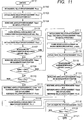
9 illustriert einen Ablauf der Absolutpositionsbestimmung in dieser Ausführungsform. 9 illustrates a sequence of the absolute position determination in this embodiment.
Der Absolutpositionswert wird durch den ABS-Bestimmer 101 bestimmt.The absolute position value is determined by the ABS determiner 101 certainly.
In Schritt S901 fängt die Verarbeitung an und fährt dann mit Schritt S902 fort.In step S901 starts processing and then moves at step S902 away.
In Schritt S902 wird ein Relativpositionswert Pincc initialisiert, und die Verarbeitung fährt mit Schritt S903 fort. Im Folgenden wird die Absolutposition in Schritt S902 als Anfangsposition einer Relativposition definiert, und der Relativpositionswert Pincc wird als Relativposition-Versatzbetrag zur Anfangsposition aktualisiert. Die Verarbeitung fährt mit Schritt S903 fort.In step S902 a relative position value Pincc is initialized, and processing goes to step S903 away. The following is the absolute position in step S902 is defined as the initial position of a relative position, and the relative position value Pincc is updated as the relative position offset amount to the initial position. The processing moves with step S903 away.
In Schritt S903 wird der gegenwärtige Relativpositionswert Pincc als Relativpositionswert Pinc1 an einer gegenwärtigen Position (Position 1) festgehalten, und die Verarbeitung fährt mit Schritt S904 fort.In step S903 the current relative position value Pincc is fixed as the relative position value Pinc1 at a current position (position 1), and the processing goes to step S904 away.
In Schritt S904 wird der Absolutpositionswert Pabs an der gegenwärtigen Position (Position 1) berechnet, und der berechnete Absolutpositionswert Pabs wird als Absolutpositionswert Pabs1 festgehalten. Dann fährt die Verarbeitung mit Schritt S905 fort.In step S904 the absolute position value Pabs at the current position (position 1) is calculated, and the calculated absolute position value Pabs is held as the absolute position value Pabs1. Then the processing moves with step S905 away.
In Schritt S905 wird der Relativpositionswert Pincc an der gegenwärtigen Position aktualisiert, und die Verarbeitung fährt mit Schritt S906 fort.In step S905 the relative position value Pincc is updated at the current position, and processing goes to step S906 away.
Wenn in Schritt S906 basierend auf dem aktualisierten Relativpositionswert Pincc bestimmt wird, dass das bewegliche Element sich von der Position 1 oder einer Absolutpositionswert-Pabsc-Berechnungsposition (später beschrieben) nicht um einen vorbestimmten Bewegungsumfang Mpb bewegt hat, kehrt die Verarbeitung zu Schritt S905 zurück, und andernfalls fährt die Verarbeitung mit Schritt S907 fort. In diesem Fall ist der vorbestimmte Bewegungsumfang Mpb irgendein Wert, der kleiner oder gleich zum Minimalbewegungsumfang Lmsmin ist.If in step S906 it is determined based on the updated relative position value Pincc that the movable member has not moved a predetermined amount of movement Mpb from position 1 or an absolute position value Pabsc calculation position (described later), the processing returns to step S905 otherwise, processing continues with step S907 away. In this case, the predetermined amount of movement Mpb is any value less than or equal to the minimum amount of movement Lmsmin.
In Schritt S907 wird der Absolutpositionswert Pabs an der gegenwärtigen Position berechnet, und der berechnete Absolutpositionswert Pabs wird als Absolutpositionswert Pabsc' festgehalten. Dann fährt die Verarbeitung mit Schritt S908 fort.In step S907 the absolute position value Pabs at the present position is calculated, and the calculated absolute position value Pabs is held as the absolute position value Pabsc '. Then the processing moves with step S908 away.
Wenn in Schritt S908 die Differenz zwischen dem Absolutpositionswert Pabsc' an der gegenwärtigen Position und dem Absolutpositionswert Pabs1 an der Position 1 zur Differenz zwischen dem Relativpositionswert Pincc an der gegenwärtigen Position und dem Relativpositionswert Pinc1 an der Position 1 passt, fährt die Verarbeitung mit Schritt S909 fort, und andernfalls fährt die Verarbeitung mit Schritt S911 fort.If in step S908 the difference between the absolute position value Pabsc 'at the current position and the absolute position value Pabs1 at the position 1 matches the difference between the relative position value Pincc at the current position and the relative position value Pinc1 at the position 1, processing goes to step S909 otherwise processing continues with step S911 away.
In diesem Fall, wenn die Differenz zwischen den Absolutpositionswerten nicht zur Differenz zwischen den Relativpositionswerten passt, kann man bestimmen, dass ein Fehler in der Berechnung des Absolutpositionswerts an irgendeiner aus der gegenwärtigen Position und der Position 1 aufgetreten ist. Das heißt man kann bestimmen, dass der Fremdkörper 802 irgendwo im Rasterlesegebiet 801 an der gegenwärtigen Position oder im Rasterlesegebiet 801 an der Position 1 liegt.In this case, when the difference between the absolute position values does not match the difference between the relative position values, it can be determined that an error has occurred in the calculation of the absolute position value at any one of the current position and position 1. That means you can determine that the foreign body 802 somewhere in the raster reading area 801 at the current location or in the raster reading area 801 is at position 1.
In Schritt S909 wird basierend auf dem Relativpositionswert Pincc bestimmt, ob die gegenwärtige Position sich von der Position 1 um den Minimalbewegungsumfang Lmsmin oder mehr bewegt hat oder nicht. Wenn die gegenwärtige Position sich um den Minimalbewegungsumfang Lmsmin oder mehr bewegt hat, fährt die Verarbeitung mit Schritt S910 fort. Wenn die gegenwärtige Position sich nicht um den Minimalbewegungsumfang Lmsmin oder mehr bewegt hat, kehrt die Verarbeitung zu Schritt S905 zurück.In step S909 it is determined based on the relative position value Pincc whether the current position is different from the position 1 has moved or not by the minimum amount of movement Lmsmin or more. When the current position has moved the minimum amount of movement Lmsmin or more, processing goes to step S910 away. If the current position has not moved the minimum amount of movement Lmsmin or more, processing returns to step S905 back.
In Schritt S910 wird der Absolutpositionswert Pabsc' als Referenz-Absolutpositionswert Pabsb bestimmt, weil kein Fehler im Absolutpositionswert Pabs detektiert worden ist, selbst wenn die gegenwärtige Position sich um den Minimalbewegungsumfang Lmsmin oder mehr bewegt hat. Weiterhin wird der gegenwärtige Relativpositionswert Pincc als Referenz-Relativpositionswert Pincb festgehalten, und die Verarbeitung fährt mit Schritt S916 fort und endet.In step S910 the absolute position value Pabsc 'is determined as the reference absolute position value Pabsb because no error has been detected in the absolute position value Pabs even if the current position is around Has moved the minimum amount of movement Lmsmin or more. Furthermore, the current relative position value Pincc is held as the reference relative position value Pincb, and the processing goes to step S916 away and ends.
Im vom Schritt S908 abzweigenden Schritt S911 wird der Relativpositionswert Pincc an der gegenwärtigen Position als Relativpositionswert Pinc2 an der Position 2 festgehalten. Weiterhin wird der Absolutpositionswert Pabsc' an der gegenwärtigen Position als Absolutpositionswert Pabs2 an der Position 2 festgehalten, und die Verarbeitung fährt mit Schritt S912 fort.Im off the step S908 branching step S911 the relative position value Pincc at the current position is fixed as the relative position value Pinc2 at position 2. Furthermore, the absolute position value Pabsc 'at the present position is fixed as the absolute position value Pabs2 at position 2, and the processing goes to step 2 S912 away.
In Schritt S912 wird der Relativpositionswert Pincc an der gegenwärtigen Position aktualisiert, und die Verarbeitung fährt mit Schritt S913 fort.In step S912 the relative position value Pincc is updated at the current position, and processing goes to step S913 away.
In Schritt S913 fährt die Verarbeitung mit Schritt S914 fort, wenn die Differenz zwischen dem Relativpositionswert Pincc und dem Relativpositionswert Pinc1 größer oder gleich zum Minimalbewegungsumfang Lmsmin ist und die Differenz zwischen dem Relativpositionswert Pincc und dem Relativpositionswert Pinc2 größer oder gleich zum Minimalbewegungsumfang Lmsmin ist. Wenn die Differenz zwischen dem Relativpositionswert Pincc und dem Relativpositionswert Pinc1 größer oder gleich zum Minimalbewegungsumfang Lmsmin ist und die Differenz zwischen dem Relativpositionswert Pincc und dem Relativpositionswert Pinc2 nicht größer oder gleich zum Minimalbewegungsumfang Lmsmin ist, kehrt die Verarbeitung zu Schritt S912 zurück.In step S913 the processing moves with step S914 continues when the difference between the relative position value Pincc and the relative position value Pinc1 is greater than or equal to the minimum amount of movement Lmsmin and the difference between the relative position value Pincc and the relative position value Pinc2 is greater than or equal to the minimum amount of movement Lmsmin. When the difference between the relative position value Pincc and the relative position value Pinc1 is greater than or equal to the minimum movement amount Lmsmin and the difference between the relative position value Pincc and the relative position value Pinc2 is not greater than or equal to the minimum movement amount Lmsmin, the processing returns to step S912 back.
In Schritt S914 wird der Absolutpositionswert Pabs an der gegenwärtigen Position berechnet, und der berechnete Absolutpositionswert Pabs wird als der Absolutpositionswert Pabsc' festgehalten. Dann fährt die Verarbeitung mit Schritt S915 fort.In step S914 the absolute position value Pabs at the current position is calculated, and the calculated absolute position value Pabs is held as the absolute position value Pabsc '. Then the processing moves with step S915 away.
In Schritt S915 wird bestimmt, dass die gegenwärtige Position sich von der Fehlerauftrittsposition um den Minimalbewegungsumfang Lmsmin oder mehr bewegt hat und basierend auf dem Rasterlesegebiet 801 nicht durch den Fremdkörper 802 beeinflusst ist, und der Absolutpositionswert Pabsc' wird als der Referenz-Absolutpositionswert Pabsb bestimmt. Dann fährt die Verarbeitung mit Schritt S916 fort.In step S915 it is determined that the current position has moved from the error occurrence position by the minimum amount of movement Lmsmin or more and based on the raster reading area 801 not through the foreign body 802 is influenced, and the absolute position value Pabsc 'is determined as the reference absolute position value Pabsb. Then the processing moves with step S916 away.
Wenn die Verarbeitung mit Schritt S916 fortfährt, endet die Verarbeitung.When processing with step S916 continues, processing ends.
Danach wird der gegenwärtige Absolutpositionswert Pabsc basierend auf dem Referenz-Absolutpositionswert Pabsb, dem Referenz-Relativpositionswert Pincb, und dem gegenwärtigen Relativpositionswert Pincc bestimmt. Der gegenwärtige Absolutpositionswert Pabsc wird durch Ausdruck (21) ausgedrückt.Thereafter, the current absolute position value Pabsc is determined based on the reference absolute position value Pabsb, the reference relative position value Pincb, and the current relative position value Pincc. The current absolute position value Pabsc is expressed by expression (21).
In der Positionsdetektiervorrichtung dieser Ausführungsform wird, wenn das bewegliche Element durch irgendeine Operation unmittelbar nach dem Einschalten der Vorrichtung um einen geringen Betrag bewegt wird, eine Absolutposition zu diesem Zeitpunkt natürlich bestimmt.In the position detecting device of this embodiment, when the movable member is moved a small amount by any operation immediately after the device is turned on, an absolute position at that time is naturally determined.
In dieser Ausführungsform wird, falls der Absolutpositionswert nicht zum Relativpositionswert passt, der Absolutpositionswert Pabs an der um den Minimalbewegungsumfang Lmsmin oder mehr bewegten Absolutposition als der Referenz-Absolutpositionswert Pabsb bestimmt.In this embodiment, if the absolute position value does not match the relative position value, the absolute position value Pabs at the absolute position moved by the minimum amount of movement Lmsmin or more is determined as the reference absolute position value Pabsb.
Jedoch kann ein anderes Verfahren benutzt werden. Das heißt die Diskrepanz zwischen dem Absolutpositionswert und dem Relativpositionswert wird wieder geprüft, und wenn die Diskrepanz auftritt, wird der Referenz-Absolutpositionswert Pabsb nicht bestimmt, bis der Absolutpositionswert und der Relativpositionswert zueinander passen.However, another method can be used. That is, the discrepancy between the absolute position value and the relative position value is checked again, and when the discrepancy occurs, the reference absolute position value Pabsb is not determined until the absolute position value and the relative position value match.
Weiterhin kann auch das Folgende durchgeführt werden. An mehreren um den Minimalbewegungsumfang Lmsmin oder mehr auseinander liegenden Absolutpositionen werden die Absolutpositionswerte und die Relativpositionswerte aufgezeichnet, und der Referenz-Absolutpositionswert kann basierend auf dem Absolutpositionswert bestimmt werden, an dem das Zueinanderpassen basierend auf der Beziehung zwischen den Absolutpositionswerten und den Relativpositionswerten an den mehreren Absolutpositionen oft auftritt.Furthermore, the following can also be performed. The absolute position values and the relative position values are recorded at a plurality of absolute positions spaced apart by the minimum movement amount Lmsmin or more, and the reference absolute position value can be determined based on the absolute position value at which the match is based on the relationship between the absolute position values and the relative position values at the plurality of absolute positions occurs often.
Dementsprechend kann, selbst falls Staubpartikel und Kratzer auf der Skala im Absolutwertgeber des Noniustyps vorhanden sind, eine Absolutposition mit hoher Zuverlässigkeit berechnet werden, während fehlerhafte Absolutpositionsberechnung verhindert wird.Accordingly, even if there are dust particles and scratches on the scale in the vernier type absolute encoder, an absolute position can be calculated with high reliability while preventing erroneous absolute position calculation.
Weiterhin ist in dieser Ausführungsform ein optischer Wertgeber beschrieben worden. Jedoch ist die vorliegende Erfindung nicht darauf beschränkt, und selbst in einem magnetischen oder elektrostatischen Absolutwertgeber können ähnliche Wirkungen ausgeübt werden auf was von außen Detektion von einem periodischen Signal stört aufgrund von Defekten oder dergleichen auf der Skala, in der ein periodisches Raster in der Bewegungsrichtung ausgebildet ist.Furthermore, an optical value transmitter has been described in this embodiment. However, the present invention is not limited to this, and even in a magnetic or electrostatic absolute encoder, similar effects can be exerted on what interferes with outside detection of a periodic signal due to defects or the like on the scale in which a periodic grid is formed in the moving direction is.
Zweite AusführungsformSecond embodiment
Als nächstes wird eine zweite Ausführungsform der vorliegenden Erfindung unter Bezugnahme auf 10 beschrieben.Next, a second embodiment of the present invention will be described with reference to FIG 10 described.
10 ist ein Anordnungsblockdiagramm dieser Ausführungsform, und dieselbe Anordnung wie die von 1 ist mit denselben Bezugszeichen bezeichnet. 10 FIG. 13 is an arrangement block diagram of this embodiment, and the same arrangement as that of FIG 1 is denoted by the same reference numerals.
Ein ABS-Bestimmer 1001 ist ein Absolutposition-Bestimmer zum Bestimmen der gegenwärtigen Absolutposition Pabsc basierend auf dem durch den ABS/INC-Rechner 102 berechneten Absolutpositionswert Pabs und Relativpositionswert Pinc, und unterscheidet sich in seiner Operation vom in der ersten Ausführungsform beschriebenen ABS-Bestimmer 101. Eine Antriebssteuerung 1002 ist konfiguriert, ein bewegliches Element 1004 anzutreiben und zu steuern. Ein Motor 1003 ist konfiguriert, das bewegliche Element 1004 anzutreiben, und Beispiele davon beinhalten einen Gleichstrommotor und einen Schrittmotor. Das bewegliche Element 1004 wird Absolutpositionsdetektion durch den ABS-Sensor 104 unterzogen.An ABS determiner 1001 is an absolute position determiner for determining the current absolute position Pabsc based on that by the ABS / INC calculator 102 calculated absolute position value Pabs and relative position value Pinc, and is different in operation from the ABS determiner described in the first embodiment 101 . A drive control 1002 is configured to be a movable element 1004 to drive and control. One engine 1003 is configured, the movable element 1004 and examples thereof include a DC motor and a stepping motor. The moving element 1004 becomes absolute position detection by the ABS sensor 104 subjected.
Als nächstes wird die Operation dieser Ausführungsform beschrieben.Next, the operation of this embodiment will be described.
11 illustriert einen Ablauf der Absolutpositionsbestimmung in dieser Ausführungsform. 11 illustrates a sequence of the absolute position determination in this embodiment.
Der Absolutpositionswert wird durch den ABS-Bestimmer 1001 bestimmt.The absolute position value is determined by the ABS determiner 1001 certainly.
In Schritt S1101 fängt die Verarbeitung an und fährt dann mit Schritt S1102 fort.In step S1101 starts processing and then moves at step S1102 away.
In Schritt S1102 wird der Relativpositionswert Pincc initialisiert, und die Verarbeitung fährt mit Schritt S1103 fort. Im Folgenden wird die Absolutposition in Schritt S1102 als Anfangsposition einer Relativposition definiert, und der Relativpositionswert Pincc wird als Relativposition-Versatzbetrag von der Anfangsposition aus aktualisiert.In step S1102 the relative position value Pincc is initialized, and processing proceeds to step S1103 away. The following is the absolute position in step S1102 is defined as the initial position of a relative position, and the relative position value Pincc is updated as the relative position offset amount from the initial position.
In Schritt S1103 wird der gegenwärtige Relativpositionswert Pincc als der Relativpositionswert Pinc1 an der gegenwärtigen Position (Position 1) festgehalten, und die Verarbeitung fährt mit Schritt S1104 fort.In step S1103 the current relative position value Pincc is fixed as the relative position value Pinc1 at the current position (position 1), and the processing goes to step S1104 away.
In Schritt S1104 wird der Absolutpositionswert Pabs an der gegenwärtigen Position (Position 1) berechnet. Der berechnete Absolutpositionswert Pabs wird als der Absolutpositionswert Pabs 1 festgehalten, und die Verarbeitung fährt mit Schritt S1105 fort.In step S1104 the absolute position value Pabs at the current position (position 1) is calculated. The calculated absolute position value Pabs is held as the absolute position value Pabs 1, and the processing goes to step S1105 away.
In Schritt S1105 weist der ABS-Bestimmer 1001 die Antriebssteuerung 1002 an das bewegliche Element 1004 um einen vorbestimmten Bewegungsumfang Mpb zu fahren, und die Verarbeitung fährt mit Schritt S1106 fort. In diesem Fall ist der vorbestimmte Bewegungsumfang Mpb irgendein Wert, der kleiner oder gleich zum Minimalbewegungsumfang Lmsmin ist. Die Antriebssteuerung 1002 steuert den Motor 1003 gemäß der Anweisung und treibt das bewegliche Element 1004 an. Der ABS-Sensor 104 gibt ein zur Position des beweglichen Elements entsprechendes Signal 1004 an den AD-Wandler 105 gemäß dem Antrieb vom beweglichen Element 1004 aus.In step S1105 instructs the ABS determiner 1001 the drive control 1002 to the moving element 1004 to travel a predetermined amount of movement Mpb, and the processing goes to step S1106 away. In this case, the predetermined amount of movement Mpb is any value less than or equal to the minimum amount of movement Lmsmin. The drive control 1002 controls the engine 1003 according to the instruction and drives the movable element 1004 at. The ABS sensor 104 gives a signal corresponding to the position of the movable element 1004 to the AD converter 105 according to the drive from the moving element 1004 out.
In Schritt S1106 wird der Relativpositionswert Pincc an der gegenwärtigen Position aktualisiert, und die Verarbeitung fährt mit Schritt S1107 fort.In step S1106 the relative position value Pincc is updated at the current position, and processing goes to step S1107 away.
Wenn in Schritt S1107 basierend auf dem aktualisierten Relativpositionswert Pincc bestimmt wird, dass das bewegliche Element sich von der Position 1 oder einer Absolutpositionswert-Pabsc-Berechnungsposition (später beschrieben) nicht um den vorbestimmten Bewegungsumfang Mpb bewegt hat, kehrt die Verarbeitung zu Schritt S1106 zurück, und andernfalls fährt die Verarbeitung mit Schritt S1108 fort.If in step S1107 based on the updated relative position value Pincc, it is determined that the movable member is deviated from the position 1 or an absolute position value Pabsc calculation position (described later) has not moved the predetermined amount of movement Mpb, the processing returns to step S1106 otherwise, processing continues with step S1108 away.
In Schritt S1108 wird der Absolutpositionswert Pabs an der gegenwärtigen Position berechnet. Der berechnete Absolutpositionswert Pabs wird als der Absolutpositionswert Pabsc' festgehalten. Dann fährt die Verarbeitung mit Schritt S1109 fort.In step S1108 the absolute position value Pabs at the current position is calculated. The calculated absolute position value Pabs is held as the absolute position value Pabsc '. Then the processing moves with step S1109 away.
Wenn in Schritt S1109 die Differenz zwischen dem Absolutpositionswert Pabsc' an der gegenwärtigen Position und dem Absolutpositionswert Pabs1 an der Position 1 zur Differenz zwischen dem Relativpositionswert Pincc an der gegenwärtigen Position und dem Relativpositionswert Pinc1 an der Position 1 passt, fährt die Verarbeitung mit Schritt S1110 fort, und andernfalls fährt die Verarbeitung mit Schritt S1112 fort.If in step S1109 the difference between the absolute position value Pabsc 'at the current position and the absolute position value Pabs1 at the position 1 matches the difference between the relative position value Pincc at the current position and the relative position value Pinc1 at the position 1, processing goes to step S1110 otherwise processing continues with step S1112 away.
In Schritt S1110 wird basierend auf dem Relativpositionswert Pincc bestimmt, ob die gegenwärtige Position sich von der Position 1 aus um den Minimalbewegungsumfang Lmsmin oder mehr bewegt hat oder nicht. Wenn die gegenwärtige Position sich um den Minimalbewegungsumfang Lmsmin oder mehr bewegt hat, fährt die Verarbeitung mit Schritt S1111 fort. Wenn die gegenwärtige Position sich nicht um den Minimalbewegungsumfang Lmsmin oder mehr bewegt hat, kehrt die Verarbeitung zu Schritt S1105 ' zurück.In step S1110 it is determined based on the relative position value Pincc whether or not the current position has moved from position 1 by the minimum amount of movement Lmsmin or more. When the current position has moved the minimum amount of movement Lmsmin or more, processing goes to step S1111 away. If the current position has not moved the minimum amount of movement Lmsmin or more, processing returns to step S1105 ' back.
In Schritt S1111 wird der Absolutpositionswert Pabsc' als der Referenz-Absolutpositionswert Pabsb bestimmt, weil kein Fehler im Absolutpositionswert Pabs detektiert worden ist, selbst wenn die gegenwärtige Position sich um den Minimalbewegungsumfang Lmsmin oder mehr bewegt hat. Weiterhin wird der gegenwärtige Relativpositionswert Pincc als der Referenz-Relativpositionswert Pincb festgehalten, und die Verarbeitung fährt mit Schritt S1118 fort.In step S1111 the absolute position value Pabsc 'is determined as the reference absolute position value Pabsb because no error has been detected in the absolute position value Pabs even if the current position has moved the minimum amount of movement Lmsmin or more. Furthermore, the current relative position value Pincc is held as the reference relative position value Pincb, and the processing goes to step S1118 away.
In Schritt S1112 wird der Relativpositionswert Pincc an der gegenwärtigen Position als der Relativpositionswert Pinc2 an der Position 2 festgehalten. Weiterhin wird der Absolutpositionswert Pabsc' an der gegenwärtigen Position als der Absolutpositionswert Pabs2 an der Position 2 festgehalten, und die Verarbeitung fährt mit Schritt S1113 fort.In step S1112 becomes the relative position value Pincc at the current position as the relative position value Pinc2 at the position 2 held. Furthermore, the absolute position value Pabsc 'at the current position becomes the absolute position value Pabs2 at the position 2 held, and processing moves at pace S1113 away.
In Schritt S1113 weist der ABS-Bestimmer 1001 die Antriebssteuerung 1002 an das bewegliche Element 1004 um den Minimalbewegungsumfang Lmsmin zu fahren, und die Verarbeitung fährt mit Schritt S1114 fort.In step S1113 instructs the ABS determiner 1001 the drive control 1002 to the moving element 1004 to move the minimum amount of movement Lmsmin, and the processing moves to step S1114 away.
In Schritt S1114 wird der Relativpositionswert Pincc an der gegenwärtigen Position aktualisiert, und die Verarbeitung fährt mit Schritt S1115 fort.In step S1114 the relative position value Pincc is updated at the current position, and processing goes to step S1115 away.
Wenn in Schritt S1115 die Differenz zwischen dem Relativpositionswert Pincc und dem Relativpositionswert Pinc1 größer oder gleich zum Minimalbewegungsumfang Lmsmin ist und die Differenz zwischen dem Relativpositionswert Pincc und dem Relativpositionswert Pinc2 größer oder gleich zum Minimalbewegungsumfang Lmsmin ist, fährt die Verarbeitung mit Schritt S1116 fort. Die Differenz zwischen dem Relativpositionswert Pincc und dem Relativpositionswert Pinc1 ist größer oder gleich zum Minimalbewegungsumfang Lmsmin und die Differenz zwischen dem Relativpositionswert Pincc und dem Relativpositionswert Pinc2 ist nicht größer oder gleich zum Minimalbewegungsumfang Lmsmin, die Verarbeitung kehrt zu Schritt S1114 zurück.If in step S1115 the difference between the relative position value Pincc and the relative position value Pinc1 is greater than or equal to the minimum amount of movement Lmsmin and the difference between the relative position value Pincc and the relative position value Pinc2 is greater than or equal to the minimum amount of movement Lmsmin, the processing continues with step S1116 away. The difference between the relative position value Pincc and the relative position value Pinc1 is greater than or equal to the minimum amount of movement Lmsmin, and the difference between the relative position value Pincc and the relative position value Pinc2 is not greater than or equal to the minimum amount of movement Lmsmin, the processing returns to step S1114 back.
In Schritt S1116 wird der Absolutpositionswert Pabs an der gegenwärtigen Position berechnet. Der berechnete Absolutpositionswert Pabs wird als der Absolutpositionswert Pabsc' festgehalten. Dann fährt die Verarbeitung mit Schritt S1117 fort.In step S1116 the absolute position value Pabs at the current position is calculated. The calculated absolute position value Pabs is held as the absolute position value Pabsc '. Then the processing moves with step S1117 away.
In Schritt S1117 wird bestimmt, dass die gegenwärtige Position sich von der Fehlerauftrittsposition um den Minimalbewegungsumfang Lmsmin oder mehr bewegt hat und basierend auf dem Rasterlesegebiet 801 nicht durch den Fremdkörper 802 beeinflusst ist, und der Absolutpositionswert Pabsc' wird als der Referenz-Absolutpositionswert Pabsb bestimmt. Dann fährt die Verarbeitung mit Schritt S1118 fort.In step S1117 it is determined that the current position has moved from the error occurrence position by the minimum amount of movement Lmsmin or more and based on the raster reading area 801 not through the foreign body 802 is influenced, and the absolute position value Pabsc 'is determined as the reference absolute position value Pabsb. Then the processing moves with step S1118 away.
In Schritt S1118 weist der ABS-Bestimmer 1001 die Antriebssteuerung 1002 an das bewegliche Element 1004 zum Relativpositionswert Pinc1 zu fahren, der die Anfangsposition ist, und die Verarbeitung fährt mit Schritt S11 19 fort.In step S1118 instructs the ABS determiner 1001 the drive control 1002 to the moving element 1004 to move to the relative position value Pinc1 which is the initial position, and the processing moves to step S11 19 away.
In Schritt S1119 wird der Relativpositionswert Pincc an der gegenwärtigen Position aktualisiert, und die Verarbeitung fährt mit Schritt S1120 fort.In step S1119 the relative position value Pincc is updated at the current position, and processing goes to step S1120 away.
Wenn in Schritt S1120 der Relativpositionswert Pincc zum Relativpositionswert Pinc1 passt, fährt die Verarbeitung mit Schritt S1121 fort und endet. Wenn der Relativpositionswert Pincc nicht zum Relativpositionswert Pinc1 passt, kehrt die Verarbeitung zu Schritt S1119 zurück.If in step S1120 the relative position value Pincc matches the relative position value Pinc1, processing continues with step S1121 away and ends. When the relative position value Pincc does not match the relative position value Pinc1, processing returns to step S1119 back.
Danach wird durch dasselbe Verfahren wie das der ersten Ausführungsform der gegenwärtige Absolutpositionswert Pabsc basierend auf dem Referenz-Absolutpositionswert Pabsb, dem Referenz-Relativpositionswert Pincb, und dem gegenwärtigen Relativpositionswert Pincc bestimmt.Thereafter, by the same method as that of the first embodiment, the current absolute position value Pabsc is determined based on the reference absolute position value Pabsb, the reference relative position value Pincb, and the current relative position value Pincc.
Im oben-erwähnten Verarbeitungsablauf wird die Absolutposition beim Fortschreiten zu Schritt S1118 bestimmt. In dieser Ausführungsform wird das bewegliche Element 1004 zwangsweise bewegt, um die Absolutposition zu bestimmen, und folglich ist die Verarbeitung von Schritt S1118 bis Schritt S1120 die Verarbeitung zum Zurückkehren zum Zustand vor Beginn des Verarbeitungsablaufs. Für den oben-erwähnten Zweck kann eine Einheit zum Speichern des Relativpositionswerts unmittelbar nach Anfang des Verarbeitungsablaufs von 11 bereitgestellt werden. In dieser Ausführungsform wird, falls der Absolutpositionswert nicht zum Relativpositionswert passt, der Absolutpositionswert Pabs an der um den Minimalbewegungsumfang Lmsmin oder mehr bewegten Absolutposition als der Referenz-Absolutpositionswert Pabsb bestimmt.In the above-mentioned processing, the absolute position becomes step as it proceeds S1118 certainly. In this embodiment, the movable element 1004 forcibly moved to determine the absolute position and hence the processing of step S1118 up step S1120 the processing to return to the state before the start of the processing flow. For the above-mentioned purpose, a unit for storing the relative position value can be provided immediately after the processing sequence of 11 to be provided. In this embodiment, if the absolute position value does not match the relative position value, the absolute position value Pabs at the absolute position moved by the minimum amount of movement Lmsmin or more is determined as the reference absolute position value Pabsb.
Jedoch kann ein anderes Verfahren benutzt werden. Das heißt die Diskrepanz zwischen dem Absolutpositionswert und dem Relativpositionswert wird wieder geprüft, und, wenn die Diskrepanz auftritt, wird das bewegliche Element 1004 wieder um den Minimalbewegungsumfang Lmsmin oder mehr gefahren, und die Referenz-Absolutposition Pabsb wird nicht bestimmt, bis der Absolutpositionswert und der Relativpositionswert zueinander passen.However, another method can be used. That is, the discrepancy between the absolute position value and the relative position value is checked again, and if the discrepancy occurs, the movable element becomes 1004 moved again by the minimum amount of movement Lmsmin or more, and the reference absolute position Pabsb is not determined until the absolute position value and the relative position value match one another.
Weiterhin kann auch das Folgende durchgeführt werden. Das bewegliche Element 1004 wird zu mehreren Positionen gefahren, die um den Minimalbewegungsumfang Lmsmin oder mehr auseinander liegen, und an jeder Position werden der Absolutpositionswert und der Relativpositionswert berechnet. Danach kann man einen Referenz-Absolutpositionswert basierend auf dem Absolutpositionswert bestimmen, an dem das Zueinanderpassen basierend auf der Beziehung zwischen den Absolutpositionswerten und den Relativpositionswerten an den mehreren Absolutpositionen oft auftritt.Furthermore, the following can also be performed. The moving element 1004 is moved to a plurality of positions that are apart by the minimum amount of movement Lmsmin or more, and the absolute position value and the relative position value are calculated at each position. Thereafter, it is possible to determine a reference absolute position value based on the absolute position value at which the matching often occurs based on the relationship between the absolute position values and the relative position values at the plural absolute positions.
Dementsprechend kann, selbst falls Staubpartikel und Kratzer auf der Skala im Absolutwertgeber des Noniustyps vorhanden sind, eine Absolutposition mit hoher Zuverlässigkeit berechnet werden, während fehlerhafte Absolutpositionsberechnung durch das minimale Fahren zum Zeitpunkt des anfänglichen Einschaltens verhindert wird.Accordingly, even if there are dust particles and scratches on the scale in the vernier type absolute encoder, an absolute position can be calculated with high reliability while preventing erroneous absolute position calculation by the minimum travel at the time of initial power-up.
Weiterhin ist in der oben-erwähnten Ausführungsform die Benutzung eines optischen Wertgebers erläutert worden. Jedoch ist die vorliegende Erfindung nicht darauf beschränkt, und ein magnetischer oder elektrostatischer Absolutwertgeber kann benutzt werden.Furthermore, in the above-mentioned embodiment, the use of an optical encoder has been explained. However, the present invention is not limited to this, and a magnetic or electrostatic absolute encoder can be used.
Eine Linsenvorrichtung, die die Wirkung der vorliegenden Erfindung darzubieten vermag, kann verwirklicht werden durch Anwenden der Positionsdetektiervorrichtung der Ausführungsformen an einer ein bewegliches optisches Element beinhaltenden Linsenvorrichtung, um die Position des beweglichen optischen Elements zu detektieren. Weiterhin kann eine Bildaufnahmevorrichtung, die die Wirkung der vorliegenden Erfindung darzubieten vermag, verwirklicht werden durch Anwenden der Positionsdetektiervorrichtung der Ausführungsformen an einer Bildaufnahmevorrichtung, die eine ein bewegliches optisches Element beinhaltende Linsenvorrichtung und eine Kameravorrichtung beinhaltet, um die Position des beweglichen optischen Elements zu detektieren.A lens device capable of exhibiting the effect of the present invention can be realized by applying the position detecting device of the embodiments to a lens device including a movable optical element to detect the position of the movable optical element. Furthermore, an image pickup device capable of exhibiting the effect of the present invention can be realized by applying the position detecting device of the embodiments to an image pickup device including a lens device including a movable optical element and a camera device to detect the position of the movable optical element.
Andere AusführungsformenOther embodiments
Ausführungsform(en) der vorliegenden Erfindung können auch durch einen Computer eines Systems oder Vorrichtung realisiert werden, der auf einem Speichermedium (das vollständiger auch als ein ‚nicht-flüchtiges computerlesbares Speichermedium‘ bezeichnet werden kann) aufgezeichnete computerausführbare Anweisungen (z.B. ein oder mehr Programme) ausliest und ausführt, um die Funktionen von einer oder mehr der oben beschriebenen Ausführungsform(en) durchzuführen, und/oder der ein oder mehr Schaltungen (z.B. eine anwenderspezifisch-integrierte Schaltung (ASIC)) beinhaltet zum Durchführen der Funktionen von einer oder mehr der oben beschriebenen Ausführungsform(en), sowie durch ein durch den Computer des Systems oder Vorrichtung durchgeführtes Verfahren durch, zum Beispiel, Auslesen und Ausführen der computerausführbaren Anweisungen von dem Speichermedium, um die Funktionen von einer oder mehr der oben beschriebenen Ausführungsform(en) durchzuführen, und/oder Steuern der ein oder mehr Schaltungen, um die Funktionen von einer oder mehr der oben beschriebenen Ausführungsform(en) durchzuführen. Der Computer kann einen oder mehr Prozessoren (z.B. eine zentrale Verarbeitungseinheit (CPU), eine Mikroprozessoreinheit (MPU)) umfassen, und kann ein Netzwerk von separaten Computern oder separaten Computerprozessoren enthalten, um die computerausführbaren Anweisungen auszulesen und auszuführen. Die computerausführbaren Anweisungen können dem Computer zum Beispiel von einem Netzwerk oder dem Speichermedium zur Verfügung gestellt werden. Das Speichermedium kann zum Beispiel eins oder mehr aus einer Festplatte, einem Speicher mit wahlfreiem Zugriff (RAM), einem Nur-Lese-Speicher (ROM), einem Speicher von verteilten Computersystemen, einer optischen Platte (wie etwa eine Compact Disc (CD), Digital Versatile Disc (DVD) oder Blu-ray Disc (BD)™), einer Flashspeichervorrichtung, einer Speicherkarte, und dergleichen enthalten.Embodiment (s) of the present invention can also be implemented by a computer of a system or apparatus that can store computer-executable instructions (e.g., one or more programs) recorded on a storage medium (which may also be more fully referred to as a 'non-transitory computer-readable storage medium'). reads and executes to perform the functions of one or more of the embodiment (s) described above and / or which includes one or more circuits (e.g., an application-specific integrated circuit (ASIC)) to perform the functions of one or more of the above described embodiment (s), as well as by a method performed by the computer of the system or apparatus by, for example, reading and executing the computer-executable instructions from the storage medium to perform the functions of one or more of the embodiment (s) described above, and / or controlling one or more switching units to perform the functions of one or more of the embodiment (s) described above. The computer may include one or more processors (e.g., a central processing unit (CPU), a microprocessor unit (MPU)) and may include a network of separate computers or separate computer processors to read and execute the computer-executable instructions. The computer-executable instructions can be made available to the computer from a network or the storage medium, for example. The storage medium may, for example, be one or more of a hard disk, random access memory (RAM), read-only memory (ROM), distributed computer system memory, optical disk (such as a compact disc (CD), Digital Versatile Disc (DVD) or Blu-ray Disc (BD) ™), a flash memory device, a memory card, and the like.
Obwohl die vorliegende Erfindung unter Bezugnahme auf Ausführungsbeispiele beschrieben worden ist, ist selbstverständlich, dass die Erfindung nicht auf die offenbarten Ausführungsbeispiele begrenzt ist. Dem Umfang der folgenden Ansprüche soll die weitestgehende Interpretation zugestanden werden, sodass alle solchen Modifikationen und äquivalenten Strukturen und Funktionen erfasst sind.Although the present invention has been described with reference to exemplary embodiments, it is to be understood that the invention is not limited to the disclosed exemplary embodiments. The scope of the following claims is to be accorded the widest interpretation so that all such modifications and equivalent structures and functions are covered.