General introduction of the present invention
Consider above-mentioned situation, first purpose of the present invention provides a kind of repairing method for color filter and equipment, and it can easily repair the defective of color filter.
Second purpose of the present invention be, a kind of color filter by above-mentioned repairing method for color filter and equipment reparation is provided, utilize this color filter liquid crystal indicator, have the equipment of liquid crystal indicator.
In order to address the above problem and to achieve the above object, repairing method for color filter of the present invention be characterised in that following processing procedure according to its first aspect.
A kind of repairing method for color filter is provided, be used to repair such as the colour of a color filter element of color filter lose or color anomaly defect part, this color filter is by the shape with a predetermined pattern, some is set through forming with predetermined colored painted color-filter element on a transparent substrates; Wherein by utilizing an ink gun that is merely able to discharge different colored coloured materials, will have predetermined colored coloured material and be discharged into the defective part repair-deficiency part of assigning to.
The feature of repairing method for color filter of the present invention also is the following processing procedure according to its second aspect.
A kind of repairing method for color filter is provided, be used for repairing a defect part that the color filter element foreign matter causes such as color filter, this color filter is by the shape with predetermined pattern, some is set through forming with predetermined colored painted color filter element on a transparent substrates; Comprise: first step, remove foreign matter by laser treatment; Second step enters coloured material to repair this color filter element by utilizing an ink gun that is merely able to discharge different colored coloured materials on defect part, this defect part is the part that foreign matter has been removed in first step.
The feature of color filter prosthetic appliance of the present invention is the following setting according to its first aspect.
A kind of color filter prosthetic appliance is provided, in order to repair such as the colour of a color filter element of color filter lose or color anomaly defect part, this color filter is by the shape with a predetermined pattern, some is set through forming with predetermined colored painted color filter element on a transparent substrates.This equipment comprises the pick-up unit that is used to detect defect part; Be used for coloured material is discharged into ink gun on the defect part; Be used for when making color filter relative, keeping the holding device of color filter with pick-up unit and ink gun; The mobile device that is used to make the position of pick-up unit and ink gun to move with respect to the position of holding device; And control device, use so that mobile device will be shifted to one and the corresponding position of ink gun by the detected defect part of pick-up unit, and control, so that ink gun is discharged into coloured material on this defect part.
The feature of color filter prosthetic appliance of the present invention also is the following setting according to its second aspect.
A kind of color filter prosthetic appliance is provided, lose or the defect part of color anomaly in order to repair such as the colour of a color filter element of color filter, this color filter is by the shape with a predetermined pattern, some is set through forming with predetermined colored painted color filter element on a transparent substrates.This equipment comprises: be used for coloured material is discharged into ink gun on the defect part; Be used for when color filter is relative with ink gun, keeping the holding device of color filter; The mobile device that is used for the relative position of mobile ink gun and holding device; And control device, use so that mobile device is shifted to the position of corresponding ink gun with detected defect part, and carry out control, make ink gun that coloured material is discharged on this defect part.
Color filter of the present invention is characterised in that the following setting according to its first aspect.
A kind of color filter is provided, it is by the shape with a predetermined pattern a plurality of warps to be set on a transparent substrates to form with predetermined colored painted color filter element, wherein utilize the coloured material that an ink gun that can discharge different colored coloured materials will a kind of predetermined colour to be discharged into defect part, repair such as the colour loss of color filter element or the defective the color anomaly.
Color filter of the present invention is characterised in that the following setting according to its second aspect.
A kind of color filter is provided, and it is a plurality ofly to form with predetermined colored painted color filter element by being provided with on a transparent substrates with a predetermined pattern; Wherein remove defect part such as the foreign matter in the color filter element by laser treatment; And utilize an ink gun that can discharge different colored coloured materials, and coloured material is discharged on the part of removing defect part, repair this defect part.
Liquid crystal indicator of the present invention is characterised in that the following setting according to its first aspect.
A kind of liquid crystal indicator that utilizes color filter is provided, and this color filter is by the shape with a predetermined pattern a plurality of warps to be set on a transparent substrates to form with predetermined colored painted color filter element; This liquid crystal indicator comprise by repaired such as the colour of color filter element lose or color anomaly the color filter that obtains of defect part, this reparation is by utilizing the ink gun of the coloured material that can discharge different colours, a predetermined colored coloured material being discharged on this defect part finishing; Also comprise a substrate relative with color filter; Wherein a kind of liquid crystal agent material is installed between two substrates.
The feature of liquid crystal indicator of the present invention also is the following setting according to its second aspect.
A kind of liquid crystal indicator that utilizes color filter is provided, and this color filter is that the shape by a predetermined pattern is provided with on a transparent substrates and a plurality ofly forms with predetermined colored painted color filter element; This liquid crystal indicator comprises a color filter, it is to have removed defect part such as the thing of the foreign matter in the color filter element by laser treatment, and utilize the ink gun that can discharge coloured material that need not be colored that a kind of coloured material is discharged into to obtain with the repair-deficiency part on the part of therefrom having removed defect part; Also comprise a substrate relative with color filter; Wherein liquid crystal agent material is encapsulated between two substrates.
Equipment with liquid crystal indicator of the present invention is characterised in that the following setting according to its first aspect.
A kind of liquid crystal indicator that uses color filter is provided, and described color filter is the shape by predetermined pattern, is provided with a plurality ofly to form by the painted color filter element of pre-color on a transparent substrates; It comprises:
One by repair on the described color filter element such as the color filter that color is lost or the unusual such defect part of color obtains, this reparation utilization can be discharged the ink gun of different colored coloured materials and be finished to the predetermined colored coloured material of this defect part discharging; And
A substrate relative with described color filter,
Wherein a kind of liquid crystal agent material is encapsulated between described two substrates.
Equipment with liquid crystal indicator of the present invention is characterised in that the following setting according to its second aspect.
A kind of liquid crystal indicator that uses color filter is provided, and this color filter is the shape by predetermined pattern, is provided with a plurality ofly to form by predetermined colored painted color filter element on a transparent substrates, and it comprises:
Color filter, it be utilize laser treatment removed in the described color filter element such as the such defect part of external foreign matter, and utilize the ink gun can discharge different colored coloured materials on the described part that defective it on has been removed, to discharge coloured material and this defect part is repaired, thereby acquisition; And
A substrate relative with described color filter,
Wherein a kind of liquid crystal agent material is enclosed between described two substrates.
By follow-up description to most preferred embodiment of the present invention, those skilled in the art can also understand other purpose and the advantage outside above discussion the of the present invention.In this manual, description is to carry out in conjunction with the accompanying drawing of a book part as an illustration, and an example of the present invention has been shown in the accompanying drawing.But this example is not a kind of restriction to various embodiments of the invention, therefore, and determining and should carry out the scope of the invention in conjunction with investing instructions claims afterwards.
Description to most preferred embodiment
Figure 1A and 1B are the partial enlarged drawings of having used the color filter of repairing method for color filter of the present invention.
Each color filter 10 is installed on the colour liquid crystal display device that is used for portable personal computer or analog or the front surface of analog.Shown in Figure 1A, the color filter element 10a that redness (R), green (G), blue look (B) arranges two-dimensionally with a matrix form.In the color filter shown in Figure 1A, color filter element 10a arranges with a single matrix form.In the color filter shown in Figure 1B, color filter element 10a arranges with staggered form.The black light shield grid is formed between each color filter element 10a, so that the border between the color filter element 10a becomes clear, so that clearly screen to be provided.
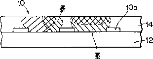
Fig. 2 A is the side cutaway view of color filter 10 among Figure 1A or the 1B.Light shield grid 10b forms on the substrate of glass 12 that constitutes color filter 10 main bodys.Having colored separately color filter element 10a forms on these light shield grid.
When making color filter 10, by sputter with chromium deposition on substrate of glass 12, by photoetching process resulting film is made a matrix figure.This figure is light shield grid 10b.The layer 14 that is colored is formed at these light shield grid 10b.Layer 14 is made up of fiber, acryl resin, gelatin or analog and is absorbed liquid.By the record-header of an ink-jet system, the color filter element that the drop (hereinafter being referred to as " China ink ") that will contain coloured material (dyestuff) is injected in layer 14 forms on the zone.Utilize this processing, layer 14 is carried out painted to form color filter element 10a.
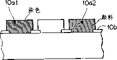
Fig. 2 B utilizes the front to describe the side cutaway view of the color filter 10 of mentioned decoration method of correlation technique part of the present invention or pigment disperse manufactured.In practice, the color filter element of making by decoration method and pigment disperse method is not to be formed in the same substrate.But for convenience of description, in the situation shown in Fig. 2 B, these color filter element are formed in same suprabasil.
Referring to Fig. 2 B, formed element 10a1 by decoration method; That is this color filter element 10a1 obtains by a kind of water soluble polymer material is dyeed.Formed an element 10a2 by pigment disperse method; That is this color filter element 10a2 obtains by dispersed pigments in photosensitive resin.
Note that if desired, on color filter element, should form a protective seam.As this protective seam, for example, the layer that can adopt the resin material of solid by light, thermosetting or light is solid/thermosetting to constitute perhaps can adopt the inoranic membrane that forms by vapour deposition, sputter or similar approach.Also can stand some follow-up processing procedures of position as long as this layer has the transparency after color filter forms, for example ITO (indium tin oxide Indium Tin Oxide) formation is handled and alignment film forms processing, so just can adopt this layer.
In general, color liquid crystal panel can be bonded together by the substrate 54 with a color filter substrate 12 and a counter and encapsulate a kind of liquid crystal agent material 52 between them and form.Some TFT (thin film transistor (TFT)) (not shown) and transparent pixel electrode 53 are formed at matrix form on the inside surface of a substrate 54 of liquid crystal panel.Color filter 10 is arranged on the inside surface of another substrate 12, so that R, G, B coloured material are positioned at the opposite of these pixel capacitors.A transparent counter electrode (public electrode) 50 is formed on the whole surface of color filter 10.Light shield grid 10b generally is formed at color filter substrate 12 1 sides (seeing Figure 12).But in a BM (black matrix) matrix type liquid crystal panel, this grid are formed in (referring to Figure 13) of the TFT base side relative with color filter substrate.Alignment film 51 is formed within the panel of two substrates.Carry out milled processed by collimation film 51, liquid crystal molecule is aimed at a predetermined direction.One polarization plates 55 is affixed on the outside surface of substrate of glass separately.Liquid crystal agent material 52 is filled in the slit (being approximately 2 to 5 μ m) between these substrate of glass.As a kind of back side light, adopt the combination of a fluorescent light (not shown) and a scatter plate usually.By making liquid crystal agent material be used as the optical diaphragm of the optical transmission rate that change launches the back side, carry out display operation.
The situation that wherein above-mentioned liquid crystal panel is applied to information process unit is described below in conjunction with Figure 14 to 16.
Figure 14 is the illustrative arrangement block scheme that the information process unit of above-mentioned liquid crystal panel has been used in expression; This information process unit can be used as a word processor, people's computing machine, a facsimile equipment, a duplicating machine one by one.
Referring to Figure 14, reference number 1801 is represented the control module of a control entire equipment.This control module 1801 comprises a CPU, for example a microprocessor and various I/O mouth, and its control signal by each unit of output/input turnover, data-signal or the like are controlled.Reference number 1802 is represented a display unit, in order on display screen, show various menus, fileinfo and the view data of reading by imaging reader 1807, or the like; Reference number 1803 is represented a transparent pressure sensitive contact type panel that is installed on the display unit 1802.Users etc. press contact type panel 1803 by press...withing one's finger, can project implementation input operations on display unit 1802, the coordinate position input operation, or the like.
Reference number 1804 is represented a FM (frequency modulation) sound source unit, in order to being stored in a memory cell 1810 or the external memory unit 1812 as numerical data by the music information that music editor produced, and from this class storer sense information, thereby finish the FM modulation of information.The sound that loudspeaker unit 1805 will become can listen from the electrical signal conversion of FM sound source unit 1804.Printer unit 1806 is used as the outlet terminal of word processor, personal computer, facsimile equipment and duplicating machine.
Reference number 1807 is represented an imaging reader unit, is used for photoelectricity read purposefully raw data.This imaging reader unit 1807 is arranged on the midway that original text transmits passage, in order to read original text or various other original text in fax and the copying operation.
Transmission/the receiving element of reference number 1808 representative fax (FAX) equipment.The raw data that transmission/receiving element 1808 is read by imaging reader unit 1807 by facsimile transmission, and receive the decode the facsimile signal that is issued.This transmission/receiving element 1808 has the external unit interface function.Reference number 1809 representatives have regular phone function and for example a kind of telephone unit of answering the various telephony features of function.
Reference number 1810 is represented a memory cell, comprises a ROM, in order to storage system program, supervisory routine, application program, font and dictionary.Also comprise a RAM, application program of packing into from external memory storage 1812 in order to storage and fileinfo, a video-ram, or the like.
Reference number 1811 is represented a keyboard unit, in order to input file information and various command.
Reference number 1812 is represented an external memory unit that utilizes floppy disk, hard disk or the like.This external memory unit 1812 be used for storage file information, music and language message, application program of user, or the like.
Figure 15 is the three-dimensional view of information process unit shown in Figure 14.
Referring to Figure 15, reference number 1901 is represented the flat-panel displays of the above-mentioned liquid crystal panel of an employing, its show various menus, curvilinear figure information, fileinfo, or the like, the user presses the surface of contact type panel 1803 by press...withing one's finger, and can carry out coordinate input or project appointment input operation on flat-panel displays 1901.The receiver of reference number 1902 representatives when this equipment is used as a phone.Keyboard removably links to each other with main body through a cable, is used to carry out various file functions and imports various data.Keyboard 1903 has various function keys 1904.Reference number 1905 representatives are inserted floppy disk the insertion port of external memory unit 1812 by it.
Reference number 1906 is represented an original text platen, in order to place the original text that will be read by imaging reader unit 1807 thereon.The rear portion of the original text slave unit of reading unclasps out.In the facsimile reception operation, the data that received are printed by an ink-jet printer 1907.
When above-mentioned information process unit is used as a personal computer or a word processor, various information by keyboard unit 1811 inputs, handled according to preset program by control module 1801, resulting object information is then exported to printer unit 1806 as image.
When information process unit is used as the receiver of facsimile equipment, through the facsimile message of a communication line by 1808 inputs of transmission/receiving element, will in control module 1801, handle according to preset program, and resulting object information is then exported to printer unit 1806 as an image that receives through receiving.
When information process unit was used as duplicating machine, original text was read in imaging reader unit 1807, and the original text data of being read are exported to printer unit 1806 as the image that will be replicated through control module 1801.Note, when information process unit is used as the transmitter of facsimile equipment, the original text data that imaging reader unit 1807 is read will stand to send in control module 1801 according to preset program to be handled, and resulting result data then sends to a communication line through transmission/receiving element 1808.
Notice that above-mentioned information process unit can be designed to ink-jet printer is introduced integral device among the main body, as shown in figure 16.In this case, portability of equipment can be improved.The parts that have identical function among Figure 16 among the representative of identical reference number and Figure 15.
Fig. 3 represents to be used for the structure at the ink gun IJH of above-mentioned color filter ink-jet on layer 14.
Referring to Fig. 3, ink gun IJH mainly comprises: heater plates 104 is formed with a plurality of well heaters 102 that are used for heated ink on it; And be installed in top board 106 on the heater plates 104.Be formed with a plurality of discharge orifices 108 on the top board 106.Being attached thereto logical tunnel type fluid path 110 forms in its back.Each fluid passage 110 is isolated mutually through dividing wall 112 and adjacent fluid passage.Each fluid path 110 jointly is connected with an ink storage chamber 114 at its rear side.China ink infeeds ink storage chamber through black intake 116.China ink is delivered to each fluid passage 110 from ink storage chamber.
Heater plates 104 and top board 106 are so positioned, and make the position of each well heater 102 coincide with the position of corresponding fluid passage 110, and are assembled into to state shown in Figure 3.Although two well heaters 102 only are shown among Fig. 3, in fact well heater 102 is arranged corresponding to each fluid passage 110.When the next predetermined drive signal of assembled state shown in Figure 3 offers well heater 102, bubble is given birth in the China ink boiling of well heater 102 tops, and when volumetric expansion, China ink is forced out and emits from discharge orifice 108.Therefore, can impose on the driving pulse of heating 104, for example control the power supply amplitude, regulate the size of China ink bubble by control.That is, can control the volume of the China ink that gives off from each discharge orifice arbitrarily.
Fig. 4 is used to illustrate that by this way the power supply of delivering to each well heater by change controls the sequential chart of the method for venting amount.
In this embodiment, two types constant pressure impulse is provided for each well heater 102, so that regulate the venting amount.These two kinds of pulses are preheat pulse and main heating pulse (later on for the sake of brevity, hereinafter the latter being called " heating pulse ").Preheat pulse is the pulse that China ink is heated to a predetermined temperature before China ink is emitted by actual row, and it is little that its pulse width is set to the minimum pulse width t5 more required than venting.Therefore, preheat pulse does not cause venting.Preheat pulse is provided to each well heater 102 in advance so that the initial temperature of China ink is brought up to a predetermined temperature, and when having constant heating pulse to be applied on the well heater 102 afterwards with box lunch, total energy keeps constant venting amount.In contrast, also can regulate the temperature of China ink in advance by the width of regulating preheat pulse.In this case, for identical heating pulse, the venting amount can change.In addition,, can shorten, improve its response performance having applied the required starting time of venting after the heating pulse by before applying heating pulse, China ink being heated.
Heating pulse is the pulse that is used for actual venting, and it is big that its pulsewidth is set to the minimum pulse width t5 more required than venting.The energy that each well heater 102 is produced is directly proportional with the width (application time) of heating pulse.So, can regulate the change of well heater 102 characteristics by adjusting the width of each heating pulse.
Attention can also be regulated the venting amount, the disperse state of heat when applying preheat pulse with control by adjusting the interval between preheat pulse and the heating pulse.
Can find out obviously that from the above description the venting amount promptly can apply also and can apply preheat pulse and the interval that applies between the heating pulse is regulated by adjustment by what adjust that preheating dashes.Therefore, application time by adjusting preheat pulse as required or adjustment apply preheat pulse and apply interval between the heating pulse, just can regulate the responsiveness of the discharging of venting amount or China ink with respect to applying pulse arbitrarily.
Describe the situation of regulating the venting amount below in detail.
Suppose from discharge orifice (nozzle) 108a, 108b, 108c, to give off the China ink of different amounts, as shown in Figure 4 according to identical potential pulse.More specifically, suppose that the China ink amount of discharging is 36pl (a skin liter) when the voltage with a predetermined pulse width applies under a predetermined temperature from nozzle 108a, the China ink amount of discharging from nozzle 108b is 40pl, and the China ink amount of discharging from nozzle 108c is 40pl; Corresponding to the well heater 102a of nozzle 108a and 108b and the resistance of 102b is 200 Ω, is 210 Ω corresponding to the resistance of the well heater 102c of nozzle 108c.Suppose that the China ink amount of discharging will be adjusted to 40pl from nozzle 108a, 108b, 108c.
Can adjust the width of preheat pulse and heating pulse, be adjusted to consistent amount with venting amount with nozzle 108a, 108b, 108c.It is contemplated that the various combinations of preheat pulse width and heating pulse width.In this case, make the electric flux that produces by heating pulse all equate, and regulate the venting amount by the width of adjusting preheat pulse for three nozzles.
Because the well heater 102a of nozzle 108a and 108b has identical resistance with 102b, i.e. 200 Ω, thus can be by applying potential pulse with same pulse width to well heater 102a and 102b, the electric flux that heating pulse is produced equates.In the case, the width of each potential pulse is arranged to t3, width t3 is greater than width t5.When applying identical heating pulse, different from nozzle 108a with venting amount the 108b, promptly be respectively 36pl and 40pl.In order to improve the venting amount of nozzle 108a, providing one to well heater 102a, to have greater than the pulse width that is applied to the preheat pulse width t1 on the well heater 102b be the preheat pulse of t2.Utilize this operation, the venting amount of nozzle 108a and 108b all can be adjusted to 40pl.
The well heater 102c of nozzle 108c has the resistance of 210 Ω, and this resistance is greater than the resistance of other two well heater 102a and 102b.Owing to this reason, for well heater 102c being produced and other two identical energy of the energy that well heater produced, width that must heating pulse is set to the width greater than above-mentioned heating pulse.Thereby in the case, the width of this heating pulse being set to t4, width t4 is greater than width t3.Because the venting amount of nozzle 108b and 108c equates when applying a predetermined pulse, so the width of required preheat pulse equals to be applied to the width of the preheat pulse of well heater 102b.That is, be that the preheat pulse of t1 is applied on the well heater 102c with width.
In the above described manner, can make when applying predetermined pulse venting amount former is that the black discharge capacity of different nozzle 108a, 108b, 108c is identical.In addition, also can painstakingly make the venting amount different.Notice that preheat pulse is used for reducing the change in each nozzle discharge operation.
Fig. 5 illustrates the configuring condition of the equipment that is used to make Figure 1A or 1B and color filter shown in Figure 2.
Referring to Fig. 5, manufacturing equipment 20 comprises an X-Y platen 22, and it is installed on the pedestal (not shown), can claim along X among Fig. 5 and Y direction; One is fixed on ink gun IJH on the pedestal by a holding components (not shown) above X-Y platform 22.One has the light shield grid 10b that forms by said method on it and treats that the substrate of glass 12 of dye layer 14 is placed on the X-Y platen 22.Ink gun IJH comprises the reddish tint 120a that is used to discharge red China ink, a green 120b of discharging green ink and the blue look head 120c of the blue China ink of discharging.These 120a, 120b, 120c are designed to the form of independent venting.
In the manufacturing equipment 20 with above-mentioned configuration, when X and Y direction moved with respect to ink gun IJH, R (red), G (green) or B (orchid) China ink were arranged into the required grid of light shield grid respectively at X-Y platen 22.By this way, each pattern of light shield grid 10b all is colored, and makes a color filter.
As described below, in order to repair the defect part of color filter, the TV video camera detects such as the white in each color filter element loses such defective.
Fig. 6 illustrates the structured flowchart of manufacturing equipment 20.
Referring to Fig. 6, be connected with CPU30 with 38 with Y direction drive motor 36 with the directions X that the Y direction drives X-Y platen 22 at directions X, CPU30 controls the whole operation of manufacturing equipment 20 by X and Y motor-drive circuit 32 and 34.Ink gun IJH also links to each other with CPU30 by driver of ink-jet head 40.In addition, the X that is used to detect X-Y platen position translates device 42 with Y and links to each other with CPU30 with 44.Utilize this structure, will input to CPU30 in the positional information on the X-Y platen 22.In addition, the control program in the program storage 46 also inputs to CPU30.CPU30 moves X-Y platen 22 according to the positional information that this control program reaches from X and Y scrambler 42 and 44.Utilize this operation, a required grating grid on the substrate of glass 12 is brought to the position under the ink gun IJH, and the China ink of required color is discharged on this grid so that painted for it.Each grid that covers grid 10b by aiming screen is carried out this operation and has just been made color filter.Be imported into graphics processing unit 48 from the image of each color filter element of TV video camera 24 output, and detect the defective in the color filter element.Simultaneously, deposit in the storer of CPU30 with the corresponding X and Y coordinates of these defectives.
To the method for repairing defective in the color filter 10 be described in detail below.
Fig. 7 A shows the method for reparation with the defect part of the color filter of ink-jet method manufacturing to Fig. 7 C.Show that as Fig. 7 in the ink-jet method of having stated in front, China ink is discharged on the substrate of glass 12 that is formed with the layer 14 shown in Fig. 7 A on it, thereby makes layer 14 painted.In this case, because colored the loss and color anomaly may appear in the deficiency of venting amount, as reference number 14a and 14b indicate.When such defective occurred, defect part detected by above-mentioned TV video camera 24, by ink gun IJH China ink was discharged on these parts again, thereby repaired these defect parts, shown in Fig. 7 C.In this way, the color filter 10 of defective part can obtain repairing, thereby obtains no defective product.
Fig. 8 A to 8D shows the method for reparation with the color filter defect part of decoration method manufacturing.In decoration method, the water soluble polymer material that is used for dyeing is coated on the substrate of glass 12.Shown in Fig. 8 A, this coating is to utilize photoetching treatment to form the figure of required form, thereby forms color filter element 15 on substrate of glass 12.In this case, may occur because the color anomaly that causes of understain and because resin is lost the colour that causes loses, in Fig. 8 B reference number 15a and 15b respectively sign.When this class defective occurring, substrate of glass 12 is put on the X-Y platen 22 of manufacturing equipment shown in Figure 5, and at directions X and Y direction substrate 12 is scanned, thereby detect defective with respect to TV video camera 24.If defective owing to understain causes, just is discharged into China ink on the color filter element 15 from ink gun IJH, so that repair this defective, shown in Fig. 8 C.If defective is to cause that the hardening resin 15c that just will contain dyestuff or pigment is discharged into corresponding site from ink gun IJH because resin is lost, so that repair this defective, shown in Fig. 8 D.
Fig. 9 A and Fig. 9 B show and repair with decoration method, pigment disperse method, or the method for the defect part 17a that loses owing to the caused colour of pin hole in the color filter element 17 of similar approach formation.Such pin defective can be discharged into defect part 17a by the hardening resin that will contain dyestuff or pigment and upward be repaired from ink gun IJH.
Figure 10 A to 10D shows wherein when forming protective seam 21 on color filter element 19, owing to dust or similar substance adhere to the situation that causes defective on the color filter element 19.At this moment, at first remove facture, remove the part of wherein having sneaked into dust or similar substance, shown in Figure 10 A together with dust with laser; Laser is removed and handled is to utilize laser beam, removes the part of the color filter element of external foreign matter at least, shown in Figure 10 B.Shown in Figure 10 C, the hardening resin 19a that will contain dyestuff or pigment is discharged on that position that dust has been removed from ink gun IJH then, thereby repairs color filter element 19.In addition, shown in Figure 10 D, have the hardening resin 21a that is formed with the composition identical component of protective seam 21 and be discharged on the hardening resin 19a, thereby finish repair process from ink gun IJH.
Above-mentioned repair process will have the flow process of " (a) " to be described below with reference to Figure 11 acceptance of the bid, and Figure 11 is shown schematically in restorative procedure.Indicate in Figure 11 in the flow process of " (a) ", the color filter of manufacturing utilizes above-mentioned prosthetic appliance with measuring ability to detect and repair.
Notice that the prosthetic appliance that also can use the measuring ability with above-mentioned prosthetic appliance to separate marks as " (b) " among Figure 11.In this case, detecting unit detects automatically, or detects with range estimation, only repairs the defectiveness product by prosthetic appliance.
As mentioned above,, only need to use ink gun coloured material to be discharged on the defect part of color filter, just can easily repair defective color filter element according to this embodiment.Therefore, the efficient of repair process can improve greatly.
In addition, owing to need not do any change, just the equipment that utilizes ink-jet method to make color filter can be used as the equipment of repairing the color filter defective, therefore need not prepare any new prosthetic appliance, the result has reduced equipment cost.
Do not depart from the scope of the present invention with spirit and also can make various changes and modification the foregoing description.
For example, in above-mentioned all embodiment, ink gun is fixed, and what move is the X-Y platen.Yet, also can make that ink gun moves and stationary platen.
According to the above description, the present invention also can be used for some the system print equipment in the various ink-jet recording systems, it has a device (for example electrothermal transducer or laser) that is used to produce heat energy, and this heat energy is used as the energy of venting, and utilizes this heat energy to change ink-condition.According to this system of the present invention, can realize high density, high-precision recording operation.
With regard to the principle of typical structure, preferably use for example United States Patent (USP) text No.4, the basic structure in 723,192 or 4,740,796.Said method all is suitable in so-called request formula equipment and continuous equipment.Particularly when the request of employing formula equipment, can obtain satisfied effect, this is to be provided with by this way because of its structure, be that one or more signals put on electricity-thermoconverter according to recorded information, these signals make the temperature of electricity-thermoconverter of settling in the face of print media, or make the temperature of the fluid passage that liquid (China ink) is housed rise to the degree that is higher than the temperature that film boiling takes place rapidly, thereby in electricity-thermoconverter, produce heat energy, and make the thermal effect face of record-header produce film boiling, so that can in liquid (China ink), form bubble corresponding to one or more signals.The expansion of bubble will make liquid (China ink) emit by discharge orifice, so that form one or more ink droplets.If use the impulse type drive signal, bubble can be immediately and expansion suitably, because liquid (China ink) demonstrates excellent response when discharging, so can obtain better effect.
Preferably use U.S. Patent No. 4,463, disclosed drive signal in 359 and 4,345,262.If use disclosed condition (this invention relates to the specific temperature rise of thermal effect face) in the U.S. Patent No. 4,313,124, can obtain satisfied record result.
That announces in above-mentioned each invention has a combine structure (linear fluid passage or vertical fluid passage) of record-header of structure of floss hole, fluid passage and electricity-thermoconverter, can use following structure to replace, it is U.S. Patent No. 4,558,333 and 4, in 459,600 disclosed have the thermal effect face be placed in one curve the such configuration structure in zone.In addition, also can use more following structures: have among the open text No.59-123670 of Jap.P. and form a public groove as corresponding to discharge unit a structure that is used to absorb the perforate of heat energy pressure wave being installed among the configuration structure of the discharge unit of a plurality of electricity-thermoconverters and the open text No.59-138461 of Jap.P..
In addition, as its length with can be by the corresponding full-wire type record-header of the breadth extreme of the recording medium that record cell write down, both can use the combination of a plurality of record-headers of announcing in more above-mentioned patent specification literary compositions to satisfy the structure of its length, also can use the structure of integrally formed single full-wire type record-header.
In addition, the present invention is effectively for can freely exchanging the chip type record-header, and this record-header can be electrically connected on the record cell main body, or the ink supply from main device by being installed on the equipment body; Integrally to be installed in record-header originally also effective under on one's body the situation of bracket type record-header for using in the present invention.
Record-header memory storage and the servicing unit that provides as ingredient of the present invention preferably is provided in addition, and effect of the present invention like this is more stable.Particularly, preferably service recorder head capping apparatus, cleaning device, pressue device or aspirator, electricity-thermoconverter, another heating element or the secondary heating arrangement that constitutes by their combination, utilize a kind of secondary gunite, independently finish injection so that executive logging operation stably.
Though what use in the above embodiment of the present invention is liquid ink, for example also can use at room temperature solidify or more solidifying and the China ink of deliquescing at room temperature under the low temperature.Under the room temperature liquid China ink or the China ink that when applying tracer signal, becomes liquid state, because above-mentioned ink-jet method is arranged in such a way usually, the temperature that is about to China ink is controlled in 30 ℃ or higher and 70 ℃ or the lower scope, thereby the viscosity of China ink is within the stable emissions scope.
In addition, the sort of is solid-state when it is in waiting status, and the China ink that when being subjected to heat energy according to tracer signal, liquefies, also applicable to the present invention, it can prevent really that the temperature that heat energy causes from rising, it is owing to what cause as the heat energy from solid-state to the required energy of the state variation of liquid state that this temperature rises, and perhaps prevents the evaporation of China ink.In a word, when applying heat energy, can be liquefied, thereby with the China ink of liquid form discharging or just be the China ink of liquid state after only applying heat energy, for example just begin the China ink that solidifies, all be applicable to the present invention when time on its arrival recording medium according to tracer signal.Under the above-mentioned situation, China ink can be the form of being announced as among open text No.54-56847 of Jap.P. or the open text No.60-71260 of Jap.P., promptly in the face of on the position of electricity-thermoconverter, China ink is kept at as fluent material or solid material in the recess of permeable band or among the through hole.This is to make China ink be applicable to the best way of above-mentioned film boiling method.
As mentioned above, according to the present invention, can a kind of color material be discharged on the defect part of color filter by using ink gun.Be used in this operation, the defective in the color filter on the element of different colours can be repaired by the single treatment process when ink gun is scanned.So, the defective that can repair color filter at an easy rate.
In addition,, and need not prepare any new repairing facility, therefore reduce equipment cost because the color filter manufacturing equipment can be used to repair-deficiency.
The present invention is not restricted to the described embodiments, and also can make various changes and modification in spirit of the present invention and scope.Therefore, for scope announcement of the present invention in the public, following claim is proposed.