CN109420357B - Mass transfer machine - Google Patents
Mass transfer machine Download PDFInfo
- Publication number
- CN109420357B CN109420357B CN201810957149.7A CN201810957149A CN109420357B CN 109420357 B CN109420357 B CN 109420357B CN 201810957149 A CN201810957149 A CN 201810957149A CN 109420357 B CN109420357 B CN 109420357B
- Authority
- CN
- China
- Prior art keywords
- rotor
- filler
- filling
- structural
- sectors
- Prior art date
- Legal status (The legal status is an assumption and is not a legal conclusion. Google has not performed a legal analysis and makes no representation as to the accuracy of the status listed.)
- Active
Links
Images


Classifications
-
- B—PERFORMING OPERATIONS; TRANSPORTING
- B04—CENTRIFUGAL APPARATUS OR MACHINES FOR CARRYING-OUT PHYSICAL OR CHEMICAL PROCESSES
- B04B—CENTRIFUGES
- B04B5/00—Other centrifuges
- B04B5/06—Centrifugal counter-current apparatus
-
- B—PERFORMING OPERATIONS; TRANSPORTING
- B01—PHYSICAL OR CHEMICAL PROCESSES OR APPARATUS IN GENERAL
- B01D—SEPARATION
- B01D3/00—Distillation or related exchange processes in which liquids are contacted with gaseous media, e.g. stripping
- B01D3/08—Distillation or related exchange processes in which liquids are contacted with gaseous media, e.g. stripping in rotating vessels; Atomisation on rotating discs
-
- B—PERFORMING OPERATIONS; TRANSPORTING
- B01—PHYSICAL OR CHEMICAL PROCESSES OR APPARATUS IN GENERAL
- B01D—SEPARATION
- B01D3/00—Distillation or related exchange processes in which liquids are contacted with gaseous media, e.g. stripping
- B01D3/14—Fractional distillation or use of a fractionation or rectification column
- B01D3/26—Fractionating columns in which vapour and liquid flow past each other, or in which the fluid is sprayed into the vapour, or in which a two-phase mixture is passed in one direction
-
- B—PERFORMING OPERATIONS; TRANSPORTING
- B01—PHYSICAL OR CHEMICAL PROCESSES OR APPARATUS IN GENERAL
- B01D—SEPARATION
- B01D3/00—Distillation or related exchange processes in which liquids are contacted with gaseous media, e.g. stripping
- B01D3/14—Fractional distillation or use of a fractionation or rectification column
- B01D3/30—Fractionating columns with movable parts or in which centrifugal movement is caused
-
- B—PERFORMING OPERATIONS; TRANSPORTING
- B01—PHYSICAL OR CHEMICAL PROCESSES OR APPARATUS IN GENERAL
- B01F—MIXING, e.g. DISSOLVING, EMULSIFYING OR DISPERSING
- B01F23/00—Mixing according to the phases to be mixed, e.g. dispersing or emulsifying
- B01F23/20—Mixing gases with liquids
- B01F23/23—Mixing gases with liquids by introducing gases into liquid media, e.g. for producing aerated liquids
- B01F23/233—Mixing gases with liquids by introducing gases into liquid media, e.g. for producing aerated liquids using driven stirrers with completely immersed stirring elements
- B01F23/2334—Mixing gases with liquids by introducing gases into liquid media, e.g. for producing aerated liquids using driven stirrers with completely immersed stirring elements provided with stationary guiding means surrounding at least partially the stirrer
- B01F23/23342—Mixing gases with liquids by introducing gases into liquid media, e.g. for producing aerated liquids using driven stirrers with completely immersed stirring elements provided with stationary guiding means surrounding at least partially the stirrer the stirrer being of the centrifugal type, e.g. with a surrounding stator
-
- B—PERFORMING OPERATIONS; TRANSPORTING
- B01—PHYSICAL OR CHEMICAL PROCESSES OR APPARATUS IN GENERAL
- B01F—MIXING, e.g. DISSOLVING, EMULSIFYING OR DISPERSING
- B01F27/00—Mixers with rotary stirring devices in fixed receptacles; Kneaders
- B01F27/05—Stirrers
- B01F27/051—Stirrers characterised by their elements, materials or mechanical properties
- B01F27/053—Stirrers characterised by their elements, materials or mechanical properties characterised by their materials
- B01F27/0531—Stirrers characterised by their elements, materials or mechanical properties characterised by their materials with particular surface characteristics, e.g. coated or rough
-
- B—PERFORMING OPERATIONS; TRANSPORTING
- B01—PHYSICAL OR CHEMICAL PROCESSES OR APPARATUS IN GENERAL
- B01F—MIXING, e.g. DISSOLVING, EMULSIFYING OR DISPERSING
- B01F27/00—Mixers with rotary stirring devices in fixed receptacles; Kneaders
- B01F27/05—Stirrers
- B01F27/11—Stirrers characterised by the configuration of the stirrers
- B01F27/111—Centrifugal stirrers, i.e. stirrers with radial outlets; Stirrers of the turbine type, e.g. with means to guide the flow
-
- B—PERFORMING OPERATIONS; TRANSPORTING
- B01—PHYSICAL OR CHEMICAL PROCESSES OR APPARATUS IN GENERAL
- B01J—CHEMICAL OR PHYSICAL PROCESSES, e.g. CATALYSIS OR COLLOID CHEMISTRY; THEIR RELEVANT APPARATUS
- B01J19/00—Chemical, physical or physico-chemical processes in general; Their relevant apparatus
- B01J19/18—Stationary reactors having moving elements inside
- B01J19/1806—Stationary reactors having moving elements inside resulting in a turbulent flow of the reactants, such as in centrifugal-type reactors, or having a high Reynolds-number
-
- B—PERFORMING OPERATIONS; TRANSPORTING
- B01—PHYSICAL OR CHEMICAL PROCESSES OR APPARATUS IN GENERAL
- B01J—CHEMICAL OR PHYSICAL PROCESSES, e.g. CATALYSIS OR COLLOID CHEMISTRY; THEIR RELEVANT APPARATUS
- B01J19/00—Chemical, physical or physico-chemical processes in general; Their relevant apparatus
- B01J19/32—Packing elements in the form of grids or built-up elements for forming a unit or module inside the apparatus for mass or heat transfer
-
- B—PERFORMING OPERATIONS; TRANSPORTING
- B01—PHYSICAL OR CHEMICAL PROCESSES OR APPARATUS IN GENERAL
- B01J—CHEMICAL OR PHYSICAL PROCESSES, e.g. CATALYSIS OR COLLOID CHEMISTRY; THEIR RELEVANT APPARATUS
- B01J19/00—Chemical, physical or physico-chemical processes in general; Their relevant apparatus
- B01J19/28—Moving reactors, e.g. rotary drums
-
- B—PERFORMING OPERATIONS; TRANSPORTING
- B01—PHYSICAL OR CHEMICAL PROCESSES OR APPARATUS IN GENERAL
- B01J—CHEMICAL OR PHYSICAL PROCESSES, e.g. CATALYSIS OR COLLOID CHEMISTRY; THEIR RELEVANT APPARATUS
- B01J2219/00—Chemical, physical or physico-chemical processes in general; Their relevant apparatus
- B01J2219/32—Details relating to packing elements in the form of grids or built-up elements for forming a unit of module inside the apparatus for mass or heat transfer
- B01J2219/322—Basic shape of the elements
- B01J2219/32203—Sheets
- B01J2219/3221—Corrugated sheets
Abstract
The invention relates to a device for inducing mass transfer between a liquid and a gas inside a filling, having a rotor, wherein the liquid is added in the center of the rotor and is driven outwards through the filling by the centrifugal force generated by the rotation of the rotor, and wherein the gas surrounds the rotor and is pressed through the rotor from the outside inwards against the flow of the liquid in the rotor by the gas pressure. The filling located in the rotor is divided into individual filling segments which together form a disk, wherein each filling segment of the ring segments is formed by at least one structural filling which is formed by a plurality of woven, knitted, mesh or grid-like structural surfaces made of metal, in particular metal sheet strips or plastic or glass fibers, which are arranged one on top of the other and the axis of rotation of the rotor is perpendicular to said structural surfaces.
Description
Technical Field
The invention relates to a device for inducing mass transfer between a liquid and a gas inside a rotor with a filling, wherein the liquid is added in the center of the rotor and is driven outwards through the filling by the centrifugal force generated by the rotation of the rotor, and the gas surrounds the rotor and is pressed through the rotor from the outside inwards against the flow of the liquid in the rotor by the gas pressure.
Background
Mass transfer machines are known from WO2015/101826a1 and WO2016/038480a1, which have a rotor with two side faces, wherein a filling is present in the intermediate space between the two faces, which filling drives the liquid added in the middle outward when the rotor rotates. The rotor is surrounded by a gas which is forced by the gas to flow through the rotor against the liquid in order to bring about a mass transfer between the liquid and the gas.
Disclosure of Invention
The object of the invention is to provide an apparatus of the type mentioned at the outset in which the mass transfer and mass transport is significantly improved and the operating time is reduced. Furthermore, the device should be simple to manufacture, install and use.
According to the invention, this object is achieved in that: the filling located in the rotor is divided into individual filling segments which together form a disk, wherein each filling segment of the ring segment is formed by at least one structural filling which is formed by a plurality of structural surfaces which are woven, knitted, mesh-like or grid-like, made of sheet metal, in particular metal sheet strips, or made of plastic or glass fibers and which are arranged one on top of the other, the rotational axis of the rotor being perpendicular to said structural surfaces.
The division of the filling located in the rotating part into individual filling segments with a woven, knitted, sun-cured or grid-like structure leads to a significant improvement in mass transfer and transport at shorter operating times. The assembly of such a rotor from a plurality of individual filler segments (which in turn are composed of a plurality of individual structural surfaces) is particularly simple to produce and leads to the following advantages: the structural filler can be adapted very precisely to the respective requirements with regard to its structure and type and also with regard to the dimensions of the structural surface.
Particularly advantageous here are: the structured surfaces are wave-shaped, wherein the waves of each structured surface are parallel to each other. It is also considered advantageous in function and manufacture: the waves of the structured surface are saw-tooth shaped in cross section. For this purpose, it is also proposed: the waves of one structured surface are arranged obliquely, in particular at right angles, to the waves of the adjacent structured surface, so that a cross-flow channel is present between the two structured surfaces.
Preferably it is proposed that: the structural surface is made of metal wires and/or plastic wires or metal plate strips or glass fibers. The metal and/or plastic wires may have a diameter of 0.1 to 0.5, preferably 0.15 to 0.2 mm.
It is advantageous that: the structural filler located in the rotor consists of 2 to 64, preferably 4 to 16 filler segments. Structurally, the method comprises the following steps: the inner ends of the filler segments form an inner, cylindrical, coaxial annular space from which the flow channel emanates and into which liquid is added. To this end, it is also proposed: the outer ends of the filler segments form an outer, cylindrical ring in which the flow channels of the filler segments end.
It is considered to be particularly advantageous: the filler segment consists of 3 to 10, preferably 5 to 8, structural surfaces lying one on top of the other. The structured surfaces of the filler segments can also be spot welded to one another, in particular by means of a laser beam.
The production of a rotor with a larger diameter is simplified when: the structural filler of the rotor is formed by a structural filler ring which is coaxial to one another and which is divided into individual ring segments. It is also proposed: the rotor has two circular side faces, the rotor axis of rotation being perpendicular to the side faces and the side faces forming an intermediate space with one another, which is filled with filler segments.
Drawings
Advantageous embodiments of the invention are shown in the figures and are explained in more detail below. The figures show that:
figure 1 is a cross-sectional view of a rotating member of a mass transfer machine according to the present invention,
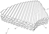
figure 2 is a perspective view of a filler segment consisting of structural planes,
figure 3 is a top view of a structured surface,
figure 4 is a cross-sectional view IV-IV of the structural plane according to figure 3,
fig. 5 and 6 are sectional views of a rotor with a structural filler ring made up of a plurality of individual ring segments.
Detailed Description
The mass transfer machine has a rotor 1 with two coaxial circular side faces 2 which are arranged parallel to one another and the intermediate space of which is filled with a filling. The filling is formed here by a plurality of individual filling sectors 3 in the form of annular sectors, so that the inner ends of the filling sectors 3 form an inner cylindrical, coaxial or cylindrical annular space 4, in which the liquid is added. The curved outer ends of the filler segments form a cylindrical outer ring 5 in which the flow channels 6 of the filler segments end.
As shown in fig. 2, each filler segment 3 is formed from a plurality of individual structured surfaces 7 lying one on top of the other, wherein the structured surfaces 7 are formed in a wave-like manner. The waves are designed such that they are sawtooth-shaped in cross section (as shown in fig. 4) or else comprise rounded waves.
The mutually parallel waves of each structural surface 7 form flow channels 6 in the wave troughs thereof, wherein the structural surfaces lying against one another are rotated relative to one another and are therefore arranged at an angle to one another, in particular at right angles to one another, such that between the two structural surfaces the flow channels cross one another as can be seen from fig. 2.
Preferably, the filler segments each consist of 3 to 150, preferably 5 to 25, structural surfaces lying one on top of the other. Furthermore, the structural filler located in the rotor consists of 2 to 64 filler segments, as shown in fig. 1.
Alternatively, however, the structural filler of the rotary part can also consist of a structural filler ring which is coaxial to one another and which is in turn divided into individual ring segments, as shown in fig. 5 and 6.
The structured surface 7 is made either of an all-metal and/or plastic wire tape, woven or knitted fabric or of glass fibers, wherein the wires preferably have a diameter of 0.1 to 0.5mm, preferably 0.15 to 0.2 mm. Alternatively, however, the structured surface 7 can also be formed by a screen or grid made of metal or plastic.
The structured surfaces 7 of the filler segments 3 are preferably spot-welded to one another by means of a laser beam.
Claims (16)
1. Device for inducing mass transfer between a liquid and a gas inside a rotor (1) with a filling, wherein the liquid is added in the center of the rotor and is driven outwards through the filling by the centrifugal force generated by the rotation of the rotor, and the gas surrounds the rotor and is pressed through the rotor from the outside inwards against the flow of the liquid in the rotor by the gas pressure, characterized in that the filling located in the rotor (1) is divided into a plurality of individual filling sectors (3) which are adjacent to one another in the circumferential direction to form a circular disk together, wherein each ring sector-shaped filling sector (3) is formed by at least one structural filling which is formed by a plurality of woven, knitted, mesh or grid-shaped structural faces (7) which are axially superimposed on one another, the structural surface is made of metal or plastic or glass fiber, and the rotation axis of the rotating part is perpendicular to the structural surface.
2. The device according to claim 1, characterized in that the structured surfaces (7) are wave-shaped, wherein the waves of each structured surface are parallel to each other.
3. The apparatus of claim 2, wherein the structured surface waves are saw-toothed in cross-section.
4. A device according to claim 2, characterized in that the waves of one structured surface (7) are arranged obliquely with respect to the waves of the adjacent structured surface, so that there are cross flow channels between the two structured surfaces.
5. Device according to any of claims 1-4, characterized in that the structured surface (7) is made of metal and/or plastic wires or of sheet metal strips or glass fibers.
6. The device according to claim 5, wherein the metal and/or plastic wires have a diameter of 0.1 to 0.5 mm.
7. Device according to any of claims 1-4, characterized in that the structural filler located in the rotating member consists of 2 to 64 filler sectors (3).
8. Device according to any of claims 1-4, characterized in that the inner ends of the filler sectors (3) form an inner, cylindrical, coaxial annular space (4) from which the flow channel emanates and into which the liquid is added.
9. Device according to any of claims 1-4, characterized in that the outer ends of the filler sectors (3) form an outer cylindrical ring (5) in which the flow channels (6) of the filler sectors end.
10. The device according to any of claims 1 to 4, characterized in that the filler sectors (3) consist of 3 to 150 structured surfaces (7) on top of each other.
11. Device according to any one of claims 1 to 4, characterized in that the structured faces of the filler sectors (3) are spot-welded to each other by means of a laser beam.
12. The device according to any of claims 1 to 4, characterized in that the structural filler of the rotating member (1) consists of structural filler rings (10) coaxial to each other, which are divided into individual ring segments (3).
13. Device according to any of claims 1-4, characterized in that the rotor has two circular side faces (2), the rotor axis of rotation being perpendicular to the side faces and the side faces forming an intermediate space with each other, which intermediate space is filled by filler sectors (3).
14. A device according to claim 4, characterized in that the waves of one structured surface (7) are arranged at right angles to the waves of the adjacent structured surface.
15. The device according to claim 6, wherein the metal and/or plastic wires have a diameter of 0.15 to 0.2 mm.
16. Device according to claim 10, characterized in that the filler sectors (3) consist of 5 to 25 structured surfaces (7) placed on top of each other.
Applications Claiming Priority (2)
| Application Number | Priority Date | Filing Date | Title |
|---|---|---|---|
| DE102017007861.0 | 2017-08-23 | ||
| DE102017007861.0A DE102017007861A1 (en) | 2017-08-23 | 2017-08-23 | Mass transfer machine |
Publications (2)
| Publication Number | Publication Date |
|---|---|
| CN109420357A CN109420357A (en) | 2019-03-05 |
| CN109420357B true CN109420357B (en) | 2021-10-08 |
Family
ID=63012776
Family Applications (1)
| Application Number | Title | Priority Date | Filing Date |
|---|---|---|---|
| CN201810957149.7A Active CN109420357B (en) | 2017-08-23 | 2018-08-22 | Mass transfer machine |
Country Status (6)
| Country | Link |
|---|---|
| US (1) | US10710100B2 (en) |
| EP (1) | EP3446764B1 (en) |
| JP (1) | JP7189697B2 (en) |
| CN (1) | CN109420357B (en) |
| DE (1) | DE102017007861A1 (en) |
| TW (1) | TWI791570B (en) |
Families Citing this family (1)
| Publication number | Priority date | Publication date | Assignee | Title |
|---|---|---|---|---|
| US20210381771A1 (en) * | 2020-04-23 | 2021-12-09 | Brentwood Industries, Inc. | Drift eliminator and method of making |
Citations (5)
| Publication number | Priority date | Publication date | Assignee | Title |
|---|---|---|---|---|
| EP0089128A1 (en) * | 1982-03-12 | 1983-09-21 | Imperial Chemical Industries Plc | Process for displacing dissolved gas from water |
| US5363909A (en) * | 1991-11-27 | 1994-11-15 | Praxair Technology, Inc. | Compact contacting device |
| CN101125263A (en) * | 2007-06-11 | 2008-02-20 | 刘辉 | Vertical rotating bed super gravity field equipment |
| CN101596400A (en) * | 2009-07-14 | 2009-12-09 | 薛碧 | The counter and concurrent flow water ripple ring plate fillers high gravity dedusting and desulfurizing machine |
| CN105148685A (en) * | 2015-09-23 | 2015-12-16 | 中北大学 | Constant-channel type rotating-packed-bed mass transferring and reacting device |
Family Cites Families (20)
| Publication number | Priority date | Publication date | Assignee | Title |
|---|---|---|---|---|
| GB265120A (en) * | 1926-01-26 | 1927-07-13 | Louise Theisen | Improvements in apparatus for producing pressure and suctional effects |
| GB757149A (en) * | 1953-06-29 | 1956-09-12 | Claes Wilhelm Pilo | Apparatus for the performance of an exchange of heat and/or soluble substances between two flowing media of different specific gravity |
| US2944801A (en) * | 1955-05-09 | 1960-07-12 | Katz Robert | Rotary interchanger with direct interfacial fluid contact |
| US2941872A (en) * | 1959-06-09 | 1960-06-21 | Pilo | Apparatus for intimate contacting of two fluid media having different specific weight |
| US3095149A (en) * | 1961-06-23 | 1963-06-25 | Foremost Dairies Inc | Centrifugal atomizer and method |
| US3701513A (en) * | 1970-07-21 | 1972-10-31 | Shirley J Carter | Fuel feeding apparatus |
| US3991143A (en) * | 1973-07-12 | 1976-11-09 | Carter Shirley J | Apparatus for producing and delivering a combustible fuel mixture and improved nebulizer rotor |
| EP0023745B1 (en) | 1977-12-01 | 1985-05-08 | Imperial Chemical Industries Plc | Process and apparatus for effecting mass transfer |
| ATE21043T1 (en) * | 1981-10-26 | 1986-08-15 | Ici Plc | GAS-LIQUID CENTRIFUGAL REACTOR. |
| DE3268599D1 (en) * | 1981-11-24 | 1986-02-27 | Ici Plc | Contacting device |
| ZA83242B (en) * | 1982-01-19 | 1983-11-30 | Ici Plc | The removal of hydrogen sulphide from gas streams |
| GB8305595D0 (en) * | 1983-03-01 | 1983-03-30 | Ici Plc | Evaporator |
| JP2984290B2 (en) * | 1988-09-02 | 1999-11-29 | ゲブリユーダー ズルツアー アクチエンゲゼルシヤフト | Equipment for catalytic reaction |
| JP3500983B2 (en) | 1998-09-21 | 2004-02-23 | 松下電器産業株式会社 | Multiple image forming device |
| CN103831075B (en) * | 2013-12-24 | 2016-08-17 | 北京化工大学 | A kind of electric motor built-in hypergravity swinging bed device and application thereof |
| US9987589B2 (en) | 2013-12-31 | 2018-06-05 | Hindustan Petroleum Corporation, LTD. | Rotating packed bed unit |
| US10814247B2 (en) | 2014-09-09 | 2020-10-27 | Hindustan Petroleum Corporation | Rotating packed bed assembly |
| CN104843946A (en) * | 2015-05-14 | 2015-08-19 | 上海秀特化工科技有限公司 | Supergravity wet oxidation reactor, supergravity wet oxidation sewage treating equipment and supergravity wet oxidation method |
| CN106040159B (en) * | 2016-07-13 | 2018-11-09 | 云南民族大学 | A kind of high gravity rotating packed bed device |
| CN205761206U (en) * | 2016-07-16 | 2016-12-07 | 吴一鸣 | High-gravity rotating bed pin-connected panel filler plate |
-
2017
- 2017-08-23 DE DE102017007861.0A patent/DE102017007861A1/en active Pending
-
2018
- 2018-07-18 EP EP18000608.2A patent/EP3446764B1/en active Active
- 2018-07-25 TW TW107125764A patent/TWI791570B/en active
- 2018-08-17 JP JP2018153457A patent/JP7189697B2/en active Active
- 2018-08-21 US US16/106,713 patent/US10710100B2/en active Active
- 2018-08-22 CN CN201810957149.7A patent/CN109420357B/en active Active
Patent Citations (5)
| Publication number | Priority date | Publication date | Assignee | Title |
|---|---|---|---|---|
| EP0089128A1 (en) * | 1982-03-12 | 1983-09-21 | Imperial Chemical Industries Plc | Process for displacing dissolved gas from water |
| US5363909A (en) * | 1991-11-27 | 1994-11-15 | Praxair Technology, Inc. | Compact contacting device |
| CN101125263A (en) * | 2007-06-11 | 2008-02-20 | 刘辉 | Vertical rotating bed super gravity field equipment |
| CN101596400A (en) * | 2009-07-14 | 2009-12-09 | 薛碧 | The counter and concurrent flow water ripple ring plate fillers high gravity dedusting and desulfurizing machine |
| CN105148685A (en) * | 2015-09-23 | 2015-12-16 | 中北大学 | Constant-channel type rotating-packed-bed mass transferring and reacting device |
Also Published As
| Publication number | Publication date |
|---|---|
| TW201912227A (en) | 2019-04-01 |
| EP3446764B1 (en) | 2019-11-20 |
| JP7189697B2 (en) | 2022-12-14 |
| US10710100B2 (en) | 2020-07-14 |
| CN109420357A (en) | 2019-03-05 |
| EP3446764A1 (en) | 2019-02-27 |
| TWI791570B (en) | 2023-02-11 |
| US20190060916A1 (en) | 2019-02-28 |
| JP2019037972A (en) | 2019-03-14 |
| DE102017007861A1 (en) | 2019-02-28 |
Similar Documents
| Publication | Publication Date | Title |
|---|---|---|
| JP5038789B2 (en) | Seal assembly and rotary machine with "L" shaped butt gap seal between segments | |
| US10118184B2 (en) | Centrifugal separator conical rotor disc elements having radial projections, and rotors having disc elements | |
| CN109420357B (en) | Mass transfer machine | |
| RU2013139730A (en) | VERTICAL DIAL DESIGN REACTOR | |
| RU2017144769A (en) | FLANGE SUPPORTED VALVE DISK VENICE KNOT | |
| CN107110199A (en) | Bearing foil, the method for gap geometry for adjusting bearing foil and the corresponding manufacturing method of bearing foil | |
| JP2014522719A5 (en) | ||
| JP2017538069A5 (en) | ||
| RU2017123813A (en) | PERISTALTIC PUMPS | |
| JP2017513710A5 (en) | ||
| CN109499087B (en) | Mass transfer machine | |
| JP2013503317A5 (en) | ||
| JP5250201B2 (en) | Vacuum pump | |
| US3480148A (en) | Conical honeycomb structure | |
| JP2015140909A5 (en) | Thrust bearing and thrust foil bearing | |
| JP6180358B2 (en) | Cylindrical structure and motor | |
| JP2019037972A5 (en) | ||
| JP2018531346A5 (en) | ||
| CN104895617A (en) | Bladeless turbine engine | |
| KR20190072531A (en) | Segmented support element | |
| JP6452190B2 (en) | Processing brush | |
| JP6655426B2 (en) | Suction bellmouth, vertical shaft pump, and method of manufacturing suction bellmouth | |
| US10376947B2 (en) | Multiple wire wrap screen fabrication method | |
| CN108854445B (en) | Heat exchange runner and manufacturing method thereof | |
| CN205336000U (en) | Motor stator ventilation frid |
Legal Events
| Date | Code | Title | Description |
|---|---|---|---|
| PB01 | Publication | ||
| PB01 | Publication | ||
| SE01 | Entry into force of request for substantive examination | ||
| SE01 | Entry into force of request for substantive examination | ||
| GR01 | Patent grant | ||
| GR01 | Patent grant |