CN109279109B - Automatic sabot dress dish vanning device of formula electric capacity - Google Patents
Automatic sabot dress dish vanning device of formula electric capacity Download PDFInfo
- Publication number
- CN109279109B CN109279109B CN201811069161.0A CN201811069161A CN109279109B CN 109279109 B CN109279109 B CN 109279109B CN 201811069161 A CN201811069161 A CN 201811069161A CN 109279109 B CN109279109 B CN 109279109B
- Authority
- CN
- China
- Prior art keywords
- capacitor
- sliding
- electric capacity
- slide
- moving mechanism
- Prior art date
- Legal status (The legal status is an assumption and is not a legal conclusion. Google has not performed a legal analysis and makes no representation as to the accuracy of the status listed.)
- Active
Links
Images


Classifications
-
- B—PERFORMING OPERATIONS; TRANSPORTING
- B65—CONVEYING; PACKING; STORING; HANDLING THIN OR FILAMENTARY MATERIAL
- B65B—MACHINES, APPARATUS OR DEVICES FOR, OR METHODS OF, PACKAGING ARTICLES OR MATERIALS; UNPACKING
- B65B57/00—Automatic control, checking, warning, or safety devices
- B65B57/20—Applications of counting devices for controlling the feed of articles
-
- B—PERFORMING OPERATIONS; TRANSPORTING
- B65—CONVEYING; PACKING; STORING; HANDLING THIN OR FILAMENTARY MATERIAL
- B65B—MACHINES, APPARATUS OR DEVICES FOR, OR METHODS OF, PACKAGING ARTICLES OR MATERIALS; UNPACKING
- B65B35/00—Supplying, feeding, arranging or orientating articles to be packaged
- B65B35/30—Arranging and feeding articles in groups
- B65B35/32—Arranging and feeding articles in groups by gravity
-
- B—PERFORMING OPERATIONS; TRANSPORTING
- B65—CONVEYING; PACKING; STORING; HANDLING THIN OR FILAMENTARY MATERIAL
- B65B—MACHINES, APPARATUS OR DEVICES FOR, OR METHODS OF, PACKAGING ARTICLES OR MATERIALS; UNPACKING
- B65B43/00—Forming, feeding, opening or setting-up containers or receptacles in association with packaging
- B65B43/42—Feeding or positioning bags, boxes, or cartons in the distended, opened, or set-up state; Feeding preformed rigid containers, e.g. tins, capsules, glass tubes, glasses, to the packaging position; Locating containers or receptacles at the filling position; Supporting containers or receptacles during the filling operation
- B65B43/54—Means for supporting containers or receptacles during the filling operation
- B65B43/60—Means for supporting containers or receptacles during the filling operation rotatable
-
- B—PERFORMING OPERATIONS; TRANSPORTING
- B65—CONVEYING; PACKING; STORING; HANDLING THIN OR FILAMENTARY MATERIAL
- B65B—MACHINES, APPARATUS OR DEVICES FOR, OR METHODS OF, PACKAGING ARTICLES OR MATERIALS; UNPACKING
- B65B5/00—Packaging individual articles in containers or receptacles, e.g. bags, sacks, boxes, cartons, cans, jars
- B65B5/10—Filling containers or receptacles progressively or in stages by introducing successive articles, or layers of articles
- B65B5/101—Filling containers or receptacles progressively or in stages by introducing successive articles, or layers of articles by gravity
Landscapes
- Engineering & Computer Science (AREA)
- Mechanical Engineering (AREA)
- Container Filling Or Packaging Operations (AREA)
- Fixed Capacitors And Capacitor Manufacturing Machines (AREA)
Abstract
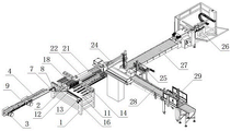
The utility model provides an automatic sabot vanning device of cartridge clip formula electric capacity, includes frame (1), its characterized in that: the automatic tray filling machine is characterized in that a slide way (2) is arranged on one side above the rack (1), a capacitor conveying device is installed on the outer side of the slide way (2), a capacitor inlet is formed in the upper end of the outer side of the slide way (2), a capacitor tray filling device is installed in a butt joint mode on the capacitor inlet, a carton conveying roller way (27) is arranged on one side of a three-axis manipulator (25), an unpacking machine (26) is installed at the front end of the carton conveying roller way (27), a discharging conveying roller way (28) is arranged on the other side of the three-axis manipulator (25), and an automatic box sealing machine (29) is installed at a rear end outlet of the discharging conveying roller way (28).
Description
Technical Field
The invention relates to a capacitor tray-loading and boxing device, in particular to an automatic cartridge clip type capacitor tray-loading and boxing device, and belongs to the technical field of packaging equipment.
Background
The capacitor is a common electronic component, the using amount of the capacitor is very large, and a capacitor manufacturer needs to load the capacitor plates after completing capacitor production, and then put a plurality of capacitor plates together for boxing and delivery. At present, the automation degree of capacitor tray loading is very low, manual operation is relied on to a great extent, common manual tray loading tools are mainly adopted for carrying out the tray loading, the efficiency of the tray loading mode is low, the consistency of manual tray loading is poor, the condition that individual capacitors are placed in position and are missed easily occurs, and the tray loading effect is poor. In addition, the existing capacitor boxing depends on manual operation to a great extent, the boxing efficiency is low, the labor intensity of workers is high, and the requirement of efficient tray boxing of large-batch capacitors cannot be met.
Disclosure of Invention
The invention aims to solve the problems that the automation degree of the existing capacitor tray loading and boxing is very low, manual operation is greatly depended on, the consistency of manual tray loading is poor, the tray loading efficiency is very low, meanwhile, manual operation is required for boxing, and the defects that the requirement of large-batch efficient tray loading and boxing of capacitors cannot be met.
In order to achieve the purpose, the technical solution of the invention is as follows: the utility model provides an automatic sabot vanning device of cartridge clip formula electric capacity, includes the frame, its characterized in that including the frame: a slideway is arranged on one side above the rack, a capacitor conveying device is arranged on the outer side of the slideway, a capacitor inlet is arranged at the upper end of the outer side of the slideway, a sliding plate is horizontally arranged at the lower end of the slideway, the sliding plate is installed on the rack through a reciprocating mechanism, a capacitor falling hole is formed in the sliding plate and corresponds to a capacitor placing position on a capacitor disc, a plurality of inserting plates are installed on an installation seat right above the sliding plate at equal intervals, rollers are installed at the upper ends of the inserting plates, springs are sleeved on the inserting plates, one ends of the springs are abutted to bosses of the inserting plates, the other ends of the springs are abutted to the installation seat, a groove-shaped sliding rail is fixed on the rack above the outer side of the inserting plates, a sliding block is horizontally installed on the groove-shaped sliding rail, an; an empty capacitor plate placing device is installed on the outer side of the sliding plate, a three-axis manipulator is arranged on the outer side of the empty capacitor plate placing device, a carton conveying roller way is arranged on one side of the three-axis manipulator, an unpacking machine is installed at the front end of the carton conveying roller way, an ejection conveying roller way is arranged on the other side of the three-axis manipulator, and an automatic carton sealing machine is installed at the rear end outlet of the ejection conveying roller way.
The electric capacity conveyor includes conveyor belt wheel, the electric capacity conveyer belt, sliding tray and electric capacity runner, a pair of conveyor belt wheel is installed in the outside of slide, conveyor belt wheel is connected with driving motor, the last electric capacity conveyer belt that is provided with of conveyor belt wheel, evenly be provided with the arc wall corresponding with electric capacity on the surface of electric capacity conveyer belt, conveyor belt wheel's terminal lower part is provided with the sliding tray, the exit end below of sliding tray is provided with the electric capacity runner, the last wheel reason tangent line of electric capacity runner coincides mutually with the glide plane of sliding tray, the electric capacity runner links up mutually with the electric capacity inlet port of slide outside upper end.
The upper surface of electric capacity conveyer belt is provided with the guide board that is the arc and arranges or slope and arrange, and the outward flange of electric capacity conveyer belt is pressed close to the guide board that electric capacity conveyer belt got into the end, and the outside of sliding tray is pressed close to the guide board that is close to electric capacity conveyer belt output, and the limiting plate is installed near the one end of sliding tray in the edge outside of electric capacity conveyer belt.
The reciprocating mechanism comprises a rack, a gear, a linear guide rail, a sliding seat and a servo motor, the sliding seat is fixed on two sides of the sliding plate, the linear guide rail is installed on the sliding seat, a fixing surface of the linear guide rail is fixed with the rack, the servo motor is installed on the outer side of the rack, the gear is coaxially fixed on an output shaft of the servo motor, the rack is fixed on the sliding seat along the moving direction, and the rack is meshed with the gear.
The outer side end section of the slideway is provided with an arc-shaped slideway or an inclined plane slideway, and a capacitor inlet at the outer end of the slideway is higher than the inner side horizontal section of the slideway.
Photoelectric counters are installed on two sides of the slide way, a movable material separator is installed in the middle of the slide way and matched with the photoelectric counters, and a blocking plate blocking capacitors and a driving device are installed inside the movable material separator.
The lower surface of the slider is smooth and is lower than the maximum height of the upper end of the roller when the spring is not compressed.
The empty capacitor disc placing device comprises a transverse moving mechanism, a longitudinal moving mechanism, a vertical moving mechanism and a capacitor disc grabbing device, wherein the longitudinal moving mechanism is installed on a sliding piece of the transverse moving mechanism, the vertical moving mechanism is installed on a sliding piece of the longitudinal moving mechanism, and the capacitor disc grabbing device is installed on a lifting block of the vertical moving mechanism.
The invention has the beneficial effects that:
1. the invention adopts the capacitor conveying device, can realize the orderly arrangement of the capacitors in the process of conveying the capacitors and feeding the capacitors, can also carry out induction counting through the photoelectric counter, can block the capacitors which are not counted by the material separator after a counting period is finished, and simultaneously realizes the equal-interval separation of the adjacent capacitors through the extrusion of the inserting plate and the sliding block mechanism.
2. The sliding plate intermittently moves under the driving of the reciprocating mechanism, the stations are continuously changed forward, the capacitors in the same row can fall onto the capacitor placing positions on the capacitor tray through the capacitor falling holes each time of tray loading operation, the sliding plate is matched with the slide way and the inserting plate to realize the sequential and accurate tray loading operation of the capacitor tray, the tray loading efficiency is high, and automatic box loading and box sealing operation is performed after the tray loading is finished.
3. The tray loading device has the advantages of reasonable structure, high automation degree, no need of manual operation and intervention, doubled tray loading efficiency, good tray loading effect, realization of automatic box loading and box sealing, and effective solution of the technical problem that the conventional capacitor is time-consuming and labor-consuming in tray loading and box loading.
Drawings
Fig. 1 is a schematic structural view of the present invention.
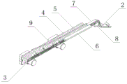
Fig. 2 is a side schematic view of the present invention.
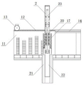
Fig. 3 is a schematic structural diagram of the capacitor transferring apparatus of the present invention.
Fig. 4 is a schematic structural view of the disc loading device of the present invention.
Fig. 5 is a side schematic view of fig. 4.
Fig. 6 is a top view of fig. 4.
In the figure: the device comprises a rack 1, a slideway 2, a conveyor belt wheel 3, a capacitor conveyor belt 4, a guide plate 5, a limiting plate 6, a sliding groove 7, a capacitor rotating wheel 8, a capacitor 9, a material separator 10, a sliding plate 11, a rack 12, a gear 13, a linear guide rail 14, a sliding seat 15, a servo motor 16, a mounting seat 17, an inserting plate 18, a spring 19, a roller 20, a groove-shaped sliding rail 21, a sliding block 22, an air cylinder 23, an empty capacitor plate placing device 24, a three-axis manipulator 25, a case unpacking machine 26, a carton conveying roller way 27, an ejection of compact conveying roller way 28 and an automatic case sealing machine 29.
Detailed Description
The invention is described in further detail below with reference to the following description of the drawings and the detailed description.
Referring to fig. 1 to 6, the automatic cartridge clip type capacitor disc loading and boxing device of the present invention includes a frame 1, and is characterized in that: a slideway 2 is arranged on one side above the rack 1, a capacitor conveying device is arranged on the outer side of the slideway 2, a capacitor inlet is arranged at the upper end of the outer side of the slideway 2, a sliding plate 11 is horizontally arranged at the lower end of the slideway 2, the sliding plate 11 is arranged on the rack 1 through a reciprocating mechanism, a capacitor falling hole is formed in the sliding plate 11 and corresponds to a capacitor placing position on a capacitor disc, a plurality of inserting plates 18 are arranged on a mounting seat 17 right above the sliding plate 11 at equal intervals, rollers 20 are arranged at the upper ends of the inserting plates 18, springs 19 are sleeved on the inserting plates 18, one ends of the springs 19 are propped against bosses of the inserting plates 18, the other ends of the springs 19 are propped against the mounting seat 17, slot-shaped slide rails 21 are fixed on the rack 1 above the outer sides of the inserting plates, the upper part of the frame 1 is provided with a cylinder 23, and the telescopic end of the cylinder 23 is hinged with the upper surface of the sliding block 22; an empty capacitor plate placing device 24 is installed on the outer side of the sliding plate 11, a three-axis manipulator 25 is arranged on the outer side of the empty capacitor plate placing device 24, a carton conveying roller way 27 is arranged on one side of the three-axis manipulator 25, an unpacking machine 26 is installed at the front end of the carton conveying roller way 27, an discharging conveying roller way 28 is arranged on the other side of the three-axis manipulator 25, and an automatic packing machine 29 is installed at the rear end outlet of the discharging conveying roller way 28.
Electric capacity conveyor includes band pulley 3, electric capacity conveyer belt 4, sliding tray 7 and electric capacity runner 8, a pair of band pulley 3 is installed in slide 2's the outside, band pulley 3 is connected with driving motor, be provided with electric capacity conveyer belt 4 on band pulley 3, evenly be provided with the arc wall corresponding with electric capacity 9 on electric capacity conveyer belt 4's the surface, band pulley 3's terminal lower part is provided with sliding tray 7, sliding tray 7's exit end below is provided with electric capacity runner 8, electric capacity runner 8's last wheel reason tangent line coincides mutually with sliding surface of sliding tray 7, electric capacity runner 8 links up mutually with the electric capacity inlet port of slide 2 outside upper end.
The upper surface of electric capacity conveyer belt 4 is provided with and is the arc to arrange or slope guide board 5 of arranging, and the outward flange of electric capacity conveyer belt 4 is pressed close to guide board 5 that electric capacity conveyer belt 4 got into the end, and the outside of sliding tray 7 is pressed close to guide board 5 that electric capacity conveyer belt 4 output, and limiting plate 6 is installed to the one end that the edge outside of electric capacity conveyer belt 4 is close to sliding tray 7.
The reciprocating mechanism comprises a rack 12, a gear 13, a linear guide rail 14, a sliding seat 15 and a servo motor 16, wherein the sliding seat 15 is fixed on two sides of the sliding plate 11, the linear guide rail 14 is installed on the sliding seat 15, a fixing surface of the linear guide rail 14 is fixed with the rack 1, the servo motor 16 is installed on the outer side of the rack 1, the gear 13 is coaxially fixed on an output shaft of the servo motor 16, the rack 12 is fixed on the sliding seat 15 along the moving direction, and the rack 12 is meshed with the gear 13.
The outer side end section of the slide way 2 is provided with an arc-shaped slide way or an inclined plane slide way, and a capacitor inlet at the outer end of the slide way 2 is higher than the inner side horizontal section of the slide way 2.
Photoelectric counters are installed on two sides of the slide 2, a movable material separator 10 is installed in the middle of the slide 2 and matched with the photoelectric counters, and a blocking plate and a driving device for blocking capacitors are installed inside the movable material separator 10.
The lower surface of the slider 22 is smooth and the lower surface of the slider 22 is lower than the maximum height of the upper end of the roller 20 when the spring 19 is not compressed.
The empty capacitor plate placing device 24 comprises a transverse moving mechanism, a longitudinal moving mechanism, a vertical moving mechanism and a capacitor plate grabbing device, wherein the longitudinal moving mechanism is installed on a sliding part of the transverse moving mechanism, the vertical moving mechanism is installed on a sliding part of the longitudinal moving mechanism, and the capacitor plate grabbing device is installed on a lifting block of the vertical moving mechanism.
Referring to fig. 1 to 6, a slide way 2 is fixedly arranged above the outer side of the frame 1, a capacitor inlet is arranged at the upper end of the outer side of the slide way 2, a horizontal section is arranged at the lower end of the slide way 2, and the horizontal section of the slide way 2 is butted with a slide plate 11 which is horizontally arranged. The outer side end section of the slide way 2 is provided with an arc-shaped slide way or an inclined plane slide way, a capacitor inlet opening at the outer end of the slide way 2 is higher than the inner side horizontal section of the slide way 2, and capacitors sequentially enter the slide way from the capacitor inlet opening at the outer end of the slide way 2 and then slide downwards along the slide way 2 and enter the sliding plate 11. Electric capacity conveyor is installed in slide 2's the outside, electric capacity conveyor is used for entering into slide 2 with carrying of electric capacity one, electric capacity conveyor includes band pulley 3, electric capacity conveyer belt 4, sliding tray 7 and electric capacity runner 8, a pair of band pulley 3 is installed in slide 2's the outside, band pulley 3 is connected with driving motor, be provided with electric capacity conveyer belt 4 on the band pulley 3, evenly be provided with the arc wall corresponding with electric capacity 9 on electric capacity conveyer belt 4's the surface, driving motor drives band pulley 3 at the uniform velocity and rotates, thereby drive electric capacity conveyer belt 4 and rotate, and then realize the belt transport to electric capacity.
The terminal lower part of band pulley 3 is provided with sliding tray 7, the exit end below of sliding tray 7 is provided with electric capacity runner 8, sliding tray 7 and electric capacity runner 8 are for realizing linking up and electric capacity between electric capacity conveyer belt 4 and the slide 2 and carry, electric capacity runner 8's top rim tangent line coincides with the glide plane of sliding tray 7 mutually, electric capacity runner 8 links up with the electric capacity inlet port of the 2 outside upper ends of slide mutually, it can fall into the arc wall of electric capacity runner 8 one side in proper order to enter into sliding tray 7, under electric capacity runner 8's rotation effect, electric capacity on the electric capacity runner 8 can fall from the opposite side, and enter into in the slide 2. The upper surface of electric capacity conveyer belt 4 is provided with and is the arc to arrange or slope guide board 5 of arranging, the outward flange that is close to electric capacity conveyer belt 4 entering one end of guide board 5 of electric capacity conveyer belt 4, the outside that is close to electric capacity conveyer belt 4 output one end of guide board 5 is close to sliding tray 7, limiting plate 6 is installed near the one end of sliding tray 7 in the edge outside of electric capacity conveyer belt 4, guide board 5 and 6 cooperation use of limiting plate just make the alignment sliding tray 7 that the electric capacity that is located on electric capacity conveyer belt 4 can arrange in order, the electric capacity is avoided carrying the disorder.
The sliding plate 11 is installed on the frame 1 through a reciprocating mechanism, and the reciprocating mechanism is used for driving the sliding plate 11 to move back and forth in the horizontal direction. The reciprocating mechanism comprises a rack 12, a gear 13, a linear guide rail 14, a sliding seat 15 and a servo motor 16, wherein the sliding seat 15 is fixed on two sides of the sliding plate 11, the linear guide rail 14 is installed on the sliding seat 15, a fixing surface of the linear guide rail 14 is fixed with the rack 1, the servo motor 16 is installed on the outer side of the rack 1, the gear 13 is coaxially fixed on an output shaft of the servo motor 16, the rack 12 is fixed on the sliding seat 15 along the moving direction, and the rack 12 is meshed with the gear 13. The servo motor 16 drives the gear 13 to rotate, and the gear 13 drives the rack 12 to move, thereby driving the sliding seat 15 and the sliding plate 11 to move back and forth.
A plurality of inserting plates 18 are arranged on a mounting seat 17 right above a sliding plate 11 at equal intervals, the mounting seat 17 is fixed on the upper portion of a rack 1, each inserting plate 18 can move up and down within a certain range, after moving downwards, the inserting plates 18 can separate capacitors which are located on the sliding plate 11 and are close to one another respectively, a certain distance is separated between adjacent capacitors under the action of the inserting plates 18, and the transverse size of the lower ends of the inserting plates 18 is the same as the distance separating the adjacent capacitors. The upper end of the inserting plate 18 is provided with a roller 20, the inserting plate 18 is sleeved with a spring 19, the spring 19 plays a role of upwards resetting the inserting plate 18, one end of the spring 20 is propped against a boss of the inserting plate 18, and the other end of the spring 20 is propped against the mounting seat 17.
A groove-shaped slide rail 21 is fixed on the rack 1 above the outer side of the inserting plate 18, a slide block 22 is horizontally arranged on the groove-shaped slide rail 21, and the slide block 22 has certain weight and can slide left and right along the groove-shaped slide rail 21. The upper portion of frame 1 is installed cylinder 23 or other drive disk assembly, and the flexible end of cylinder 23 is articulated mutually with the upper surface of slider 22, and cylinder 23 or other drive disk assembly can drive slider 22 and realize moving about. The lower surface of the sliding block 22 is smooth, one side of the sliding block 22 close to the roller 20 is set to be an inclined surface, and the lower surface of the sliding block 22 is lower than the maximum height of the upper end of the roller 20 when the spring 19 is not compressed, as shown in fig. 4, during the leftward sliding process of the sliding block 22, the lower surface of the sliding block 22 or the roller 20 is sequentially pressed downwards, the inserting plate 18 moves downwards to separate the capacitors which are closely arranged, and the spring 19 is compressed. When the air cylinder 23 or other driving parts can drive the slide block 22 to move rightwards, the rollers 20 are sequentially reset and bounced upwards from left to right, the inserting plate 18 is reset upwards under the action of the spring 19, the lower end of the inserting plate 18 is separated, and the next cycle of action is waited.
An empty capacitor disc placing device 24 is installed on the outer side of the sliding plate 11, the empty capacitor disc placing device 24 comprises a transverse moving mechanism, a longitudinal moving mechanism, a vertical moving mechanism and a capacitor disc grabbing device, the longitudinal moving mechanism is installed on a sliding part of the transverse moving mechanism, the vertical moving mechanism is installed on a sliding part of the longitudinal moving mechanism, and the capacitor disc grabbing device is installed on a lifting block of the vertical moving mechanism. The three-axis manipulator 25 is arranged on the outer side of the empty capacitor plate placing device 24, a carton conveying roller way 27 is arranged on one side of the three-axis manipulator 25, an unpacking machine 26 is installed at the front end of the carton conveying roller way 27, the carton conveying roller way 27 is used for horizontally conveying empty cartons to the next process, and the carton conveying roller way 27 further has a centering and positioning function. The box unpacking machine 26 can stretch and open the flat paper box, automatically fold the bottom of the paper box and automatically close the box bottom, so that the paper box is in a box shape with the upper end opened.
The opposite side of triaxial manipulator 25 is provided with ejection of compact rollgang 28, and automatic case sealer 29 is installed in ejection of compact rollgang 28's rear end exit, and ejection of compact rollgang 28 is used for the carton that horizontal transport vanning was accomplished, carries it to automatic case sealer 29 and encapsulates the packing, and automatic case sealer 29 can automatic upper cover of folding the carton to from top to bottom automatic rubberizing tape, realize automatic case sealing, the whole process of vanning has realized automaticly.
Claims (8)
1. The utility model provides an automatic sabot vanning device of cartridge clip formula electric capacity, includes frame (1), its characterized in that: the device is characterized in that a slide way (2) is arranged on one side of the upper part of a rack (1), a capacitor conveying device is installed on the outer side of the slide way (2), a capacitor inlet is formed in the upper end of the outer side of the slide way (2), a slide plate (11) is horizontally arranged at the lower end of the slide way (2), the slide plate (11) is installed on the rack (1) through a reciprocating mechanism, a hole for dropping a capacitor is formed in the slide plate (11), the hole for dropping the capacitor corresponds to a capacitor placing position on a capacitor tray, a plurality of plug boards (18) are installed on a mounting seat (17) right above the slide plate (11) at equal intervals, rollers (20) are installed at the upper ends of the plug boards (18), springs (19) are sleeved on the plug boards (18), one ends of the springs (19) are propped against bosses of the plug boards (18), the other ends of the springs (19) are propped against the mounting seat (, a sliding block (22) is horizontally arranged on the groove-shaped sliding rail (21), an air cylinder (23) is arranged at the upper part of the rack (1), and the telescopic end of the air cylinder (23) is hinged with the upper surface of the sliding block (22); an empty capacitor plate placing device (24) is installed on the outer side of the sliding plate (11), a three-axis manipulator (25) is arranged on the outer side of the empty capacitor plate placing device (24), a carton conveying roller way (27) is arranged on one side of the three-axis manipulator (25), a box unpacking machine (26) is installed at the front end of the carton conveying roller way (27), an discharging conveying roller way (28) is arranged on the other side of the three-axis manipulator (25), and an automatic box sealing machine (29) is installed at the rear end outlet of the discharging conveying roller way (28).
2. The cartridge-type capacitor automatic loading and boxing device as claimed in claim 1, wherein: the capacitor conveying device comprises a conveying belt wheel (3), a capacitor conveying belt (4), a sliding groove (7) and a capacitor rotating wheel (8), wherein a pair of conveying belt wheels (3) is installed on the outer side of the sliding rail (2), the conveying belt wheels (3) are connected with a driving motor, the capacitor conveying belt (4) is arranged on the conveying belt wheels (3), arc-shaped grooves corresponding to capacitors (9) are uniformly formed in the outer surface of the capacitor conveying belt (4), the sliding groove (7) is formed in the lower portion of the tail end of the conveying belt wheels (3), the capacitor rotating wheel (8) is arranged below the outlet end of the sliding groove (7), the tangent line of the upper wheel edge of the capacitor rotating wheel (8) coincides with the sliding surface of the sliding groove (7), and the capacitor rotating wheel (8) is connected with a capacitor inlet at.
3. The cartridge-type capacitor automatic loading and boxing device as claimed in claim 2, wherein: the upper surface of electric capacity conveyer belt (4) is provided with and is the arc to arrange or slope guide board (5) of arranging, and the outward flange of electric capacity conveyer belt (4) is pressed close to in guide board (5) that is close to electric capacity conveyer belt (4) entering end, and the outside of sliding tray (7) is pressed close to in guide board (5) that is close to electric capacity conveyer belt (4) output, and limiting plate (6) are installed to the edge outside of electric capacity conveyer belt (4) near the one end of sliding tray (7).
4. The cartridge-type capacitor automatic loading and boxing device as claimed in claim 1, wherein: reciprocating motion mechanism includes rack (12), gear (13), linear guide (14), sliding seat (15) and servo motor (16), sliding seat (15) are fixed in the both sides of slide (11), install linear guide (14) on sliding seat (15), the stationary plane and frame (1) of linear guide (14) are fixed mutually, servo motor (16) are installed to the outside of frame (1), coaxial gear (13) that is fixed with on the output shaft of servo motor (16), be fixed with rack (12) along the direction of movement on sliding seat (15), rack (12) and gear (13) mesh mutually.
5. The cartridge-type capacitor automatic loading and boxing device as claimed in claim 1, wherein: the outer side end section of the slide way (2) is provided with an arc-shaped slide way or an inclined plane slide way, and a capacitor inlet at the outer end of the slide way (2) is higher than the inner side horizontal section of the slide way (2).
6. The cartridge-type capacitor automatic loading and boxing device as claimed in claim 1, wherein: photoelectric counters are installed on two sides of the slide (2), a movable material separator (10) is installed in the middle of the slide (2) and matched with the photoelectric counters, and a blocking plate blocking capacitors and a driving device are installed inside the movable material separator (10).
7. The cartridge-type capacitor automatic loading and boxing device as claimed in claim 1, wherein: the lower surface of the sliding block (22) is smooth, and the lower surface of the sliding block (22) is lower than the maximum height of the upper end of the roller (20) when the spring (19) is not compressed.
8. The cartridge-type capacitor automatic loading and boxing device as claimed in claim 1, wherein: the empty capacitor disc placing device (24) comprises a transverse moving mechanism, a longitudinal moving mechanism, a vertical moving mechanism and a capacitor disc grabbing device, wherein the longitudinal moving mechanism is installed on a sliding piece of the transverse moving mechanism, the vertical moving mechanism is installed on a sliding piece of the longitudinal moving mechanism, and the capacitor disc grabbing device is installed on a lifting block of the vertical moving mechanism.
Priority Applications (1)
| Application Number | Priority Date | Filing Date | Title |
|---|---|---|---|
| CN201811069161.0A CN109279109B (en) | 2018-09-13 | 2018-09-13 | Automatic sabot dress dish vanning device of formula electric capacity |
Applications Claiming Priority (1)
| Application Number | Priority Date | Filing Date | Title |
|---|---|---|---|
| CN201811069161.0A CN109279109B (en) | 2018-09-13 | 2018-09-13 | Automatic sabot dress dish vanning device of formula electric capacity |
Publications (2)
| Publication Number | Publication Date |
|---|---|
| CN109279109A CN109279109A (en) | 2019-01-29 |
| CN109279109B true CN109279109B (en) | 2020-11-03 |
Family
ID=65180565
Family Applications (1)
| Application Number | Title | Priority Date | Filing Date |
|---|---|---|---|
| CN201811069161.0A Active CN109279109B (en) | 2018-09-13 | 2018-09-13 | Automatic sabot dress dish vanning device of formula electric capacity |
Country Status (1)
| Country | Link |
|---|---|
| CN (1) | CN109279109B (en) |
Families Citing this family (2)
| Publication number | Priority date | Publication date | Assignee | Title |
|---|---|---|---|---|
| CN110406971B (en) * | 2019-08-22 | 2023-12-26 | 中车青岛四方车辆研究所有限公司 | Lithium capacitor inserting machine and lithium capacitor inserting method |
| CN113978835B (en) * | 2021-11-19 | 2022-11-08 | 湖北工业大学 | Press from both sides and get transfer device based on assembly line |
Family Cites Families (8)
| Publication number | Priority date | Publication date | Assignee | Title |
|---|---|---|---|---|
| DE19821969A1 (en) * | 1998-05-18 | 1999-11-25 | Focke & Co | Device for packaging groups of (single) packs |
| US7334379B1 (en) * | 2000-11-01 | 2008-02-26 | Mts Medication Technologies, Inc. | Automated solid pharmaceutical product packaging machine |
| CN103272782A (en) * | 2013-04-28 | 2013-09-04 | 广州奥迪通用照明有限公司 | Automated manufacture system of LED lamp and working method thereof |
| CN105539925A (en) * | 2016-02-04 | 2016-05-04 | 柳州市妇幼保健院 | Suction head quick boxing device |
| CN105831359A (en) * | 2016-05-29 | 2016-08-10 | 张玲玲 | Machining process for liquorice tea |
| CN106043790B (en) * | 2016-07-20 | 2018-04-17 | 华侨大学 | Fruit wrap |
| CN206719695U (en) * | 2017-04-24 | 2017-12-08 | 武汉人天机器人工程有限公司 | A kind of automatic arranging arrangement cartoning system of bottle embryo |
| CN207078385U (en) * | 2017-07-31 | 2018-03-09 | 漳州佳龙科技股份有限公司 | A kind of automatic boxing machine |
-
2018
- 2018-09-13 CN CN201811069161.0A patent/CN109279109B/en active Active
Also Published As
| Publication number | Publication date |
|---|---|
| CN109279109A (en) | 2019-01-29 |
Similar Documents
| Publication | Publication Date | Title |
|---|---|---|
| CN104773313B (en) | A kind of aseptic bag milk bag gift box boxing system | |
| CN109279109B (en) | Automatic sabot dress dish vanning device of formula electric capacity | |
| CN111136443A (en) | Automatic voltage iron core assembling equipment | |
| CN111806765A (en) | Automatic boxing machine for pipetting tips | |
| CN209889236U (en) | Bagged milk powder boxing workstation | |
| CN109335077B (en) | Multi-grade fruit classification and boxing system | |
| CN204623945U (en) | Battery finished product clamping and conveying device | |
| CN109625431A (en) | A kind of full-automatic material management and packaging facilities of shaft-like workpiece | |
| CN214877181U (en) | A fortune material device for production of textile fiber raw materials | |
| CN106743199B (en) | Rotary conveying mechanism | |
| CN109625884B (en) | Automatic production line based on intelligent assembling mechanism | |
| CN115676018A (en) | Efficient rotary table conveyor for carton packaging and capable of automatically stacking, counting and counting | |
| CN110654610A (en) | Feeding mechanism for rod-shaped materials | |
| CN116573230A (en) | Bottom plate folding mechanism of zongzi cartoning machine | |
| CN109292391A (en) | A kind of fragrant system of full-automatic receipts | |
| CN214931038U (en) | Chalk boxing machine | |
| CN114476187A (en) | Special-shaped cigarette packet production line | |
| CN210823023U (en) | Packaging equipment | |
| CN210553233U (en) | Full-automatic mosquito-repellent incense coil production device integrating forming and blank collection | |
| CN112265702B (en) | Automatic lamination boxing equipment for strip bagged products | |
| CN115009601A (en) | Double-station bagging and sealing equipment | |
| CN212333080U (en) | Automatic boxing machine for pipetting tips | |
| CN210063492U (en) | Inner and outer box integrated machine | |
| CN114044214A (en) | Automatic conveyor that opens and shuts of many specifications carton | |
| CN109018491B (en) | Medicine bottle packing device |
Legal Events
| Date | Code | Title | Description |
|---|---|---|---|
| PB01 | Publication | ||
| PB01 | Publication | ||
| SE01 | Entry into force of request for substantive examination | ||
| SE01 | Entry into force of request for substantive examination | ||
| GR01 | Patent grant | ||
| GR01 | Patent grant |