CN108449936B - Liquid removing device - Google Patents
Liquid removing device Download PDFInfo
- Publication number
- CN108449936B CN108449936B CN201680076531.6A CN201680076531A CN108449936B CN 108449936 B CN108449936 B CN 108449936B CN 201680076531 A CN201680076531 A CN 201680076531A CN 108449936 B CN108449936 B CN 108449936B
- Authority
- CN
- China
- Prior art keywords
- opposing
- slot
- groove
- liquid
- apertures
- Prior art date
- Legal status (The legal status is an assumption and is not a legal conclusion. Google has not performed a legal analysis and makes no representation as to the accuracy of the status listed.)
- Active
Links
Images


Classifications
-
- B—PERFORMING OPERATIONS; TRANSPORTING
- B08—CLEANING
- B08B—CLEANING IN GENERAL; PREVENTION OF FOULING IN GENERAL
- B08B5/00—Cleaning by methods involving the use of air flow or gas flow
- B08B5/02—Cleaning by the force of jets, e.g. blowing-out cavities
- B08B5/023—Cleaning travelling work
- B08B5/026—Cleaning moving webs
-
- B—PERFORMING OPERATIONS; TRANSPORTING
- B05—SPRAYING OR ATOMISING IN GENERAL; APPLYING FLUENT MATERIALS TO SURFACES, IN GENERAL
- B05B—SPRAYING APPARATUS; ATOMISING APPARATUS; NOZZLES
- B05B1/00—Nozzles, spray heads or other outlets, with or without auxiliary devices such as valves, heating means
- B05B1/005—Nozzles or other outlets specially adapted for discharging one or more gases
-
- B—PERFORMING OPERATIONS; TRANSPORTING
- B65—CONVEYING; PACKING; STORING; HANDLING THIN OR FILAMENTARY MATERIAL
- B65H—HANDLING THIN OR FILAMENTARY MATERIAL, e.g. SHEETS, WEBS, CABLES
- B65H20/00—Advancing webs
- B65H20/14—Advancing webs by direct action on web of moving fluid
-
- F—MECHANICAL ENGINEERING; LIGHTING; HEATING; WEAPONS; BLASTING
- F26—DRYING
- F26B—DRYING SOLID MATERIALS OR OBJECTS BY REMOVING LIQUID THEREFROM
- F26B13/00—Machines and apparatus for drying fabrics, fibres, yarns, or other materials in long lengths, with progressive movement
-
- F—MECHANICAL ENGINEERING; LIGHTING; HEATING; WEAPONS; BLASTING
- F26—DRYING
- F26B—DRYING SOLID MATERIALS OR OBJECTS BY REMOVING LIQUID THEREFROM
- F26B21/00—Arrangements or duct systems, e.g. in combination with pallet boxes, for supplying and controlling air or gases for drying solid materials or objects
- F26B21/004—Nozzle assemblies; Air knives; Air distributors; Blow boxes
-
- B—PERFORMING OPERATIONS; TRANSPORTING
- B65—CONVEYING; PACKING; STORING; HANDLING THIN OR FILAMENTARY MATERIAL
- B65H—HANDLING THIN OR FILAMENTARY MATERIAL, e.g. SHEETS, WEBS, CABLES
- B65H2301/00—Handling processes for sheets or webs
- B65H2301/50—Auxiliary process performed during handling process
- B65H2301/51—Modifying a characteristic of handled material
- B65H2301/511—Processing surface of handled material upon transport or guiding thereof, e.g. cleaning
- B65H2301/5115—Cleaning
-
- B—PERFORMING OPERATIONS; TRANSPORTING
- B65—CONVEYING; PACKING; STORING; HANDLING THIN OR FILAMENTARY MATERIAL
- B65H—HANDLING THIN OR FILAMENTARY MATERIAL, e.g. SHEETS, WEBS, CABLES
- B65H2301/00—Handling processes for sheets or webs
- B65H2301/50—Auxiliary process performed during handling process
- B65H2301/51—Modifying a characteristic of handled material
- B65H2301/517—Drying material
-
- B—PERFORMING OPERATIONS; TRANSPORTING
- B65—CONVEYING; PACKING; STORING; HANDLING THIN OR FILAMENTARY MATERIAL
- B65H—HANDLING THIN OR FILAMENTARY MATERIAL, e.g. SHEETS, WEBS, CABLES
- B65H2406/00—Means using fluid
- B65H2406/10—Means using fluid made only for exhausting gaseous medium
- B65H2406/12—Means using fluid made only for exhausting gaseous medium producing gas blast
- B65H2406/122—Nozzles
-
- B—PERFORMING OPERATIONS; TRANSPORTING
- B65—CONVEYING; PACKING; STORING; HANDLING THIN OR FILAMENTARY MATERIAL
- B65H—HANDLING THIN OR FILAMENTARY MATERIAL, e.g. SHEETS, WEBS, CABLES
- B65H2408/00—Specific machines
- B65H2408/20—Specific machines for handling web(s)
- B65H2408/21—Accumulators
- B65H2408/217—Accumulators of rollers type, e.g. with at least one fixed and one movable roller
Abstract
The liquid removing device comprises air knives (5, 6), each air knife (5, 6) being composed of four parts, the upstream and downstream parts (71, 72) being fixed together as a lower member (7) and the like parts (81, 82) being fixed together as an upper member (8). The upstream component (71, 81) has a planar engagement surface (73, 83); while the downstream member (72, 82) has a machined surface (74, 84) configured with air supply plenums (75, 85), air supply slots (76, 86), internal plenums (77, 87) and air knife slots (78, 88) or linear arrays of apertures. At least one elongated groove (91, 92) or slot (2065) is provided on at least one of the opposing surfaces of the pair of opposing members (7, 8), the groove (91, 92) or slot (2065) being upstream or downstream of the respective slit (78, 88) or linear array of apertures with respect to the channel direction.
Description
The present invention relates to a device for removing liquid from a web, particularly, but not exclusively, for confining liquid within a treatment station and avoiding carrying liquid from the treatment station through the web.
The inventors refer to such sealing and avoiding carrying "isolation" similar to an isolation valve.
By liquid removal, the inventors want to remove large volumes of liquid and/or droplets, i.e. surface drying. The inventors generally do not expect to achieve thorough drying by removing large volumes of liquid and droplets. Although the substance is surface-dry, it may remain moist or wet or carry microscopic liquids. Accordingly, references to "isolated" include surface isolation and are not limited to the greatest degree of isolation in hospital isolation wards.
It is known to treat a web passing through a bath by chemicals in solution. For example, it is well known to electroless copper plate on polymer webs for use in, for example, touch screens. The web may be required to pass from a bath of a solution having one chemical to a bath of a solution having another chemical, in which case it is important not to carry the first chemical in the bath to the bath of the second chemical. In other words, the liquid with the first chemical should be isolated from the liquid of the other chemical. Further, a cleaning tank is disposed between the tanks of the chemical substances, and the liquid of the chemical substances should be isolated from the cleaning liquid.
Residual chemicals were eliminated by a web dryer between the two tanks. However, where the inventor used a plurality of superimposed air bearing type drying guides in its uk patent application No. GB 2,500,564, the transfer station could be bulky and indeed there was a risk of uneven drying. Uneven drying can result in uneven contact with the plating solution, for example, and thus uneven plating.
From solder leveling to board drying, the inventors have used air knives in several applications. However, the inventors have no confidence in using a standard air knife for drying the web.
For "air knife" herein, the inventors refer to:
a pair of opposed members having opposed surfaces, each having a slot or linear array of apertures through which air can be blown to blow liquid from the opposed surfaces of the plate, sheet or web (the "web" being used alone when including either one) to pass between the opposed members in the direction of the channel.
Typically the slits or apertures will be angled to direct the air flow in a direction opposite to the direction of travel of the web so that liquid will blow back towards the area where the web is treated with liquid and thereby the web continues to carry residual liquid.
The subject of the present invention is to provide an improved device for liquid removal.
According to the invention, the liquid removal device is configured to include a wind knife having at least one elongate groove or slot in at least one of the opposed surfaces of the pair of opposed members, the groove or slot being upstream or downstream of the respective slot or linear array of apertures in the direction relative to the channel.
Typically the web will be longer in the direction of the channels than its transverse width. The length of the air knife transverse to the channel direction is longer than the width of the web, but is narrower in its channel direction than the length of the web.
Likewise, the or each elongate groove or slot is at least substantially parallel to the respective slot or linear array of apertures.
In the case of one or more grooves, the or each opposing surface extends beyond the groove at the aperture of the respective slot or linear array to be at least substantially flush with itself.
Conveniently, the recesses are arranged in pairs, one on one opposing surface and the other on the other opposing surface. Preferably, such grooves will be aligned with respect to each other to keep the web therebetween concentrated between the opposing surfaces. But the grooves may be staggered.
It is generally desirable for the inventors to provide a single opposed pair of elongate grooves as opposed to a plurality of opposed pairs of grooves. There may be a single pair upstream or a single pair downstream of the slits or apertures. In a particular arrangement, the inventors contemplate the use of upstream and/or downstream grooves on opposite sides of a planar opposing member.
In the case of one or more slots, the or each slot extends outwardly from the respective slot or linear array of apertures to the edge of the distal slot opposing member. The notches may have a constant depth across their width or may have different depths across their width. The width of the slot may be greater than the width of the opposing surface between the slot and the slot or the linear array of apertures.
There is typically a groove or notch on one opposing surface of one opposing member and the same groove or notch is mirrored in the same location on the opposing surface of the other opposing member so that the mesh can act similarly on both sides.
Usually on the opposite surface
Has a chamfer and/or at its distal edge
At least substantially planar.
Further, the spacing of the opposed surfaces is greater outwardly than inwardly of the or each groove, so that between the groove(s) and the slot or aperture line, in use, air flows more slowly outwardly of the groove(s) than inwardly.
That is, where one opposing member is curved, preferably at least partially cylindrically curved, it may not be flush with either of the groove and notch, particularly where the curved member is a bearing member within the curvature of the mesh over which it passes. In this case, the other opposing member may be, but need not be, complementarily curved.
In a particular embodiment of the bending bearing member, the inner opposing member has a central slit or array of apertures for liquid isolation of air on both sides, and further apertures are provided for respective liquids upstream and downstream of the air slit or array.
Referring to the opposing members, the inventors include the following: two parts are machined on opposite surfaces to configure the slots, and the parts are secured together to configure a single member to the opposing member.
The inventors contemplate the use of a liquid removal device between two liquids. Thus, the inventors should emphasize that as the separation of the liquids on opposite sides of the liquid removal air knife, the inventors use "separation" to refer to the situation where two liquids, one on one side and the other on the other, maintain this separation by removing the upstream liquid that flows into the air knife as the web enters and preventing backflow from the downstream side of the air knife to the downstream side of the upstream. In other words, the liquid removal provides mutual isolation between the liquids.
The inventors should also emphasize that groove and notch air knives, or indeed the groove side of the air knife and the notch side of the air knife, are often used in different situations; that is, the side of the liquid contacting the air knife has a groove, whereas the side of the liquid not contacting the air knife has a notch.
When the sides of the air knife are in contact with the liquid flowing over from above, the web is moving up or down, or in contact with the liquid below the level of the free surface, while the web is moving up or down, or indeed in contact with one or both sides of the liquid below the level of the free surface, while the web is moving horizontally; in any of these cases, and in particular where the direction of movement of the web is to carry liquid into the air knife, the inventors have observed that some liquid may enter the recess, although it is necessary for the liquid to pass between the opposed members against the flow of air out of the recess. However, the groove serves to isolate the central region of the air knife from the liquid. The air flow entering the recess expels any liquid entering the recess and returns it to its original position.
Typically the air flow is symmetrical on both sides of the web and upstream and downstream sides of the air knives. This therefore tends to support the mesh at its centre, with the central part of the air knife acting as an air bearing. Outside the grooves, the liquid contributes to the bearing support of the mesh relative to the center of the member. The liquid tends to enter and be expelled out and in the process helps to keep the mesh spaced from the opposing member.
The inventors have found that where the web is from or leads to a liquid free zone, in either case, there are no two liquids that need to be isolated from each other, and incorporating grooves into the opposing surface can cause the web to oscillate into contact with the opposing member. In this case, it is preferable to use the notch air knife or the notch side of the air knife. Less opportunity is provided at the edge of the opposing member of the slot to swing the mesh into contact with the opposing member.
In a preferred case, air is supplied to the web through the slits in the air knives, which travel along the web on both sides of the web upstream and downstream of its movement. For symmetrical bearing support of the web, the gap between the opposing surfaces, which is less than the thickness of the web, is substantially equal to the width of the slit supplying the air. This travels to the mesh and then splits into two on each side of the mesh and in doing so only half the cross-sectional flow area is required in order to maintain similar flow conditions. This is configured by half of the same size gap available on opposite sides of the mesh.
Although the liquid in the groove flows outwardly to inhibit the tendency of the web to move laterally, the opposed surfaces of the outward plateau in the groove are preferably larger than the opposed surfaces of the inward plateau.
Where a groove arrangement is provided upstream or downstream respectively and a slot arrangement is provided upstream or downstream respectively, the length of the platform from slot to groove and from slot to slot is preferably substantially the same, so that the bearing support of the web is similarly upstream and downstream without the tendency of the web to contact the opposite surface.
Where the inventor had liquid isolation air knives, the inventor prefers to have the air slits positioned directly opposite each other so that they act to center the web between the opposing surfaces, as compared to the earlier use of air knives for solder leveling, where the air slits were staggered to remove solder from one direction and then another, particularly from the direction of the through holes through the tin plate.
Whilst the inventors have given the above described alternatives to grooves and notches, and indeed other features for the liquid removal device, the arrangement of slits or lines of apertures may be alternative. In particular, one or each of the opposing surfaces may have two or even more lines of slits or apertures. It is convenient to arrange planar surface portions between the slits or aperture lines so that the air flow from the respective slit/aperture line is directed outwardly accordingly to ensure uniformity of the upstream and downstream air flow. The groove (s)/notch(s) are disposed outwardly of the two slit/aperture lines.
The opposing members may each be made up of three parts, complementarily machined on the engagement faces and secured together to configure one of the opposing members,
one part with a planar centre and two groove or slot parts, machining being carried out at the junction of these parts to arrange one said slit between the central part and one groove or slot part and the other said slit between the central part and the other groove or slot part, and
the central part is flush with the other parts between the slits.
Alternatively, the opposing members may each be made up of one piece, or three pieces, complementarily machined on the engagement faces and secured together to configure one of the opposing members,
a planar central strip on one part or one part in the middle when there are three parts, between the two lines of apertures and the outer regions of the two grooves or notches, and
the central strip is flush with the outer region.
To assist in understanding the invention, specific embodiments thereof are described by way of example and with reference to the accompanying drawings, in which:
FIG. 1 is a cross-sectional side view of a web handling apparatus including an air knife according to the present invention;
FIG. 2 is a similar view of a larger size of a wash tank of the apparatus with upstream and downstream air knives;
FIG. 3 is a similar view of a further larger dimension of the downstream air knife;
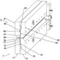
FIG. 4 is a cross-sectional perspective view of one of the air knives themselves;
FIG. 5 is a partial view of the air knife of FIG. 4 showing a groove in accordance with the present invention;
FIG. 6 is a schematic cross-sectional view of another embodiment of a treatment bath and a rinse bath incorporating a liquid removal device of the present invention;
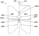
FIG. 7 is a partial view of a liquid removal and isolation air knife included in the embodiment of FIG. 6;
FIG. 8 is a similar view of the air knife in combination with the fluid bearing;
FIG. 9 is a view similar to FIG. 6 of a horizontal arrangement of a wash station including the air knives of the present invention;
FIG. 10 is a view similar to FIG. 4 of a different air knife; and
fig. 11 is a view similar to fig. 8 of a further different air knife.
Referring to the drawings, a web treatment apparatus 1 has two treatment tanks 2, 3, each having respective upper and lower bearing fluid bearings 21, 22; 31. 32 of the mold. During use, the webs 4 are bent around their circumference to pass for treatment with the chemical solution 23 in the bath 2 and washing with water in the bath 3. At the inlet from the basin 2 to/from the basin 3 and at the outlet from the basin 3, respective air knives 5, 6 are arranged. Although oriented differently, they are substantially identical and only one is described in detail. The web 4 passes around a plurality of other fluid bearings 10 which direct it into or out of the pool.
Each air knife consists of four parts, the upstream and downstream parts 71, 72 being fixed together as the lower member 7 and the similar parts 81, 82 being fixed together as the upper member 8. The upstream components 71, 81 have planar engagement surfaces 73, 83; while the downstream components 72, 82 have machined surfaces 74, 84 configured with air supply plenums 75, 85, air supply slots 76, 86, internal air plenums 77, 87 and air knife slots 78, 88. Means, not shown, are provided to supply air to the plenums 75, 85 so that the extended air nozzles are directed away from the slots 78, 88 towards each other. When between the wind knife members, they affect the mesh.
From the slots, the air flows along the top and bottom surfaces 41, 42 of the web. In the absence of the grooves 9, the air flow leaves the air knives in the upstream and downstream directions, flowing out between the opposing surfaces 79, 89 of the knife members, as will be described in accordance with the present invention. In doing so, the air blows off any droplets that tend to enter between the components.
The inventors expect that the effect of the air knife is sufficient when drying the web. However the inventors have experienced the effect of uneven drying in the absence of grooves 9.
The grooves include upstream and downstream, opposite semicircular grooves 91, 92 in the opposite surfaces 79, 89. The inventors believe that they operate as a plenum chamber to fully equalize air pressure and air flow over the outward surfaces 41, 42 of their webs 4.
Furthermore, the opposing surfaces are slightly concave outwardly of the grooves, with a spacing 101 therebetween that is greater than a spacing 102 inwardly of the grooves. Thus making the flow not only uniform but also slow. Again, this is surprising but effective.
Turning now to fig. 6-8, another web processing apparatus has a processing bath 202 having an inlet air bearing 210 on its surface with an array of air nozzles 211, which air nozzles 211 direct the web 204 across it into the processing bath. The pressure of the filtered air supplied to the bearing is slightly above atmospheric pressure. The air may be treated as standard well known CDA air, i.e. clean dry compressed air. It is emitted from the nozzle creating an air bearing layer so that the mesh can pass over the bearing without contacting the bearing.
The cell has respective upper and lower fluid bearings 221, 222. They are supplied with liquid 223 by which the web is treated in a bath like a nozzle (not shown), the supplied liquid being subjected to pressure and generating a bearing membrane to pass the web along a tortuous path around the bearing without touching the bearing.
Vertically away from the treatment basin, the web 204 passes into the liquid of the isolation air knives 206. The arrangement of the upper and lower air knife slits 2061 is different from that of the air knife 6 described above. Above the slit, its opposing member 2062 has opposing grooves 2063 on its opposing surfaces 20641, 20642. The grooves serve to stabilize the flow of CDA air upward so that the cleaning liquid 233 existing above the air knives does not penetrate between the opposing members 2062 of the air knives. Below the slit, the opposing surface is recessed to form a slot 2065. These open downwardly and if any treatment liquid is delivered to the slot, any treatment liquid drawn on the web is blown back by air emanating from the slot and through the narrow air gaps between the un-recessed strips 2066 of the opposing surface 2064 below the slit.
Typical dimensions that the inventors have found to be satisfactory for supplying 0.5 bar of air to the slits when the web is 0.1mm thick are:

it is also practical that the inventors expect a corresponding halving to doubling of the size to be practical, as long as it is practical.
Two cleaning liquid feed bearings 2031 are disposed above and on one side of the air knife 206 and upstream of the cleaning bath 203. A cleaning fluid 233 (typically deionized water) is pumped to the bearings and forms a bearing film thereon. Some of the liquid flows from the web back down the air knife 206, which flows around the edge of the web to begin cleaning the other side of the web.
From the transfer bearing, the web passes to a first portion 2032 of the cleaning bath 203. Where it bypasses another bearing 2034, which is configured with cleaning solution, above the normal depth 2036 of cleaning solution in the sump. The web is thus conveyed up to the composite bearing and air knife 207. It has a bearing cylinder 2071, which is divided into two cleaning liquid passages 20721, 20722 from the inside with a central air passage 2073 therebetween. Each having a bearing nozzle 2074. Above the cylinder 2071, a wind blade opposing member 2075 having a central wind blade slit 2076 and upstream and downstream notches 2077 is arranged.
As the mesh passes over the bearing cylinder and air is supplied to the slots 2076 and central passage, and cleaning liquid is supplied to the passages 20721, 20722, the air flow separates the cleaning liquid of the first portion 2032 and the second portion 2033 of the cleaning bath 203. Any cleaning liquid carried by the mesh to the top of the mesh on the cylinder 2071 is blown back at the upstream slot 2077. Likewise, when the same liquid is pumped to the upstream passages 20721 and ejected through their nozzles, air from the central passage 2073 blows back the liquid to prevent it from passing through the slits 2078.
While the same cleaning fluid may be pumped to the passages 20722, which may also remain separate, in the composite bearing and air knife 207 and indeed in the second portion 2033 of the cleaning bath, improved cleaning. Likewise, air from the central passage tends to blow back any liquid from the second passage 20722, which may tend to flow back through the central air nozzle 2074. Bearing fluid from passage 20722 and its nozzle 2074 enter the second portion 2033 of the sump.
At this pool portion, the mesh passes around another wet bearing 2037 and up to the air knife 208. It should be noted that cleaning occurs at the bearing where the cleaning fluid flows in a hydrodynamic bearing film relative to the web, rather than by immersion in the liquid in the first portion 2032 and the second portion 2033 of the cleaning bath 203.
The air knife 208 has upper and lower slots 2081 similar to the slot 2065. The web thus passes through the air bearing 209 and into a subsequent processing or take-up station (not shown).
Turning to fig. 9, a fluid isolation air knife may be used to travel horizontally with the web or sheet being processed and at the various angles described above. Figure 9 shows pairs of wash stations 301, 302 (as shown in our british patent No 2,459,055) each having upper and lower, upstream and downstream flow paths to define plates 3011, 3012, 3013, 3014 and 3021, 3022, 3023, 3024 with double staggered wash liquor slots 3015, 3025. The mesh 304 passes between the plate and the nozzle. The air knives 305, 306 and 307 are arranged between the upstream and downstream of the washing station.
The air knife 306 between the stations 301, 302 has grooves 3061, 3062 on its opposing members and is chamfered at the upstream and downstream edges 3063. The edge of the cleaning station has a flat plate arranged close to the air knife member so that the cleaning liquid flows over the top of the top plate and remains free running from below the web, so that the web is exposed to the cleaning liquid for as long as possible. The chamfer of the air knife therefore has cleaning fluid between it and the mesh. Nevertheless, the grooves provided from the chamfer are effective to provide uniform air flow from between the opposing members so that liquid does not flow through the chamfer into the air knives.
The air knives 305, 307 have similar grooves on their sides facing the plates of the washing station. On its outside, it has notches (e.g., notches 2065, 2077, 2081). Which is split from the lands between the central air knife slit like the lands between the grooves and the air knife slit, so that the air flow from the slit is split upstream and downstream.
Two further variants are shown in fig. 10 and 11. The air knife 17 of fig. 10 has a three-part structure, as compared with the two-part structure shown in fig. 4. In the description of this variant, the upper part and the lower part are not described separately, since they are practically identical to each other. The outward pieces 171, 172 with the grooves 192 are identical except for mirror images of each other, each having a machined surface 174 with an air supply plenum 175, an air supply groove 176, an inner plenum 177, and a knife slot 78. But these outer parts rest against the planar innermost part 190. Thus, two air knife slits are provided to supply the same air. The innermost and outer members are flush with the slit and the innermost member is planar over the web passage. As long as no air can flow inwardly from the slits, it flows outwardly and is expected to be very close to the flow in the upstream and downstream directions. If the spacing between the slits must be significantly larger than the outer air bearing surface, grooves (or notches) may be provided to prevent contact between the innermost member and the mesh.
Figure 11 shows an arrangement similar to the two slits incorporated into the combined air knife and bearing of figure 8. The center plate 501 functions the same as the innermost member 190. But with a grooved channel surface 502. This is to prevent contact between the mesh and the central plate. Two mirror image exterior members 503, 504, conveniently 3D printed, are formed with a plenum 505, a slit forming portion 506 and an exterior groove 507 to each side of the central panel. In use air is supplied to the plenum to separate the supplied liquid from the outer passages 508, 509 and to configure the bearing operation through the nozzle 510.
Claims (26)
1. A liquid isolation device comprising
An air knife having:
a pair of opposed members having opposed surfaces, each member having at least one slot or linear array of apertures through which air can be blown so as to blow liquid away from the opposed surfaces of the plate, sheet or web passing between the opposed members in the direction of travel;
the method is characterized in that:
the liquid isolating means comprises three channels, one for supplying air to the slit thereof and two for supplying respective liquids to the nozzles upstream and downstream of said opposite member of the slit;
the slits or linear arrays of apertures are arranged at right angles to the opposing surface, so that the air flows upstream and downstream of said opposing surface with respect to the direction of travel;
each opposing surface has:
two faces that oppose respective faces in the other member of the pair of opposing members, wherein one face is upstream of a slot or linear array of apertures in the respective member and the other face is downstream of a slot or linear array of apertures in the respective member; and is
Each opposing face has:
at least one elongated groove or slot upstream or downstream of the respective slot or linear array of apertures with respect to the direction of travel and spaced from the slot or linear array of apertures by a respective face,
this arrangement isolates the liquid at the sides of the air knife during use.
2. The liquid isolation device of claim 1, wherein the grooves or slots are evenly and upstream and downstream spaced by a slot or linear array of apertures in each opposing surface.
3. A liquid isolation apparatus as claimed in claim 1 or 2, wherein each slit or linear array of apertures in opposing members are directed towards each other.
4. Liquid separating device according to claim 1 or 2,
the air knives have a length transverse to the direction of travel and are narrower in the direction of travel relative to the length of the air knives, and
each elongated groove or slot is substantially parallel to a respective slot or linear array of apertures.
5. The fluid isolation device of claim 1, wherein at least one elongate groove is provided and the respective opposing surface extends across the groove substantially flush with itself at the aperture of the respective slot or linear array.
6. Liquid isolation device according to claim 1 or 2, wherein the at least one elongated groove is arranged such that the upstream and/or downstream groove is opposite the planar counterpart.
7. Liquid isolation device according to claim 1 or 2, wherein at least one elongated groove is configured as a single pair upstream or a single pair downstream of the slit or aperture.
8. The fluid isolation device of claim 1, wherein the at least one elongated groove comprises an elongated opposing pair of grooves upstream and downstream of the slit or aperture.
9. The fluid isolation device of claim 1, wherein the at least one elongated groove comprises a plurality of pairs of opposing pairs of grooves upstream and downstream of the slit or aperture.
10. A fluid isolation device as claimed in claim 8 or 9, wherein opposed pairs of recesses are aligned opposite each other.
11. A liquid isolation apparatus as claimed in claim 8 or 9, wherein the opposed pairs of grooves are staggered relative to each other.
12. A liquid barrier apparatus according to claim 1 wherein the separation of the opposed surfaces is greater on the outside of each groove than on the inside thereof, so that between each groove and the line of slits or apertures the air flow is slower on the outside than on the inside using one or more grooves.
13. The fluid isolation device of claim 1, wherein at least one elongated slot is provided, each slot extending outwardly from a respective slot or linear array of apertures to an edge of a distal slot opposing member.
14. A liquid isolation apparatus according to claim 13, wherein each notch is of constant depth or of different depth across its width.
15. The fluid isolation device of claim 13, wherein the width of the slot is greater than the width of the opposing surface between the slot and each slot or linear array of apertures.
16. A liquid barrier according to claim 1 wherein there are grooves or notches on one opposing surface of one opposing member and the mirror image of the same grooves or notches on the opposing surface of the other opposing member so that the mesh acts equally on both sides.
17. The fluid isolation device of claim 1, wherein the opposing surfaces are chamfered at distal edges thereof.
18. The fluid isolation device of claim 1, wherein the opposing member is substantially planar.
19. The fluid isolation device of claim 1, wherein one of the opposing members is curved and not flush with either of the groove and the notch.
20. A liquid isolation apparatus as claimed in claim 1, wherein one of the opposing members is curved and flush with the groove on either side of the slit.
21. A liquid isolation means as claimed in claim 19 or 20, wherein one opposing member is curved and is a bearing member within the curvature of the web over which it passes.
22. A liquid isolation apparatus as claimed in claim 19 or 20, wherein the other opposing member is complementarily curved.
23. The fluid isolation device of claim 1, wherein each of the opposing members is comprised of two pieces, complementarily machined on the engagement surface to configure its slot, and secured together to configure one of the opposing members.
24. A liquid isolation apparatus as claimed in claim 1, wherein one or each opposing surface has at least two lines of slits or apertures, and the one or more grooves/notches are provided outwardly of the at least two lines of slits/apertures.
25. The fluid isolation device of claim 24, wherein each of the opposing members is comprised of three pieces that are complementarily machined on an engagement surface and secured together to configure one of the opposing members,
a central part with a plane or groove and two parts with a groove or notch, machining at the junction of the central part with a plane or groove and the two parts with a groove or notch to configure one said slit between the central part and one part with a groove or notch and another said slit between the central part and the other part with a groove or notch, and
the central member is flush with the other grooved or notched member between the slits.
26. A fluid isolation device of claim 1, wherein the counter member is comprised of one piece or three pieces that are complementarily machined on the engagement surface and secured together to configure one of the counter members,
when there are three parts, between at least one linear array of apertures in each opposing member and two outer regions with grooves or notches, a central part of the three parts or a central strip of one of the three parts with a plane or a groove is provided, and
the central strip is flush with the outer region.
Applications Claiming Priority (5)
| Application Number | Priority Date | Filing Date | Title |
|---|---|---|---|
| GB1519445.9 | 2015-11-03 | ||
| GBGB1519445.9A GB201519445D0 (en) | 2015-11-03 | 2015-11-03 | Liquid removal |
| GB1600887.2 | 2016-01-18 | ||
| GBGB1600887.2A GB201600887D0 (en) | 2016-01-18 | 2016-01-18 | Liquid removal |
| PCT/GB2016/053395 WO2017077291A1 (en) | 2015-11-03 | 2016-11-02 | Liquid removal |
Publications (2)
| Publication Number | Publication Date |
|---|---|
| CN108449936A CN108449936A (en) | 2018-08-24 |
| CN108449936B true CN108449936B (en) | 2022-03-11 |
Family
ID=57570083
Family Applications (1)
| Application Number | Title | Priority Date | Filing Date |
|---|---|---|---|
| CN201680076531.6A Active CN108449936B (en) | 2015-11-03 | 2016-11-02 | Liquid removing device |
Country Status (5)
| Country | Link |
|---|---|
| JP (1) | JP6984812B2 (en) |
| KR (1) | KR20180078278A (en) |
| CN (1) | CN108449936B (en) |
| TW (1) | TWI760316B (en) |
| WO (1) | WO2017077291A1 (en) |
Families Citing this family (3)
| Publication number | Priority date | Publication date | Assignee | Title |
|---|---|---|---|---|
| CN114877666A (en) * | 2022-02-25 | 2022-08-09 | 南京华易泰电子科技有限公司 | Double-slit air knife structure suitable for panel drying and processing technology thereof |
| CN114713563B (en) * | 2022-03-01 | 2023-03-07 | 长沙振安机电设备有限公司 | Motor cleaning device |
| CN115682649B (en) * | 2022-10-24 | 2023-08-08 | 深圳市行知行机器人技术有限公司 | Wiping mechanism and cleaning device |
Citations (5)
| Publication number | Priority date | Publication date | Assignee | Title |
|---|---|---|---|---|
| CN1993188A (en) * | 2004-08-05 | 2007-07-04 | 株式会社神户制钢所 | Deposit removing device |
| CN103851887A (en) * | 2012-12-07 | 2014-06-11 | 深南电路有限公司 | PCB (printed circuit board) drying machine |
| CN104043613A (en) * | 2014-06-19 | 2014-09-17 | 张家港市超声电气有限公司 | Wind cutting blowing-dry device |
| CN104117504A (en) * | 2014-06-26 | 2014-10-29 | 苏州一合光学有限公司 | Air knife device of glass air knife cleaning machine |
| CN104990383A (en) * | 2015-07-31 | 2015-10-21 | 北京七星华创电子股份有限公司 | On-line air knife drying device |
Family Cites Families (21)
| Publication number | Priority date | Publication date | Assignee | Title |
|---|---|---|---|---|
| DE241981C (en) * | 1910-05-24 | |||
| US2423768A (en) * | 1943-01-13 | 1947-07-08 | Warren S D Co | Apparatus for coating flexible webs |
| US3002700A (en) * | 1958-07-26 | 1961-10-03 | Mohring Gustav | Nozzle on heat-treatment machines for textile fabrics and the like |
| JPS5425066A (en) * | 1977-07-28 | 1979-02-24 | Chugai Ro Kogyo Kaisha Ltd | Nonncontact type shape correcting and holding method of beltlike material and its device |
| US4551926A (en) * | 1984-05-23 | 1985-11-12 | C. Keller Gmbh U. Co. Kg Maschinenfabrik | Nozzle box for heat treatment of veneering |
| US4848633A (en) * | 1986-02-28 | 1989-07-18 | Thermo Electron Web Systems, Inc. | Non-contact web turning and drying apparatus |
| DE59202907D1 (en) * | 1991-05-17 | 1995-08-24 | Sundwiger Eisen Maschinen | Device for removing liquid from the surface of a moving belt. |
| JP2528669Y2 (en) * | 1991-08-19 | 1997-03-12 | 三菱重工業株式会社 | Plenum duct for tenter oven |
| JP2552595B2 (en) * | 1991-09-17 | 1996-11-13 | 株式会社東京機械製作所 | Damping method and damping device for running web |
| CH687957A5 (en) * | 1994-09-06 | 1997-04-15 | Schneider Consulting & Dev | Dust=removal method from surface of moving material band |
| KR100469133B1 (en) * | 1999-06-24 | 2005-01-29 | 스미도모쥬기가이고교 가부시키가이샤 | Method and device for washing by fluid spraying |
| JP4352194B2 (en) * | 2000-04-04 | 2009-10-28 | 株式会社日立ハイテクノロジーズ | Substrate drying apparatus and substrate drying method |
| JP2001335205A (en) * | 2000-05-24 | 2001-12-04 | Mitsubishi Heavy Ind Ltd | Double-faced floater-type dryer, double-faced floater- type cooler, and double-faced floater-type humidifier |
| TWI236944B (en) * | 2001-12-17 | 2005-08-01 | Tokyo Electron Ltd | Film removal method and apparatus, and substrate processing system |
| GB2459055B (en) | 2007-01-11 | 2012-05-23 | Peter Philip Andrew Lymn | Liquid treatment apparatus |
| KR20080090070A (en) * | 2007-04-04 | 2008-10-08 | 삼성전자주식회사 | Air knife and apparatus drying substrates having the same |
| KR101020779B1 (en) * | 2008-07-31 | 2011-03-09 | 주식회사 디엠에스 | air knife apparatus |
| NL2006389A (en) * | 2010-04-15 | 2011-10-18 | Asml Netherlands Bv | Fluid handling structure, lithographic apparatus and a device manufacturing method. |
| EP2381310B1 (en) * | 2010-04-22 | 2015-05-06 | ASML Netherlands BV | Fluid handling structure and lithographic apparatus |
| GB2500564A (en) * | 2012-01-26 | 2013-10-02 | Peter Philip Andrew Lymn | Web processing machine |
| JP2013256384A (en) * | 2012-06-14 | 2013-12-26 | Japan Steel Works Ltd:The | Air jet nozzle |
-
2016
- 2016-11-02 WO PCT/GB2016/053395 patent/WO2017077291A1/en active Application Filing
- 2016-11-02 JP JP2018541576A patent/JP6984812B2/en active Active
- 2016-11-02 KR KR1020187015107A patent/KR20180078278A/en not_active Application Discontinuation
- 2016-11-02 CN CN201680076531.6A patent/CN108449936B/en active Active
- 2016-11-03 TW TW105135698A patent/TWI760316B/en active
Patent Citations (5)
| Publication number | Priority date | Publication date | Assignee | Title |
|---|---|---|---|---|
| CN1993188A (en) * | 2004-08-05 | 2007-07-04 | 株式会社神户制钢所 | Deposit removing device |
| CN103851887A (en) * | 2012-12-07 | 2014-06-11 | 深南电路有限公司 | PCB (printed circuit board) drying machine |
| CN104043613A (en) * | 2014-06-19 | 2014-09-17 | 张家港市超声电气有限公司 | Wind cutting blowing-dry device |
| CN104117504A (en) * | 2014-06-26 | 2014-10-29 | 苏州一合光学有限公司 | Air knife device of glass air knife cleaning machine |
| CN104990383A (en) * | 2015-07-31 | 2015-10-21 | 北京七星华创电子股份有限公司 | On-line air knife drying device |
Also Published As
| Publication number | Publication date |
|---|---|
| TWI760316B (en) | 2022-04-11 |
| WO2017077291A1 (en) | 2017-05-11 |
| TW201728242A (en) | 2017-08-01 |
| JP6984812B2 (en) | 2021-12-22 |
| KR20180078278A (en) | 2018-07-09 |
| CN108449936A (en) | 2018-08-24 |
| JP2018535831A (en) | 2018-12-06 |
Similar Documents
| Publication | Publication Date | Title |
|---|---|---|
| CN108449936B (en) | Liquid removing device | |
| KR101284197B1 (en) | Method and assembly for treating a planar material to be treated and device for removing or holding off treatment liquid | |
| KR890014146A (en) | How to operate the membrane separation system | |
| KR20110126506A (en) | Membrane module | |
| JPH0448872Y2 (en) | ||
| ITUA20164038A1 (en) | EQUIPMENT FOR FABRIC IMPREGNATION | |
| JP7273788B2 (en) | DRYING APPARATUS AND METHOD FOR DRYING A SUBSTRATE | |
| JP2017008346A (en) | Substrate conveyance apparatus and holding part | |
| KR101731751B1 (en) | Device and method for the wet-chemical treatment of flat material to be treated | |
| JP4346967B2 (en) | Resist stripping device | |
| KR102497944B1 (en) | Manufacturing method of glass plate and manufacturing apparatus therefor | |
| JP5935982B2 (en) | Immersion membrane separator | |
| EP0564598B1 (en) | Photographic developing apparatus | |
| US5239327A (en) | Processor for light sensitive material | |
| US9206514B2 (en) | Liquid treatment apparatus | |
| TW201515974A (en) | Method and apparatus for a wet-chemical or electrochemical treatment | |
| CN217345862U (en) | Immersion type water jet cutting processing equipment for circuit board | |
| TW201922365A (en) | Method for manufacturing glass plate | |
| JPWO2022224886A5 (en) | ||
| JP5665302B2 (en) | Steel strip electroplating equipment | |
| KR102090528B1 (en) | Flexible substrate cleaning apparatus | |
| CN107572832A (en) | Wet processing equipment | |
| CN116728517A (en) | Immersion type water jet knife treatment equipment for circuit board | |
| JP3154455B2 (en) | Photosensitive material processing equipment | |
| SU1536349A2 (en) | Apparatus for chemical photographic processing of web and format photographic materials |
Legal Events
| Date | Code | Title | Description |
|---|---|---|---|
| PB01 | Publication | ||
| PB01 | Publication | ||
| SE01 | Entry into force of request for substantive examination | ||
| SE01 | Entry into force of request for substantive examination | ||
| GR01 | Patent grant | ||
| GR01 | Patent grant |