CN108431688B - Lens barrel and camera body - Google Patents
Lens barrel and camera body Download PDFInfo
- Publication number
- CN108431688B CN108431688B CN201680075144.0A CN201680075144A CN108431688B CN 108431688 B CN108431688 B CN 108431688B CN 201680075144 A CN201680075144 A CN 201680075144A CN 108431688 B CN108431688 B CN 108431688B
- Authority
- CN
- China
- Prior art keywords
- cover
- lens barrel
- lens
- range
- camera body
- Prior art date
- Legal status (The legal status is an assumption and is not a legal conclusion. Google has not performed a legal analysis and makes no representation as to the accuracy of the status listed.)
- Active
Links
Images


Classifications
-
- G—PHYSICS
- G02—OPTICS
- G02B—OPTICAL ELEMENTS, SYSTEMS OR APPARATUS
- G02B7/00—Mountings, adjusting means, or light-tight connections, for optical elements
- G02B7/02—Mountings, adjusting means, or light-tight connections, for optical elements for lenses
- G02B7/021—Mountings, adjusting means, or light-tight connections, for optical elements for lenses for more than one lens
-
- G—PHYSICS
- G03—PHOTOGRAPHY; CINEMATOGRAPHY; ANALOGOUS TECHNIQUES USING WAVES OTHER THAN OPTICAL WAVES; ELECTROGRAPHY; HOLOGRAPHY
- G03B—APPARATUS OR ARRANGEMENTS FOR TAKING PHOTOGRAPHS OR FOR PROJECTING OR VIEWING THEM; APPARATUS OR ARRANGEMENTS EMPLOYING ANALOGOUS TECHNIQUES USING WAVES OTHER THAN OPTICAL WAVES; ACCESSORIES THEREFOR
- G03B5/00—Adjustment of optical system relative to image or object surface other than for focusing
-
- G—PHYSICS
- G02—OPTICS
- G02B—OPTICAL ELEMENTS, SYSTEMS OR APPARATUS
- G02B7/00—Mountings, adjusting means, or light-tight connections, for optical elements
- G02B7/02—Mountings, adjusting means, or light-tight connections, for optical elements for lenses
- G02B7/14—Mountings, adjusting means, or light-tight connections, for optical elements for lenses adapted to interchange lenses
- G02B7/16—Rotatable turrets
-
- G—PHYSICS
- G02—OPTICS
- G02B—OPTICAL ELEMENTS, SYSTEMS OR APPARATUS
- G02B27/00—Optical systems or apparatus not provided for by any of the groups G02B1/00 - G02B26/00, G02B30/00
- G02B27/64—Imaging systems using optical elements for stabilisation of the lateral and angular position of the image
- G02B27/646—Imaging systems using optical elements for stabilisation of the lateral and angular position of the image compensating for small deviations, e.g. due to vibration or shake
-
- G—PHYSICS
- G02—OPTICS
- G02B—OPTICAL ELEMENTS, SYSTEMS OR APPARATUS
- G02B7/00—Mountings, adjusting means, or light-tight connections, for optical elements
- G02B7/02—Mountings, adjusting means, or light-tight connections, for optical elements for lenses
-
- G—PHYSICS
- G02—OPTICS
- G02B—OPTICAL ELEMENTS, SYSTEMS OR APPARATUS
- G02B7/00—Mountings, adjusting means, or light-tight connections, for optical elements
- G02B7/02—Mountings, adjusting means, or light-tight connections, for optical elements for lenses
- G02B7/04—Mountings, adjusting means, or light-tight connections, for optical elements for lenses with mechanism for focusing or varying magnification
- G02B7/10—Mountings, adjusting means, or light-tight connections, for optical elements for lenses with mechanism for focusing or varying magnification by relative axial movement of several lenses, e.g. of varifocal objective lens
- G02B7/102—Mountings, adjusting means, or light-tight connections, for optical elements for lenses with mechanism for focusing or varying magnification by relative axial movement of several lenses, e.g. of varifocal objective lens controlled by a microcomputer
-
- G—PHYSICS
- G03—PHOTOGRAPHY; CINEMATOGRAPHY; ANALOGOUS TECHNIQUES USING WAVES OTHER THAN OPTICAL WAVES; ELECTROGRAPHY; HOLOGRAPHY
- G03B—APPARATUS OR ARRANGEMENTS FOR TAKING PHOTOGRAPHS OR FOR PROJECTING OR VIEWING THEM; APPARATUS OR ARRANGEMENTS EMPLOYING ANALOGOUS TECHNIQUES USING WAVES OTHER THAN OPTICAL WAVES; ACCESSORIES THEREFOR
- G03B17/00—Details of cameras or camera bodies; Accessories therefor
- G03B17/02—Bodies
- G03B17/12—Bodies with means for supporting objectives, supplementary lenses, filters, masks, or turrets
- G03B17/14—Bodies with means for supporting objectives, supplementary lenses, filters, masks, or turrets interchangeably
-
- G—PHYSICS
- G03—PHOTOGRAPHY; CINEMATOGRAPHY; ANALOGOUS TECHNIQUES USING WAVES OTHER THAN OPTICAL WAVES; ELECTROGRAPHY; HOLOGRAPHY
- G03B—APPARATUS OR ARRANGEMENTS FOR TAKING PHOTOGRAPHS OR FOR PROJECTING OR VIEWING THEM; APPARATUS OR ARRANGEMENTS EMPLOYING ANALOGOUS TECHNIQUES USING WAVES OTHER THAN OPTICAL WAVES; ACCESSORIES THEREFOR
- G03B17/00—Details of cameras or camera bodies; Accessories therefor
- G03B17/56—Accessories
- G03B17/565—Optical accessories, e.g. converters for close-up photography, tele-convertors, wide-angle convertors
-
- H—ELECTRICITY
- H04—ELECTRIC COMMUNICATION TECHNIQUE
- H04N—PICTORIAL COMMUNICATION, e.g. TELEVISION
- H04N23/00—Cameras or camera modules comprising electronic image sensors; Control thereof
- H04N23/50—Constructional details
- H04N23/55—Optical parts specially adapted for electronic image sensors; Mounting thereof
-
- H—ELECTRICITY
- H04—ELECTRIC COMMUNICATION TECHNIQUE
- H04N—PICTORIAL COMMUNICATION, e.g. TELEVISION
- H04N23/00—Cameras or camera modules comprising electronic image sensors; Control thereof
- H04N23/60—Control of cameras or camera modules
- H04N23/68—Control of cameras or camera modules for stable pick-up of the scene, e.g. compensating for camera body vibrations
- H04N23/682—Vibration or motion blur correction
- H04N23/685—Vibration or motion blur correction performed by mechanical compensation
- H04N23/687—Vibration or motion blur correction performed by mechanical compensation by shifting the lens or sensor position
-
- G—PHYSICS
- G03—PHOTOGRAPHY; CINEMATOGRAPHY; ANALOGOUS TECHNIQUES USING WAVES OTHER THAN OPTICAL WAVES; ELECTROGRAPHY; HOLOGRAPHY
- G03B—APPARATUS OR ARRANGEMENTS FOR TAKING PHOTOGRAPHS OR FOR PROJECTING OR VIEWING THEM; APPARATUS OR ARRANGEMENTS EMPLOYING ANALOGOUS TECHNIQUES USING WAVES OTHER THAN OPTICAL WAVES; ACCESSORIES THEREFOR
- G03B2205/00—Adjustment of optical system relative to image or object surface other than for focusing
- G03B2205/0007—Movement of one or more optical elements for control of motion blur
-
- G—PHYSICS
- G03—PHOTOGRAPHY; CINEMATOGRAPHY; ANALOGOUS TECHNIQUES USING WAVES OTHER THAN OPTICAL WAVES; ELECTROGRAPHY; HOLOGRAPHY
- G03B—APPARATUS OR ARRANGEMENTS FOR TAKING PHOTOGRAPHS OR FOR PROJECTING OR VIEWING THEM; APPARATUS OR ARRANGEMENTS EMPLOYING ANALOGOUS TECHNIQUES USING WAVES OTHER THAN OPTICAL WAVES; ACCESSORIES THEREFOR
- G03B2206/00—Systems for exchange of information between different pieces of apparatus, e.g. for exchanging trimming information, for photo finishing
-
- G—PHYSICS
- G03—PHOTOGRAPHY; CINEMATOGRAPHY; ANALOGOUS TECHNIQUES USING WAVES OTHER THAN OPTICAL WAVES; ELECTROGRAPHY; HOLOGRAPHY
- G03B—APPARATUS OR ARRANGEMENTS FOR TAKING PHOTOGRAPHS OR FOR PROJECTING OR VIEWING THEM; APPARATUS OR ARRANGEMENTS EMPLOYING ANALOGOUS TECHNIQUES USING WAVES OTHER THAN OPTICAL WAVES; ACCESSORIES THEREFOR
- G03B2217/00—Details of cameras or camera bodies; Accessories therefor
- G03B2217/005—Blur detection
Abstract
The invention provides a lens barrel which can correct large shake in a lens barrel that can be assembled with and disassembled from an image pickup part. A lens barrel (1) of the present invention is a lens barrel (1) having a mounting portion (100) that is attachable to and detachable from an imaging portion (101), and has an imaging optical system (L) that forms an object image on the imaging portion (101), a support portion (40) that supports at least a part of the imaging optical system (L), and a fixing portion (50) that is disposed outside the support portion (40) and fixed to the mounting portion (100), wherein the support portion (40) is capable of relative rotational movement with respect to the fixing portion (50) about 2 or more axes that are substantially orthogonal to an optical axis of the imaging optical system (L).
Description
Technical Field
The present invention relates to a lens barrel and a camera body.
Background
In order to correct a wide range of shake correction angles in an imaging apparatus capable of moving picture shooting, there has been a conventional shake correction mechanism including 2 driving portions each having a support shaft perpendicular to an optical axis, the driving portions being configured to allow a lens barrel integrated with an imaging portion to swing with respect to a frame of the imaging apparatus (see patent document 1).
However, the lens barrel of patent document 1 is integrated with the image pickup unit, and cannot cope with a lens barrel that is detachable from the image pickup unit.
[ Prior Art document ]
[ patent document ]
Patent document 1: japanese patent laid-open publication No. 2013-140285
Disclosure of Invention
One embodiment of the present invention is a camera body to which a lens barrel is attachable and detachable, including: a 1 st cover body having a 1 st coupling portion coupled to a 1 st barrel of the lens barrel; a 2 nd cover body having a 2 nd coupling part coupled to a 2 nd barrel of the lens barrel and an image pickup element; and a switching unit that switches a movable range of the 2 nd cover with respect to the 1 st cover between a 1 st range state and a 2 nd range state.
Another embodiment of the present invention is a lens barrel having a mounting portion that is attachable to and detachable from an image pickup portion, the lens barrel including: an imaging optical system that images a subject image on an imaging section; a support portion that supports at least a part of the imaging optical system; and a fixing portion disposed outside the support portion and fixed to the mounting portion; the support portion is capable of relative rotational movement with respect to the fixed portion around 2 or more axes substantially orthogonal to the optical axis of the imaging optical system.
Another embodiment of the present invention is a camera body including: an interior fitting portion that is attachable to and detachable from at least a part of a lens barrel having an imaging optical system; an imaging section that images a subject image imaged by the imaging optical system; and a body fixing portion disposed outside the image pickup portion; the imaging unit is movable together with the interior assembly unit relative to the body fixing unit about 2 or more axes substantially orthogonal to the optical axis of the imaging optical system.
The above-described structure may be suitably modified, and at least a part of the structure may be replaced with another structure.
Drawings
Fig. 1 is a system configuration diagram of a camera system 3 including a lens barrel 1 and a camera body 2 according to an embodiment.
Fig. 2 is an exploded view of the lens barrel 1.
Fig. 3 is a sectional view of the lens barrel 1 along the optical axis Z in a collapsed state, (a) is an X-Z sectional view (a sectional view through the pitch axis P), and (b) is a Y-Z sectional view (a sectional view through the yaw axis Y).
Fig. 4 is a sectional view of the lens barrel 1 along the optical axis Z in the extended and retracted state, (a) is an X-Z sectional view (a sectional view through the pitch axis P), and (b) is a Y-Z sectional view (a sectional view through the yaw axis Y).
Fig. 5 is a sectional view of the lens barrel 1, (a) is an X-Y sectional view at a position passing through the pitch axis P and the yaw axis Y, and (b) is an X-Y sectional view at a position passing through the button 70.
Fig. 6 is a perspective view of the 2 nd cover 10, showing a part of the pitch driving part 20.
Fig. 7 is a perspective view of the 2 nd cover 10, showing a part of the pitch driving part 20 and the yaw driving part 60.
Fig. 8 is a perspective view of the first cover 30, showing a part of the yaw driving portion 60.
Fig. 9 is an enlarged view of the yaw driving unit 60, where (a) shows a state in which the interval between the object side yaw driving coil 61A and the body side yaw driving coil 61B in the yaw driving unit 60 is extended, and (B) shows a state in which the interval between the object side yaw driving coil 61A and the body side yaw driving coil 61B is shortened.
Fig. 10 is an exploded view of the yaw driving portion 60 as viewed obliquely from the outside.
Fig. 11 is an exploded view of the yaw drive unit 60 as viewed obliquely from the inside.
Fig. 12 is a partial sectional view showing a button 70 portion of the lens barrel 1, (a) shows an extended state of the lens barrel 1, and (b) shows a retracted state of the lens barrel 1.
Fig. 13 is a diagram showing a positional relationship between the push button 70 and the long push button guide hole 54 of the fixed tube 50, where (a) is a diagram showing a position of the push button 70 when the sliding portion 62 extends from the inner side of the fixed tube 50, (b) is a diagram showing a position of the push button 70 when the sliding portion 62 extends from the outer side of the fixed tube 50, (c) is a diagram showing a position of the push button 70 when the sliding portion 62 shortens from the inner side of the fixed tube 50, and (d) is a diagram showing a position of the push button 70 when the sliding portion 62 shortens from the outer side of the fixed tube 50.
Fig. 14 is a perspective view of the 3 rd cover 80.
Fig. 15 is a perspective view of the fixed barrel 50.
Fig. 16 is a partial sectional view of the lens barrel 1.
Fig. 17 is a perspective view showing the 1 st cover 30 and the spherical coil 58 provided in the fixed cylinder 50.
Fig. 18 is a diagram illustrating driving in the yaw direction.
Fig. 19 is a diagram showing a modification in which the supporting portion 40 is completely fixed to the fixed cylinder 50 on the lens barrel 1 side.
Fig. 20 is a view illustrating a locked state of the support portion 40 with respect to the fixed cylinder 50, in which (a) shows the locked state and (b) shows the unlocked state.
Fig. 21(a) and (b) are diagrams illustrating the arrangement of the FPC connected to the pitch drive unit 20, the yaw drive unit 60, and the yaw assist drive unit 90.
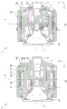
Fig. 22 is a view showing the inside of the camera body 2 of the present embodiment, in which (a) is a side view, (b) is a front view, and (c) is a sectional view. (b) Is a cross-sectional view of Z1-Z1 of (c).
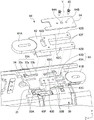
Fig. 23 is an exploded perspective view of the peripheral portion of the camera body 2 of fig. 22.
Fig. 24 is a partially exploded perspective view of fig. 23.
Fig. 25 shows the case 160 of the fuselage outer shell and the 1 st retainer 112 of the fuselage inner shell 110, (a) shows a state in which the fuselage inner shell 110 and the fuselage outer shell 150 are locked, and (b) shows a state in which the locking of the fuselage inner shell 110 and the fuselage outer shell 150 is released.
Fig. 26 is a peripheral view of a lens-side attachment of the lens barrel 1, where (a) is a view seen from the camera body 2 side and (b) is a view seen obliquely from the camera body 2 side.
Fig. 27 shows the locking levers 153 and 154, where (a) is positioned in the housing 160, and (b) is a state where the housing 160 is omitted.
Fig. 28 is a diagram showing the relationship between the image pickup device movable block 111 and the release plate 163, where (a) shows a state where the image pickup device movable block 111 is positioned in the housing 160 at the release plate initial position, and (b) shows a state where the image pickup device movable block is released from the housing 160 at the release plate release position.
Fig. 29 is a schematic view of the locking levers 153 and 154.
Fig. 30 is a system configuration diagram of a modified camera system 3 ' including a lens barrel 1 ' and a camera body 2 '.
Fig. 31 is a diagram showing embodiment 2 of the camera body 2.
Fig. 32 is a diagram showing an unlocked state of the camera body 2 according to embodiment 3.
Fig. 33 is a diagram showing a locked state of the camera body 2 according to embodiment 3.
Detailed Description
Hereinafter, embodiments of the present invention will be described with reference to the drawings and the like.
In the drawings shown below, an XYZ rectangular coordinate system is provided for convenience, ease of explanation, and understanding.
In this coordinate system, a direction in which the camera body 2 is oriented rightward from the viewpoint of the photographer (hereinafter, referred to as a "normal position") when the photographer photographs a horizontally long image with the optical axis horizontal when the lens barrel 1 is attached to the camera body 2 is set to be a + X direction.
In addition, a direction toward the upper side in the normal position is set as a + Y direction.
The direction toward the object at the normal position is defined as the + Z direction (optical axis direction).
In the following description, terms such as the pitch axis P and the yaw axis Y are used as necessary for easy understanding. In the embodiment, the pitch axis P is in the same direction as the X axis, and the yaw axis Y is in the same direction as the Y axis and is orthogonal to each other. The term "orthogonal" includes not only a strict 90 degrees but also a range slightly deviated from 90 degrees due to manufacturing error and assembly error.
The rotation about the pitch axis P is referred to as pitch, the rotation about the yaw axis Y is referred to as yaw, the direction of pitch is referred to as the pitch direction, and the direction of yaw is referred to as the yaw direction.
(embodiment 1)
Fig. 1 is a system configuration diagram of a camera system 3 including a lens barrel 1 and a camera body 2 according to an embodiment.
Fig. 2 is an exploded view of the lens barrel 1.
Fig. 3 is a sectional view of the lens barrel 1 along the optical axis Z in a collapsed state, (a) is an X-Z sectional view (a sectional view through the pitch axis P), and (b) is a Y-Z sectional view (a sectional view through the yaw axis Y).
Fig. 4 is a sectional view of the lens barrel 1 along the optical axis Z in the extended and retracted state, (a) is an X-Z sectional view (a sectional view through the pitch axis P), and (b) is a Y-Z sectional view (a sectional view through the yaw axis Y).
Fig. 5(a) is an X-Y sectional view of the lens barrel 1 at a position passing through the pitch axis P and the yaw axis Y, and (b) is an X-Y sectional view of the lens barrel 1 at a position passing through a below-described pressing slide pin 62E.
(lens barrel 1)
The lens barrel 1 of the present embodiment is attachable to and detachable from the camera body 2. In addition, the lens barrel 1 is retractable between a retracted state (non-shooting state, accommodated state, retracted state) and a retracted state (shooting state).
As shown in the system configuration diagram of fig. 1, the lens barrel 1 includes a 2 nd cover 10 (lens inner case) that holds a lens group L as an imaging optical system therein, a 1 st cover 30 disposed on the outer periphery of the 2 nd cover 10, a fixed cylinder 50 (lens outer case) disposed on the outer periphery of the 1 st cover 30, and the like. Collectively, the 2 nd cover 10 and the 1 st cover 30 are referred to as a support portion 40.
In the lens barrel 1 of the present embodiment, the 2 nd cover body 10 is rotatable in the pitch direction about the pitch axis P with respect to the 1 st cover body 30; the 1 st cover 30 is rotatable in the deflecting direction about the deflecting axis Y with respect to the fixed barrel 50.
As shown in fig. 2, lens barrel 1 further includes a 3 rd cover body 80 covering the distal end of 2 nd cover body 10, and an outer tube 85 covering the entire outer periphery of lens barrel 1.
When the entire outer shape of the lens barrel 1 is a cylindrical shape, each cover body is also preferably a cylindrical shape. However, as in the case of the 1 st cover 30 of the present embodiment, a flat portion may be provided on the inner circumferential surface or the outer circumferential surface for the purpose of arranging other components. The cylindrical shape of each cover may be deformed to form a flat portion, a notch, a portion with a varying thickness, or the like as appropriate.
(No. 2 shield 10)
As shown in fig. 1, the 2 nd cover body 10 of the lens barrel 1 includes a lens group L, a translational (shift) direction vibration isolation system 4, a 1 st shake detection unit 5, a 2 nd shake detection unit 6, a vibration isolation optical system position detection unit 7, a lens control unit 8, and a lens-side interior fitting 9.
Further, the 2 nd cover 10 has a part of the pitch drive unit 20 that drives the 2 nd cover 10 in the pitch direction with respect to the 1 st cover 30.
The 1 st shake detection unit 5 is preferably disposed on the pitch axis P.
The lens group L includes an anti-vibration optical system LB, which is an imaging optical system for imaging a subject image on the image pickup device 101 disposed in the camera body 2.
The 1 st shake detection unit 5 is a gyro sensor or the like, and detects the pitch and yaw of the camera system 3.
The 2 nd shake detection unit 6 is a gyro sensor or the like, and detects a shake in the translational direction, which is the movement in the X-axis direction and the Y-axis direction of the camera system 3.
The panning direction vibration isolation system 4 (details are omitted) includes a vibration isolation optical system LB that moves in the XY directions (panning directions), a movable frame 41 that holds the vibration isolation optical system LB, a vibration isolation optical system position detection unit 7 that detects the position of the vibration isolation optical system LB, and a panning direction driving voice coil motor (panning direction driving VCM42) that drives the movable frame 41 in the panning directions. Hereinafter, the voice coil motor is simply referred to as VCM.
The lens control section 8 controls the pan direction drive VCM42 based on the signal input from the 2 nd shake detection section 6. By driving the VCM42 in the panning direction, the vibration-proof optical system LB is driven in a direction to cancel image shake of the subject image due to hand shake of the photographer or the like, and image shake in the panning direction is corrected.
The lens-side interior fitting 9 is provided at the body-side end of the 2 nd cover 10, and includes a mechanical fitting 91, a communication contact 92, and a power receiving contact 93.
The 2 nd cover 10 has a part of the pitch driving section 20 driven in the pitch direction. Fig. 6 is a perspective view of the 2 nd cover 10, showing a part of the pitch driving part 20. Fig. 7 is a perspective view of the 2 nd cover 10, showing a part of the pitch drive unit 20 and the yaw drive unit 60.
(Pitch drive unit 20)
A tilt driving unit 20 for driving the 2 nd cover 10 in a tilt direction is provided on the outer periphery of the 2 nd cover 10.
As shown in fig. 6, the pitch drive unit 20 includes a pitch drive coil holding unit 21 fixed to the 2 nd cover 10, and 2 pitch drive coils 22A and 22B attached to the pitch drive coil holding unit 21.
As shown in fig. 7, the optical axis direction object side tilt driving magnet and yoke 23A and the optical axis direction body side tilt driving magnet and yoke 23B are attached to the 1 st cover 30 (not shown in fig. 7).
Fig. 8 to be described later shows a state in which the pitch drive magnet and the yokes 23A and 23B are attached to the 1 st cover 30.
The pitch drive coils 22A and 22B are elliptical rings and are attached to the subject side and the body side of the pitch drive coil holding unit 21 so that the major axes thereof extend in the optical axis Z direction.
A pitch bearing 25 (fig. 6) into which a pitch shaft member 24 (fig. 7) is rotatably inserted is provided at the center of the pitch drive coil holding portion 21. By inserting the pitch shaft member 24 into the pitch bearing 25, the 2 nd cover 10 can be relatively rotated with respect to the 1 st cover 30 about the pitch axis P.
In the pitch drive coil holding unit 21, a ball receiving metal plate 26 is provided between the pitch bearing 25 and the pitch drive coil 22A on the object side, and between the pitch bearing 25 and the pitch drive coil 22B on the body side.
The balls 27 shown in fig. 3(a) and 4(a) are disposed on the ball receiving sheet metal 26. By disposing ball 27 between first cover 30 and second cover 10, second cover 10 can smoothly rotate relative to first cover 30 about pitch axis P.
As shown in fig. 3, the pitch shaft member 24 passes through the 1 st cover bearing 37 of the 1 st cover 30 from the outside of the 1 st cover 30 and is inserted into the pitch bearing 25 of the 2 nd cover 10.
When power is supplied to the pitch drive coils 22A and 22B through the FPC201, which will be described later, force is applied to the pitch drive coils 22A and 22B in the direction of the arrow in fig. 7, and the 2 nd cover 10 rotates about the pitch axis P.
(deflection drive 60, No. 1 cover 30)
As shown in fig. 1, the lens barrel 1 includes a tilt direction rotation detecting unit 29 for detecting rotation in a tilt direction and a part of a tilt driving unit 60 for driving the 1 st cover 30 in a tilt direction with respect to the fixed cylinder 50 in the 1 st cover 30.
Fig. 8 is a perspective view of the first cover 30, showing a part of the yaw driving portion 60.
Fig. 9 is an enlarged view of the yaw driving unit 60, where (a) shows a state in which the interval between the object side yaw driving coil 61A and the body side yaw driving coil 61B in the yaw driving unit 60 is extended, and (B) shows a state in which the interval between the object side yaw driving coil 61A and the body side yaw driving coil 61B is shortened.
Fig. 10 is an exploded view of the yaw driving portion 60 as viewed obliquely from the outside.
Fig. 11 is an exploded view of the yaw drive unit 60 as viewed obliquely from the inside.
As shown in fig. 8, first cover 30 is substantially 8-sided, but the 2 surfaces of one set that face each other and through which pitch axis P passes are not flat but curved.
The pitch drive magnets and yokes 23A and 23B shown in fig. 7 and 8 are attached to the inner side of the curved surface.
The deflection driving section 60 has an object side deflection driving coil 61A located on the object side, a sliding section 62 holding the object side deflection driving coil 61A, a body side deflection driving coil 61B located on the body side, and a deflection driving coil holding section 63 holding the body side deflection driving coil 61B.
As shown in fig. 10, the deflection driving coil holding portion 63 includes a coil mounting portion 63A to which the body-side deflection driving coil 61B is mounted, and a fixing portion 63B that extends from the coil mounting portion 63A toward the object side and is fixed to the 1 st cover 30.
The fixing portion 63B is substantially rectangular and is disposed with its longitudinal direction along the optical axis Z. The fixing portion 63B has 2 side surfaces 63C along the optical axis Z.
The slide portion 62 has a U-shape (コ -shape). The inner periphery of the U-shaped portion of the sliding portion 62 has 2 sliding side surfaces 62F parallel to each other in the optical axis Z direction. The distance between the 2 sliding side surfaces 62F is substantially the same as the distance between the side surfaces 63C of the deflection driving coil holding portion 63 (the width of the fixing portion 63B of the deflection driving coil holding portion 63 in the direction orthogonal to the optical axis Z direction).
On the object side of the slide section 62, an object side deflection driving coil 61A is attached.
The slide portion 62 is disposed such that the open side of the U-shape is the body side and the long side thereof is along the optical axis Z direction. The slide portion 62 is arranged so as to sandwich the fixing portion 63B of the deflection driving coil holding portion 63 between the U-shaped portions.
Thereby, the side surface 63C of the deflection driving coil holding portion 63 comes into contact with the slide side surface 62F of the slide portion 62, and the slide side surface 62F can slide along the side surface 63C of the fixing portion 63B.
The outer periphery of the U-shaped portion of the slide portion 62 has 2 outer side surfaces 62B parallel to each other and extending in the optical axis Z direction. Claw engaging recesses 62C are provided on the 2 outer side surfaces 62B, respectively.
A button engaging recess 62D into which a tip of a button 70 described later is inserted is provided at the base of the U-shaped portion of the slide portion 62.
Further, 4 slide pins 62E are provided at the distal end and the root portion of the inner diameter side of the slide portion 62 on the camera body 2 side.
On the other hand, the circumferential surface of the 1 st cover 30 is provided with a long guide hole 31 into which the 4 slide pins 62E are inserted.
The number of the guide long holes 31 is 4 corresponding to the position of the slide pin 62E. 2 of them are provided on both sides in the circumferential direction of the deflection driving coil holding portion 63. Another 2 guide long holes 31 are provided at positions separated by a certain distance in the optical axis Z direction with respect to the 2 guide long holes in such a manner as to extend in the optical axis Z direction.
The 4 slide pins 62E are inserted into the guide long holes 31 and move along the guide long holes 31. This guides the movement of sliding portion 62 in the direction of optical axis Z with respect to first cover body 30.
Further, a presser plate 64 is disposed outside the slide portion 62. At the center of the platen 64, 3 holes are formed along the optical axis Z.
The hole of the pressure plate 64 is a hole 64A in the center of the pressure plate 64 and 2 holes 64B provided at both ends of the hole 64A.
The pivot shaft member 66 is inserted into a pivot bearing 63E provided in the pivot driving coil holding portion 63 through a bearing 50A attached to the fixed cylinder 50, a hole 64A of the pressure plate 64 shown in fig. 10, and a U-shaped opening of the slide portion 62.
As shown in fig. 9, the yaw drive unit 60 attached to the 1 st cover 30 moves between the state (a) and the state (b) of fig. 9.
The state of fig. 9(a) is a state in which the slide portion 62 is extended in the optical axis Z direction with respect to the deflection driving coil holding portion 63. At this time, the interval between the object side deflection driving coil 61A and the body side deflection driving coil 61B becomes longest.
The state of fig. 9(B) is a state in which the interval between the object side deflection driving coil 61A and the body side deflection driving coil 61B is shortened. At this time, the interval between the object side deflection driving coil 61A and the body side deflection driving coil 61B becomes the shortest.
(fastening structure)
Here, an engagement structure is provided to limit the range of movement of the sliding portion 62 in the optical axis Z direction to a certain range between fig. 9(a) and (b).
The engagement structure includes 2 pawl engaging recesses 62C provided on 2 outer side surfaces 62B of the sliding portion 62, and 4 plate spring portions 33(33A, 33B) each having a convex pawl 33B at a tip end thereof to be engaged with the pawl engaging recess 62C.
The plate spring portion 33 is made of, for example, a metal member having elasticity.
As shown in fig. 10, the plate spring portion 33 has an extending portion 33a extending along the optical axis Z, a claw portion 33b, and a 1 st cover mounting portion 33 c.
The 1 st cover body attachment portion 33c is provided at the base end of the extension portion 33a, is parallel to the circumferential surface of the 1 st cover body 30, and is fixed to the circumferential surface with screws 34.
The extending portion 33a is bent perpendicularly to the 1 st cover mounting portion 33c, and extends in a longitudinal direction along the optical axis Z in a state of being erected with respect to the circumferential surface of the 1 st cover 30.
The claw portion 33b is provided at the tip of the extended portion 33 a.
The plate spring portion 33 is adjacent to the guide long hole 31 in the circumferential direction so as to sandwich the deflection drive coil holding portion 63 and the slide portion 62, and 2 (object side plate spring portions 33A) are arranged on the object side and 2 (body side plate spring portions 33B) are arranged on the body side.
The object side plate spring portion 33A is attached to the object side of the 1 st cover 30 such that the 1 st cover attachment portion 33c is on the object side, the claw portion 33b is on the body side, and the claw portions 33b face each other.
The body-side plate spring portion 33B is attached to the body side of the 1 st cover 30 such that the 1 st cover attachment portion 33c is on the body side, the claw portion 33B is on the object side, and the claw portions 33B face each other.
The claw portion 33b engages with a claw portion engaging recess 62C provided on the side portion of the sliding portion 62.
At the position shown in fig. 9(a) where the sliding portion 62 is extended, the claw portion 33b of the object side plate spring portion 33A is engaged with the claw portion engaging recess 62C.
At the position shown in fig. 9(B) where the sliding portion 62 is shortened, the claw portion 33B of the body-side plate spring portion 33B engages with the claw portion engaging recess 62C.
(push buttons 70)
The lens barrel 1 is provided with a button 70 for sliding the slide portion 62. As shown in fig. 2, holes 86 and 81 for the push button 70 are provided in the outer tube 85 and the 3 rd cover 80, respectively. The fixed cylinder 50 is provided with a long guide hole 54 for a push button.
Fig. 12 is a partial sectional view showing a button 70 portion of the lens barrel 1, where (a) shows a state where the lens barrel 1 is extended and the slide portion 62 is extended, and (b) shows a state where the lens barrel 1 is retracted and the slide portion 62 is shortened.
Fig. 13 is a diagram showing a positional relationship between the push button 70 and the long push button guide hole 54 of the fixed tube 50, where (a) is a diagram showing a position of the push button 70 when the sliding portion 62 is extended as viewed from the inside of the fixed tube 50, (b) is a diagram showing a position of the push button 70 when the sliding portion 62 is extended as viewed from the outside of the fixed tube 50, (c) is a diagram showing a position of the push button 70 when the sliding portion 62 is shortened as viewed from the inside of the fixed tube 50, and (d) is a diagram showing a position of the push button 70 when the sliding portion 62 is shortened as viewed from the outside of the fixed tube 50.
Fig. 14 is a perspective view of the 3 rd cover 80.
Fig. 15 is a perspective view of the fixed barrel 50.
As shown in fig. 12 and 13, the button 70 includes a shaft portion 71, a pressing portion 72 covering an end portion of one end (radially outer side of the lens barrel 1) of the shaft portion 71, a spring portion 73 attached to the one end side of the shaft portion 71 and inside the pressing portion 72, and an engaging portion 74 provided at the other end (radially inner side of the lens barrel 1) of the shaft portion 71.
The shaft portion 71 of the push button 70 passes through the hole 86 of the outer tube 85, the hole 81 of the 3 rd cover 80, and the long push button guide hole 54 of the fixed tube 50. Engaging portion 74 provided at the other end of shaft 71 is insertable into button engaging recess 62D of slide portion 62 attached to 1 st cover 30.
When the pressing portion 72 of the button 70 is pressed from the outside, the spring portion 73 contracts and the shaft portion 71 descends (moves radially inward). Thus, the engaging portion 74 is inserted into the button engaging recess 62D of the slide portion 62.
When the lens barrel 1 is in the retracted state as shown in fig. 12(B), the slide portion 62 is shortened as shown in fig. 9(B), and the claw portion 33B of the body-side plate spring portion 33B engages with the claw portion engaging recess 62C.
From this state, the lens barrel 1 is extended. The button 70 is pushed down, and the engaging portion 74 of the button 70 is inserted into the button engaging recess 62D of the slide portion 62.
When the push button 70 is moved toward the object in this state, the outer tube 85, the 3 rd cover 80, and the sliding portion 62 move toward the object 2 in the optical axis Z direction along the long guide hole 31 of the 1 st cover 30.
At this time, the slide side surface 62F of the slide portion 62 slides along the side surface 63C of the fixing portion 63B as the claw portion 33B of the body-side plate spring portion 33B goes up the claw-portion engaging recess 62C.
When the slide section 62 moves to the object side, the object side deflection driving coil 61A also moves to the object side, so the distance between the object side deflection driving coil 61A and the body side deflection driving coil 61B becomes long.
When the claw engaging recess 62C reaches the position of the claw 33b of the object side plate spring portion 33A, the claw 33b engages with the claw engaging recess 62C.
When the push button 70 is released, the push button 70 is lifted by the biasing force of the spring portion 73. The engaging portion 74 of the push button 70 and the button engaging recess 62D of the sliding portion 62 are in a non-engaging state, and the claw portion 33b and the claw portion engaging recess 62C are engaged with each other, so that the sliding portion 62 is fixed.
When the slide portion 62 is extended in this way, the distance between the object side deflection driving coil 61A and the body side deflection driving coil 61B becomes long.
Thus, the rotational moment about the yaw axis member 66 generated when power is supplied to the object side yaw driving coil 61A and the body side yaw driving coil 61B becomes large. Therefore, even with the same power supply, for example, the 1 st cover 30 and the 2 nd cover 10 can be driven with a larger force in the yaw direction with respect to the fixed tube 50.
On the contrary, when the lens barrel 1 shown in fig. 12(a) is in the extended state, as shown in fig. 9(a), the slide portion 62 is extended, and the claw portion 33b of the object side plate spring portion 33A is engaged with the claw portion engaging recess 62C.
The button 70 is pushed down, and the engaging portion 74 of the button 70 is inserted into the button engaging recess 62D of the slide portion 62.
When the push button 70 is moved to the body side in this state, the outer tube 85, the 3 rd cover 80, and the sliding portion 62 move to the body side along the long guide hole 31 of the 1 st cover 30.
At this time, the claw portion 33B of the object side plate spring portion 33A is disengaged from the claw portion engagement recess 62C, and the sliding side surface 62F of the sliding portion 62 slides along the side surface 63C of the fixing portion 63B.
When the slide section 62 moves toward the body, the object side deflection driving coil 61A also moves toward the body, and the distance between the object side deflection driving coil 61A and the body side deflection driving coil 61B becomes shorter.
When the claw portion engaging recess 62C reaches the position of the claw portion 33B of the body-side plate spring portion 33B, the claw portion 33B engages with the claw portion engaging recess 62C. The engaging portion 74 of the push button 70 and the push button engaging recess 62D of the slide portion 62 are in a non-engaging state.
At this time, the push button 70 and the hole are in a non-engagement state, and the claw portion 33b and the claw portion engagement recess 62C are engaged with each other, so that the sliding portion 62 is fixed.
Thus, when the slide portion 62 is shortened, the distance between the object side deflection driving coil 61A and the body side deflection driving coil 61B is shortened, and the lens barrel 1 can be brought into a collapsed state.
(No. 3 cover 80)
As shown in fig. 14, the 3 rd cover 80 has a cylindrical shape, and a circular plate member 83 having an opening through which the 2 nd cover 10 can be inserted is integrally molded on the object side.
On the object side of the inner periphery of the 3 rd cover 80, a 1 st cover driving object side magnet and a yoke 82 are attached.
(fixed cylinder 50)
As shown in fig. 1, the lens barrel 1 has a yaw direction rotation detecting section 61 that detects rotation in the yaw direction, a 3 rd shake detecting section 53, and an operation member 59. The 3 rd shake detection unit 53 is a gyro sensor or the like, and detects the pitch and yaw of the camera system 3. The 3 rd shake detection unit 53 is preferably disposed on the yaw axis Y.
As shown in fig. 15 and fig. 2, 3, 4, and 12, the fixed cylinder 50 includes a cylindrical portion and a disk member 56 formed integrally with the cylindrical portion and to which the lens-side outer mount 55 is attached.
On the body side of the inner periphery of the fixed tube 50, a 1 st cover driving body magnet and a yoke 57 are attached.
(spherical coil 58)
Fig. 16 is a partial sectional view of the lens barrel 1. Fig. 17 is a perspective view showing the 1 st cover 30 and the spherical coil 58 provided in the fixed cylinder 50.
As shown in fig. 8, the 1 st cover 30 is substantially 8-sided, and the 2 surfaces facing each other through which the pitch axis P passes in one set are curved instead of being flat.
The curved surface is provided with a 1 st cover bearing 37 through which the pitch shaft member 24 is inserted. As shown in fig. 2, the spherical magnet 38 is attached to the outer side of the tilt shaft member 24 in a state where the tilt shaft member 24 is inserted into the 1 st cover bearing 37.
On the other hand, as shown in fig. 2, 16, and 17, a spherical coil 58 is attached to the inner surface of the fixed cylinder 50 at a position facing the spherical magnet 38.
The positions where the spherical coil 58 and the spherical magnet 38 are attached are positions at substantially 90 degrees with respect to the positions where the above-described deflection driving units 60 are attached, that is, the spherical coil 58 and the spherical magnet 38 are provided at substantially the middle of the 2 deflection driving units 60.
The spherical coil 58 and the spherical magnet 38 constitute a deflection auxiliary drive unit 90 of the auxiliary deflection drive unit 60.
The spherical coil 58 and the spherical magnet 38 are preferably spherical surfaces having a radius around the vicinity of the intersection of the pitch axis P and the yaw axis Y in terms of driving efficiency, but are not limited thereto.
In the present embodiment, the spherical coil 58 and the spherical magnet 38 are used, but a curved surface that is curved only in the circumferential direction around the optical axis Z may be used instead of the spherical surface.
Fig. 18 is a diagram illustrating operations of the yaw driving unit 60 and the yaw assisting driving unit 90.
As described above, the deflection driving section 60 has the 1 st cover-driving object side magnet and yoke 82, the object side deflection driving coil 61A, the 1 st cover-driving body side magnet and yoke 57, and the body side deflection driving coil 61B.
In addition, as described above, the deflection auxiliary driving part 90 has the spherical magnet 38 and the spherical coil 58.
When power is supplied to the object-side yaw driving coil 61A and the body-side yaw driving coil 61B of the yaw driving unit 60, driving force is generated in the direction indicated by the arrow in fig. 18, and the 1 st cover 30 and the 2 nd cover 10 are driven in the yaw direction with respect to the fixed cylinder 50.
At this time, in the extended state in which the slide section 62 is moved to the object side in the state where the lens barrel 1 is extended, the distance between the object side deflection driving coil 61A and the body side deflection driving coil 61B is longer than the state time length in which the slide section 62 is shortened.
When the sliding portion 62 is extended in this way, the rotational moment about the pivot shaft member 66 becomes large, and therefore, even if the same electric power is supplied, the 1 st cover 30 and the 2 nd cover 10 can be driven in the pivoting direction with respect to the fixed tube 50 with a larger force.
When power is also supplied to the spherical coil 58 of the auxiliary yaw driving unit 90, driving in the yaw direction is assisted, and driving in the yaw direction is facilitated.
Further, according to the present embodiment, since spherical coil 58 is used, even when first cover 30 and second cover 10 rotate about the yaw axis as shown in fig. 18, the relative distance between spherical coil 58 and spherical magnet 38 is constant, and the driving force can be kept constant and easily controlled.
In the present embodiment, the spherical coil 58 and the magnet 38 are disposed during the movement of the fixed cylinder 50 and the 2 nd cover 10, but the present invention is not limited thereto, and the spherical coil and the magnet may be disposed during the driving of the 2 nd cover 10 and the 1 st cover 30.
(elastic member 89)
Returning to fig. 12. As shown in the drawing, an annular elastic member 89 is attached to the inner diameter side of the disc member 83 provided at the object side front end of the 3 rd cover 80.
The elastic member 89 is fixed to the disk member 83 on the outer diameter side, and extends further toward the inner diameter side than the opening 83a of the disk member 83 on the inner diameter side.
The end of the portion extending radially inward contacts the outer peripheral surface of the 2 nd cap 10.
On the other hand, a filter frame 17 is attached to the tip of the 2 nd cover 10. The filter frame 17 has a larger diameter than the 2 nd cover 10, and the filter frame 17 protrudes from the side surface of the 2 nd cover 10.
As shown in fig. 12(b), when the lens barrel 1 is in the retracted state, the protruding portion presses the object side of the portion of the elastic member 89 extending toward the inner diameter side.
This pressing can prevent moisture and dust from entering between second cover body 10 and third cover body 80 and outer tube 85, for example, when lens barrel 1 is in the retracted state.
Further, the movement and rattling of 2 nd cover 10 at the time of non-energization are suppressed by the pressing of elastic member 89.
In contrast, when the lens barrel 1 is extended, the end of the portion of the elastic member 89 extending toward the inner diameter side is in contact with the outer peripheral surface of the 2 nd cover 10, but is not in a strongly pressed state, and therefore, the movement of the 2 nd cover 10 is not hindered during zooming and focusing.
Even when the power of the camera body 2 is turned on, when the VCM is to be turned off, the lens barrel 1 side can be temporarily fixed by the elastic member 89, and the image pickup device 101 can be permanently fixed by a stepping motor or the like on the camera body 2 side.
In a case where the camera body 2 is completely fixed to the lens barrel 1 with the VCM turned off while the power is turned on, the DC motor 201 and the worm gear 202 may be provided as in a modification shown in fig. 19.
Fig. 19 is a diagram showing a modification in which the support portion 40 (the 2 nd cover body 10) is completely fixed to the fixed cylinder 50 on the lens barrel 1 side.
Fig. 20 is a view illustrating a locked state of the support portion 40 (2 nd cover 10) with respect to the fixed tube 50, and (a) shows the locked state and (b) shows the unlocked state.
As shown in the drawing, in the modification, a DC motor 201 and a worm gear 202 are attached to the fixed cylinder 50 of the lens barrel 1. Further, a lock ring 203 is rotatably attached around the cylindrical portion 94 of the 2 nd housing 10 where the lens-side interior fitting 9 is provided.
A gear portion 204 is formed around the lock ring 203, and a gear member 205 is disposed between the worm wheel 202 and the gear portion 204.
At the time of locking, the DC motor 201 is driven to rotate the worm wheel 202, and the lock ring 203 is rotated via the gear member 205 and the gear portion 204.
In this way, the projection 206 provided on the inner peripheral side of the lock ring 203 is pressed against the projection 207 provided on the outer peripheral side of the cylindrical portion 94 of the lens-side interior fitting 9 of the 2 nd cover body 10.
Thereby, support portion 40 (2 nd cover 10) is fixed.
When unlocking, DC motor 201 is driven in the reverse direction to rotate worm wheel 202, and lock ring 203 is rotated in the reverse direction via gear member 205 and gear portion 204.
Then, the projection 206 provided on the inner peripheral side of the lock ring 203 and the projection 207 provided on the outer peripheral side of the cylindrical portion 94 of the lens-side interior fitting 9 of the 2 nd cover body 10 are brought into a non-contact state, and the fixing of the support portion 40 (the 2 nd cover body 10) is released.
(configuration of FPC)
Fig. 21(a) and (b) are diagrams illustrating the arrangement of the flexible printed circuit board (FPC) connected to the pitch drive unit 20, the yaw drive unit 60, and the yaw assist drive unit 90.
As shown in fig. 5(B) and fig. 21(a) and (B), the FPC600 connected to the yaw driving portion 60 has an optical axis direction extending portion 60A and a circumferential direction bending portion 60B.
The optical axis direction extending portion 60A extends toward the object side from the lens side interior fitting 9.
The circumferential curved portion 60B is continuous with the object side end portion of the optical axis direction extending portion 60A. The circumferential curved portion 60B extends once in the circumferential direction on the opposite side of the yaw driving portion 60, and then is curved (looped) at R1.0 or more to change its direction, and extends in the direction of the yaw driving portion 60.
The FPC201 connected to the pitch drive unit 20 includes an optical axis direction extending portion 20A, a circumferential bending portion 20B, an optical axis direction extending portion 20C, and a connecting portion 20D.
The optical axis direction extending portion 20A extends toward the object side with respect to the lens side interior fitting 9.
The circumferential curved portion 20B is continuous with an axial object side end portion of the optical axis direction extending portion 20A. The circumferential curved portion 20B extends in the circumferential direction to the opposite side of the pitch drive portion 20, and then is curved (looped) at R1.0 or more to change its direction, and extends in the pitch drive portion 20 direction.
The optical axis direction extending portion 20C is continuous with the circumferential curved portion 20B, extends in parallel with the optical axis direction extending portion 20A, and extends at a position closer to the tilt driving portion 20 than the optical axis direction extending portion 20A.
The coupling portion 20D extends from the optical axis direction extending portion 20C toward the pitch drive portion 20.
In addition, the FPC connected to the yaw assist driving unit 90 has an optical axis direction extending portion 90A extending toward the object side from the lens side interior fitting 9 in the present embodiment.
According to the present embodiment, as shown in fig. 5(B), the FPC600 has a circumferential bent portion 60B having slack in the circumferential direction in a radial cross section (XY plane). Further, the slack in the circumferential direction has a margin for allowing movement in the optical axis Z direction.
Therefore, the movement of the 2 nd cover 10 and the 1 st cover 30 in the deflecting direction with respect to the fixed tube 50 is not hindered, and a problem such as breaking of the FPC due to application of an excessive force to the FPC600 does not occur.
Further, since the FPC201 has the circumferential bending portion 20B which is loose in the circumferential direction, the movement of the 2 nd cover 10 in the pitch direction with respect to the fixed tube 50 and the 1 st cover 30 is not hindered, and a problem such as the breakage of the FPC due to an excessive force applied to the FPC does not occur.
The 1 st cover is substantially 8-sided and has a plane substantially orthogonal to a diagonal line. The fixed cylinder 50 also has a plane substantially orthogonal to the diagonal line as shown in fig. 5 (b).
Since the FPCs 600 and 201 are fastened to these flat surfaces, they can be fastened more firmly than when they are fastened to curved surfaces.
Further, the slack of the FPC disposed between the 1 st cover 30 and the 2 nd cover 10 and the slack of the FPC disposed between the 1 st cover 30 and the fixed tube 50 are provided, and these slack are disposed and oriented substantially diagonally.
Such slack is disposed at a plurality of diagonal positions and is disposed facing each other with respect to the optical axis Z. Accordingly, the forces applied to the 1 st cover 30 and the 2 nd cover 10 by the FPCs 600 and 201 are cancelled, and the forces are easily balanced.
Further, the X-axis and the Y-axis may be arranged to face each other.
(Camera body 2)
Next, the camera body 2 will be explained.
As shown in the system configuration diagram of fig. 1, the camera body 2 has a body inner case 110 and a body outer case 150 (body fixing portion).
The body inner case 110 includes an imaging element 101, a body shake detection unit 102, a body rotation detection unit 104, a roll direction vibration damping system 105, a body-side interior fitting 109, and a body control unit 103.
The image pickup element 101 receives light incident from an imaging optical system (lens group L) and converts it into an electric signal.
The body shake detection unit 102 is a gyro sensor or the like, and detects roll of the camera system 3.
The rolling direction vibration isolation system 105 (details are omitted) corrects the rolling direction shake of the camera system 3 by rotating the imaging element 101.
The body rotation detection unit 104 detects rotation of the image pickup device 101.
The body control unit 103 receives the output from the body shake detection unit 102 and the output from the body rotation detection unit 104, and calculates the driving amount of the roll direction vibration damping system 105.
The body-side inner mount 109 is provided at the object-side end of the body inner case 110, and includes a mechanical mount 191, a communication contact 192, and a power supply contact 193.
The body case 150 has a body-side exterior fitting 151 as a mechanical fitting, a display portion 150A, a battery insertion portion 150B, and an operation member 150C. Hereinafter, the body-side interior fitting 109 and the body-side exterior fitting 151 together are referred to as a body assembly 200 as appropriate.
The camera body 2 may not include the operation member 150C and the display unit 150A, as long as it includes at least the body-side interior fitting 109, the image pickup device 101, and the body case (body fixing unit) 150.
Fig. 22 is a view showing the inside of the camera body 2 of the present embodiment, in which (a) is a side view, (b) is a front view, and (c) is a sectional view. (b) Is a cross-sectional view of Z1-Z1 of (c).
Fig. 23 is an exploded perspective view of the inside of the camera body 2 shown in fig. 22.
The body case 150 of the camera body 2 includes a body-side outer fitting 151, a contact block 152, a 1 st locking lever 153, a 2 nd locking lever 154, a release plate urging spring 155, a locking lever urging spring 156, a mounting nut 157, a stepping motor 158, a light reflector 159, a case 160, and a drive nut 161.
In addition, the body housing 150 of the camera body 2 further has a guide pin 162, a release plate 163, and a fixing plate 164.
On the other hand, the body inner case 110 of the camera body 2 has an image pickup element mounting movable block 111.
Fig. 24 is an exploded perspective view of the image pickup device mounting movable block 111 of fig. 23.
As shown in the figure, the imaging element mounting movable block 111 includes a body-side interior fitting 109, a 1 st holder 112, a low-pass filter 113, a 2 nd holder 114, an imaging element 101, an imaging element FPC115, and an attachment plate 116.
Fig. 25 shows the case 160 of the body shell 150 and the 1 st retainer 112 of the body inner shell 110, (a) shows a state where the body inner shell 110 and the body outer shell 150 are locked, and (b) shows a state where the locking of the body inner shell 110 and the body outer shell 150 is released.
Fig. 26 is a peripheral view of the lens-side attachment 100, where (a) is a view seen from the camera body 2 side and (b) is a view seen obliquely from the camera body 2 side.
The lens-side attachment 100 has a lens-side attachment 9 and a lens-side outer attachment 55. In addition, the lens-side attachment 100 is provided with 2 locking lever drive pins 100d and 100 e.
Fig. 27 shows the locking levers 153 and 154, where (a) is positioned in the housing 160, and (b) is a state where the housing 160 is omitted.
The locking lever 153 is swingable about a fixed shaft 153 a.
The locking lever 153 has a slide plate portion 153b on the inner peripheral side. The slide plate portion 153b has a portion protruding toward the optical axis with respect to the locking lever body 153 c.
The locking lever driving pin 100d provided in the lens-side attachment 100 of the lens barrel 1 moves in contact with the outer peripheral surface of the slide plate portion 153b as the protruding portion.
The slide plate portion 153b has a front portion 153ba and a rear portion 153bb in a rotational direction R (illustrated in fig. 27, rotated counterclockwise in the drawing) in which the lens side attachment 100 is relatively rotated when the lens side attachment 100 is attached. The tip of the front portion 153ba is bent outward (in a direction in which the diameter from the optical axis increases) than the connecting portion between the front portion 153ba and the rear portion 153 bb.
Further, an end portion (a rear side in the rotation direction R) of the rear portion 153bb of the locking lever 153 has an arm extending in the-Z direction, and a claw portion 153d is formed at a tip end of the arm.
The locking lever 154 can swing about a fixed shaft 154 a.
The locking lever 154 has a front portion 154ba and a rear portion 154bb in a direction R (illustrated in fig. 27, rotated counterclockwise in the drawing) in which the lens side attachment 100 is relatively rotated when the lens side attachment 100 is attached. The distal end portion of the front portion 154ba is curved inward (in a direction in which the diameter from the optical axis becomes smaller) than the connecting portion between the front portion 154ba and the rear portion 154 bb.
The locking lever driving pin 100e provided in the lens-side attachment 100 of the lens barrel 1 moves in contact with the inner peripheral surfaces of the rear portion 154bb and the front portion 154 ba.
Further, an arm extending in the-Z direction is provided at the tip end (the front side in the rotation direction R) of the front portion 154ba, and a claw portion 154d is formed at the tip end of the arm.
Fig. 28 is a diagram showing the relationship between image pickup device movable block 111 and release plate 163, where (a) shows a state where image pickup device movable block 111 is positioned in case 160 at the initial position of release plate 163, and (b) shows a state where image pickup device movable block 111 is released from positioning in case 160 at the release position of release plate 163.
Fig. 29 is a schematic view of the locking levers 153 and 154 when the lens-side mount 100 is coupled to the body mount 200.
(a) Step 1
The lens-side mount 100 and the body mount 200 are not yet coupled.
The locking lever drive pin 100d is located at a position separated from both the locking levers 153 and 154.
The locking lever drive pin 100e is located at the same position in the circumferential direction as the slide plate portion 153b of the locking lever 153, but is not in contact therewith, and is located at a position apart from the locking lever 154.
(b) Step 2
The rotation angle is 35 degrees from the state of step 1.
The locking lever drive pin 100e is in contact with and moves along the inner surface of the locking lever 154, but the locking lever 154 does not move because the inner surface of the locking lever 154 and the contact portion of the locking lever drive pin 100e are at the same distance from the optical axis Z.
The locking lever drive pin 100d moves along the outer surface (outer surface) of the slide plate portion 153b of the locking lever 153 while contacting the outer surface of the slide plate portion 153b and the contact portion of the locking lever drive pin 100d at the same distance from the optical axis Z, and therefore the locking lever 153 does not move.
(c) Step 3
The rotation angle is 45 degrees from the state of step 1.
The locking lever drive pin 100e begins to contact the inner surface of the front portion 154ba of the locking lever 154. The distal end portion of the front portion 154ba is curved inward (in a direction in which the diameter from the optical axis becomes smaller) than the connecting portion between the front portion 154ba and the rear portion 154 bb.
Therefore, since the locking lever driving pin 100e moves a predetermined distance from the optical axis Z, the front portion 154ba of the locking lever 154 is pressed outward.
Thus, the locking lever 154 rotates clockwise in the figure (arrow r1) about the fixed shaft 154 a.
Then, the claw portion 154d moves outward, and as shown in fig. 25(b), the claw portion 154d separates from the 1 st holder 112.
At this time, the locking lever driving pin 100d is in contact with the outer surface of the slide plate portion 153b of the locking lever 153, but the locking lever 153 does not move because the diameter of the outer surface from the optical axis Z is constant.
(d) Step 4
The rotation is 50 degrees from the state of step 1.
Since the locking lever drive pin 100e presses the front portion 154ba of the locking lever 154 outward, the claw portion 154d moves outward, and as shown in fig. 25(b), the state in which the claw portion 154d is separated from the 1 st holder 112 is maintained.
At this time, the locking lever drive pin 100d starts to come into contact with the outer surface of the front portion 153ba of the slide plate portion 153 b.
The tip of the front portion 153ba is bent outward (in a direction in which the diameter from the optical axis increases) than the connecting portion between the front portion 153ba and the rear portion 153 bb.
Therefore, the locking lever drive pin 100d presses the outer surface of the front portion 154ba of the locking lever 15 inward. Thereby, the locking lever 153 rotates counterclockwise in the drawing (arrow r2) about the fixed shaft 154 a.
(e) Step 5
The rotation is 60 degrees from the state of step 1.
Since the locking lever drive pin 100e presses the front portion 154ba of the locking lever 154 outward, the claw portion 154d moves outward, and as shown in fig. 25(b), the state in which the claw portion 154d is separated from the 1 st holder 112 is maintained.
Since the locking lever drive pin 100d presses the front portion 153ba of the locking lever 153 inward, the claw portion 153d moves outward, and as shown in fig. 25(b), the state in which the claw portion 153d is separated from the 1 st holder 112 is maintained.
When the 2 nd pin is disengaged, the light reflector reacts. The reaction of the light reflector becomes a trigger, and the stepping motor 158 shown in fig. 28 starts driving, and the release plate 163 descends backward as shown in fig. 28, and the body inner case 110 is separated from the body outer case 150.
According to the present embodiment, there is provided a lens barrel which is attachable to and detachable from an image pickup unit, the lens barrel including a fixed cylinder 50 connected to a body housing 150 in which an image pickup device 101 is built, a lens group L for forming a subject image on the image pickup unit 101, and a support unit 40 for supporting at least a part of lenses of the lens group L, wherein the support unit 40 is attachable to and detachable from the image pickup unit 101, and is rotatable relative to the fixed unit 50 about 2 or more axes substantially orthogonal to an optical axis of the lens group L.
The image pickup unit 101 is in a fixed state with respect to the body housing 150 when the lens barrel 1 is not mounted, and is in a non-fixed state, so-called a detached state, with respect to the body housing 150 when the lens barrel 1 is mounted.
According to the present embodiment, the locking structure between the body inner shell 110 and the body outer shell 150 is configured by both the axial direction and the radial direction. Then, the mechanical locking between the body inner case 110 and the body outer case 150 is released in stages by the rotational operation of the conventional lens attachment.
The body inner case 110 is coupled to the 2 nd cover 10 of the lens barrel 1, and the body outer case 150 is coupled to the fixed cylinder 50 of the lens barrel 1. The body inner case 110 is rotatable together with the 2 nd cover 10 of the lens barrel 1 about the pitch axis P of the 2 nd cover 10 and about the yaw axis Y with respect to the body outer case 150 and the fixed cylinder 50 of the lens barrel 1.
Here, in the case of a moving picture, the kind of judder differs from that of a still picture. In addition, since the shooting is performed for a long time, the shake angle is large. Therefore, there is a demand for an expansion of a shake correction angle that can be corrected. However, according to the present embodiment, it is possible to provide a lens barrel that can correct a large shake in a lens barrel that is attachable to and detachable from an imaging section.
When the locking operation and the releasing operation of the locking are supposed to be performed by one operation, the image pickup device mounting movable blocks 111 that are not locked at all are fixed from both sides at the same time, and thus the fixing is difficult.
However, according to the present embodiment, the locking operation and the unlocking operation of the body inner shell 110 and the body outer shell 150 are held in stages by 2 or more continuous operations, and therefore, the fixing is easy.
The camera body 2 of the embodiment includes a body-side interior fitting 109 and a body-side exterior fitting 151. However, even when a lens barrel having no lens-side inner assembly is mounted, the lens-side assembly can be attached to and detached from the body-side outer assembly 151. Therefore, a lens barrel without a lens-side inner fitting can also be assembled.
The locking structure between the body-side inner fitting 109 (body inner case 110) and the body-side outer fitting 151 (body outer case 150, body fixing portion) is not particularly limited, and may be a structure that locks by electromagnetic force, in addition to the mechanical locking as in the present embodiment.
In the above example, the explanation is given by taking an example in which the body inner casing 110 and the body outer casing 150 are physically (mechanically) locked. In the above description, the claws 153d and 154d are provided in the body case 150, but the body case 110 may have the claws 153d and 154d and may be locked from the body case 110. Further, the body case 150 and the body inner case 110 may have claw portions 153d and 154d and a mechanism for locking from both sides.
Further, the locking of the body inner case 110 may be performed by using, for example, electromagnetic force, without being limited to the example of physical (mechanical) locking. In this case, the body inner case 110 may be held (locked) in a state of being suspended with respect to the body outer case 150 by electromagnetic force, and the body inner case 110 may be locked by being attracted to a part of the body outer case 150 by electromagnetic force.
The locked state described herein is not limited to a state in which the body inner shell 110 and the body outer shell 150 are relatively stationary. Specifically, the movable range of the body inner shell 110 may be limited to a degree that the body inner shell 110 and the body outer shell 150 do not contact each other. In assembling the lens barrel, the position of the body inner case 110 with respect to the body outer case 150 may be limited within a range in which the lens barrel can be easily assembled to the camera body. The movable range of the body inner shell 110 relative to the body outer shell 150 can be switched between the locked state and the unlocked state. Specifically, when the movable range of the body inner case 110 in the unlocked state is set to the 1 st range, the movable range of the body inner case 110 in the locked state is limited to the 2 nd range, which is smaller than the 1 st range. The 2 nd range is a range included in the 1 st range.
In the above example, an example is described in which the lock between the body inner case 110 and the body outer case 150 is released using, as a drive source, a manual rotation operation of a user when the lens barrel 1 is attached to the camera body 2. Not limited to this, for example, the unlocking may be performed when the connection between the body-side interior fitting 109 and the lens-side interior fitting 9 is electrically detected. In this case, the driving source for locking the body inner case 110 with respect to the body outer case 150 may employ an electric actuator. Further, as a driving source for locking the body inner case 110 with respect to the body outer case 150, a biasing force of a spring or the like may be used.
As described above, the lens barrel 1 includes the translational-direction vibration isolation system 4 including the vibration isolation optical system LB that moves in the XY directions (translational directions) (here, the shake correction operation performed by the translational-direction vibration isolation system 4 is referred to as lens translational shake correction). Further, a shake correction operation (herein, referred to as lens tilt shake correction) may be provided in which the vibration-proof optical system LB is moved in a tilt direction.
The lens barrel 1 and the camera body 2 according to the present embodiment have a shake correction operation (referred to as integral drive shake correction herein) in which the image pickup device 101 provided in the body inner case 110 of the camera body 2 and the lens group L provided in the 2 nd cover 10 of the lens barrel 1 are integrally driven, as a shake correction operation using the pitch drive unit 20 and the yaw drive unit 60. In the integrated drive shake correction, the body inner housing 110 and the lens inner housing are linked. In other words, the body inner housing 110 is driven in conjunction with the driving of the lens inner housing by the tilt driving unit 20 or the yaw driving unit 60 of the lens barrel.
The camera body 2 of the present embodiment further includes a rolling direction vibration isolation system 105 for rotating the imaging element 101 (referred to as "imaging element rolling shake correction" herein).
Further, a shake correction operation (referred to as an image pickup device translational shake correction here) may be provided to perform a translational operation of the image pickup device 101. A shake correction operation (referred to as image pickup device tilt shake correction herein) may be provided to operate the image pickup device 101 in a tilt direction.
In the above example, the lock between the body inner case 110 and the body outer case 150 is released in conjunction with the manual rotation operation of the user when the lens barrel 1 is attached to the camera body 2. In other words, an example in which the movable range of the body inner housing 110 is set to the 1 st range in a case where the lens barrel 1 is assembled to the camera body 2 (in a case where the lens inner housing is coupled to the body inner housing 110) is described. However, it is not limited thereto. For example, the lock may be released based on a shooting mode selected by the photographer. The camera can determine the shooting environment (shooting condition) at this time to automatically unlock. The photographer may specify the release of the lock by an operation input using a mode dial, a mode button, a touch panel, another operation input means, or the like with respect to the contents of the shake correction to be performed. The lock is released, and the movable range of the body inner shell 110 can be switched from the 2 nd range (narrower than the 1 st range) to the 1 st range.
For example, as an example of releasing the lock based on the photographing mode, the body inner case 110 and the body outer case 150 may not be unlocked and the integrated driving shake correction may not be performed at the time of the still picture photographing mode. In this case, lens translational shake correction, lens tilt shake correction, image pickup device roll shake correction, image pickup device translational shake correction, image pickup device tilt shake correction, or the like may be performed. This is because, in the case of the still picture shooting mode, there is a high possibility that a small shake such as a release shock (shake generated when the user presses the release button) is released, and therefore, for small shake correction, it is considered that lens shift shake correction or the like is appropriate. In addition, in the moving picture photographing mode, the locking of the body inner case 110 and the body outer case 150 may be released to perform the integral driving shake correction. At this time, lens translational shake correction, lens tilt shake correction, image pickup device translational shake correction, image pickup device roll shake correction, or image pickup device tilt shake correction may or may not be performed. In the case of the moving picture photographing mode, since there are many cases where photographing is performed while the photographing is performed, and there is a high possibility that a large shake is generated, it is considered to perform an integrated driving shake correction that can perform a larger shake correction. Further, by simultaneously performing lens translational shake correction, lens tilt shake correction, image pickup device roll shake correction, image pickup device translational shake correction, image pickup device tilt shake correction, or the like, higher-level shake correction can be performed. In this way, the movable range of the body inner shell 110 can be switched based on the shooting mode.
In addition, even if the lens barrel is assembled to the camera body, the locking of the body inner case 110 and the body outer case 150 can be maintained at the time of non-shooting (at the time of not turning on the power supply, at the time of the reproducing mode, at the time of the lens barrel sinking state, etc.). This is because the integral drive shake correction is not performed at the time of non-shooting.
Further, as an example of releasing the lock based on the shooting environment (shooting condition), it is considered to release the lock based on a set shutter speed. For example, when the shutter speed is longer than a predetermined time, the locking of the body inner case 110 and the body outer case 150 is released to perform the integral drive shake correction.
In addition, when performing the tracking shot (follow shot), for example, when the camera is prepared at a normal position and the tracking shot is performed in the lateral direction, the lock may be released. Further, only one of the integral drive shake corrections may be implemented, such as the drive of the pitch drive unit 20 instead of the drive of the yaw drive unit 60. The drive of the yaw drive unit 60 and the drive of the pitch drive unit 20 may be weighted. The camera body 2 may automatically determine whether or not to perform the tracking shooting and the direction of the tracking shooting, or may be selectively designated by a user. By providing various sensors such as an acceleration sensor, the determination can be automatically performed.
Further, it is possible to use a detection value obtained from a known sensor such as an acceleration sensor, a gyro sensor, or a distance sensor included in the camera body 2 or the lens barrel 1, and the control unit comprehensively determines which shake correction operation is to be performed and switches the shake correction operation. For example, when a sensor provided in the camera body 2 or the lens barrel 1 detects a shake smaller than a predetermined value, the shake correction may not be integrally driven without unlocking the lock between the body inner case 110 and the body outer case 150. At this time, other shake correction may be performed. When the sensor detects a shake larger than a predetermined value, the lock between the body inner casing 110 and the body outer casing 150 is released to perform the integral drive shake correction.
In this way, the movable range of the body inner casing 110 can be switched based on the shooting environment (shooting conditions).
The locking or unlocking of the body inner case 110 with respect to the body outer case 150 is not limited to the attachment and detachment of the lens barrel 1, and the configurations according to the above-described various examples. For example, the camera body 2 may be provided with a manual operation member (switch) for locking or unlocking the body case 110 with respect to the body case 150, and the locking operation and the unlocking operation may be performed by a driving force of the manual operation member by a manual operation of a user. That is, the locking operation and the unlocking operation can be performed by the user operating a manual operation member provided in the camera body 2.
Further, an unlock button may be displayed on the display unit having the touch panel, and the lock may be unlocked when the unlock button is detected to be pressed.
The actuator may be operated to unlock the lock based on the user operation as described above. In this way, the movable range of the body inner shell 110 can be switched based on the user operation.
Further, the manual operation member (switch) may be provided in the lens barrel.
As described above, whether or not to unlock the body inner shell 110 and the body outer shell 150 can be determined according to various conditions. The body inner case 110 and the body outer case 150 of the camera body 2 are locked when the integral drive shake correction is not performed, and the body inner case 110 and the body outer case 150 are unlocked when the integral drive shake correction is performed. Whether or not to unlock the body inner casing 110 and the body outer casing 150 may be determined according to whether or not the user wants to perform the integral drive shake correction. The locked state and the unlocked state can be switched according to various conditions as described above.
In addition, the body inner case 110 and the body outer case 150 may be locked by a cover which is assembled to the body assembly when the lens is not assembled.
Further, lens translational shake correction, lens tilt shake correction, integral drive shake correction, image pickup element roll shake correction, image pickup element translational shake correction, and image pickup element tilt shake correction may be appropriately combined. That is, 1 or more kinds of shake correction may be selectively combined, and all the shake corrections may also be driven simultaneously. Which shake correction is performed may be switched based on the shooting mode selected by the photographer. The camera may determine the shooting environment (shooting condition) at this time and automatically switch. The photographer can specify the contents of shake correction to be performed by an operation input or the like employing a mode dial, a mode button, a touch panel, other operation input means, or the like.
For example, as an example of switching based on the shooting mode, at the time of the still picture shooting mode, any one of lens translational shake correction, lens tilt shake correction, image pickup element translational shake correction, image pickup element roll shake correction, or image pickup element tilt shake correction may be performed without performing the integral drive shake correction. This is because, as described above, it is considered that other shake corrections are appropriate in the case of the still picture photographing mode. In addition, at the time of the moving picture photographing mode, the integral drive shake correction may be performed without performing other shake correction. This is because, as described above, it is considered that, in the case of the moving picture photographing mode, the integral drive shake correction which can perform a larger shake correction is performed.
Further, it is possible to use a detection value obtained from a known sensor such as an acceleration sensor, a gyro sensor, or a distance sensor included in the camera body 2 or the lens barrel 1, and the control unit comprehensively determines which shake correction operation is to be performed and switches the shake correction operation. For example, when a sensor included in the camera body 2 or the lens barrel 1 detects a shake smaller than a predetermined value, lens translational shake correction, lens tilt shake correction, image pickup device translational shake correction, image pickup device rolling shake correction, and image pickup device tilt shake correction may be performed. When the sensor detects a shake larger than a predetermined value, the integrated drive shake correction can be performed.
As an example of switching based on the shooting environment (shooting condition), switching based on a set shutter speed is considered. For example, when the shutter speed is longer than a predetermined time, the integrated drive shake correction may be switched to be performed.
In addition, when performing the tracking shooting, for example, when preparing a camera at a normal position and performing the tracking shooting in the lateral direction, only one of the integral driving shake corrections may be performed, such as driving the pitch driving unit 20 without performing driving of the yaw driving unit 60. The drive of the yaw drive unit 60 and the drive of the pitch drive unit 20 may be weighted. The camera body 2 may automatically determine whether or not to perform the tracking shooting and the direction of the tracking shooting, or may be selectively designated by a user. By providing various sensors such as an acceleration sensor, the determination can be automatically performed.
In addition, the description has been made centering on locking the body inner case 110 and the body outer case 150, but not limited thereto, the lens inner case and the lens outer case may be locked. For example, it is possible to lock the lens inner case and the lens outer case when switching from the integral drive shake correction to the lens translational shake correction. This allows the lock to be performed closer to the center of gravity, and therefore, the lock is stable.
(embodiment 2)
Fig. 31 is a diagram showing embodiment 2 of the camera body 2.
The camera body 2 according to embodiment 2 is similar to the camera body 2 according to embodiment 1, except that the mode of locking the 1 st holder 112 of the body case 110 is different from that of embodiment 1. Therefore, the same reference numerals are given to portions that achieve the same functions as those of embodiment 1 described above, and overlapping descriptions are appropriately omitted.
Fig. 31(a) shows a state in which the body inner shell 110 and the body outer shell 150 are locked, and fig. 31(b) shows a state in which the locking of the body inner shell 110 and the body outer shell 150 is released.
As shown in fig. 31, in embodiment 2, a DC motor 166 having a worm wheel 167 on an output shaft is attached to the body case 150 or a member fixed to the body case 150. In addition, a lock ring 165 is rotatably mounted on the housing 160 of the body housing 150.
A gear portion 165b is provided on a part of the outer periphery of the lock ring 165. Further, a gear member 168 is disposed between the worm wheel 167 and the gear portion 165 b.
When the body inner casing 110 is locked, the DC motor 166 is driven to rotate the worm wheel 167, and the lock ring 165 is rotated via the gear member 168 and the gear portion 165 b.
Thus, the projection 165a provided on the inner circumferential side of the lock ring 165 comes into contact with the projection 112a provided on the outer circumferential side of the 1 st retainer 112 of the body inner casing 110, and presses the same.
Thereby, the 1 st cage 112 of the fuselage inner shell 110 is fixed. Thus, the fuselage inner shell 110 and the fuselage outer shell 150 are joined.
When the lock of the body inner case 110 is released, the DC motor 166 is driven in the direction opposite to that in the lock operation, and the worm wheel 167 is rotated in the direction opposite to that in the lock operation. This causes the lock ring 165 to rotate in the reverse direction via the gear member 168 and the gear portion 165 b.
Thus, the projection 165a provided on the inner peripheral side of the lock ring 165 and the projection 112a provided on the outer peripheral side of the 1 st retainer 112 of the body inner shell 110 are brought into a non-contact state, and the fixation of the 1 st retainer 112 of the body inner shell 110 is released. Accordingly, the coupling of the body inner shell 110 and the body outer shell 150 is released.
Further, a flat gear may be employed instead of the worm wheel 167. As long as the driving force can be ensured, a known technique can be applied. In order to secure the driving force, a piezoelectric element may be used.
By providing the coupling portion that couples the body inner shell 110 and the body outer shell 150 in this way, the movable range of the body inner shell 110 can be switched between the 1 st range (movable range during unlocking) and the 2 nd range (movable range during locking). The coupling section described here may be any combination of the worm wheel 167, the DC motor 166, the lock ring 165, and the gear member 168, or may be a combination of other configurations.
(embodiment 3)
Fig. 32 is a diagram showing an unlocked state of the camera body 2 according to embodiment 3.
Fig. 33 is a diagram showing a locked state of the camera body 2 according to embodiment 3.
The camera body 2 of embodiment 3 is similar to the camera body 2 of embodiment 1, except that the manner of locking the body inner case 110 is different from that of embodiment 1. Therefore, the same reference numerals are given to portions that achieve the same functions as those of embodiment 1 described above, and overlapping descriptions are appropriately omitted.
The camera body 2 of embodiment 3 has a plurality of hole portions 110a in the body case 110. In the figure, the hole 110a is shown as a bottomed hole, but may be a through hole. Further, the body case 150 is provided with a lock member 169 having an insertion portion 169a into which the plurality of hole portions 110a are inserted. The locking member 169 is driven by an actuator (not shown) to insert the insertion portion 169a into the hole 110a to bring the body inner casing 110 into a locked state (fig. 33), or to withdraw the insertion portion 169a from the hole 110a to bring the insertion portion 169a into an unlocked state (fig. 32). By providing the coupling portion for coupling the body inner shell 110 and the body outer shell 150 in this way, the movable range of the body inner shell 110 can be switched between the 1 st range (movable range when unlocking) and the 2 nd range (movable range when locking). The connection portion described here may be a combination of the lock member 169 and the actuator, or any combination thereof, or may be a combination of other configurations. The actuator for driving the locking member 169 may be, for example, an electric actuator, or an actuator (manual operation linkage mechanism) operated by a driving force obtained from a manual rotation operation at the time of assembling the lens barrel 1.
(embodiment 4)
The camera body 2 of embodiment 4 has an elastic member between the body inner case 110 and the body outer case 150. Examples of the elastic member include a member having an elastic force such as a spring, rubber, gel, or cotton. For example, the body inner shell 110 and the body outer shell 150 are coupled by a spring. In the integral drive shake correction, the body inner housing 110 is driven in conjunction with the driving of the lens inner housing by the tilt driving unit 20 or the yaw driving unit 60 included in the lens barrel. That is, the fuselage inner shell is driven by the driving force of the pitch driving part 20 or the yaw driving part 60. In addition, when the integral drive shake correction is not performed, the body inner case is supported by the body outer case by a spring.
Thereby, the same effects as those of the locked state and the unlocked state described in embodiments 1 to 3 above can be obtained.
According to embodiments 1 to 4 described above, the camera body 2 is set to a state in which the lock of the body inner case 110 is released (a state in which the movable range of the body inner case 110 is the first range) when the lens barrel 1 is attached or when the shake correction is integrally driven. This allows the body inner case 110 of the camera body 2 and the lens inner case (2 nd cover 10) of the lens barrel 1 to be driven in an interlocking manner, and allows the lens and the imaging element to be driven integrally to perform shake correction. By performing shake correction by integrally driving the lens and the image pickup element, it is possible to correct a large shake compared to lens shift correction, image pickup element shift correction, and the like.
The camera body 2 is set to a state in which the body housing 110 is locked (a state in which the movable range of the body housing 110 is a second range narrower than the first range) when the lens barrel 1 is removed or when the integral drive shake correction is not performed. Thereby, the contact of the body inner shell 110 with the body outer shell 150 can be prevented. By preventing contact between the fuselage inner shell 110 and the fuselage outer shell 150, it is possible to prevent a failure due to collision between the two. Impact resistance is improved. In addition, the position of the fuselage inner shell 110 can be maintained in a particular position relative to the fuselage outer shell 150. The lens barrel 1 can be easily assembled to the camera body 2 by maintaining the position of the body inner case 110 at a specific position with respect to the body outer case 150.
In addition, any one of the lens inner case, the lens outer case, the body inner case 110, and the body outer case 150 may have the above-described detection portion that detects the shake of the lens barrel or the camera body.
(modification mode)
The present invention is not limited to the embodiments described above, and various modifications and changes can be made as shown below, and these are also included in the scope of the present invention.
For example, in the present embodiment, an example in which the lens-side interior fitting 9 has a contact for communication and a contact for power reception, and the body-side interior fitting 109 is connected thereto and has a contact for communication and a contact for power feeding has been described. However, it is not limited thereto.
Fig. 30 is a system configuration diagram of a modified camera system 3 ' including a lens barrel 1 ' and a camera body 2 '.
As shown in the drawing, the lens-side outer assembly 9 'may have a communication contact 92' and a power receiving contact 93 ', and the body-side outer assembly 151' may have a communication contact 192 'and a power feeding contact 193' connected thereto.
In the present embodiment, the imaging optical system (lens group L) and the image pickup device 101 are integrally rotated about the pitch axis P and the yaw axis Y, and the imaging optical system moves in the XY direction and the image pickup device 101 moves in the roll direction. However, it is not limited thereto.
For example, a part of the imaging optical system (lens group L) may be rotated around the pitch axis P and the yaw axis Y integrally with the image pickup device 101.
Only the image pickup element 101 may be rotated around the pitch axis P and the yaw axis Y.
Further, the lens barrel 1 may be rotated about the pitch axis P and the yaw axis Y, and the image pickup device 101 may be moved in the X direction and the Y direction.
Further, the lens barrel 1 may be rotated about the pitch axis P and the yaw axis Y, and the image pickup device 101 may be moved in the X direction, the Y direction, and the roll direction.
In the case of driving a plurality of members, the members may be used separately for coarse jog, dither frequency, and the like.
The low frequency may be removed by a large-power actuator on the outside, and the high frequency may be operated by a small-power actuator on the inside.
In the present embodiment, a configuration in which the lens barrel 1 includes the pitch driving unit 20 that drives the 2 nd cover 10 in the pitch direction and the yaw driving unit 60 that drives the 1 st cover 30 and the 2 nd cover 10 in the yaw direction is described.
However, in the present embodiment, the configuration in which the lens barrel 1 includes the tilt driving unit 20 that drives the 2 nd cover body 10 in the tilt direction and the yaw driving unit 60 that drives the 1 st cover body 30 and the 2 nd cover body 10 in the yaw direction has been described, but the present invention is not limited thereto, and these driving units may be provided on the camera body 2 side.
In the above embodiments, an example is described in which the camera body 2 has a mechanism for locking the body inner case 110 with respect to the body outer case 150. Not limited to this, for example, a mechanism for locking the body case 110 with respect to the body case 150 may not be provided in the camera body 2. In this case, when the lens barrel 1 is not mounted on the camera body 2, the position of the body inner housing 110 may be unstable. In this case, a holding portion for holding the position of the body inner case 110 at a predetermined position may be provided in a cover member (body cover) that is attached to the camera body 2 having no lock mechanism and that closes the attachment opening portion. Likewise, the lens inner case and the lens outer case may be locked by a lens cover.
The embodiments and modifications can also be used in combination as appropriate, and detailed description thereof is omitted. The present invention is not limited to the embodiments described above.
Description of the reference symbols
1: lens barrel, 2: camera body, 3: camera system, 9: lens-side inner mount, 10: cover 2, 15: locking rod, 20: pitch drive unit, 21: pitch drive coil holding section, 22A: pitch drive coil, 22B: pitch drive coil, 24: pitch shaft member, 25: pitch bearing, 29: pitch direction rotation detection unit, 30: 1 st cover, 33: plate spring portion, 33 b: claw portion, 37: 1 st cover bearing, 38: spherical magnet, 50: fixed cylinder, 52: spherical magnet, 53: 3 rd shake detection unit, 54: long guide hole for button, 55: lens-side outer mount, 58: spherical coil, 60: yaw drive unit, 61A: deflection drive coil, 61B: deflection drive coil, 62: sliding portion, 62B: outer side surface, 62C: pawl engaging recess, 62D: button engagement recess, 62F: sliding side surface, 63: deflection drive coil holding section, 63A: coil mounting portion, 63B: fixing section, 63E: yaw bearing, 64: a pressure plate, 66: deflection shaft member, 70: button, 72: pressing part, 73: spring portion, 74: engaging portion, 80: cover No. 3, 82: yoke, 89: elastic member, 90: deflection auxiliary drive unit, 90A: optical axis direction extension portion, 100: lens-side attachment, 100 d: locking lever drive pin, 100 e: locking lever drive pin, 101: imaging element, 102: body shake detection unit, 109: fuselage-side inner fitting, 110: fuselage inner shell, 111: imaging element mounting movable block, 112: 1 st cage, 113: low-pass filter, 114: no. 2 cage, 116: mounting plate, 150: body shell, 151: fuselage-side outer fitting, 152: contact block, 153: 1 st locking lever, 153 a: fixed shaft, 153 b: plate member, 153 c: locking lever body, 153 d: claw portion, 154: no. 2 click lever, 154 a: fixed shaft, 155: release plate urging spring, 156: locking lever urging spring, 158: stepping motor, 159: light reflector, 160: a housing, 161: drive nut, 162: guide pin, 163: release plate, 164: fixing plate, 191: mechanical assembly, 192: communication contact, 193: power supply contact, 200: fuselage assembly, 202: worm wheel, 203: a locking ring.
Claims (9)
1. A camera body to which a lens barrel can be attached and detached, comprising:
a 1 st cover body having a 1 st coupling portion coupled to a 1 st barrel of the lens barrel;
a 2 nd cover body having a 2 nd coupling part coupled to a 2 nd barrel of the lens barrel and an image pickup element; and
a switching unit that switches a movable range of the 2 nd cover with respect to the 1 st cover between a 1 st range state and a 2 nd range state.
2. The camera body of claim 1,
the 2 nd range is a range included in the 1 st range.
3. The camera body of claim 1,
the 2 nd cover is interlocked with the driving of the 2 nd cylinder via the 2 nd coupling portion.
4. The camera body of claim 1,
the switching unit sets the movable range to the 2 nd range when the 2 nd tube and the 2 nd cover are not coupled to each other via the 2 nd coupling unit.
5. The camera body of claim 1,
when the 2 nd cylinder and the 2 nd cover are coupled via the 2 nd coupling portion, the switching portion sets the movable range to the 1 st range.
6. The camera body of claim 1,
the switching unit switches the 1 st range and the 2 nd range based on a set mode or a set shooting condition.
7. The camera body of claim 1,
the switching unit switches the 1 st range and the 2 nd range based on the movement amount of the 2 nd cylinder or the 2 nd cover detected by the detection unit.
8. The camera body of claim 1,
the switching section switches the 1 st range and the 2 nd range based on an operation by a user.
9. The camera body of claim 1,
the switching unit has a cover coupling unit that couples the 1 st cover and the 2 nd cover, and the movable range is set to the 2 nd range by coupling the 1 st cover and the 2 nd cover.
Priority Applications (1)
| Application Number | Priority Date | Filing Date | Title |
|---|---|---|---|
| CN202011277211.1A CN112327560B (en) | 2015-10-22 | 2016-10-24 | Lens barrel and camera body |
Applications Claiming Priority (3)
| Application Number | Priority Date | Filing Date | Title |
|---|---|---|---|
| JP2015-207790 | 2015-10-22 | ||
| JP2015207790A JP6672696B2 (en) | 2015-10-22 | 2015-10-22 | Lens barrel and camera body |
| PCT/JP2016/081411 WO2017069283A1 (en) | 2015-10-22 | 2016-10-24 | Lens barrel and camera body |
Related Child Applications (1)
| Application Number | Title | Priority Date | Filing Date |
|---|---|---|---|
| CN202011277211.1A Division CN112327560B (en) | 2015-10-22 | 2016-10-24 | Lens barrel and camera body |
Publications (2)
| Publication Number | Publication Date |
|---|---|
| CN108431688A CN108431688A (en) | 2018-08-21 |
| CN108431688B true CN108431688B (en) | 2020-12-04 |
Family
ID=58557597
Family Applications (2)
| Application Number | Title | Priority Date | Filing Date |
|---|---|---|---|
| CN201680075144.0A Active CN108431688B (en) | 2015-10-22 | 2016-10-24 | Lens barrel and camera body |
| CN202011277211.1A Active CN112327560B (en) | 2015-10-22 | 2016-10-24 | Lens barrel and camera body |
Family Applications After (1)
| Application Number | Title | Priority Date | Filing Date |
|---|---|---|---|
| CN202011277211.1A Active CN112327560B (en) | 2015-10-22 | 2016-10-24 | Lens barrel and camera body |
Country Status (4)
| Country | Link |
|---|---|
| US (2) | US10795117B2 (en) |
| JP (1) | JP6672696B2 (en) |
| CN (2) | CN108431688B (en) |
| WO (1) | WO2017069283A1 (en) |
Families Citing this family (10)
| Publication number | Priority date | Publication date | Assignee | Title |
|---|---|---|---|---|
| JP6811589B2 (en) * | 2016-11-10 | 2021-01-13 | 日本電産サンキョー株式会社 | Optical unit with runout correction function |
| JP6800707B2 (en) * | 2016-11-10 | 2020-12-16 | 日本電産サンキョー株式会社 | Optical unit with runout correction function |
| JP6723438B2 (en) * | 2017-04-03 | 2020-07-15 | 富士フイルム株式会社 | Imaging device, imaging control method, and program |
| JP6988887B2 (en) * | 2017-04-26 | 2022-01-05 | 株式会社ニコン | Lens barrel, camera body, camera system |
| CN110573961B (en) * | 2017-04-26 | 2021-10-08 | 株式会社尼康 | Lens barrel, camera body, and camera system |
| WO2018198259A1 (en) * | 2017-04-26 | 2018-11-01 | 株式会社ニコン | Lens barrel, camera body, camera system |
| US10893200B2 (en) * | 2018-06-01 | 2021-01-12 | Faez Ba-Tis | Autofocus and optical image stabilizer system |
| DE102018212119B4 (en) * | 2018-07-20 | 2020-07-09 | Carl Zeiss Ag | Objective base body for an objective, outer housing for an objective, objective system and objective assembly |
| WO2020170584A1 (en) * | 2019-02-21 | 2020-08-27 | 株式会社ニコン | Lens barrel and imaging device |
| CN114827437B (en) * | 2021-01-28 | 2023-07-18 | 华为技术有限公司 | Tripod head module, camera module and electronic equipment |
Family Cites Families (24)
| Publication number | Priority date | Publication date | Assignee | Title |
|---|---|---|---|---|
| JPH09243965A (en) * | 1996-03-07 | 1997-09-19 | Sony Corp | Attaching structure for camera shake correction device |
| JPH10293334A (en) | 1997-04-17 | 1998-11-04 | Canon Inc | Position control device and compensating optical device |
| US5926322A (en) * | 1997-08-04 | 1999-07-20 | Fuji Photo Film Co., Ltd. | Zoom lens device with zooming position detector |
| JP2001296574A (en) | 2000-04-14 | 2001-10-26 | Olympus Optical Co Ltd | Vibration-proof camera |
| JP5369436B2 (en) * | 2005-09-16 | 2013-12-18 | 株式会社ニコン | Lens barrel with shake detection function and electronic device |
| JP2009093001A (en) * | 2007-10-10 | 2009-04-30 | Konica Minolta Opto Inc | Imaging apparatus and electronic equipment |
| JP4770854B2 (en) * | 2008-03-19 | 2011-09-14 | カシオ計算機株式会社 | Digital camera |
| JP5383347B2 (en) * | 2008-07-02 | 2014-01-08 | キヤノン株式会社 | Lens barrel and imaging device |
| CN101790033B (en) * | 2009-01-28 | 2014-04-16 | 奥林巴斯映像株式会社 | Image pickup apparatus and camera shake correcting apparatus applied to image pickup apparatus |
| JP5292554B2 (en) * | 2009-06-09 | 2013-09-18 | 多摩川精機株式会社 | Space stabilizer |
| JP2011048186A (en) * | 2009-08-27 | 2011-03-10 | Nikon Corp | Stabilizer, and optical equipment having the same |
| JP2011215390A (en) * | 2010-03-31 | 2011-10-27 | Hoya Corp | Optical device including movable lens barrel |
| JP2012133115A (en) * | 2010-12-21 | 2012-07-12 | Samsung Electronics Co Ltd | Lens barrel and optical appliance |
| JP5418551B2 (en) * | 2011-07-22 | 2014-02-19 | 株式会社ニコン | Adapter and camera system |
| JP2013140285A (en) | 2012-01-05 | 2013-07-18 | Sony Corp | Image shake correction device and imaging device |
| JP5895586B2 (en) * | 2012-02-23 | 2016-03-30 | 株式会社タムロン | Lens unit |
| JP2013186326A (en) * | 2012-03-08 | 2013-09-19 | Xacti Corp | Waterproof case for camera and waterproof construction of camera using the same |
| JP5999186B2 (en) * | 2012-08-22 | 2016-09-28 | コニカミノルタ株式会社 | Lens barrel |
| JP6271974B2 (en) * | 2013-12-02 | 2018-01-31 | キヤノン株式会社 | Image blur correction device, lens barrel, and imaging device |
| JP2015119276A (en) * | 2013-12-17 | 2015-06-25 | オリンパス株式会社 | Imaging apparatus |
| JP2015121755A (en) * | 2013-12-25 | 2015-07-02 | キヤノン株式会社 | Image shake correction device, lens device, and imaging device |
| US9335560B2 (en) * | 2014-01-30 | 2016-05-10 | Hoya Corporation | Imaging apparatus |
| JP6235388B2 (en) * | 2014-03-20 | 2017-11-22 | Hoya株式会社 | Imaging device |
| JP6027286B2 (en) * | 2014-02-26 | 2016-11-16 | 富士フイルム株式会社 | Imaging module manufacturing method and imaging module manufacturing apparatus |
-
2015
- 2015-10-22 JP JP2015207790A patent/JP6672696B2/en active Active
-
2016
- 2016-10-24 CN CN201680075144.0A patent/CN108431688B/en active Active
- 2016-10-24 US US15/769,081 patent/US10795117B2/en active Active
- 2016-10-24 CN CN202011277211.1A patent/CN112327560B/en active Active
- 2016-10-24 WO PCT/JP2016/081411 patent/WO2017069283A1/en active Application Filing
-
2020
- 2020-09-14 US US17/019,556 patent/US11733478B2/en active Active
Also Published As
| Publication number | Publication date |
|---|---|
| JP6672696B2 (en) | 2020-03-25 |
| WO2017069283A1 (en) | 2017-04-27 |
| US20180307004A1 (en) | 2018-10-25 |
| US11733478B2 (en) | 2023-08-22 |
| CN112327560A (en) | 2021-02-05 |
| CN108431688A (en) | 2018-08-21 |
| JP2017078822A (en) | 2017-04-27 |
| US10795117B2 (en) | 2020-10-06 |
| US20200409032A1 (en) | 2020-12-31 |
| CN112327560B (en) | 2022-11-11 |
Similar Documents
| Publication | Publication Date | Title |
|---|---|---|
| CN108431688B (en) | Lens barrel and camera body | |
| US10244152B2 (en) | Camera and camera accessory | |
| US8821046B2 (en) | Accessory, imaging apparatus, and detection method | |
| JP2008261917A (en) | Lens barrel | |
| EP3561589B1 (en) | Image stabilization apparatus, lens apparatus, and camera system | |
| GB2428156A (en) | Digital camera with a flexible printed wiring board for anti vibration movement | |
| JP2011237594A (en) | Lens barrel and imaging apparatus | |
| US7991276B2 (en) | Optical image stabilizer and optical apparatus | |
| US9798158B2 (en) | Optical apparatus capable of retracting optical element from optical path | |
| JP2008261929A (en) | Lens barrel | |
| JP2008191615A (en) | Camera-shake correcting apparatus | |
| US11092879B2 (en) | Lens barrel, camera body, camera system | |
| CN110573962B (en) | Lens barrel, camera body, and camera system | |
| JP6984675B2 (en) | Lens barrel and camera body | |
| US20230384553A1 (en) | Lens barrel and image pickup apparatus | |
| JP2014089264A (en) | Optical vibration-proof device and optical apparatus | |
| WO2013027310A1 (en) | Lens barrel | |
| JP4433270B2 (en) | Imaging device and lens device | |
| JP2023110540A (en) | Lens barrel, optical apparatus, and camera system | |
| JP2013025259A (en) | Position control device of retreating optical element | |
| JP2008203645A (en) | Blur correction mechanism and imaging apparatus | |
| JP2010176101A (en) | Vibration proof device, lens barrel and camera | |
| JP2003156776A (en) | Lens barrel and photographing device | |
| JP2013054265A (en) | Lens unit and imaging apparatus |
Legal Events
| Date | Code | Title | Description |
|---|---|---|---|
| PB01 | Publication | ||
| PB01 | Publication | ||
| SE01 | Entry into force of request for substantive examination | ||
| SE01 | Entry into force of request for substantive examination | ||
| GR01 | Patent grant | ||
| GR01 | Patent grant |