JP5418551B2 - Adapter and camera system - Google Patents
Adapter and camera system Download PDFInfo
- Publication number
- JP5418551B2 JP5418551B2 JP2011160813A JP2011160813A JP5418551B2 JP 5418551 B2 JP5418551 B2 JP 5418551B2 JP 2011160813 A JP2011160813 A JP 2011160813A JP 2011160813 A JP2011160813 A JP 2011160813A JP 5418551 B2 JP5418551 B2 JP 5418551B2
- Authority
- JP
- Japan
- Prior art keywords
- adapter
- mount
- interchangeable lens
- optical axis
- camera body
- Prior art date
- Legal status (The legal status is an assumption and is not a legal conclusion. Google has not performed a legal analysis and makes no representation as to the accuracy of the status listed.)
- Active
Links
- 230000003287 optical effect Effects 0.000 claims description 92
- 238000009434 installation Methods 0.000 claims description 9
- 238000003384 imaging method Methods 0.000 description 7
- 230000002452 interceptive effect Effects 0.000 description 5
- 238000003825 pressing Methods 0.000 description 4
- 238000000034 method Methods 0.000 description 3
- 230000002093 peripheral effect Effects 0.000 description 3
- 230000005855 radiation Effects 0.000 description 3
- 230000005540 biological transmission Effects 0.000 description 2
- 238000006073 displacement reaction Methods 0.000 description 2
- 238000004519 manufacturing process Methods 0.000 description 2
- 239000000463 material Substances 0.000 description 2
- 239000011347 resin Substances 0.000 description 2
- 229920005989 resin Polymers 0.000 description 2
- 230000004308 accommodation Effects 0.000 description 1
- 230000004323 axial length Effects 0.000 description 1
- 230000000295 complement effect Effects 0.000 description 1
- 125000004122 cyclic group Chemical group 0.000 description 1
- 238000010586 diagram Methods 0.000 description 1
- 230000005484 gravity Effects 0.000 description 1
- 229910044991 metal oxide Inorganic materials 0.000 description 1
- 150000004706 metal oxides Chemical class 0.000 description 1
- 230000004048 modification Effects 0.000 description 1
- 238000012986 modification Methods 0.000 description 1
- 238000000465 moulding Methods 0.000 description 1
- 239000004065 semiconductor Substances 0.000 description 1
Images


Classifications
-
- G—PHYSICS
- G02—OPTICS
- G02B—OPTICAL ELEMENTS, SYSTEMS OR APPARATUS
- G02B7/00—Mountings, adjusting means, or light-tight connections, for optical elements
- G02B7/02—Mountings, adjusting means, or light-tight connections, for optical elements for lenses
-
- G—PHYSICS
- G03—PHOTOGRAPHY; CINEMATOGRAPHY; ANALOGOUS TECHNIQUES USING WAVES OTHER THAN OPTICAL WAVES; ELECTROGRAPHY; HOLOGRAPHY
- G03B—APPARATUS OR ARRANGEMENTS FOR TAKING PHOTOGRAPHS OR FOR PROJECTING OR VIEWING THEM; APPARATUS OR ARRANGEMENTS EMPLOYING ANALOGOUS TECHNIQUES USING WAVES OTHER THAN OPTICAL WAVES; ACCESSORIES THEREFOR
- G03B17/00—Details of cameras or camera bodies; Accessories therefor
- G03B17/02—Bodies
- G03B17/12—Bodies with means for supporting objectives, supplementary lenses, filters, masks, or turrets
- G03B17/14—Bodies with means for supporting objectives, supplementary lenses, filters, masks, or turrets interchangeably
-
- G—PHYSICS
- G03—PHOTOGRAPHY; CINEMATOGRAPHY; ANALOGOUS TECHNIQUES USING WAVES OTHER THAN OPTICAL WAVES; ELECTROGRAPHY; HOLOGRAPHY
- G03B—APPARATUS OR ARRANGEMENTS FOR TAKING PHOTOGRAPHS OR FOR PROJECTING OR VIEWING THEM; APPARATUS OR ARRANGEMENTS EMPLOYING ANALOGOUS TECHNIQUES USING WAVES OTHER THAN OPTICAL WAVES; ACCESSORIES THEREFOR
- G03B17/00—Details of cameras or camera bodies; Accessories therefor
- G03B17/56—Accessories
- G03B17/561—Support related camera accessories
-
- G—PHYSICS
- G03—PHOTOGRAPHY; CINEMATOGRAPHY; ANALOGOUS TECHNIQUES USING WAVES OTHER THAN OPTICAL WAVES; ELECTROGRAPHY; HOLOGRAPHY
- G03B—APPARATUS OR ARRANGEMENTS FOR TAKING PHOTOGRAPHS OR FOR PROJECTING OR VIEWING THEM; APPARATUS OR ARRANGEMENTS EMPLOYING ANALOGOUS TECHNIQUES USING WAVES OTHER THAN OPTICAL WAVES; ACCESSORIES THEREFOR
- G03B17/00—Details of cameras or camera bodies; Accessories therefor
- G03B17/56—Accessories
- G03B17/565—Optical accessories, e.g. converters for close-up photography, tele-convertors, wide-angle convertors
Landscapes
- Physics & Mathematics (AREA)
- General Physics & Mathematics (AREA)
- Optics & Photonics (AREA)
- Structure And Mechanism Of Cameras (AREA)
- Accessories Of Cameras (AREA)
Description
本発明は、カメラボディと交換レンズの間に介装されるアダプター及びそのアダプターを用いるカメラシステムに関する。 The present invention relates to an adapter interposed between a camera body and an interchangeable lens and a camera system using the adapter.
カメラボディに対してレンズを脱着可能にし、ユーザーの好みに応じて最適なレンズに交換するタイプのカメラが知られている。
この種のカメラはカメラボディ側に脱着機構を備えたレンズマウントが設けられ、そのレンズマウントに対して交換レンズが脱着できるようになっている(例えば、特許文献1及び特許文献2参照)。
There is known a type of camera that allows a lens to be attached to and detached from the camera body and is replaced with an optimum lens according to the user's preference.
This type of camera is provided with a lens mount having an attachment / detachment mechanism on the camera body side, and an interchangeable lens can be attached to / detached from the lens mount (see, for example,
近年、既存のカメラとレンズマウントの仕様の異なるカメラが広く普及している。しかし、この新仕様のカメラを購入した場合にも、既存の仕様のレンズを使用したいニーズがあり、この場合には、既存の仕様のレンズを利用するためにアダプターが用いられる。
アダプターは、その一方の側にカメラボディ側のレンズマウントが装着され、その他方の側に交換レンズが装着される。すなわち、アダプターの一方の側には新仕様のレンズマウントに適合するマウント(取付部)が設けられており、他方の側には既存仕様の交換レンズに適合するマウント(取付部)が設けられている。
In recent years, cameras with different lens mount specifications have been widely used. However, even when this new specification camera is purchased, there is a need to use an existing specification lens. In this case, an adapter is used to use the existing specification lens.
The adapter has a camera body side lens mount on one side and an interchangeable lens on the other side. That is, one side of the adapter has a mount (mounting part) that fits the new specification lens mount, and the other side has a mount (mounting part) that fits the existing specification interchangeable lens. Yes.
ところで鏡筒長の長い(或いは重量の重い)交換レンズをアダプターを介してカメラに装着して撮影を行う場合に三脚を使用する場合がある。この三脚を取り付けるための三脚取付部(三脚ネジ穴)は通常、カメラボディ底部や焦点距離の長い交換レンズに設けられているが、アダプターにもこのような三脚取付部(三脚ネジ穴)を設けることで利便性を良くすることができる。 By the way, there is a case where a tripod is used when taking an image by attaching a long (or heavy) interchangeable lens to a camera via an adapter. The tripod mounting part (tripod screw hole) for mounting this tripod is usually provided on the bottom of the camera body or an interchangeable lens with a long focal length, but such a tripod mounting part (tripod screw hole) is also provided on the adapter. Convenience can be improved.
本発明は、上記の事情に鑑み成されたものであって、アダプターに三脚取付部(三脚ネジ穴)を設けた場合にも不都合のないアダプター及びカメラシステムを提供することを目的とする。 The present invention has been made in view of the above circumstances, and an object thereof is to provide an adapter and a camera system that are free from inconvenience even when a tripod mounting portion (tripod screw hole) is provided in the adapter.
本発明の第1の態様のアダプターは、カメラボディ側マウントを介してカメラボディを着脱可能な第1マウント部と、前記第1マウント部とは別に設けられており且つカメラボディ側マウントとは寸法が異なる前記交換レンズ側マウントを介して交換レンズを着脱可能な第2マウント部と、を備える第1筐体部と、前記第1筐体部と一体的に構成されている第2筐体部と、前記第2筐体部に設けられており、撮影用設置台に対して着脱可能なアダプター側取付座と、を有し、前記第1マウント部は、前記第1筐体部の第1面側に設けられており、前記第2筐体部は、前記第1面側の面とは反対側において、前記第1筐体部の前記反対側の端面よりも更に前記反対側に突出した突出部を備えており、前記アダプター側取付座は、前記撮影用設置台に着脱可能なレンズ側取付座を備える前記交換レンズを前記第2マウント部に装着している場合には、前記レンズ側取付座よりも、前記交換レンズの光軸を中心とした放射方向に関して内側になるように配置されている、ことを特徴とするアダプターである。
本発明の第2の態様のカメラシステムは、請求項1から6のいずれか一項に記載のアダプターと、第1マウント部に装着されたカメラボディと、第2マウント部に装着された交換レンズと、を備える。
Adapter of the first aspect of the present invention, the dimensions and the first mounting part detachable camera body via the camera body side mount, the first provided separately in which and the camera body side mount the mounting portion And a second housing part that is configured integrally with the first housing part, and a second housing part that can be attached to and detached from the interchangeable lens side through the interchangeable lens side mount. And an adapter side mounting seat that is provided on the second housing part and is attachable to and detachable from the photographing installation base, wherein the first mount part is a first part of the first housing part. It is provided on the surface side, and the second housing part protrudes further to the opposite side than the opposite end surface of the first housing part on the side opposite to the surface on the first surface side. The adapter side mounting seat is provided with a protrusion, and the adapter side mounting seat Inside with respect to said when the interchangeable lens is mounted to the second mounting portion, than the lens side mount seat, radial direction around the optical axis of the interchangeable lens comprising a detachable lens-side mounting seat The adapter is characterized by being arranged to be.
A camera system according to a second aspect of the present invention includes an adapter according to any one of
本発明によれば、アダプターにアダプター側取付座を設けた場合にも不都合のないアダプターが得られる。本発明においては、交換レンズを、レンズ側取付座で撮影用設置台に取り付ける場合にアダプター側取付座と撮影用設置台との干渉を防止することができる。 According to the present invention, an adapter without inconvenience can be obtained even when the adapter side mounting seat is provided on the adapter. In the present invention, when the interchangeable lens is attached to the photographing installation base with the lens side attachment seat, interference between the adapter side mounting seat and the photographing installation base can be prevented.
本実施形態について説明する。図1は、本実施形態のカメラシステムを示す斜視図である。
図1に示すカメラシステム1は、カメラボディ100、交換レンズ200、及びアダプター300を含む。アダプター300は、カメラボディ100に取り付けられている。交換レンズ200は、アダプター300に対してカメラボディ100とは反対側おいて、アダプター300に取り付けられている。
This embodiment will be described. FIG. 1 is a perspective view showing the camera system of the present embodiment.
A
本実施形態のカメラボディ100は、ボディ側マウント11を含む。ボディ側マウント11は、ボディ側マウント11と寸法が合うマウントを有する交換レンズ等を取り付けることができる。本実施形態の交換レンズ200のマウントは、ボディ側マウント11と寸法が異なる。そのため交換レンズ200は、カメラボディ100に直接的に取り付けることができない。交換レンズ200は、アダプター300を介して間接的にボディ側マウント11に取り付けることができる。すなわち、アダプター300は、カメラボディ100に直接的に取り付けられるようボディ側マウント11と寸法が合うマウントとして第1アダプター側マウント(第1マウント部/図2の符号31参照)を有している。さらにアダプター300は、カメラボディ100が取り付けられる(第1アダプター側マウント31の)反対側に、交換レンズ200(交換レンズ側マウント21/図2参照)を直接的に取り付けられるよう第2アダプター側マウント362(第2マウント部)を有している。
The
本実施形態のカメラボディ100は、ボディ側マウント11が配置されている正面12に対して側方を向く側面のうち上部に位置する頂面13と、正面12とは反対側を向く背面14とを有する。本実施形態のカメラボディ100は、頂面13に閃光装置等のアクセサリーを取り付けることができる。
The
本実施形態において、図1等に示すXYZ直交座標系を設定し、各部の位置関係等を説明することがある。このXYZ直交座標系において、Y軸方向は、交換レンズ200の光軸AXとほぼ平行な方向である。このXYZ直交座標系において、X軸方向及びZ軸方向は、それぞれY軸方向と直交し、かつ互いに直交する方向である。正面12及び背面14は、それぞれ、Y軸方向とほぼ直交している。頂面13は、Z軸方向とほぼ直交している。
In the present embodiment, the XYZ orthogonal coordinate system shown in FIG. 1 or the like is set, and the positional relationship of each part may be described. In this XYZ orthogonal coordinate system, the Y-axis direction is a direction substantially parallel to the optical axis AX of the
図2は、本実施形態のカメラシステムの機能構成を示す図である。図2に示すように、カメラシステム1において、交換レンズ200へ入射した光は、交換レンズ200及びアダプター300を通って、カメラボディ100の撮像素子110へ入射する。カメラシステム1は、交換レンズ200によってカメラボディ100の撮像素子110に形成された像を、カメラボディ100によって撮像することができる。
FIG. 2 is a diagram illustrating a functional configuration of the camera system according to the present embodiment. As shown in FIG. 2, in the
本実施形態の交換レンズ200は、複数のレンズ201、絞りユニット202(開口絞り)、絞り駆動部材203、レンズ制御部204、第1端子部205、及び鏡筒206(図1参照)を有する。複数のレンズ201は、交換レンズ200へ入射した光を屈折させて、カメラボディ100の撮像素子110の受光面に結像させる。絞りユニット202は、複数のレンズ201を通って撮像素子110へ入射する光の光量を開口率によって変化させる。絞り駆動部材203は、例えば、絞りユニット202と連動する絞りレバーである。絞りユニット202の開口率は、絞り駆動部材203の変位によって変化する。カメラシステム1は、絞りユニット202の開口率を制御することによって、撮像素子110に対する露光量と被写界深度を制御することができる。鏡筒206は、複数のレンズ201、絞りユニット202、及びレンズ制御部204を収容して保護する。第1端子部205は、鏡筒206に取り付けられている。第1端子部205は、レンズ制御部204に接続されている。第1端子部205は、交換レンズ200がアダプター300に取り付けられた状態(以下、交換レンズ200の着状態という)において、アダプター300の第2端子部330に接続される。本実施形態のレンズ制御部204は、光軸AXとほぼ平行な方向における複数のレンズ201の位置を制御し、複数のレンズ201の焦点位置を制御するフォーカシング制御、及びズーム倍率を制御するズーム制御等を行う。
The
本実施形態のアダプター300は、可動部材310(被駆動部材)、駆動装置320(駆動系)、第2端子部330、第3端子部340、及びアダプター制御部350を有する。可動部材310は、駆動装置320によって駆動されることによって、交換レンズ200の絞り駆動部材203を変位させる。第2端子部330及び第3端子部340は、それぞれ、アダプター制御部350に接続されている。第2端子部330は、交換レンズ200の着状態において、交換レンズ200の第1端子部205に接続される。第3端子部340は、アダプター300がカメラボディ100に取り付けられた状態(以下、アダプター300の着状態という)において、カメラボディ100の第4端子部120に接続される。アダプター300については、後に詳しく説明する。
The
本実施形態のカメラボディ100は、図1に示すように、レリーズ釦15、第1着脱スイッチ16、及び筐体17を有する。また、カメラボディ100は、図2に示すように、撮像素子110、第4端子部120、及びカメラ制御部130を有する。
As shown in FIG. 1, the
本実施形態のレリーズ釦15は、頂面13に配置されている。カメラボディ100は、レリーズ釦15が操作(半押し又は全押し)されたことを検出して、撮像処理等の各種処理を行う。
The
本実施形態の第1着脱スイッチ16は、正面12に配置されている。ボディ側マウント11に取り付けられた交換レンズ又はアダプター300は、第1着脱スイッチ16が操作されることによって、ボディ側マウント11から取り外すことができる。第1着脱スイッチ16は、ボディ側マウント11に配置されたピンと連動する。このピンは、アダプター300の着状態において、光軸AXを中心とする周方向におけるカメラボディ100とアダプター300との相対位置を規制する。すなわち、このピンは、アダプター300の着状態において、アダプター300がカメラボディ100に対して、光軸AXを中心とする周方向に回転しないように相対位置を規制する。
The first attachment /
本実施形態の筐体17は、撮像素子110及びカメラ制御部130を収容して保護する。第4端子部120は、筐体17に設けられている。第4端子部120は、アダプター300の着状態において、アダプター300の第3端子部340と接続される。本実施形態のカメラボディ100は、カメラボディ100内の各部に電力を供給する電池を有する。
The
本実施形態の撮像素子110は、二次元的に配列された複数の画素を含む。撮像素子110の各画素は、CCD(Charge Coupled device)やCMOS(Complementary Metal Oxide Semiconductor)センサー等の受光素子を含む。撮像素子110の受光素子は、交換レンズ200から各画素へ入射した光の光量に応じた電荷を発生する。撮像素子110は、各画素に入射した光により受光素子に発生した電荷を信号に変換する。撮像素子110は、交換レンズ200を介して撮像素子110の受光面に形成された被写体の像を示す画像信号を生成する。
The
本実施形態のカメラ制御部130は、レリーズ釦15が操作(半押し又は全押し)されたことを示す操作を検出する。カメラ制御部130は、検出した操作に基づいて、撮像素子110を制御し、撮像処理を実行する。また、カメラ制御部130は、撮像処理を行う上で必要とされる処理を、アダプター300を介して交換レンズ200に実行させる。
The
本実施形態において、カメラ制御部130は、アダプター制御部350を制御する制御信号と、撮像に必要とされる情報を示す信号とを、第4端子部120及び第3端子部340を介してアダプター制御部350に出力する。アダプター制御部350は、レンズ制御部204を制御する制御信号と、撮像に必要とされる情報を示す信号とを、第2端子部330及び第1端子部205を介してレンズ制御部204に出力する。レンズ制御部204は、撮像に必要とされる情報を示す信号を、第1端子部205及び第2端子部330を介してアダプター制御部350に出力する。本実施形態のカメラボディ100は、カメラシステム1の各部に電力を供給する電池を有する。カメラボディ100は、第4端子部120及び第3端子部340を介してアダプター300内の各部に電力を供給する。さらに、アダプター300は、カメラボディ100から供給された電力を第2端子部330及び第1端子部205を介して交換レンズ200内の各部に電力を供給する。第1端子部205、第2端子部330、第3端子部340、第4端子部120は、それぞれ、信号が入出力される信号端子と、電力が供給される電源端子と、電源端子と対になる接地端子と、を有する。
In the present embodiment, the
次に、アダプター300について詳しく説明する。図3は、本実施形態のアダプターを示す斜視図である。図4は、本実施形態のアダプターを示す平面図である。
Next, the
本実施形態のアダプター300は、第1収容部材(第1筐体部)360、第2収容部材(第2筐体部)361、第1アダプター側マウント31(図2)、第2アダプター側マウント362、ピン363、及び第2着脱スイッチ364を有する。
The
本実施形態の第2収容部材(第2筐体部)361は、図2に示した駆動装置320の少なくとも一部を収容している。本実施形態の第2収容部材361は、概ね箱状である。第2収容部材361は、交換レンズ200の着状態において、交換レンズ200の光軸AXと交差する方向(−Z方向)を向く面(以下、底面365という)を有する。底面365は、アダプター300を三脚等に固定可能なネジ穴等を有する。第2収容部材361は、底面365とは反対側(+Z方向)を向く面で、第1収容部材360と接合されている。底面365を含む底部366は、第1収容部材360と接合される面を含む天井部367に対して、アダプター300の外部に向って突出している。底部366は、交換レンズ200の着状態において、天井部367よりも交換レンズ200に向って突出して配置される。
The second housing member (second housing portion) 361 of the present embodiment houses at least a part of the
本実施形態の第1収容部材(第1筐体部)360は、可動部材310及び第2端子部330と第3端子部340とアダプター制御部350とを収容している。第1収容部材360は、第2収容部材361の底面365が三脚、机等に支持されている状態で、第2収容部材361に支持される。
The first housing member (first housing portion) 360 of this embodiment houses the
本実施形態の第1収容部材360は、円筒状である。第1収容部材360の軸方向は、交換レンズ200の着状態において、交換レンズ200の光軸AXとほぼ平行になる。第1収容部材360は、第1開口部368及び第2開口部369を有する。第1開口部368は、アダプター300の着状態においてカメラボディ100を向く方向(−Y方向)に配置される。第2開口部369は、交換レンズ200の着状態において交換レンズ200を向く方向(+Y方向)に配置される。交換レンズ200からアダプター300に入射した光は、第2開口部369を通った後に第1開口部368を通って、カメラボディ100へ入射する。
The
本実施形態の第2アダプター側マウント362は、第1収容部材360に取り付けられている。第2アダプター側マウント362は、アダプター300の着状態において、カメラボディ100とは反対側(+Y方向)を向く面に配置される。本実施形態の第2アダプター側マウント362は環状である。第2アダプター側マウント362は、交換レンズ200と接触するマウント面370を有する。第2アダプター側マウント面370は、少なくとも一部が平面である。第2アダプター側マウント362は、交換レンズ200の着状態において、交換レンズ200の光軸AXが第2アダプター側マウント362の中心を通るように配置される。
The second
本実施形態の第2端子部330は、第2開口部369の内周の近傍に配置されている。第2端子部330の一部は、第2開口部369の内周の内側へ張り出している。第2端子部330は、第2収容部材361との間に第2開口部369を挟むように、配置されている。本実施形態において、光軸AXを中心とする周方向の位置(回転位置)について、第2端子部330の位置を基準(0°)とした角度で示すことがある。この角度は、光軸方向の一側から見て(−Y方向に見て)時計回りを正とし、反時計回りを負とする。
The second
本実施形態のピン363及び第2着脱スイッチ364は、光軸AXを中心とする周方向において、第2端子部330からほぼ90°の回転位置に配置されている。ピン363は、マウント面370の法線方向(Y軸方向)に進退可能である。ピン363は、例えば、マウント面370から突出する第1位置と、マウント面370から突出しない第2位置との間で進退可能である。ピン363は、第2着脱スイッチ364が操作されることによって進退する。
The
本実施形態のピン363は、交換レンズ200の着状態において第1位置に配置されている場合に、交換レンズ200に設けられた孔部(図示しない)に挿通される。ピン363は、交換レンズ200に設けられた孔部に挿入されている状態において、交換レンズ200の光軸を中心とする周方向におけるアダプター300に対する交換レンズ200の相対位置を規制する。すなわち、ピン363は、交換レンズ200の光軸を中心とする周方向において交換レンズ200がアダプター300に対して回転しないようにする。ピン363は、交換レンズ200の着状態において第2位置に配置されている場合に、交換レンズ200に設けられた孔部に挿入されない。したがって、交換レンズ200は、第2着脱スイッチ364の操作によりピン363が第2位置に配置されている場合に、第2アダプター側マウント362から取り外すことができる。
The
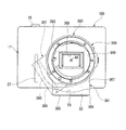
図5は、本実施形態の第2アダプター側マウント、可動部材310及び駆動装置320を示す平面図である。本実施形態の可動部材310及び駆動装置320は、光軸方向(Y軸方向)から見て第2アダプター側マウント362と重なる範囲に配置されている。可動部材310及び駆動装置320は、第2アダプター側マウント362に対して、交換レンズ200とは反対側(−Y方向)に配置されている。図5において、可動部材310及び駆動装置320は、第2アダプター側マウント362等を透かして模式的に図示されている。
FIG. 5 is a plan view showing the second adapter-side mount, the
本実施形態の可動部材310は、光軸AXを中心とする環のうち、光軸AXを中心とする周方向における所定の角度範囲α[°]を占める部分と概ね同じ形状(三日月形状、円弧形状)である。本実施形態において、角度範囲α[°]は、150°程度である。角度範囲α[°]は、例えば、180°以下でもよいし、120°以下でもよく、90°以下でもよい。可動部材310は、図5に記載の状態から、光軸AXを中心とする周方向に反時計回りに角度(θ1+θ2)[°]だけ回動可能に設けられている。
The
本実施形態の駆動装置320は、光軸方向(Y軸方向)から見て第2アダプター側マウント362の内周よりも内側の領域と第2アダプター側マウント362の外周よりも外側の領域とにまたがる範囲に設けられている。本実施形態の駆動装置320は、概ね−150°の角度位置に配置されている。駆動装置320は、光軸AXを中心とする周方向の所定の角度範囲で可動部材310を回動させる。可動部材310が反時計回りに最も移動できる位置まで回動している第1状態と、可動部材310が時計回りに最も移動できる位置まで回動している第2状態(後述する最大開口位置)とで、光軸AXを中心とする周方向における可動部材310の一端の回転位置が角度(θ1+θ2)[°]だけ変化する。すなわち、可動部材310が回動可能な第1範囲A1は、光軸AXを中心とする環のうち、光軸AXを中心とする周方向の角度範囲(α+θ1+θ2)[°]に相当する区間である。なお、図5に記載の可動部材310の状態は第2状態である。
The
本実施形態において、光軸AXを中心とする放射方向(第2アダプター側マウント362の径方向)に関して、可動部材310と光軸AXとの距離L1は、第2端子部330と光軸AXの距離L2とほぼ同じである。すなわち、光軸AXを中心とる放射方向に関して、可動部材310の一部と光軸AXとの距離は、第2端子部330の一部と光軸AXとの距離と同じである。第2端子部330は、可動部材310が最も第2端子部330に接近した状態(第2状態)において、光軸方向(Y軸方向)から見た可動部材310が第2端子部330の端子と重ならないように設定されている。すなわち、第2端子部330は、光軸AXを中心とする周方向において、可動部材310が回動可能な第1範囲A1を除く第2範囲A2に配置されている。
In the present embodiment, the distance L1 between the
本実施形態において、光軸AXを中心とする放射方向に関して、可動部材310と光軸AXとの距離L1は、ピン363と光軸AXの距離L3とほぼ同じである。すなわち、光軸AXを中心とする放射方向に関して、可動部材310の一部と光軸AXとの距離は、ピン363の一部と光軸AXとの距離と同じである。ピン363は、光軸AXを中心とする周方向において、可動部材310が回動可能な第1範囲A1を除く第2範囲A2に配置されている。
In the present embodiment, the distance L1 between the
図6は、本実施形態の可動部材310及び駆動装置320を示す斜視図である。図7は、本実施形態の駆動装置320を示す斜視図である。図8は、本実施形態の可動部材310及び駆動装置320を示す平面図である。図9は、本実施形態の支持ローラー387及び可動部材310を示す断面図である。図10は、本実施形態の可動部材310、駆動装置320、及び押え板393を示す平面図である。
図11は、本実施形態のアダプターの変形例を示す平面図である。
FIG. 6 is a perspective view showing the
FIG. 11 is a plan view showing a modification of the adapter of the present embodiment.
図6に示すように、本実施形態の可動部材310は、本体部371、第1接触部372、第1ギア部373、及びフランジ部374を含む。可動部材310は、第1ギア部373(入力部)が駆動装置320から受ける力(伝達されるトルク)によって回動する。本実施形態の可動部材310は、可動部材310の回動により第1接触部372(出力部)が交換レンズ200の絞り駆動部材203に対して力を作用させる(伝達する)ことによって、絞り駆動部材203を変位させる。
As shown in FIG. 6, the
本実施形態において、光軸方向(Y軸方向)から見た本体部371の外形は、光軸方向から見た可動部材310の外形と概ね同じである。本体部371は、光軸AXを中心とする環のうち、光軸AXを中心とする周方向における所定の角度範囲α[°]を占める部分と概ね同じ形状である。本実施形態の本体部371は、光軸方向において+Y方向を向く第1面375と、−Y方向を向く第2面376と、第1面375の外縁と第2面376の外縁とを結ぶ第3面377Aと第4面377Bとを有する。本実施形態の可動部材310は、第1面375を含む第1部材378と、第2面376を含む第2部材379とを含む。本実施形態において、第1部材378及び第2部材379は、それぞれ、樹脂材料を型成形すること等によって形成されている。なお、本体部371は、第1部材378及び第2部材379から形成されるのではなく、樹脂材料を一体形成してもよい。
In the present embodiment, the outer shape of the
本実施形態の第1接触部372は、本体部371に対して第2アダプター側マウント362と同じ側(+Y側)において、本体部371の第1部材375に取り付けられている。第1接触部372は、光軸方向において+Y方向から見て(−Y方向に見て)第2アダプター側マウント362の内周の内側へ張り出している。第1接触部372は、交換レンズ200の着状態において、交換レンズ200の絞り駆動部材203と接触する。交換レンズ200の絞り駆動部材203は、所定の方向(+Y側から見て反時計回り方向)に向って付勢されており、交換レンズ200の着状態において、この付勢力によって第1接触部372に押しつけられる。第1接触部372は、絞り駆動部材203と接触している状態で本体部371と一体的に回動することによって、絞り駆動部材203が付勢されている所定の方向に絞り駆動部材203を変位させる。
The
本実施形態の第1ギア部373は、駆動装置320の近傍に配置されている。本実施形態の第1ギア部373は、光軸AXを中心とする周方向の位置(角度位置)について、−180°以上−90°未満の角度範囲に配置されている。本実施形態の第1ギア部373は、本体部371のうち、光軸AXを中心とする放射方向において外側を向いた第4面377Bに取り付けられている。第1ギア部373は、光軸AXを中心とする放射方向において外側を向いた複数のギア歯を含む。第1ギア部373のピッチ円380の中心は、交換レンズ200の光軸AXとほぼ一致している。第1ギア部373の複数のギア歯は、ピッチ円380の周方向の一部に相当する範囲に配列されている。
The
本実施形態のフランジ部374は、光軸AXを中心とする周方向において、第1ギア部373とほぼ同じ角度範囲に設けられている。フランジ部374は、本体部371に対して第2アダプター側マウント362と同じ側(+Y方向)において、本体部371の第2部材376に取り付けられている。本実施形態のフランジ部374は、本体部371から光軸AXを中心とする放射方向の外側に向って、第1ギア部373の歯先よりも突出している。
The
図7に示すように、本実施形態の駆動装置320は、第2ギア部(動力伝達部)381、第2接触部382、アクチュエーター383、及びエンコーダー384を含む。
As shown in FIG. 7, the
本実施形態の第2ギア部381は、アクチュエーター383から入力された動力を第1ギア部373へ出力する。第2ギア部381は、複数のギアを含む。第2ギア部381は、複数のギアのうちの第1ギア385のギア歯が、第1ギア部373のギア歯と噛み合わされている。第1ギア385は、第1ギア部373に対して、光軸AXを中心とする放射方向に関する外側に配置されている。なお、動力伝達部は、アクチュエーター383から出力された動力を、摩擦等を利用して第1ギア部373へ伝達してもよい。
The
本実施形態の第2接触部382は環状である。第2接触部382の軸は、第2ギア部381の第1ギア385の回転軸と同軸となるように接続されている。第2接触部382は、第1ギア部373のフランジ部374と接触して、第1ギア部373と第2ギア部381の第1ギア385との間のギャップを形成している。すなわち、光軸AXを中心とする放射方向における第2接触部382とフランジ部374の寸法及び位置は、第1ギア部373の歯先が第1ギア385の歯元に到達しない状態において第1ギア部373と第2ギア部381の第1ギア385とが接触するように設定されている。
The
本実施形態のアクチュエーター383は、電動モータ−(ステッピングモーター)を含む。アクチュエーター383は、第2ギア部381と接続されている。アクチュエーター383は、第2ギア部381にトルクを供給し、第2ギア部381の第1ギア385を回転させる。第2ギア部381については後で詳述する。
The
本実施形態のエンコーダー384は、第2ギア部381の複数のギアのうち少なくとも1つのギアの回転状態を示す回転情報を検出する。ギアの回転状態は、ギアの回転速度と回転位置の少なくとも一方を含む。エンコーダー384は、検出した回転情報をアダプター制御部350へ出力する。
The
図8及び図9に示すように、本実施形態のアダプター300は、可動部材310の位置に関する位置情報を検出するセンサー386を含む。センサー386は、可動部材310の位置に関する情報を光学的に検出する。センサー386は、光軸AXを中心とする周方向において可動部材310が最も反時計回りに回動された状態であるか否かを、検出することができる。センサー386は、検出した位置情報をアダプター制御部350に出力する。
As shown in FIGS. 8 and 9, the
アダプター制御部350は、エンコーダー384から出力された回転情報とセンサー386から出力された位置情報の少なくとも一方に基づいて、アクチュエーター383を制御することによって、第2ギア部381の第1ギア385の回転状態を制御できる。アダプター制御部350は、第1ギア385の回転状態を制御することによって可動部材310の回転位置を制御し、結果として絞り駆動部材203の変位を制御できる。
The
図6及び図8に示すように、本実施形態のアダプター300は、可動部材310が光軸AXを中心とする周方向に円滑に回動可能なように、可動部材310を支持する支持ローラー387を有する。本実施形態において、支持ローラー387は、第1支持ローラー387A、第2支持ローラー387B、及び第3支持ローラー387Cを有する。
As shown in FIGS. 6 and 8, the
第1支持ローラー387Aは、可動部材310に対して、光軸AXを中心とする放射方向において内側に配置されている。第1支持ローラー387Aは、光軸AXを中心とする周方向における回転位置に関して、第2ギア部381よりも第1接触部372に近い位置に配置されている。第1支持ローラー387Aは、光軸方向(Y軸方向)から見て光軸AXと第1支持ローラー387Aの中心とを結ぶ仮想線が第1接触部372の可動範囲と交差するように、第1接触部372の近傍に配置されている。第3支持ローラー387Cは、可動部材310に対して、光軸AXを中心とする放射方向において外側に配置されている。第3支持ローラー387Cは、第1支持ローラー387Aとの間で可動部材310を挟むように配置されている。
The
第2支持ローラー387Bは、可動部材310に対して、光軸AXを中心とする放射方向において内側に配置されている。第2支持ローラー387Bは、第1支持ローラー387Aよりも第1ギア部373に近い位置に配置されている。第2支持ローラー387Bは、光軸方向(Y軸方向)から見て光軸AXと第2支持ローラー387Bの中心とを結ぶ仮想線が第1ギア部373と交差するように、第1ギア部373の近傍に配置されている。第2支持ローラー387Bは、第2ギア部381との間に可動部材310の第1ギア部373を挟むように配置されている。
The
本実施形態のアダプター300は、図8に示す保持部材392、及び図9に示す押え板393を含む。保持部材392は、第1収容部材360に固定されている。保持部材392は、押え板393と光軸方向(Y軸方向)において対向している。第1支持ローラー387A、第2支持ローラー387B、第3支持ローラー387C、及び可動部材310は、光軸方向の保持部材392と押え板393との間に配置されている。第1支持ローラー387A、第2支持ローラー387B、及び第3支持ローラー387Cは、それぞれの回転軸の一端が保持部材392に回転可能に支持されており、それぞれの回転軸の他端が押え板393に回転可能に支持されている。
The
可動部材310は、保持部材392と押え板393との間に、光軸AXを中心とする周方向における回動を妨げない程度のギャップを有して、保持部材392と押え板393とに挟まれている。可動部材310は、保持部材392と押え板393とに挟まれていることによって、光軸方向(Y軸方向)における移動が規制されている。
The
ところで、アダプター300は、可動部材が交換レンズ200の光軸を中心とする周方向の全周に設けられている場合に、可動部材を回動させる上で必要とされる駆動装置のパワーが増加し、大型になる可能性がある。また、アダプターは、可動部材が交換レンズ200の光軸を中心とする周方向の全周に設けられている場合に、可動部材を支持する機構が複雑になり、アダプターが大型になる可能性がある。
Incidentally, when the movable member is provided on the entire circumference in the circumferential direction centering on the optical axis of the
本実施形態のアダプター300は、可動部材310が交換レンズ200の光軸AXを中心とする周方向の一部に設けられているので、可動部材310を軽量にすることができる。したがって、アダプター300は、可動部材310を回動させる上で駆動装置320に必要とされるパワーを減らすことができ、装置サイズを小型にすることができる。また、アダプター300は、可動部材310が交換レンズ200の光軸AXの周方向の一部に設けられているので、可動部材310を支持する機構をシンプルにすることができ、装置サイズを小型にすることができる。
In the
本実施形態において、ピン363は、光軸AXの周方向に関して第1範囲A1の外側の第2範囲A2のうち、光軸AXに対する放射方向に関して光軸AXとの距離L3が光軸AXと可動部材310との距離L1とほぼ等しい位置に配置されている。したがって、アダプター300は、可動部材310がピン363と干渉(衝突)することを抑制しつつ、光軸AXに対する放射方向におけるアダプター300の寸法を小さくすることができ、装置サイズを小型にすることができる。
In the present embodiment, the
本実施形態において、第2端子部330は、光軸AXを中心とする周方向に関して第1範囲A1を除く第2範囲A2のうち、光軸AXを中心とする放射方向に関して光軸AXとの距離L2が光軸AXと可動部材310との距離L1とほぼ等しい位置に配置されている。したがって、アダプター300は、可動部材310が第2端子部330と干渉(衝突)することを抑制しつつ、光軸AXを中心する放射方向におけるアダプター300の寸法を小さくすることができ、装置サイズを小型にすることができる。
In the present embodiment, the second
ところで、可動部材は、回動に伴って保持部材又は押え板と干渉する程度に、光軸方向における寸法の誤差が生じることがありえる。また、アダプターは、可動部材が環状である場合に製造誤差等による可動部材の形状の歪みによって、可動部材の回動が妨げられるおそれがある。 By the way, the movable member may cause a dimensional error in the direction of the optical axis to the extent that the movable member interferes with the holding member or the pressing plate with the rotation. Further, when the movable member is annular, the adapter may be prevented from rotating by the distortion of the shape of the movable member due to manufacturing error or the like.
本実施形態のアダプター300は、可動部材310が交換レンズ200の光軸AXの周方向の一部に設けられているので、可動部材310の製造誤差等によって可動部材310の回動が妨げられることが防げる。
In the
ところで、本実施形態のアダプター300は、撮影時に三脚等の撮影用設置台に固定設置するための構造を含む。以下では、撮影用設置台の一例として三脚51(図10)を用いるものとして説明する。
図10は、アダプター300を一部中身を透過して示す側面図であり、図11は、アダプター300を光軸AXの方向から見た断面図である。図12は、装着状態にあるカメラボディ100とアダプター300と交換レンズ200Aを、一部中身を透過して示す側面図である。
これらの図に示すように、前述した第1収容部材360(第1筐体部)から下方に突出して一体的に形成されている第2収容部材361(第2筐体部)は、底部366の下面365の略中央に三脚固定用のねじ穴50aが設けられている。このねじ穴50aには、三脚51の座面51aから上方に突出する図示しない固定用のねじが締め込まれるようになっている。ねじ穴50aは、底部366の底壁に固定されたねじ受け部品50によって構成されている。なお、本実施形態のアダプター300においては、ねじ受け部品50が三脚51に対するアダプター300の取付座(アダプター側取付座)とされている。
By the way, the
10 is a side view showing the
As shown in these drawings, the second housing member 361 (second housing portion) integrally formed by projecting downward from the first housing member 360 (first housing portion) described above has a
図11に示すように、第1収容部材360から下方に突出する第2収容部材361は、その内部が中空状に形成されている。そしてその中空状の内部には、アクチュエーター383等の駆動装置320の少なくとも一部が配置されている。駆動装置320は、第2収容部材361の底部のほぼ中心(もしくは中央近傍)に配置されているねじ受け部品50の設置位置よりも外側に(ねじ穴50aを避けて、ねじ穴50aの設置位置の周囲位置に)配置されている。このように第2収容部材361内で部品配置をしたので、デッドスペースを生じることなく効率よく部品を配置でき、装置の小型化を図ることができる。なお、図11に示した符号52は、第1収容部材360内に設置された回路基板である。
As shown in FIG. 11, the
また、第2収容部材361の底部366は、図3,図4にも示すように、脚部367に対して光軸AX方向の交換レンズ200が脱着される側(以下、前方側と呼ぶものとする)に突出する厚肉の延長壁(突出部)53を備えている。延長壁53は、その先端側が第1収容部材360の前方側の端面よりさらに前方側に突出している。延長壁53の上面の一部は、切り欠いた形状になっている。本実施形態ではこの切り欠き部分を、光軸AXを中心とする一定円弧形状を切り欠く円弧溝(凹部)54として形成している。
Further, as shown in FIGS. 3 and 4, the
一方、カメラボディ100の下面55の中央部には、図12に示すように三脚51の座面51a(図10参照)から突出するねじ(図示せず)が締め込まれるねじ穴56aが設けられている。このねじ穴56aもアダプター300のねじ穴50aと同様にカメラボディ100の底壁に固定されたねじ受け部品56によって構成されている。この実施形態においては、カメラボディ100の下面55が三脚51に対するカメラボディ100の取付座(カメラボディ側取付座)とされている。
On the other hand, a
アダプター300をカメラボディ100に接続した状態において、アダプター300の下面365とねじ受け部品50(アダプター側取付座)の下面の高さは、カメラボディ100を正位置撮影状態(横位置撮影状態)に構えたときに、図12に示すように、カメラボディ100の下面55の高さよりも所定寸法H1だけ低くなるように設定されている。この寸法H1は、アダプター300をカメラボディ100に接続した状態において、アダプター300の下面365を三脚51の座面51a上に固定するときに、三脚51の座面51aがカメラボディ100の下面55と干渉することのない寸法に設定されている。
When the
また、アダプター300の第2収容部材361(第2筐体部)は、第1収容部材(第1筐体部)360のカメラボディ100側の端面に対して前方側(図12中の左側/交換レンズの装着部分寄り)にずらして形成されている(換言すれば、両筐体部の持つ、カメラボディ100に対向する各対向面について、第2筐体部の対向面は、第1筐体部の対向面(第1面)よりもカメラボディ100側から大きく離間する配置となるように形成されている)。具体的には、アダプター300をカメラボディ100に接続したときに、カメラボディ100との間に光軸AX方向に所定の隙間D1ができる程度に、第2収容部材361は、第1収容部材360のカメラボディ100側の端面に対して前方側にずらして形成されている。このように第2収容部材361を僅か(隙間D1が出来る程度)に前方側にずらしている構造によって、アダプター300をカメラボディ100に着脱する際に、アダプター300がカメラボディ100と干渉しないようにすることができる。これについて図13を用いて説明する。
In addition, the second housing member 361 (second housing portion) of the
図13は、アダプター300をカメラボディ100に対して光軸AX回りに回動して脱着操作するときの様子を仮想線で示した正面図である。
カメラボディ100の前面(マウントが設けられている面)上には、その前面から突出して設けられている部品(例えば把持用の(指掛け用の)凸部57や不図示の操作ボタン等)を備える場合がある。アダプター300の裏面(アダプター300とカメラボディ100との着脱時にアダプター300の第2収容部材361がカメラボディ100の前面と対向する面)は、カメラボディ100側のマウント部に対してアダプター300を装着/取外しする際には、図13に点線で示すように、アダプター300がカメラボディ100に対して回動する。上述のように第2収容部材361が第1収容部材360よりも前面側(交換レンズの装着面側)に、上述の隙間D1が出来る程度に突出して形成されていることによって、この着脱時の回動の際に、第2収容部材361の裏面がカメラボディ100の前面上の突出部品(例えば把持用の凸部57)と干渉せずに着脱することが出来る。
FIG. 13 is a front view showing, in phantom lines, a state when the
On the front surface (surface on which the mount is provided) of the
ここで、アダプター300の第2アダプター側マウント362には、図1に示すような三脚取付用の座面を備えていない交換レンズ200以外にも、図12に示すような三脚取付用の座面を備えた交換レンズ200Aを取り付けることができる。図12に示す交換レンズ200Aは、鏡筒206の外周面に鉛直下方に突出する断面略L字状のブラケット58が取り付けられ、ブラケット58の延出部の下面59が三脚取付用の座面とされている。
ブラケット58の下面59の中央部には、三脚51の座面51aから突出するねじ(図示せず)が締め込まれるねじ穴60aが設けられている。このねじ穴60aもアダプター300のねじ穴50aと同様にブラケット58の底壁に固定されたねじ受け部品60によって構成されている。この実施形態においては、ブラケット58の下面59が三脚51に対する交換レンズ200Aの取付座(交換レンズ側取付座)とされている。
Here, the second adapter-
A
アダプター300の下面365の高さは、図12に示すように、アダプター300に交換レンズ200Aを接続した状態において、交換レンズ200Aのブラケット58の下面59の高さよりも所定寸法H2だけ高くなるように設定されている。この寸法H2は、アタプター300の第1収容部材360の一端に交換レンズ200Aを接続し、第2収容部材361の他端をカメラボディ100に接続した状態において、ブラケット58の下面59を三脚51の座面51a上に固定したときに、三脚51の座面51aがアダプター300の第2収容部材361の下面365と干渉することのない寸法に設定されている。
As shown in FIG. 12, the height of the
図14,図15は、シフト・アオリ撮影用の交換レンズ200Bをアダプター300に接続したときの、本実施形態のカメラシステム1の側面図と正面図である。
交換レンズ200Bは、アダプター接続側の光軸AX方向の端部に、アダプター300に対して脱着可能なマウント部61を備えている。マウント部61よりも前方側(図14の左側/被写体側)には、アオリ撮影用の回動機構62が設けられている。マウント部61の外周部(外周部の下方)には、回動機構62のロックとロック解除を操作するための操作レバー63が突出して設けられている。操作レバー63は、交換レンズ200Bをアダプター300に装着したときに、側面視でアダプター300の第2収容部材361の延長壁(突出部)53と一部重なる位置に突出している。しかし、延長壁53の上面には、既述(図3,4参照)したように第2アダプター側マウント362に面する側に円弧溝(凹部)54が設けられているため、操作レバー63は延長壁53と干渉することはない。つまり、円弧溝54の内面の成す円弧は、操作レバー63の先端部の光軸AX回りの回動軌道よりも径方向外側となるように設定されている(図15参照)。
なお、アダプター300の第1収容部材360の前方側の端面には、交換レンズ200(200A,200B)を装着しないときに、図示しないカバーキャップを取り付けることがあるが、延長壁53上の円弧溝54は、このカバーキャップの脱着の際に、使用者の指先が延長壁53の上面と干渉して操作を阻害されるのを防ぐようにも機能する。
14 and 15 are a side view and a front view of the
The
Note that a cover cap (not shown) may be attached to the front end surface of the
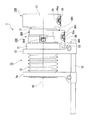
図16は、接写用のベローズアタッチメント70をアダプター300に接続したときの本実施形態のカメラシステム1の側面図である。なお、ベローズアタッチメント70に取り付けられる接写用のレンズは、図16において図示が省略されている。
ベローズアタッチメント70は、アダプター300に対して脱着可能なマウント部71と、マウント部71に結合される後部支持枠72と、ベローズ73を挟んで後部支持枠72の前方側に配置される前部支持枠74と、後部支持枠72に結合されるとともに前部支持枠74をスライド可能に支持するガイドフレーム75とを備えている。図示しない接写用の交換レンズは前部支持枠74側に取り付けられる。
FIG. 16 is a side view of the
The
アダプター300の第2収容部材361の底部366には前述のように延長壁53が設けられ、その延長壁53の端部は第1収容部材360の端面よりも前方側に突出しているが、延長壁53の第1収容部材360からの突出量は、アタプター300にベローズアタッチメント70を接続したときに、ベローズアタッチメント70の後部支持枠72と干渉しない寸法に設定されている。またアダプター300の下面365の高さについても、図16に示すように、ベローズアタッチメント70の後部支持枠72やガイドフレーム75と干渉しない寸法に設定されている。
The
以上のように本実施形態のアダプター300は、第1収容部材(第1筐体部)360から下方に突出する第2収容部材(第2筐体部)361側に、電気部品であるアクチュエーター383等の駆動装置320の少なくとも一部が配置されている。そしてその駆動装置320の一部(アクチュエータ383等)は、第2収容部材361底部の中央近傍に配置されているねじ受け部品50よりも外側に(周囲に)配置しているので、第2収容部材361内で部品配置を効率的にでき、装置を小型化できる。
As described above, the
また、本実施形態のアダプター300は、三脚51に取り付けられる下面365が、カメラボディ100の下面55(カメラボディ側取付座)よりも所定寸法H1だけ低くなるように(光軸AXを中心として放射方向に関して外側になるように)設定されているため、図1に示すように三脚取付用の取付座を備えていない交換レンズ200を接続して用いる場合に、カメラボディ100と三脚51の干渉を招くことなく、アダプター300の下面365を三脚51の座面51aに確実に固定することができる。したがって、このアダプター300を用いるカメラシステム1においては、カメラボディ100から交換レンズ200の重心位置までの距離がアダプター300の軸長分だけ長くなっても、三脚51の座面51aをアダプター300に固定することにより、三脚51のバランスを良好に保つことができる。
In addition, the
また、本実施形態のアダプター300(アダプター本体)は、カメラボディ100と交換レンズ200(200A,200B)に対して脱着可能な筒状の第1収容部材360と、第1収容部材360から径方向外側に突出する第2収容部材361とを備え、三脚取付用のアダプター側取付座が第2収容部材361の下面365(端部)に設定されているため、第1収容部材360の周域全体を拡大することなく、三脚取付用のアダプター側取付座を適正高さに設定することができる。したがって、アダプター300のコンパクト化を図ることができる。
The adapter 300 (adapter body) of the present embodiment includes a cylindrical
さらに、本実施形態のアダプター300は、第1収容部材360から鉛直下方に向かって突出する第2収容部材361の内部に、重量物であるアクチュエーター383等の駆動装置320の一部が配置されているため、カメラシステム1のバランス、特に、アダプター300を三脚51に固定設置したときのカメラシステム1のバランスを良好に維持することができる。
Furthermore, in the
また、本実施形態のアダプター300においては、三脚51に取り付けられる下面365が、交換レンズ200Aのブラケット58の下面59(レンズ側取付座)よりも所定寸法H2だけ高くなるように(光軸AXを中心として放射方向に関して内側になるように)設定されているため、図12に示すような三脚取付用の取付座を有する交換レンズ200Aを接続して用いる場合に、三脚51とアダプター300やカメラボディ100との干渉を招くことなく、交換レンズ200Aのブラケット58を三脚51の座面51aに確実に固定することができる。
Further, in the
なお、本発明の技術範囲は上記の実施形態に限定されるものではない。例えば、上記の実施形態のアダプター300は、円筒状の第1収容部材360の外周に径方向外側の一方に膨出するように箱状の第2収容部361が設けられているが、図17に示すアダプター300Aのように、円筒状の第1収容部材360の外周に三方に膨出するように箱状の第2収容部材361Aを設けるようにしても良い。また、図18に示すアダプター300Bのように、円筒状の第1収容部材360の外周に四方に膨出するように箱状の第2収容部材361Bを設けるようにしても良い。これらの例の場合、第2収容部材361A,361Bの各突出端は平坦に形成され、これらの各端面には三脚取付用のねじ穴50aを有するねじ受け部品50が取り付けられている。
上記の実施形態で説明した要件のうち少なくとも1つの要件は、省略される場合がある。上記の実施形態で説明した各要件は、適宜、組み合わせることができる。
The technical scope of the present invention is not limited to the above embodiment. For example, the
At least one of the requirements described in the above embodiments may be omitted. The requirements described in the above embodiments can be combined as appropriate.
1・・・カメラシステム、31・・・第1アダプター側マウント(第1マウント部)、50・・・ねじ受け部品(アダプター側取付座)、51・・三脚(撮影用設置台)、53・・・延長壁(突出部)、54・・・円弧溝、55・・・下面(カメラボディ側取付座)、59・・・下面(レンズ側取付座)、100・・・カメラボディ、200,200A,200B・・・交換レンズ、300・・・アダプター(アダプター本体)、310・・・可動部材(被駆動部材)、320・・・駆動装置(駆動系)、360・・第1収容部材(第1筐体部)、361・・・第2収容部材(第2筐体部)、362・・・第2アダプター側マウント(第2マウント部)、365・・下面(アダプター側取付座)。
DESCRIPTION OF
Claims (7)
前記第1筐体部と一体的に構成されている第2筐体部と、
前記第2筐体部に設けられており、撮影用設置台に対して着脱可能なアダプター側取付座と、を有し、
前記第1マウント部は、前記第1筐体部の第1面側に設けられており、
前記第2筐体部は、前記第1面側の面とは反対側において、前記第1筐体部の前記反対側の端面よりも更に前記反対側に突出した突出部を備えており、
前記アダプター側取付座は、前記撮影用設置台に着脱可能なレンズ側取付座を備える前記交換レンズを前記第2マウント部に装着している場合には、前記レンズ側取付座よりも、前記交換レンズの光軸を中心とした放射方向に関して内側になるように配置されている、ことを特徴とするアダプター。 The first mount part to which the camera body can be attached and detached via the camera body side mount and the first mount part are provided separately and exchanged via an interchangeable lens side mount that is different in size from the camera body side mount. A first housing part comprising a second mount part to which the lens can be attached and detached;
A second housing part configured integrally with the first housing part;
An adapter-side mounting seat that is provided in the second housing portion and is detachable from the photographing installation base;
The first mount part is provided on the first surface side of the first housing part,
The second housing portion includes a protruding portion that protrudes further to the opposite side than the opposite end surface of the first housing portion on the side opposite to the surface on the first surface side,
When the interchangeable lens is mounted on the second mount portion, the adapter-side mounting seat has the lens-side mounting seat that can be attached to and detached from the photographing installation base. An adapter, which is arranged so as to be inward with respect to a radial direction centered on the optical axis of the lens.
前記第2筐体部は、前記アダプター側取付座を前記第1筐体部とは反対側に備え、
前記アダプター側取付座は、前記反対側において前記第2筐体部の中央近傍に配置されており、
前記駆動系の少なくとも一部は、前記第2筐体部内において、前記アダプター側取付座の周囲に配置されていることを特徴とする請求項1または請求項2に記載のアダプター。 The adapter further includes a driven member and a drive system that drives the driven member,
The second housing portion includes the adapter side mounting seat on the side opposite to the first housing portion,
The adapter side mounting seat is disposed in the vicinity of the center of the second housing part on the opposite side,
The adapter according to claim 1, wherein at least a part of the drive system is disposed around the adapter side mounting seat in the second housing part.
前記第1マウント部に装着されたカメラボディと、
前記第2マウント部に装着された交換レンズと、を備えるカメラシステム。 The adapter according to any one of claims 1 to 6,
A camera body attached to the first mount;
An interchangeable lens mounted on the second mount unit.
Priority Applications (5)
| Application Number | Priority Date | Filing Date | Title |
|---|---|---|---|
| JP2011160813A JP5418551B2 (en) | 2011-07-22 | 2011-07-22 | Adapter and camera system |
| US13/548,952 US8678678B2 (en) | 2011-07-22 | 2012-07-13 | Adapter and camera system |
| CN2012203468005U CN202815394U (en) | 2011-07-22 | 2012-07-17 | Adapter and camera system |
| CN201210247707.3A CN102890390B (en) | 2011-07-22 | 2012-07-17 | Adapter |
| CN201710444186.3A CN107357117A (en) | 2011-07-22 | 2012-07-17 | Adapter and camera system |
Applications Claiming Priority (1)
| Application Number | Priority Date | Filing Date | Title |
|---|---|---|---|
| JP2011160813A JP5418551B2 (en) | 2011-07-22 | 2011-07-22 | Adapter and camera system |
Publications (3)
| Publication Number | Publication Date |
|---|---|
| JP2013025156A JP2013025156A (en) | 2013-02-04 |
| JP2013025156A5 JP2013025156A5 (en) | 2013-04-18 |
| JP5418551B2 true JP5418551B2 (en) | 2014-02-19 |
Family
ID=47533934
Family Applications (1)
| Application Number | Title | Priority Date | Filing Date |
|---|---|---|---|
| JP2011160813A Active JP5418551B2 (en) | 2011-07-22 | 2011-07-22 | Adapter and camera system |
Country Status (3)
| Country | Link |
|---|---|
| US (1) | US8678678B2 (en) |
| JP (1) | JP5418551B2 (en) |
| CN (3) | CN107357117A (en) |
Families Citing this family (19)
| Publication number | Priority date | Publication date | Assignee | Title |
|---|---|---|---|---|
| JP5418551B2 (en) * | 2011-07-22 | 2014-02-19 | 株式会社ニコン | Adapter and camera system |
| GB2515807B (en) * | 2013-07-05 | 2017-09-13 | Global Boom Int Ltd | A lens adapter |
| USD722100S1 (en) * | 2013-07-24 | 2015-02-03 | Sony Corporation | Adapter |
| JP1524805S (en) * | 2013-12-31 | 2015-06-01 | ||
| USD745590S1 (en) * | 2013-12-31 | 2015-12-15 | Samsung Electronics Co., Ltd. | Lens for camera |
| US9535260B2 (en) * | 2014-02-20 | 2017-01-03 | Canon Kabushiki Kaisha | Adapter having tilt-shift unit, and camera system |
| JP2015215422A (en) * | 2014-05-08 | 2015-12-03 | ソニー株式会社 | Imaging apparatus |
| US9383631B2 (en) * | 2014-06-18 | 2016-07-05 | Asferik, Llc | Camera carrying and mounting system |
| JP6268658B2 (en) * | 2014-06-27 | 2018-01-31 | エスゼット ディージェイアイ オスモ テクノロジー カンパニー リミテッドSZ DJI Osmo Technology Co., Ltd. | Lens holder assembly and pan head using the same |
| US9885940B2 (en) | 2015-01-21 | 2018-02-06 | Asferik, Llc | Camera carrying and mounting system |
| USD768224S1 (en) * | 2015-03-20 | 2016-10-04 | Samyang Optics Co., Ltd | Camera lens |
| USD763942S1 (en) * | 2015-03-20 | 2016-08-16 | Samyang Optics Co., Ltd | Camera lens |
| JP6672696B2 (en) * | 2015-10-22 | 2020-03-25 | 株式会社ニコン | Lens barrel and camera body |
| WO2017115465A1 (en) * | 2015-12-28 | 2017-07-06 | パナソニックIpマネジメント株式会社 | Lens barrel and camera provided with same |
| DE102016220370A1 (en) * | 2016-10-18 | 2018-04-19 | Carl Zeiss Ag | Adapter device and camera lens |
| CN108072954B (en) * | 2016-11-15 | 2023-11-24 | 深圳光峰科技股份有限公司 | Lens sealing sleeve, lens module, lens adjusting module and projection equipment |
| JP7171340B2 (en) | 2018-09-26 | 2022-11-15 | キヤノン株式会社 | Adapter device, camera system, control method, program |
| US10775683B1 (en) | 2019-07-19 | 2020-09-15 | Richard C. Hallett | Multi-camera multi-position adapter |
| US10578953B1 (en) | 2019-07-19 | 2020-03-03 | Richard Hallett | View camera adapter |
Family Cites Families (30)
| Publication number | Priority date | Publication date | Assignee | Title |
|---|---|---|---|---|
| JPS63191136A (en) | 1987-02-03 | 1988-08-08 | Olympus Optical Co Ltd | Replacing lens adaptor for electronic camera |
| JPH0234824A (en) | 1988-07-25 | 1990-02-05 | Canon Inc | Mount adaptor |
| JP2720520B2 (en) * | 1989-06-06 | 1998-03-04 | 株式会社ニコン | Remotely controllable camera system and zoom ring drive |
| US5467158A (en) | 1990-09-07 | 1995-11-14 | Minolta Camera Kabushiki Kaisha | Film winding/rewinding mechanism of camera |
| JP2910198B2 (en) | 1990-09-12 | 1999-06-23 | ミノルタ株式会社 | Camera shutter mechanism |
| JPH04116631A (en) | 1990-09-07 | 1992-04-17 | Minolta Camera Co Ltd | Diaphragm driving mechanism of camera |
| JPH05249356A (en) | 1991-10-14 | 1993-09-28 | Canon Inc | Lens barrel holder |
| JPH05181188A (en) | 1992-01-06 | 1993-07-23 | Canon Inc | Intermediate accessary for camera |
| JPH06317737A (en) | 1993-05-07 | 1994-11-15 | Olympus Optical Co Ltd | Enlarging and photographing device |
| US5594517A (en) | 1993-05-07 | 1997-01-14 | Olympus Optical Co., Ltd. | Enlargement photographing apparatus |
| JP3544563B2 (en) * | 1994-06-14 | 2004-07-21 | オリンパス株式会社 | Camera system and intermediate adapter |
| JPH08122605A (en) * | 1994-10-24 | 1996-05-17 | Nikon Corp | Lens barrel supporting unit |
| JPH08194249A (en) * | 1995-01-19 | 1996-07-30 | Nikon Corp | Lens mount converter |
| JPH08286109A (en) * | 1995-04-18 | 1996-11-01 | Sony Corp | Lens adapter for video camera |
| JPH0915722A (en) * | 1995-06-27 | 1997-01-17 | Canon Inc | Lens barrel |
| JP2002014405A (en) | 2000-06-30 | 2002-01-18 | Nikon Corp | Lens adapter for electronic camera and electronic camera |
| FR2821172B1 (en) * | 2001-02-16 | 2003-05-23 | Immervision Internat Pte Ltd | METHOD AND DEVICE FOR ORIENTATION OF A DIGITAL PANORAMIC IMAGE |
| JP2003255426A (en) | 2002-03-06 | 2003-09-10 | Fuji Photo Optical Co Ltd | Vibrationproof adapter |
| JP3885661B2 (en) * | 2002-05-21 | 2007-02-21 | 株式会社ニコン | Lens barrel |
| JP3951299B2 (en) | 2003-02-20 | 2007-08-01 | ソニー株式会社 | Lens adapter |
| JP2005017375A (en) | 2003-06-23 | 2005-01-20 | Olympus Corp | Lens barrel holder and lens barrel holder-attachable/detachable lens barrel |
| TWI234684B (en) * | 2004-03-29 | 2005-06-21 | Long Perng Co Ltd | Optical equipment converter |
| JP4299208B2 (en) | 2004-08-20 | 2009-07-22 | 日本電子株式会社 | 3D image construction method |
| JP2006301291A (en) * | 2005-04-20 | 2006-11-02 | Fujinon Corp | Lens barrel |
| US7636203B2 (en) | 2005-04-20 | 2009-12-22 | Fujinon Corporation | Lens barrel |
| US7813632B2 (en) * | 2005-12-07 | 2010-10-12 | Nocturnal Devices, Llc | Optical adapter system and method |
| JP5036023B2 (en) | 2006-01-19 | 2012-09-26 | 株式会社 ニコンビジョン | Imaging device and eyepiece |
| JP2007243928A (en) | 2006-02-09 | 2007-09-20 | Nippon Hoso Kyokai <Nhk> | Gradation nd filter unit for television camera, nd adapter, and television camera |
| JP5532829B2 (en) | 2009-11-06 | 2014-06-25 | 株式会社ニコン | Support device and camera system |
| JP5418551B2 (en) * | 2011-07-22 | 2014-02-19 | 株式会社ニコン | Adapter and camera system |
-
2011
- 2011-07-22 JP JP2011160813A patent/JP5418551B2/en active Active
-
2012
- 2012-07-13 US US13/548,952 patent/US8678678B2/en active Active
- 2012-07-17 CN CN201710444186.3A patent/CN107357117A/en active Pending
- 2012-07-17 CN CN201210247707.3A patent/CN102890390B/en active Active
- 2012-07-17 CN CN2012203468005U patent/CN202815394U/en not_active Expired - Fee Related
Also Published As
| Publication number | Publication date |
|---|---|
| CN202815394U (en) | 2013-03-20 |
| US8678678B2 (en) | 2014-03-25 |
| US20130022347A1 (en) | 2013-01-24 |
| CN102890390A (en) | 2013-01-23 |
| CN102890390B (en) | 2017-07-11 |
| CN107357117A (en) | 2017-11-17 |
| JP2013025156A (en) | 2013-02-04 |
Similar Documents
| Publication | Publication Date | Title |
|---|---|---|
| JP5418551B2 (en) | Adapter and camera system | |
| CN108989620B (en) | Accessory, image pickup apparatus capable of mounting accessory, and camera system | |
| CN108989624B (en) | Accessory, image pickup apparatus capable of mounting accessory, and camera system | |
| JP2007025378A (en) | Universal head system | |
| US8405922B2 (en) | Lens barrel and imaging device and hand-held data terminal device including the same | |
| US20150212395A1 (en) | Imaging apparatus and imaging system | |
| US20130308211A1 (en) | Optical apparatus including decentering/tilting adjustment mechanism | |
| JP6459984B2 (en) | Camera and adapter | |
| JP2013061513A (en) | Lens barrel | |
| JP5884057B2 (en) | Lens barrel | |
| JP5849561B2 (en) | Adapter and camera system | |
| US7116901B2 (en) | Zoom finder drive mechanisms | |
| JP6332249B2 (en) | adapter | |
| JP2013025153A (en) | Adaptor and camera system | |
| JP6566080B2 (en) | adapter | |
| JP2013009107A (en) | Imaging apparatus | |
| JP2010060976A (en) | Camera and guide member | |
| JP2013025154A (en) | Adaptor and camera system | |
| JP5825901B2 (en) | Adapter and camera system | |
| WO2020217869A1 (en) | Lens barrel and image capture device | |
| JP4891610B2 (en) | Lens driving device and portable information terminal device | |
| CN114137684A (en) | Camera follow focus device and camera bearing device | |
| JP2015031727A (en) | Lens interchangeable-type camera | |
| JP4891609B2 (en) | Lens driving device and portable information terminal device | |
| JP2011221299A (en) | Attaching/detaching mechanism of front accessory of photographic lens |
Legal Events
| Date | Code | Title | Description |
|---|---|---|---|
| A621 | Written request for application examination |
Free format text: JAPANESE INTERMEDIATE CODE: A621 Effective date: 20130208 |
|
| A521 | Request for written amendment filed |
Free format text: JAPANESE INTERMEDIATE CODE: A523 Effective date: 20130304 |
|
| A977 | Report on retrieval |
Free format text: JAPANESE INTERMEDIATE CODE: A971007 Effective date: 20130528 |
|
| A131 | Notification of reasons for refusal |
Free format text: JAPANESE INTERMEDIATE CODE: A131 Effective date: 20130604 |
|
| A521 | Request for written amendment filed |
Free format text: JAPANESE INTERMEDIATE CODE: A523 Effective date: 20130802 |
|
| TRDD | Decision of grant or rejection written | ||
| A01 | Written decision to grant a patent or to grant a registration (utility model) |
Free format text: JAPANESE INTERMEDIATE CODE: A01 Effective date: 20131022 |
|
| A61 | First payment of annual fees (during grant procedure) |
Free format text: JAPANESE INTERMEDIATE CODE: A61 Effective date: 20131104 |
|
| R150 | Certificate of patent or registration of utility model |
Ref document number: 5418551 Country of ref document: JP Free format text: JAPANESE INTERMEDIATE CODE: R150 |
|
| R250 | Receipt of annual fees |
Free format text: JAPANESE INTERMEDIATE CODE: R250 |
|
| R250 | Receipt of annual fees |
Free format text: JAPANESE INTERMEDIATE CODE: R250 |
|
| R250 | Receipt of annual fees |
Free format text: JAPANESE INTERMEDIATE CODE: R250 |
|
| R250 | Receipt of annual fees |
Free format text: JAPANESE INTERMEDIATE CODE: R250 |
|
| R250 | Receipt of annual fees |
Free format text: JAPANESE INTERMEDIATE CODE: R250 |
|
| R250 | Receipt of annual fees |
Free format text: JAPANESE INTERMEDIATE CODE: R250 |
|
| R250 | Receipt of annual fees |
Free format text: JAPANESE INTERMEDIATE CODE: R250 |
|
| R250 | Receipt of annual fees |
Free format text: JAPANESE INTERMEDIATE CODE: R250 |