WO2017115465A1 - Lens barrel and camera provided with same - Google Patents
Lens barrel and camera provided with same Download PDFInfo
- Publication number
- WO2017115465A1 WO2017115465A1 PCT/JP2016/005233 JP2016005233W WO2017115465A1 WO 2017115465 A1 WO2017115465 A1 WO 2017115465A1 JP 2016005233 W JP2016005233 W JP 2016005233W WO 2017115465 A1 WO2017115465 A1 WO 2017115465A1
- Authority
- WO
- WIPO (PCT)
- Prior art keywords
- tripod
- lens barrel
- rear frame
- frame
- camera body
- Prior art date
Links
Images


Classifications
-
- G—PHYSICS
- G03—PHOTOGRAPHY; CINEMATOGRAPHY; ANALOGOUS TECHNIQUES USING WAVES OTHER THAN OPTICAL WAVES; ELECTROGRAPHY; HOLOGRAPHY
- G03B—APPARATUS OR ARRANGEMENTS FOR TAKING PHOTOGRAPHS OR FOR PROJECTING OR VIEWING THEM; APPARATUS OR ARRANGEMENTS EMPLOYING ANALOGOUS TECHNIQUES USING WAVES OTHER THAN OPTICAL WAVES; ACCESSORIES THEREFOR
- G03B17/00—Details of cameras or camera bodies; Accessories therefor
- G03B17/02—Bodies
- G03B17/12—Bodies with means for supporting objectives, supplementary lenses, filters, masks, or turrets
- G03B17/14—Bodies with means for supporting objectives, supplementary lenses, filters, masks, or turrets interchangeably
-
- G—PHYSICS
- G02—OPTICS
- G02B—OPTICAL ELEMENTS, SYSTEMS OR APPARATUS
- G02B7/00—Mountings, adjusting means, or light-tight connections, for optical elements
- G02B7/02—Mountings, adjusting means, or light-tight connections, for optical elements for lenses
- G02B7/021—Mountings, adjusting means, or light-tight connections, for optical elements for lenses for more than one lens
-
- G—PHYSICS
- G02—OPTICS
- G02B—OPTICAL ELEMENTS, SYSTEMS OR APPARATUS
- G02B7/00—Mountings, adjusting means, or light-tight connections, for optical elements
- G02B7/02—Mountings, adjusting means, or light-tight connections, for optical elements for lenses
- G02B7/14—Mountings, adjusting means, or light-tight connections, for optical elements for lenses adapted to interchange lenses
-
- G—PHYSICS
- G03—PHOTOGRAPHY; CINEMATOGRAPHY; ANALOGOUS TECHNIQUES USING WAVES OTHER THAN OPTICAL WAVES; ELECTROGRAPHY; HOLOGRAPHY
- G03B—APPARATUS OR ARRANGEMENTS FOR TAKING PHOTOGRAPHS OR FOR PROJECTING OR VIEWING THEM; APPARATUS OR ARRANGEMENTS EMPLOYING ANALOGOUS TECHNIQUES USING WAVES OTHER THAN OPTICAL WAVES; ACCESSORIES THEREFOR
- G03B17/00—Details of cameras or camera bodies; Accessories therefor
- G03B17/56—Accessories
- G03B17/561—Support related camera accessories
-
- G—PHYSICS
- G03—PHOTOGRAPHY; CINEMATOGRAPHY; ANALOGOUS TECHNIQUES USING WAVES OTHER THAN OPTICAL WAVES; ELECTROGRAPHY; HOLOGRAPHY
- G03B—APPARATUS OR ARRANGEMENTS FOR TAKING PHOTOGRAPHS OR FOR PROJECTING OR VIEWING THEM; APPARATUS OR ARRANGEMENTS EMPLOYING ANALOGOUS TECHNIQUES USING WAVES OTHER THAN OPTICAL WAVES; ACCESSORIES THEREFOR
- G03B17/00—Details of cameras or camera bodies; Accessories therefor
- G03B17/56—Accessories
- G03B17/565—Optical accessories, e.g. converters for close-up photography, tele-convertors, wide-angle convertors
Definitions
- the exterior unit (front frame) 19 is a cylindrical member constituting the exterior part (outer peripheral surface) of the lens barrel 10 as shown in FIGS. 1A and 4.
- An annular focus ring, zoom ring or the like is attached to the outer peripheral surface of the exterior unit 19 in a rotatable state.
- the rear frame 20 is attached to the end of the exterior unit 19 opposite to the subject.
- the rear frame 20 and the exterior unit 19 together constitute an exterior portion of the lens barrel 10.
- the rear frame 20 is attached so as to be rotatable relative to the mount base 18 and the exterior unit 19.
- the tripod base 21 is a pedestal to which a tripod (not shown) is connected.
- the tripod seat 21 is attached to the outer peripheral surface of the tripod base ring 20 a that constitutes the exterior portion of the lens barrel 10.
- the tripod seat 21 has a tripod screw 21a, a screw 21b, a tripod base 21c, a screw 21d, a screw 21e, and a cover 21f.
- the cylindrical part 21aa is attached in a state of being inserted into the opening part (attachment part 20aa) formed in the tripod base ring 20a.
- the lock screw 22b has a male screw portion 22ba to be attached to the tripod base ring 20a. Then, as shown in FIGS. 7 and 8, the lock screw 22b is fixed to the back surface side of the rotary knob 22a using two screws 22c.
- a tripod seat may be provided on the rear frame in which the tripod base ring 20a portion and the switch unit frame 20b portion cannot be divided and are integrated.
- a lens barrel having a tripod seat attached to another exterior part may be used.
Abstract
Provided is a lens barrel (10) that can be detachably attached to a camera body and that is provided with an exterior unit (19), a rear frame (20), a tripod mount (21), and a tripod lock screw (22). The exterior unit (19) includes an optical system. The rear frame (20) is attached to the exterior unit (19) so as to be capable of rotating about an optical axis. The outer peripheral surface of the lens barrel (10) is configured from the exterior unit (19) and the rear frame (20). The tripod mount (21) is provided to the rear frame (20) in order to be fixed to a tripod. The tripod lock screw (22) fixes the rotation position, about the optical axis, of the rear frame (20) in relation to the camera body at a prescribed rotation position while the lens barrel (10) is attached to the camera body.
Description
本開示は、レンズ鏡筒およびこれを備えたカメラに関する。
The present disclosure relates to a lens barrel and a camera including the lens barrel.
焦点距離が長いレンズ鏡筒は、一般的なレンズ鏡筒よりも大型化し重量が大きくなる。このため、焦点距離が長いレンズ鏡筒がカメラ本体へ装着されると、カメラの重心位置が被写体側へ移動する。この結果、カメラ本体側に三脚を接続した場合には、カメラの重心位置が被写体側に移動するため、被写体側へ倒れてしまうおそれがある。
The lens barrel with a long focal length is larger and heavier than a general lens barrel. For this reason, when a lens barrel having a long focal length is attached to the camera body, the position of the center of gravity of the camera moves to the subject side. As a result, when a tripod is connected to the camera body side, the center of gravity of the camera moves to the subject side, which may cause the camera to fall to the subject side.
そこで、焦点距離が長いレンズ鏡筒を装着したカメラをバランスよく三脚で支持するために、三脚座を備えたレンズ鏡筒が用いられている。
Therefore, in order to support a camera equipped with a lens barrel having a long focal length with a tripod in a balanced manner, a lens barrel having a tripod seat is used.
特許文献1には、三脚座が三脚リングを介して外装環に取り付けられたレンズ鏡筒について開示されている。
Patent Document 1 discloses a lens barrel in which a tripod mount is attached to an exterior ring via a tripod ring.
リング式の回転三脚座を有するレンズ鏡筒においては、レンズ鏡筒の小型化や部品点数の削減が難しい。
In a lens barrel having a ring-type rotating tripod mount, it is difficult to reduce the size of the lens barrel and the number of parts.
本開示に係るレンズ鏡筒は、カメラ本体に着脱可能なレンズ鏡筒である。レンズ鏡筒は、前枠と、後枠と、三脚座と、固定部材と、を備える。前枠は、光学系を含む。後枠は、前枠に対して光軸回りに回転可能な状態で取り付けられる。レンズ鏡筒の外周面は、前枠と後枠とにより構成される。三脚座は、三脚に固定されるために後枠に設けられる。固定部材は、前枠にカメラ本体が取り付けられた状態において、カメラ本体に対する後枠の光軸回りの回転位置を、所定の回転位置において固定する。
The lens barrel according to the present disclosure is a lens barrel that can be attached to and detached from the camera body. The lens barrel includes a front frame, a rear frame, a tripod seat, and a fixing member. The front frame includes an optical system. The rear frame is attached so as to be rotatable around the optical axis with respect to the front frame. The outer peripheral surface of the lens barrel is composed of a front frame and a rear frame. The tripod seat is provided on the rear frame to be fixed to the tripod. The fixing member fixes the rotational position around the optical axis of the rear frame with respect to the camera body at a predetermined rotational position in a state where the camera body is attached to the front frame.
本開示に係るレンズ鏡筒によれば、レンズ鏡筒の小型化や部品点数の削減を図ることができる。
According to the lens barrel according to the present disclosure, the lens barrel can be downsized and the number of parts can be reduced.
以下、適宜図面を参照しながら、実施の形態を詳細に説明する。ただし、必要以上に詳細な説明は省略する場合がある。例えば、既によく知られた事項の詳細説明や実質的に同一の構成に対する重複説明を省略する場合がある。これは、以下の説明が不必要に冗長になるのを避け、当業者の理解を容易にするためである。
Hereinafter, embodiments will be described in detail with reference to the drawings as appropriate. However, more detailed explanation than necessary may be omitted. For example, detailed descriptions of already well-known matters and repeated descriptions for substantially the same configuration may be omitted. This is to avoid the following description from becoming unnecessarily redundant and to facilitate understanding by those skilled in the art.
なお、出願人は、当業者が本開示を十分に理解するために添付図面および以下の説明を提供するのであって、これらによって請求の範囲に記載の主題を限定することを意図するものではない。
In addition, the applicant provides the accompanying drawings and the following description in order for those skilled in the art to fully understand the present disclosure, and is not intended to limit the claimed subject matter. .
従来のレンズ鏡筒は、レンズ鏡筒を支持する三脚を取り付けるために、三脚座を設けるための部材(三脚リング)を別途設ける必要があった。このため、レンズ鏡筒を構成する部品点数が増加するとともに、レンズ鏡筒を大型化するおそれがあった。
In the conventional lens barrel, it is necessary to separately provide a member (tripod ring) for providing a tripod seat in order to attach a tripod for supporting the lens barrel. For this reason, the number of parts constituting the lens barrel increases, and the lens barrel may be increased in size.
(実施形態1)
本開示の一実施形態に係るレンズ鏡筒について、図1A~図15Bを用いて以下に説明する。 (Embodiment 1)
A lens barrel according to an embodiment of the present disclosure will be described below with reference to FIGS. 1A to 15B.
本開示の一実施形態に係るレンズ鏡筒について、図1A~図15Bを用いて以下に説明する。 (Embodiment 1)
A lens barrel according to an embodiment of the present disclosure will be described below with reference to FIGS. 1A to 15B.
(レンズ鏡筒10全体の構成)
本実施形態に係るレンズ鏡筒10は、カメラ本体50(図11および図12参照)のマウント部に装着されるレンズ鏡筒である。カメラ100は、レンズ鏡筒10とカメラ本体50とから構成される。レンズ鏡筒10は、カメラ本体50に設けられた撮像素子へ、被写体像を導く光学系(レンズL1~L18(図2A等参照))を有している。 (Configuration oflens barrel 10 as a whole)
Thelens barrel 10 according to the present embodiment is a lens barrel that is attached to a mount portion of a camera body 50 (see FIGS. 11 and 12). The camera 100 includes a lens barrel 10 and a camera body 50. The lens barrel 10 has an optical system (lenses L1 to L18 (see FIG. 2A and the like)) that guides a subject image to an image sensor provided in the camera body 50.
本実施形態に係るレンズ鏡筒10は、カメラ本体50(図11および図12参照)のマウント部に装着されるレンズ鏡筒である。カメラ100は、レンズ鏡筒10とカメラ本体50とから構成される。レンズ鏡筒10は、カメラ本体50に設けられた撮像素子へ、被写体像を導く光学系(レンズL1~L18(図2A等参照))を有している。 (Configuration of
The
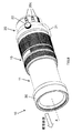
また、レンズ鏡筒10は、図1A等に示すように、被写体側の先端部分に、レンズフード30が被写体側へ繰り出し可能な状態で取り付けられている。さらに、レンズ鏡筒10は、図1Aおよび図1Bに示すように、内蔵する光学系が広角側(WIDE位置)と望遠側(TELE位置)との間において移動することで、倍率を変えて撮影を行うことができる。
Further, as shown in FIG. 1A and the like, the lens barrel 10 is attached to the tip portion on the subject side so that the lens hood 30 can be extended to the subject side. Further, as shown in FIGS. 1A and 1B, the lens barrel 10 is photographed at a different magnification by moving the built-in optical system between the wide angle side (WIDE position) and the telephoto side (TELE position). It can be performed.
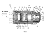
レンズ鏡筒10は、図1Aに示すWIDE位置にある状態では、図2Aに示すように、1群ユニット11が外装ユニット19の内周面側に収納された状態となる。
When the lens barrel 10 is in the WIDE position shown in FIG. 1A, the first group unit 11 is housed on the inner peripheral surface side of the exterior unit 19 as shown in FIG. 2A.
一方、レンズ鏡筒10は、図1Bに示すTELE位置にある状態では、図2Bに示すように、1群ユニット11が光軸X方向に沿って被写体側へ進出し、外装ユニット19から被写体寄りに突出した状態となる。
On the other hand, in the state where the lens barrel 10 is in the TELE position shown in FIG. 1B, as shown in FIG. 2B, the first group unit 11 advances to the subject side along the optical axis X direction, and moves away from the exterior unit 19 toward the subject. It will be in the state of protruding.
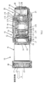
そして、レンズ鏡筒10は、図3に示すように、1群ユニット11、2群ユニット12、カム枠13、固定枠14、3群ユニット15、4群ユニット16、5群ユニット17、マウントベース18、外装ユニット(前枠)19、後枠20、複数のレンズL1~L18を含む光学系、を備えている。
As shown in FIG. 3, the lens barrel 10 includes a first group unit 11, a second group unit 12, a cam frame 13, a fixed frame 14, a third group unit 15, a fourth group unit 16, a fifth group unit 17, and a mount base. 18, an exterior unit (front frame) 19, a rear frame 20, and an optical system including a plurality of lenses L 1 to L 18.
1群ユニット11は、図3に示すように、レンズ鏡筒10における最も被写体側へ配置された筒状の部材である。1群ユニット11は、図2Aおよび図2B等に示すように、被写体側においてレンズL1~L3を保持した状態で、光軸X方向に沿って前進または後退する。これにより、レンズL1~L18の間の距離を変化させることで、光学系の倍率を変えることができる。すなわち、広角撮影や望遠撮影等を行うことができる。
As shown in FIG. 3, the first group unit 11 is a cylindrical member arranged on the most object side in the lens barrel 10. As shown in FIGS. 2A and 2B, the first group unit 11 moves forward or backward along the optical axis X direction while holding the lenses L1 to L3 on the subject side. Thus, the magnification of the optical system can be changed by changing the distance between the lenses L1 to L18. That is, wide-angle photography, telephoto photography, etc. can be performed.
また、本実施形態の1群ユニット11は、被写体側の先端部分に設けられており、撮影時の不要光の入射を抑制するレンズフード30を有している。
In addition, the first group unit 11 of the present embodiment is provided at the distal end portion on the subject side, and has a lens hood 30 that suppresses the incidence of unnecessary light during photographing.
レンズフード30は、図3に示すように、円筒状の部材である。レンズフード30は、使用時には、光軸X方向に沿って被写体側へ繰り出し可能な状態で取り付けられている。
The lens hood 30 is a cylindrical member as shown in FIG. The lens hood 30 is attached in a state where the lens hood 30 can be extended to the subject side along the optical axis X direction when in use.
2群ユニット12は、図2Aおよび図2B等に示すように、1群ユニット11の内周面側に配置された円筒状の部材であって、レンズL4~L9を保持している。
As shown in FIGS. 2A and 2B, the second group unit 12 is a cylindrical member disposed on the inner peripheral surface side of the first group unit 11, and holds lenses L4 to L9.
カム枠13は、図3に示すように、円筒状の部材であって、4群ユニット16の外周面側に配置されている。そして、カム枠13には、4群ユニット16の外周面に設けられたカムピン(図示せず)が嵌合するカム溝が形成されている。カム枠13は、使用者により回転操作されるズームリングと係合されている。カム枠13は、ズームリングの回転に伴い、回転駆動される。
As shown in FIG. 3, the cam frame 13 is a cylindrical member and is disposed on the outer peripheral surface side of the fourth group unit 16. The cam frame 13 is formed with a cam groove into which a cam pin (not shown) provided on the outer peripheral surface of the fourth group unit 16 is fitted. The cam frame 13 is engaged with a zoom ring that is rotated by a user. The cam frame 13 is driven to rotate as the zoom ring rotates.
カム枠13が回転すると、カム溝に沿ってカムピンが移動する。これにより、カム枠13を回転させることにより、1群ユニット11から5群ユニット17の光軸X方向における位置を調整できる。よって、1群ユニット11から5群ユニット17に含まれるレンズL1~L18間の距離を調整して、広角撮影や望遠撮影等を行うことができる。
When the cam frame 13 rotates, the cam pin moves along the cam groove. Thereby, by rotating the cam frame 13, the position of the first group unit 11 to the fifth group unit 17 in the optical axis X direction can be adjusted. Therefore, wide-angle shooting, telephoto shooting, and the like can be performed by adjusting the distance between the lenses L1 to L18 included in the first group unit 11 to the fifth group unit 17.
固定枠14は、図3に示すように、円筒状の2群ユニット12および4群ユニット16の外周側に配置された円筒状の部材である。固定枠14は、2群ユニット12から4群ユニット16の外周面を覆うように配置されている。
The fixed frame 14 is a cylindrical member arranged on the outer peripheral side of the cylindrical second group unit 12 and the fourth group unit 16 as shown in FIG. The fixed frame 14 is disposed so as to cover the outer peripheral surfaces of the second group unit 12 to the fourth group unit 16.
3群ユニット15は、図3に示すように、円筒状の4群ユニット16の内周側に、光軸X方向において移動可能な状態で配置されている。3群ユニット15は、図2A、図2Bに示すように、レンズL10~L15を保持している。そして、3群ユニット15は、カム枠13の回転に伴い、光軸X方向に移動する。
As shown in FIG. 3, the third group unit 15 is arranged on the inner peripheral side of the cylindrical fourth group unit 16 in a movable state in the optical axis X direction. As shown in FIGS. 2A and 2B, the third group unit 15 holds lenses L10 to L15. The third group unit 15 moves in the optical axis X direction as the cam frame 13 rotates.
4群ユニット16は、略円筒状であり、4群ユニット16は、レンズL16を保持している。4群ユニット16は、図3に示すように、光軸X方向における被写体側から見て、3群ユニット15の下流側に配置されている。4群ユニット16は、カム枠13の回転に伴い、光軸X方向に移動する。オートフォーカス用のアクチュエータは、4群ユニット16のレンズL16を、カム枠13に対して相対的に光軸X方向に移動させる。
The fourth group unit 16 has a substantially cylindrical shape, and the fourth group unit 16 holds a lens L16. As shown in FIG. 3, the fourth group unit 16 is disposed on the downstream side of the third group unit 15 when viewed from the subject side in the optical axis X direction. The fourth group unit 16 moves in the optical axis X direction as the cam frame 13 rotates. The autofocus actuator moves the lens L16 of the fourth group unit 16 relative to the cam frame 13 in the optical axis X direction.
5群ユニット17は、図3に示すように、円筒状の4群ユニット16の内周側に、光軸X方向において移動可能な状態で配置されている。5群ユニット17は、図2A、図2Bに示すように、レンズL17,L18を保持している。そして、5群ユニット17は、カム枠13の回転に伴い、光軸X方向に移動する。
As shown in FIG. 3, the fifth group unit 17 is arranged on the inner peripheral side of the cylindrical fourth group unit 16 so as to be movable in the optical axis X direction. As shown in FIGS. 2A and 2B, the fifth group unit 17 holds lenses L17 and L18. The fifth group unit 17 moves in the direction of the optical axis X as the cam frame 13 rotates.
マウントベース18は、図3に示すように、レンズ鏡筒10のベースとなる略円筒状の部材である。マウントベース18には、相対的に回転可能な状態でカム枠13が取り付けられる。4群ユニットは、カム枠13と固定枠14の内周に保持されている。
The mount base 18 is a substantially cylindrical member serving as a base of the lens barrel 10 as shown in FIG. The cam frame 13 is attached to the mount base 18 in a relatively rotatable state. The fourth group unit is held on the inner periphery of the cam frame 13 and the fixed frame 14.
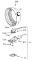
外装ユニット(前枠)19は、図1Aおよび図4等に示すように、レンズ鏡筒10の外装部分(外周面)を構成する円筒状の部材である。外装ユニット19外周面には、円環状のフォーカスリングやズームリング等が回転可能な状態で取り付けられている。
The exterior unit (front frame) 19 is a cylindrical member constituting the exterior part (outer peripheral surface) of the lens barrel 10 as shown in FIGS. 1A and 4. An annular focus ring, zoom ring or the like is attached to the outer peripheral surface of the exterior unit 19 in a rotatable state.
後枠20は、外装ユニット19の被写体とは反対側の端部に取り付けられている。後枠20と外装ユニット19とは、ともにレンズ鏡筒10の外装部分を構成する。そして、後枠20は、マウントベース18、および、外装ユニット19に対して相対的に回転可能な状態で取り付けられている。
The rear frame 20 is attached to the end of the exterior unit 19 opposite to the subject. The rear frame 20 and the exterior unit 19 together constitute an exterior portion of the lens barrel 10. The rear frame 20 is attached so as to be rotatable relative to the mount base 18 and the exterior unit 19.
また、後枠20は、外周面に使用者が操作するためのスイッチ部材20cを有する。後枠は、回路基板25(図2B等参照)と、スイッチフレキ(フレキシブル基板)24(図5等参照)とを内包している。回路基板25は、使用者によるスイッチ部材20cの操作を検出する。スイッチフレキ24は、回路基板25に電気的に接続されている。さらに、後枠20は、図4に示すように、三脚ベースリング20aと、スイッチユニット枠20bとを有している。
Also, the rear frame 20 has a switch member 20c for the user to operate on the outer peripheral surface. The rear frame includes a circuit board 25 (see FIG. 2B and the like) and a switch flexible (flexible board) 24 (see FIG. 5 and the like). The circuit board 25 detects the operation of the switch member 20c by the user. The switch flexible 24 is electrically connected to the circuit board 25. Further, as shown in FIG. 4, the rear frame 20 has a tripod base ring 20a and a switch unit frame 20b.
三脚ベースリング20aには、図4に示すように、外周部分に、三脚を接続するための三脚座21が取り付けられる。また、三脚ベースリング20aは、図5に示すように、マウントベース18における被写体とは反対側の端部に、三脚補強リング23を介して取り付けられている。
As shown in FIG. 4, a tripod base 21 for connecting a tripod is attached to the tripod base ring 20a. Further, as shown in FIG. 5, the tripod base ring 20 a is attached to the end of the mount base 18 opposite to the subject via a tripod reinforcing ring 23.
取付部20aaは、図4に示すように、三脚ベースリング20aの外周面から内周面側へ貫通するように形成された開口部である。三脚座21は、取付部20aaに取り付けられる。
The mounting portion 20aa is an opening formed so as to penetrate from the outer peripheral surface of the tripod base ring 20a to the inner peripheral surface side, as shown in FIG. The tripod seat 21 is attached to the attachment portion 20aa.
スイッチユニット枠20bは、図4に示すように、三脚ベースリング20aの被写体とは反対側の端部に取り付けられる円筒状の部材である。なお、スイッチユニット枠20bは、図5に示すように、図示しない複数のねじを用いて、三脚ベースリング20aに固定される。そして、スイッチユニット枠20bは、オートフォーカス(AF)とマニュアルフォーカス(MF)とを切り替えるスイッチを含む各種スイッチ(スイッチ部材20c)が外周面に設けられている。
As shown in FIG. 4, the switch unit frame 20b is a cylindrical member attached to the end of the tripod base ring 20a opposite to the subject. As shown in FIG. 5, the switch unit frame 20b is fixed to the tripod base ring 20a using a plurality of screws (not shown). The switch unit frame 20b is provided with various switches (switch member 20c) including switches for switching between auto focus (AF) and manual focus (MF) on the outer peripheral surface.
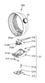
三脚座21は、図示しない三脚が接続される台座である。三脚座21は、レンズ鏡筒10の外装部分を構成する三脚ベースリング20aの外周面に取り付けられる。そして、三脚座21は、図6に示すように、三脚ねじ21a、ねじ21b、三脚ベース21c、ねじ21d、ねじ21e、カバー21fを有している。
The tripod base 21 is a pedestal to which a tripod (not shown) is connected. The tripod seat 21 is attached to the outer peripheral surface of the tripod base ring 20 a that constitutes the exterior portion of the lens barrel 10. As shown in FIG. 6, the tripod seat 21 has a tripod screw 21a, a screw 21b, a tripod base 21c, a screw 21d, a screw 21e, and a cover 21f.
三脚ねじ21aは、三脚側の雄ねじ部分が螺合する金属製の部材である。これにより、三脚座21に対して三脚が固定される。三脚ねじ21aは、図6に示すように、円柱部21aa、ねじ部21abを有している。
The tripod screw 21a is a metal member with which the male screw portion on the tripod side is screwed. Thereby, the tripod is fixed to the tripod seat 21. As shown in FIG. 6, the tripod screw 21a has a cylindrical portion 21aa and a screw portion 21ab.
円柱部21aaは、三脚ベースリング20aに形成された開口部(取付部20aa)に対して挿入された状態で取り付けられる。
The cylindrical part 21aa is attached in a state of being inserted into the opening part (attachment part 20aa) formed in the tripod base ring 20a.
ねじ部21abは、三脚側の雄ねじ部分が螺合する雌ねじ部分である。ねじ部21abは、図6に示すように、三脚ねじ21aにおいて、円柱部21aaの反対側の面に形成されている。
The screw portion 21ab is a female screw portion into which a male screw portion on the tripod side is screwed. As shown in FIG. 6, the screw portion 21ab is formed on the surface of the tripod screw 21a on the opposite side of the cylindrical portion 21aa.
ねじ21bは、図6に示すように、三脚ねじ21aを三脚ベース21cに対して固定するために用いられる。
As shown in FIG. 6, the screw 21b is used to fix the tripod screw 21a to the tripod base 21c.
三脚ベース21cは、図6に示すように、三脚ベースリング20aに取り付けられる。三脚ベース21cは、ねじ21dおよびねじ21eを用いて、4箇所から三脚ベースリング20aの外周面に固定される。三脚ベース21cには、三脚ねじ21aが取り付けられる。これにより、三脚ベースリング20aは、三脚ねじ21aに対して固定される。すなわち、三脚ねじ21aに三脚が取り付けられている状態において、三脚ベースリング20aは、三脚に対して固定されている。
The tripod base 21c is attached to a tripod base ring 20a as shown in FIG. The tripod base 21c is fixed to the outer peripheral surface of the tripod base ring 20a from four locations using screws 21d and 21e. A tripod screw 21a is attached to the tripod base 21c. Thereby, the tripod base ring 20a is fixed to the tripod screw 21a. That is, in the state where the tripod is attached to the tripod screw 21a, the tripod base ring 20a is fixed to the tripod.
カバー21fは、図6に示すように、三脚ベース21cにおける三脚が接続される側(図6中下側)の面を構成する樹脂製の板状部材である。カバー21fには、ねじ21eを挿入するためのねじ穴が形成されている。なお、板状部材は金属製であってもよい。
As shown in FIG. 6, the cover 21 f is a resin plate-like member that constitutes a surface (a lower side in FIG. 6) to which the tripod base 21 c is connected. A screw hole for inserting the screw 21e is formed in the cover 21f. The plate member may be made of metal.
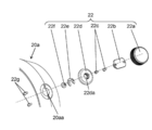
三脚ロックねじ(固定部材)22は、図6等に示すように、三脚ベースリング20aの外周面に取り付けられている。三脚ロックねじ22が解放状態のとき、後枠20は、外装ユニット19(前枠)に対して相対的に回転可能である。三脚ロックねじ22が固定状態のとき、三脚ロックねじ22は、後枠20と外装ユニット19との相対回転を規制する。これにより、後枠20と外装ユニット19の相対回転を任意の回転位置で固定することができる。具体的には、三脚ロックねじ22は、図7および図8に示すように、回転つまみ22a、ロックねじ22b、ねじ22c、ねじベース22d、止め具22e、押さえピン22f、およびねじ22gを有している。この構成により、三脚ロックねじ22は、光軸Xに交差する方向に押圧力を付与し、後枠20の外装ユニット19に対する相対的な回転を規制することができる。
The tripod lock screw (fixing member) 22 is attached to the outer peripheral surface of the tripod base ring 20a as shown in FIG. When the tripod lock screw 22 is in the released state, the rear frame 20 is rotatable relative to the exterior unit 19 (front frame). When the tripod lock screw 22 is in a fixed state, the tripod lock screw 22 restricts relative rotation between the rear frame 20 and the exterior unit 19. Thereby, the relative rotation of the rear frame 20 and the exterior unit 19 can be fixed at an arbitrary rotational position. Specifically, as shown in FIGS. 7 and 8, the tripod lock screw 22 has a rotary knob 22a, a lock screw 22b, a screw 22c, a screw base 22d, a stopper 22e, a pressing pin 22f, and a screw 22g. ing. With this configuration, the tripod lock screw 22 can apply a pressing force in a direction crossing the optical axis X, and can restrict relative rotation of the rear frame 20 with respect to the exterior unit 19.
回転つまみ22aは、三脚ロックねじ22の外装面を構成する回転つまみ部材であって、使用者の指によって回転操作される。
The rotary knob 22a is a rotary knob member that forms the exterior surface of the tripod lock screw 22, and is rotated by a user's finger.
ロックねじ22bは、図8に示すように、三脚ベースリング20aに取り付けられるための雄ねじ部22baを有している。そして、ロックねじ22bは、図7および図8に示すように、2本のねじ22cを用いて、回転つまみ22aの裏面側へ固定される。
As shown in FIG. 8, the lock screw 22b has a male screw portion 22ba to be attached to the tripod base ring 20a. Then, as shown in FIGS. 7 and 8, the lock screw 22b is fixed to the back surface side of the rotary knob 22a using two screws 22c.
ねじベース22dは、図7および図8に示すように、ロックねじ22bの雄ねじ部22baが螺合する雌ねじ部22daを有している。雌ねじ部22daに雄ねじ部22baが螺合することにより、ねじベース22dと回転つまみ22aとは、回転可能な状態で取り付けられる。また、ねじベース22dは、図7および図8に示すように、2本のねじ22gを用いて、三脚ベースリング20aの外周面に固定される。
As shown in FIGS. 7 and 8, the screw base 22d has a female screw portion 22da into which the male screw portion 22ba of the lock screw 22b is screwed. When the male screw portion 22ba is screwed into the female screw portion 22da, the screw base 22d and the rotary knob 22a are attached in a rotatable state. Further, as shown in FIGS. 7 and 8, the screw base 22d is fixed to the outer peripheral surface of the tripod base ring 20a using two screws 22g.
止め具22eは、図7および図8に示すように、ねじベース22dと取付部20aaとの間に挟みこまれるように配置されている。止め具22eは、雄ねじ部22baの回転範囲を規制する。これにより、止め具22eは、雄ねじ部22baが雌ねじ部22daに螺合した状態から外れてしまうことを防止する。
As shown in FIGS. 7 and 8, the stopper 22e is disposed so as to be sandwiched between the screw base 22d and the attachment portion 20aa. The stopper 22e restricts the rotation range of the male screw portion 22ba. Accordingly, the stopper 22e prevents the male screw portion 22ba from being detached from the state where the male screw portion 22ba is screwed to the female screw portion 22da.
押さえピン22fは、ロックねじ22bの雄ねじ部22baの先端部分に固定されている。回転つまみ22aが回転操作されたとき、押さえピン22fは、径方向に移動する。三脚ロックねじ22の固定状態は、押さえピン22fが押し込む方向に移動した状態、すなわち、押さえピン22fが三脚ベースリング20aの取付部20aaの開口から内周面側(径方向内側)へ突出した状態である。これにより、三脚ロックねじ22が固定状態のとき、押さえピン22fは、三脚ベースリング20aの内周面側へ配置された部材(三脚補強リング23)に対して押圧力を加えることができる。
The holding pin 22f is fixed to the tip portion of the male screw portion 22ba of the lock screw 22b. When the rotary knob 22a is rotated, the pressing pin 22f moves in the radial direction. The fixed state of the tripod lock screw 22 is a state in which the pressing pin 22f is moved in the pushing direction, that is, a state in which the pressing pin 22f protrudes from the opening of the mounting portion 20aa of the tripod base ring 20a to the inner peripheral surface side (inward in the radial direction). It is. Thereby, when the tripod lock screw 22 is in a fixed state, the pressing pin 22f can apply a pressing force to the member (tripod reinforcing ring 23) disposed on the inner peripheral surface side of the tripod base ring 20a.
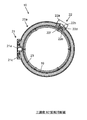
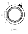
三脚補強リング23は、図9および図10に示すように、三脚ロックねじ22の押さえピン22fの内周側に配置された金属製(アルミ材(A5052)、ステンレス鋼材(SUS)等)のリング状部材である。三脚ロックねじ22が回転操作されて三脚ベースリング20aの内周側(径方向内側)へ押し込まれると、押さえピン22fは、三脚補強リング23の外周面に押圧力を加える。これにより、押さえピン22fと三脚補強リング23との間に摩擦力が生じる。三脚補強リング23は、内周側に配置された部材(外装ユニット19の後端部)に対して、ビスにより固定されている。これにより、後枠20に対する外装ユニット19の回転を規制することができる。
As shown in FIGS. 9 and 10, the tripod reinforcement ring 23 is a metal ring (aluminum (A5052), stainless steel (SUS), etc.) disposed on the inner peripheral side of the holding pin 22f of the tripod lock screw 22. It is a shaped member. When the tripod lock screw 22 is rotated and pushed into the inner peripheral side (inward in the radial direction) of the tripod base ring 20 a, the pressing pin 22 f applies a pressing force to the outer peripheral surface of the tripod reinforcing ring 23. Thereby, a frictional force is generated between the pressing pin 22f and the tripod reinforcing ring 23. The tripod reinforcing ring 23 is fixed to a member (rear end portion of the exterior unit 19) disposed on the inner peripheral side with screws. Thereby, rotation of the exterior unit 19 with respect to the rear frame 20 can be regulated.
このとき、押さえピン22fが加える押圧力が外装ユニット19に加わると、外装ユニット19の後端部が変形する恐れがある。三脚補強リング23は、外装ユニット19よりも剛性が高いことにより、押さえピン22fが加える押圧力を分散させることができる。これにより、押さえピン22fが加える押圧力による外装ユニット19の後端部の変形を防ぐことができる。
At this time, if the pressing force applied by the pressing pin 22f is applied to the exterior unit 19, the rear end portion of the exterior unit 19 may be deformed. Since the tripod reinforcing ring 23 has higher rigidity than the exterior unit 19, the pressing force applied by the pressing pin 22f can be dispersed. Thereby, the deformation | transformation of the rear-end part of the exterior unit 19 by the pressing force which the press pin 22f applies can be prevented.
以上のように、後枠20に対する外装ユニット19の回転を規制することにより、マウントベース18(カメラ本体50)に対する後枠20の回転を規制することができる。この結果、三脚座21に対するカメラ本体50の回転位置を所望の回転位置において固定することができる。すなわち、レンズ鏡筒10を三脚に固定した状態で、カメラ100の撮影姿勢を変更し、その撮影姿勢を保持することができる。
As described above, by restricting the rotation of the exterior unit 19 relative to the rear frame 20, the rotation of the rear frame 20 relative to the mount base 18 (camera body 50) can be restricted. As a result, the rotation position of the camera body 50 with respect to the tripod seat 21 can be fixed at a desired rotation position. That is, with the lens barrel 10 fixed to a tripod, the shooting posture of the camera 100 can be changed and the shooting posture can be maintained.
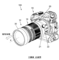
カメラ本体50が被写体に対して正姿勢の状態で三脚を用いた撮影を行う場合、図11に示すように、三脚座21の回転位置は、カメラ本体50の底面の回転位置と同じである。このため、図11に示す正姿勢で撮影を行う場合には、図9に示す回転位置において三脚ロックねじ22を時計回りに回転させて固定状態とし、後枠20の回転を規制する。
When the camera body 50 performs shooting using a tripod in a normal posture with respect to the subject, the rotation position of the tripod seat 21 is the same as the rotation position of the bottom surface of the camera body 50 as shown in FIG. For this reason, when photographing in the normal posture shown in FIG. 11, the tripod lock screw 22 is rotated clockwise in the rotational position shown in FIG.
これにより、正姿勢における三脚座21とカメラ本体50との相対的な回転位置を保持することができる。すなわち、撮影時にカメラ本体50が回転してしまうことを防止しつつ、撮影を実施することができる。
Thereby, the relative rotational position of the tripod base 21 and the camera body 50 in the normal posture can be maintained. That is, shooting can be performed while preventing the camera body 50 from rotating during shooting.
一方、図12に示すように、カメラ本体50を被写体に対して90度回転させた状態で三脚を用いた撮影を行う場合、三脚座21は、カメラ本体50の底面に対して90度の位置になるように回転させた位置で固定する。図12に示す回転姿勢(90度回転姿勢)で撮影を行う場合には、図10に示す回転位置において三脚ロックねじ22を時計回りに回転させて固定状態とし、後枠20の回転を規制する。
On the other hand, as shown in FIG. 12, when shooting using a tripod with the camera body 50 rotated 90 degrees with respect to the subject, the tripod seat 21 is positioned 90 degrees with respect to the bottom surface of the camera body 50. Fix it at the position where it is rotated. When shooting is performed in the rotational posture shown in FIG. 12 (90-degree rotational posture), the tripod lock screw 22 is rotated clockwise in the rotational position shown in FIG. 10 to be in a fixed state, and the rotation of the rear frame 20 is restricted. .
これにより、90度回転姿勢における三脚座21とカメラ本体50との相対的な回転位置を保持することができる。すなわち、撮影時にカメラ本体50が回転してしまうことを防止しつつ、撮影を実施することができる。
Thereby, the relative rotational position of the tripod base 21 and the camera body 50 in the 90-degree rotational posture can be maintained. That is, shooting can be performed while preventing the camera body 50 from rotating during shooting.
なお、カメラ本体50の底面とは、シャッターやストロボが装着された正姿勢におけるカメラ本体50の上部とは反対側の面である。
Note that the bottom surface of the camera body 50 is the surface opposite to the upper part of the camera body 50 in a normal posture with a shutter and strobe attached.
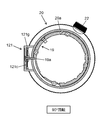
スイッチフレキ(フレキシブル基板)24は、後枠20の被写体とは反対側を構成するスイッチユニット枠20bの各種スイッチと回路基板25(図2A等参照)とを電気的に接続するフレキシブル基板である。スイッチフレキ24は、図5に示すように、スイッチユニット枠20bの内周面に沿って配置されている。
The switch flexible (flexible substrate) 24 is a flexible substrate that electrically connects various switches of the switch unit frame 20b constituting the side opposite to the subject of the rear frame 20 and the circuit board 25 (see FIG. 2A and the like). As shown in FIG. 5, the switch flexible 24 is arranged along the inner peripheral surface of the switch unit frame 20b.
本実施形態のレンズ鏡筒10では、上述したように、三脚座21が取り付けられた後枠20は、マウントベース18に対して回転可能である。このとき、スイッチフレキ24の一方の端子が接続された回路基板25は、マウントベース18側の部材に固定されている。一方、スイッチフレキ24の他方の端子が接続された各種スイッチはスイッチユニット枠20bとともに回転する。
In the lens barrel 10 of the present embodiment, as described above, the rear frame 20 to which the tripod seat 21 is attached is rotatable with respect to the mount base 18. At this time, the circuit board 25 to which one terminal of the switch flexible 24 is connected is fixed to a member on the mount base 18 side. On the other hand, the various switches to which the other terminal of the switch flexible 24 is connected rotate together with the switch unit frame 20b.
このため、スイッチフレキ24は、図11に示す正姿勢と図12に示す90度回転姿勢において、スイッチユニット枠20bの内周面側において、屈曲した状態で配置される。
For this reason, the switch flexible 24 is disposed in a bent state on the inner peripheral surface side of the switch unit frame 20b in the normal posture shown in FIG. 11 and the 90-degree rotated posture shown in FIG.
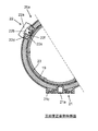
具体的には、カメラ100が図11に示す正姿勢の状態では、スイッチフレキ24は、図13Aに示すように、スイッチユニット枠20bの内周面に沿って、長手方向におけるほぼ中央において折り曲げられた状態となる。
Specifically, when the camera 100 is in the normal posture shown in FIG. 11, the switch flexible 24 is bent at substantially the center in the longitudinal direction along the inner peripheral surface of the switch unit frame 20 b as shown in FIG. 13A. It becomes a state.
一方、カメラ100が図12に示す90度の回転姿勢の状態では、スイッチフレキ24は、図13Bに示すように、スイッチユニット枠20bの内周面に沿って、長手方向における一方の端部近傍において折り曲げられた状態となる。
On the other hand, in the state in which the camera 100 is rotated 90 degrees as shown in FIG. 12, the switch flexible 24 is near one end in the longitudinal direction along the inner peripheral surface of the switch unit frame 20b as shown in FIG. 13B. In a bent state.
これにより、三脚が接続された状態でカメラ100の姿勢を変更した場合でも、三脚座21が取り付けられた後枠20の回転に追従してスイッチフレキ24が屈曲度を変更する。この結果、後枠20を回転させた場合でも、スイッチユニット枠20bの各種スイッチ類と、回路基板25との電気的接続を確保することができる。
Thus, even when the posture of the camera 100 is changed with the tripod connected, the switch flexible 24 changes the bending degree following the rotation of the rear frame 20 to which the tripod seat 21 is attached. As a result, even when the rear frame 20 is rotated, the electrical connection between the various switches of the switch unit frame 20b and the circuit board 25 can be ensured.
これにより、後枠20にスイッチ部材20cを設けつつ、外装ユニット(前枠)19を後枠20に対して相対的に回転可能とすることができる。後枠20にスイッチ部材20cを設けることにより、カメラ本体50の撮影姿勢を回転させたとしても、三脚に対するスイッチ部材20cの位置が変わらない。これにより、カメラ本体50の姿勢が正姿勢のときと90度回転姿勢のときとで、各種スイッチの操作位置を一定にすることができる。
This makes it possible to rotate the exterior unit (front frame) 19 relative to the rear frame 20 while providing the switch member 20 c on the rear frame 20. By providing the switch member 20c on the rear frame 20, the position of the switch member 20c with respect to the tripod does not change even if the photographing posture of the camera body 50 is rotated. Thereby, the operation positions of the various switches can be made constant between when the camera body 50 is in the normal posture and when it is in the 90 ° rotation posture.
次に、図11に示すように、カメラ100の撮影姿勢が正姿勢にある状態と、図12に示すカメラ100を90度回転させた状態とに、容易に位置決め可能になる構成について説明する。
Next, as shown in FIG. 11, a configuration in which the camera 100 can be easily positioned in a state where the photographing posture of the camera 100 is in a normal posture and a state where the camera 100 shown in FIG. 12 is rotated by 90 degrees will be described.
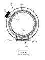
本構成においては、三脚座121には、図14に示すように、係止ピン121gと、固定ねじ121hとが設けられている。係止ピン121gは、三脚ベース121cを貫通する貫通孔に挿入されている。固定ねじ121hは、係止ピン121gを径方向において進退させる。図15Aおよび図15Bに示すように、外装ユニット19には、段差である当接部19aが2箇所に形成されている。ここでは、2つの段差は円周上で中心角が90度となる位置に形成されている。後枠20の回転に伴って三脚座121が移動するとき、所定の位置で係止ピン121gが当接部19aに当たることで後枠20の回転範囲が規制される。後枠20の回転範囲の両端においては、三脚座121の係止ピン121gが外装ユニット19の当接部19aに当たった状態となる。この状態で三脚ロックねじ22を回転させて後枠20の回転を規制することで、外装ユニット19と後枠20とを所定の回転位置において固定することができる。このような構成により、係止ピン121gおよび当接部19aによって、後枠20を、正姿勢および90度回転姿勢での回転位置に容易に固定することができる。
In this configuration, the tripod seat 121 is provided with a locking pin 121g and a fixing screw 121h as shown in FIG. The locking pin 121g is inserted into a through hole that penetrates the tripod base 121c. The fixing screw 121h advances and retracts the locking pin 121g in the radial direction. As shown in FIGS. 15A and 15B, the exterior unit 19 has two contact portions 19a that are steps. Here, the two steps are formed at positions on the circumference where the central angle is 90 degrees. When the tripod seat 121 moves with the rotation of the rear frame 20, the rotation range of the rear frame 20 is restricted by the locking pin 121g hitting the contact portion 19a at a predetermined position. At both ends of the rotation range of the rear frame 20, the locking pins 121 g of the tripod seat 121 are in contact with the contact portions 19 a of the exterior unit 19. By rotating the tripod lock screw 22 in this state to restrict the rotation of the rear frame 20, the exterior unit 19 and the rear frame 20 can be fixed at a predetermined rotational position. With such a configuration, the rear frame 20 can be easily fixed at the rotation position in the normal posture and the 90-degree rotation posture by the locking pin 121g and the contact portion 19a.
[他の実施形態]
以上、本開示の一実施形態について説明したが、本開示は上記実施形態に限定されるものではなく、開示の要旨を逸脱しない範囲で種々の変更が可能である。 [Other Embodiments]
Although one embodiment of the present disclosure has been described above, the present disclosure is not limited to the above-described embodiment, and various modifications can be made without departing from the scope of the disclosure.
(A)
上記実施形態では、図4に示すように、三脚座21が取り付けられた後枠20が、三脚ベースリング20aとスイッチユニット枠20bとに分割される例を挙げて説明した。しかし、本開示はこれに限定されるものではない。 (A)
In the above embodiment, as illustrated in FIG. 4, therear frame 20 to which the tripod seat 21 is attached has been described with an example in which the rear frame 20 is divided into the tripod base ring 20a and the switch unit frame 20b. However, the present disclosure is not limited to this.
上記実施形態では、図4に示すように、三脚座21が取り付けられた後枠20が、三脚ベースリング20aとスイッチユニット枠20bとに分割される例を挙げて説明した。しかし、本開示はこれに限定されるものではない。 (A)
In the above embodiment, as illustrated in FIG. 4, the
例えば、三脚ベースリング20aの部分とスイッチユニット枠20bの部分とが分割不能であって一体化された後枠に、三脚座を設けてもよい。
For example, a tripod seat may be provided on the rear frame in which the tripod base ring 20a portion and the switch unit frame 20b portion cannot be divided and are integrated.
(B)
上記実施形態では、図4等に示すように、レンズ鏡筒10の外装部分の一部を構成する後枠20に、三脚座21を取り付けた例を挙げて説明した。しかし、本開示はこれに限定されるものではない。 (B)
In the above embodiment, as shown in FIG. 4 and the like, an example in which atripod seat 21 is attached to the rear frame 20 constituting a part of the exterior portion of the lens barrel 10 has been described. However, the present disclosure is not limited to this.
上記実施形態では、図4等に示すように、レンズ鏡筒10の外装部分の一部を構成する後枠20に、三脚座21を取り付けた例を挙げて説明した。しかし、本開示はこれに限定されるものではない。 (B)
In the above embodiment, as shown in FIG. 4 and the like, an example in which a
例えば、カメラ本体へ取り付けられるマウントベースに対して回転可能な状態で取り付けられた回転部材であれば、他の外装部分へ三脚座が取り付けられたレンズ鏡筒であってもよい。
For example, as long as it is a rotating member attached to a mount base attached to the camera body in a rotatable state, a lens barrel having a tripod seat attached to another exterior part may be used.
(C)
上記実施形態では、図6に示すように、三脚座21が、後枠20(三脚ベースリング20a)の外周面に対して、複数のねじ21d,21eを用いて取り付けられる例を挙げて説明した。しかし、本開示はこれに限定されるものではない。 (C)
In the said embodiment, as shown in FIG. 6, thetripod seat 21 demonstrated and demonstrated the example attached with respect to the outer peripheral surface of the rear frame 20 (tripod base ring 20a) using several screws 21d and 21e. . However, the present disclosure is not limited to this.
上記実施形態では、図6に示すように、三脚座21が、後枠20(三脚ベースリング20a)の外周面に対して、複数のねじ21d,21eを用いて取り付けられる例を挙げて説明した。しかし、本開示はこれに限定されるものではない。 (C)
In the said embodiment, as shown in FIG. 6, the
例えば、三脚座が後枠と一体成形されたレンズ鏡筒であってもよい。
For example, a lens barrel in which the tripod mount is integrally formed with the rear frame may be used.
(D)
上記実施形態では、カメラ100が正姿勢(図11)と90度回転姿勢(図12)とにある状態で、後枠20の回転を規制するために、三脚ロックねじ22を回転操作する例を挙げて説明した。しかし、本開示はこれに限定されるものではない。 (D)
In the above embodiment, an example in which thetripod lock screw 22 is rotated in order to restrict the rotation of the rear frame 20 in a state where the camera 100 is in the normal posture (FIG. 11) and the 90-degree rotational posture (FIG. 12). I gave it as an explanation. However, the present disclosure is not limited to this.
上記実施形態では、カメラ100が正姿勢(図11)と90度回転姿勢(図12)とにある状態で、後枠20の回転を規制するために、三脚ロックねじ22を回転操作する例を挙げて説明した。しかし、本開示はこれに限定されるものではない。 (D)
In the above embodiment, an example in which the
例えば、三脚に固定されたカメラを被写体に対して45度傾けた状態で撮影する場合には、所望の回転角度の姿勢で後枠の回転を規制するように、三脚ロックねじを回転操作してもよい。
For example, when shooting with a camera fixed on a tripod tilted 45 degrees relative to the subject, rotate the tripod lock screw to regulate the rotation of the rear frame at the desired rotational angle. Also good.
すなわち、三脚ロックねじは、正姿勢と90度回転姿勢とに限らず、他のカメラ姿勢において回転操作されて、後枠の回転を規制してもよい。
That is, the tripod lock screw is not limited to the normal posture and the 90-degree rotation posture, and may be rotated in another camera posture to restrict the rotation of the rear frame.
(E)
上記実施形態では、所望の姿勢において後枠20の回転を規制して後枠20を固定する際に、内周側(径方向内側)に向かって押圧力を加えるために、三脚ロックねじ22を回転操作する例を挙げて説明した。しかし、本開示はこれに限定されるものではない。 (E)
In the above-described embodiment, when therear frame 20 is fixed by restricting the rotation of the rear frame 20 in a desired posture, the tripod lock screw 22 is used to apply a pressing force toward the inner peripheral side (inside in the radial direction). An example of rotating operation has been described. However, the present disclosure is not limited to this.
上記実施形態では、所望の姿勢において後枠20の回転を規制して後枠20を固定する際に、内周側(径方向内側)に向かって押圧力を加えるために、三脚ロックねじ22を回転操作する例を挙げて説明した。しかし、本開示はこれに限定されるものではない。 (E)
In the above-described embodiment, when the
例えば、三脚ロックねじ等の固定部材としては、回転操作されるものに限定されるものではなく、押し込み式の部材を用いてよい。
For example, the fixing member such as a tripod lock screw is not limited to one that is operated to rotate, and a push-in member may be used.
この場合には、所望の姿勢において後枠20の回転を規制して固定するために、所望の回転位置において固定部材を押し込むことで、内周面側へ押圧力を付与することができる。この結果、上記実施形態と同様の効果を得ることができる。
In this case, in order to restrict and fix the rotation of the rear frame 20 in a desired posture, a pressing force can be applied to the inner peripheral surface side by pushing the fixing member at a desired rotation position. As a result, the same effect as the above embodiment can be obtained.
一方で、押圧力を加える構成によれば、後枠の回転は摩擦力により規制される。これにより、カメラ100に加わる振動等により後枠の回転位置がぐらつくことを防止できる。
On the other hand, according to the configuration in which the pressing force is applied, the rotation of the rear frame is regulated by the frictional force. Thereby, it is possible to prevent the rotational position of the rear frame from wobbling due to vibration applied to the camera 100 or the like.
本開示のレンズ鏡筒は、リング式の回転三脚座を不要とし、小型化や部品点数の削減を図ることができるという効果を奏することから、三脚座を備えたレンズ鏡筒に対して広く適用可能である。
The lens barrel of the present disclosure eliminates the need for a ring-type rotary tripod seat, and can be reduced in size and reduced in the number of components. Therefore, the lens barrel of the present disclosure is widely applied to a lens barrel having a tripod seat. Is possible.
10 レンズ鏡筒
11 1群ユニット
12 2群ユニット
13 カム枠
14 固定枠
15 3群ユニット
16 4群ユニット
17 5群ユニット
18 マウントベース
19 外装ユニット(前枠)
19a 当接部
20 後枠
20a 三脚ベースリング
20aa 取付部
20b スイッチユニット枠
20c スイッチ部材
21 三脚座
21a 三脚ねじ
21aa 円柱部
21ab ねじ部
21b ねじ
21c 三脚ベース
21d ねじ
21e ねじ
21f カバー
22 三脚ロックねじ(固定部材)
22a 回転つまみ
22b ロックねじ
22ba 雄ねじ部
22c ねじ
22d ねじベース
22da 雌ねじ部
22e 止め具
22f 押さえピン
22g ねじ
23 三脚補強リング
24 スイッチフレキ(フレキシブル基板)
25 回路基板
30 レンズフード
50 カメラ本体
100 カメラ
121 三脚座
121c 三脚ベース
121g 係止ピン
121h 固定ねじ
L1~L18 レンズ 10lens barrel 11 first group unit 12 second group unit 13 cam frame 14 fixed frame 15 third group unit 16 fourth group unit 17 fifth group unit 18 mount base 19 exterior unit (front frame)
19a Contact part 20 Rear frame 20a Tripod base ring 20aa Mounting part 20b Switch unit frame 20c Switch member 21 Tripod seat 21a Tripod screw 21aa Column part 21ab Screw part 21b Screw 21c Tripod base 21d Screw 21e Screw 21f Cover 22 Tripod lock screw (fixed) Element)
22a Rotating knob 22b Lock screw 22ba Male thread part 22c Screw 22d Screw base 22da Female thread part 22e Stopper 22f Holding pin 22g Screw 23 Tripod reinforcement ring 24 Switch flexible (flexible substrate)
25Circuit board 30 Lens hood 50 Camera body 100 Camera 121 Tripod base 121c Tripod base 121g Locking pin 121h Fixing screw L1 to L18 Lens
11 1群ユニット
12 2群ユニット
13 カム枠
14 固定枠
15 3群ユニット
16 4群ユニット
17 5群ユニット
18 マウントベース
19 外装ユニット(前枠)
19a 当接部
20 後枠
20a 三脚ベースリング
20aa 取付部
20b スイッチユニット枠
20c スイッチ部材
21 三脚座
21a 三脚ねじ
21aa 円柱部
21ab ねじ部
21b ねじ
21c 三脚ベース
21d ねじ
21e ねじ
21f カバー
22 三脚ロックねじ(固定部材)
22a 回転つまみ
22b ロックねじ
22ba 雄ねじ部
22c ねじ
22d ねじベース
22da 雌ねじ部
22e 止め具
22f 押さえピン
22g ねじ
23 三脚補強リング
24 スイッチフレキ(フレキシブル基板)
25 回路基板
30 レンズフード
50 カメラ本体
100 カメラ
121 三脚座
121c 三脚ベース
121g 係止ピン
121h 固定ねじ
L1~L18 レンズ 10
25
Claims (7)
- カメラ本体に着脱可能なレンズ鏡筒であって、
光学系を保持する前枠と、
前記前枠とともに前記レンズ鏡筒の外周面を構成し、前記前枠に対して光軸回りに回転可能な状態で取り付けられた後枠と、
三脚に固定されるために前記後枠に設けられた三脚座と、
前記前枠に前記カメラ本体が取り付けられた状態において、前記カメラ本体に対する前記後枠の光軸回りの回転位置を、所定の回転位置において固定する固定部材と、
を備えたレンズ鏡筒。 A lens barrel detachable from the camera body,
A front frame that holds the optical system;
The rear frame, which constitutes the outer peripheral surface of the lens barrel together with the front frame, is attached in a state of being rotatable around the optical axis with respect to the front frame;
A tripod seat provided on the rear frame for fixing to a tripod;
A fixing member that fixes a rotational position around the optical axis of the rear frame relative to the camera body at a predetermined rotational position in a state where the camera body is attached to the front frame;
Lens barrel with - 前記後枠は、操作をするためのスイッチ部材を有する、
請求項1に記載のレンズ鏡筒。 The rear frame has a switch member for operation,
The lens barrel according to claim 1. - 前記後枠は、前記スイッチ部材と前記前枠とを電気的に接続するフレキシブル基板を有する、
請求項2に記載のレンズ鏡筒。 The rear frame includes a flexible substrate that electrically connects the switch member and the front frame.
The lens barrel according to claim 2. - 前記固定部材は、前記前枠に対する押圧力によって、前記後枠の回転を規制する、
請求項1から3のいずれか1項に記載のレンズ鏡筒。 The fixing member regulates rotation of the rear frame by a pressing force against the front frame.
The lens barrel according to any one of claims 1 to 3. - 前記固定部材は、前記光軸に交差する方向に進退するために形成されたネジ部を有している、
請求項4に記載のレンズ鏡筒。 The fixing member has a screw portion formed to advance and retreat in a direction intersecting the optical axis.
The lens barrel according to claim 4. - 所定の回転位置において、前記前枠に形成された当接部に当たって、前記後枠の回転範囲を規制する係止ピンを、さらに備えている、
請求項1から5のいずれか1項に記載のレンズ鏡筒。 A locking pin for restricting a rotation range of the rear frame by contacting a contact portion formed on the front frame at a predetermined rotation position;
The lens barrel according to any one of claims 1 to 5. - 請求項1から6のいずれか1項に記載のレンズ鏡筒と、
前記レンズ鏡筒が装着されるカメラ本体と、
を備えたカメラ。 The lens barrel according to any one of claims 1 to 6,
A camera body to which the lens barrel is mounted;
With a camera.
Priority Applications (2)
| Application Number | Priority Date | Filing Date | Title |
|---|---|---|---|
| JP2017558849A JPWO2017115465A1 (en) | 2015-12-28 | 2016-12-27 | Lens barrel and camera equipped with the same |
| US15/996,570 US10365542B2 (en) | 2015-12-28 | 2018-06-04 | Lens barrel and camera provided with same |
Applications Claiming Priority (2)
| Application Number | Priority Date | Filing Date | Title |
|---|---|---|---|
| JP2015-256594 | 2015-12-28 | ||
| JP2015256594 | 2015-12-28 |
Related Child Applications (1)
| Application Number | Title | Priority Date | Filing Date |
|---|---|---|---|
| US15/996,570 Continuation US10365542B2 (en) | 2015-12-28 | 2018-06-04 | Lens barrel and camera provided with same |
Publications (1)
| Publication Number | Publication Date |
|---|---|
| WO2017115465A1 true WO2017115465A1 (en) | 2017-07-06 |
Family
ID=59227355
Family Applications (1)
| Application Number | Title | Priority Date | Filing Date |
|---|---|---|---|
| PCT/JP2016/005233 WO2017115465A1 (en) | 2015-12-28 | 2016-12-27 | Lens barrel and camera provided with same |
Country Status (3)
| Country | Link |
|---|---|
| US (1) | US10365542B2 (en) |
| JP (1) | JPWO2017115465A1 (en) |
| WO (1) | WO2017115465A1 (en) |
Cited By (2)
| Publication number | Priority date | Publication date | Assignee | Title |
|---|---|---|---|---|
| JP6418540B1 (en) * | 2018-02-26 | 2018-11-07 | パナソニックIpマネジメント株式会社 | Surveillance camera |
| US10388133B1 (en) | 2018-02-26 | 2019-08-20 | Panasonic Intellectual Property Management Co., Ltd. | Surveillance camera |
Families Citing this family (3)
| Publication number | Priority date | Publication date | Assignee | Title |
|---|---|---|---|---|
| JP6995592B2 (en) * | 2017-12-06 | 2022-01-14 | キヤノン株式会社 | Lens device and image pickup device |
| JP1613801S (en) * | 2017-12-27 | 2018-09-18 | ||
| US20210311376A1 (en) * | 2018-08-20 | 2021-10-07 | Nikon Corporation | Lens barrel and imaging apparatus |
Citations (5)
| Publication number | Priority date | Publication date | Assignee | Title |
|---|---|---|---|---|
| JPH09222541A (en) * | 1996-02-15 | 1997-08-26 | Nikon Corp | Photographing lens |
| JPH1083025A (en) * | 1996-09-06 | 1998-03-31 | Nikon Corp | Lens barrel and attaching member therefor |
| JP2001350078A (en) * | 2000-06-08 | 2001-12-21 | Canon Inc | Tripod pedestal for lens barrel |
| JP2012047898A (en) * | 2010-08-25 | 2012-03-08 | Canon Inc | Lens barrel including revolving function |
| JP2013045034A (en) * | 2011-08-26 | 2013-03-04 | Canon Inc | Lens barrel and optical instrument |
Family Cites Families (7)
| Publication number | Priority date | Publication date | Assignee | Title |
|---|---|---|---|---|
| JPH04130912U (en) * | 1991-05-21 | 1992-12-01 | 旭光学工業株式会社 | Lens barrel tripod mount |
| JPH10221728A (en) * | 1997-02-07 | 1998-08-21 | Canon Inc | Lens barrel with camera shake correction optical means |
| JP3885661B2 (en) * | 2002-05-21 | 2007-02-21 | 株式会社ニコン | Lens barrel |
| JP4280649B2 (en) * | 2004-01-28 | 2009-06-17 | キヤノン株式会社 | Lens barrel holding device |
| US8072698B2 (en) * | 2008-01-18 | 2011-12-06 | Canon Kabushiki Kaisha | Lens barrel support apparatus |
| JP5653118B2 (en) | 2010-08-06 | 2015-01-14 | キヤノン株式会社 | Interchangeable lens device with anti-theft member |
| JP5418551B2 (en) * | 2011-07-22 | 2014-02-19 | 株式会社ニコン | Adapter and camera system |
-
2016
- 2016-12-27 JP JP2017558849A patent/JPWO2017115465A1/en active Pending
- 2016-12-27 WO PCT/JP2016/005233 patent/WO2017115465A1/en active Application Filing
-
2018
- 2018-06-04 US US15/996,570 patent/US10365542B2/en active Active
Patent Citations (5)
| Publication number | Priority date | Publication date | Assignee | Title |
|---|---|---|---|---|
| JPH09222541A (en) * | 1996-02-15 | 1997-08-26 | Nikon Corp | Photographing lens |
| JPH1083025A (en) * | 1996-09-06 | 1998-03-31 | Nikon Corp | Lens barrel and attaching member therefor |
| JP2001350078A (en) * | 2000-06-08 | 2001-12-21 | Canon Inc | Tripod pedestal for lens barrel |
| JP2012047898A (en) * | 2010-08-25 | 2012-03-08 | Canon Inc | Lens barrel including revolving function |
| JP2013045034A (en) * | 2011-08-26 | 2013-03-04 | Canon Inc | Lens barrel and optical instrument |
Cited By (5)
| Publication number | Priority date | Publication date | Assignee | Title |
|---|---|---|---|---|
| JP6418540B1 (en) * | 2018-02-26 | 2018-11-07 | パナソニックIpマネジメント株式会社 | Surveillance camera |
| US10388133B1 (en) | 2018-02-26 | 2019-08-20 | Panasonic Intellectual Property Management Co., Ltd. | Surveillance camera |
| JP2019148640A (en) * | 2018-02-26 | 2019-09-05 | パナソニックIpマネジメント株式会社 | Surveillance camera |
| US10614686B2 (en) | 2018-02-26 | 2020-04-07 | Panasonic I-Pro Sensing Solutions Co., Ltd. | Surveillance camera |
| US10755541B2 (en) | 2018-02-26 | 2020-08-25 | Panasonic I-Pro Sensing Solutions Co., Ltd. | Surveillance camera |
Also Published As
| Publication number | Publication date |
|---|---|
| JPWO2017115465A1 (en) | 2018-09-20 |
| US10365542B2 (en) | 2019-07-30 |
| US20180275491A1 (en) | 2018-09-27 |
Similar Documents
| Publication | Publication Date | Title |
|---|---|---|
| WO2017115465A1 (en) | Lens barrel and camera provided with same | |
| JP4697587B2 (en) | Lens barrel | |
| US8976460B2 (en) | Varifocal lens barrel | |
| JP4462357B2 (en) | Lens barrel, imaging device | |
| TWI320104B (en) | Lens barrel | |
| JP4572964B2 (en) | Lens barrel and imaging device | |
| JP5963532B2 (en) | Optical apparatus having eccentricity / tilt adjustment structure | |
| JP4798178B2 (en) | Lens barrel and imaging device | |
| JP2016114861A (en) | Lens barrel and optical device | |
| JP2006301291A (en) | Lens barrel | |
| JP2007272163A (en) | Lens hood | |
| US10495841B2 (en) | Lens barrel and imaging device | |
| JP6436788B2 (en) | Lens barrel, optical device, and imaging apparatus | |
| US10694088B2 (en) | Lens apparatus, imaging apparatus, and manufacturing method of the lens apparatus | |
| JP2007093656A (en) | Imaging apparatus | |
| JP4137449B2 (en) | Zoom lens barrel and camera device | |
| JP6701638B2 (en) | Light quantity adjusting device and optical instrument | |
| JP6278735B2 (en) | Eccentricity adjusting device, optical apparatus, and eccentricity adjusting method | |
| JP2019184801A (en) | Lens device and optical instrument comprising the same | |
| JP2010026322A (en) | Lens barrel | |
| JP2006133562A (en) | Camera | |
| JPH1083025A (en) | Lens barrel and attaching member therefor | |
| JP6949574B2 (en) | Lens device and imaging device | |
| JP2016130763A (en) | Lens barrel, optical instrument and imaging apparatus | |
| JP4557707B2 (en) | Lens device |
Legal Events
| Date | Code | Title | Description |
|---|---|---|---|
| 121 | Ep: the epo has been informed by wipo that ep was designated in this application |
Ref document number: 16881445 Country of ref document: EP Kind code of ref document: A1 |
|
| ENP | Entry into the national phase |
Ref document number: 2017558849 Country of ref document: JP Kind code of ref document: A |
|
| NENP | Non-entry into the national phase |
Ref country code: DE |
|
| 122 | Ep: pct application non-entry in european phase |
Ref document number: 16881445 Country of ref document: EP Kind code of ref document: A1 |