WO2018198259A1 - Lens barrel, camera body, camera system - Google Patents
Lens barrel, camera body, camera system Download PDFInfo
- Publication number
- WO2018198259A1 WO2018198259A1 PCT/JP2017/016642 JP2017016642W WO2018198259A1 WO 2018198259 A1 WO2018198259 A1 WO 2018198259A1 JP 2017016642 W JP2017016642 W JP 2017016642W WO 2018198259 A1 WO2018198259 A1 WO 2018198259A1
- Authority
- WO
- WIPO (PCT)
- Prior art keywords
- lens
- inner shell
- lens barrel
- outer shell
- camera
- Prior art date
Links
Images


Classifications
-
- G—PHYSICS
- G03—PHOTOGRAPHY; CINEMATOGRAPHY; ANALOGOUS TECHNIQUES USING WAVES OTHER THAN OPTICAL WAVES; ELECTROGRAPHY; HOLOGRAPHY
- G03B—APPARATUS OR ARRANGEMENTS FOR TAKING PHOTOGRAPHS OR FOR PROJECTING OR VIEWING THEM; APPARATUS OR ARRANGEMENTS EMPLOYING ANALOGOUS TECHNIQUES USING WAVES OTHER THAN OPTICAL WAVES; ACCESSORIES THEREFOR
- G03B17/00—Details of cameras or camera bodies; Accessories therefor
- G03B17/02—Bodies
- G03B17/12—Bodies with means for supporting objectives, supplementary lenses, filters, masks, or turrets
- G03B17/14—Bodies with means for supporting objectives, supplementary lenses, filters, masks, or turrets interchangeably
-
- G—PHYSICS
- G03—PHOTOGRAPHY; CINEMATOGRAPHY; ANALOGOUS TECHNIQUES USING WAVES OTHER THAN OPTICAL WAVES; ELECTROGRAPHY; HOLOGRAPHY
- G03B—APPARATUS OR ARRANGEMENTS FOR TAKING PHOTOGRAPHS OR FOR PROJECTING OR VIEWING THEM; APPARATUS OR ARRANGEMENTS EMPLOYING ANALOGOUS TECHNIQUES USING WAVES OTHER THAN OPTICAL WAVES; ACCESSORIES THEREFOR
- G03B5/00—Adjustment of optical system relative to image or object surface other than for focusing
Definitions
- the present invention relates to a lens barrel, a camera body, and a camera system.
- a lens barrel integrated with an imaging unit can be swung with respect to the outer frame of the imaging device, and is orthogonal to the optical axis.
- a blur correction mechanism including two drive units having a support shaft (see Patent Document 1).
- the lens barrel of the present invention is a lens barrel to which a camera body can be attached and detached.
- a second cylinder having a second engaging portion and an optical system that are engaged with the second portion of the camera body, an engagement state of the first engaging portion and the first portion, and And a holding mechanism for holding the engaged state between the second engaging portion and the second portion.
- the camera body of the present invention is a camera body to which a lens barrel can be attached and detached, and includes a first housing having a first engagement portion that engages with the first barrel of the lens barrel, and the first casing.
- the camera system of the present invention is a camera system in which a camera body and a lens barrel are detachable, and the camera body includes a first housing and a second housing having an image sensor,
- the lens barrel includes: a first cylinder that engages with the first casing; and a second cylinder that has an optical system and engages with the second casing, and the camera body or the lens mirror.
- the cylinder is configured to have a holding mechanism that holds the engagement state between the first casing and the first cylinder and the engagement state between the second casing and the second cylinder.
- FIG. 1 is a system configuration diagram of a camera system 1 including a lens barrel 3 and a camera body 2 according to a first embodiment. It is the figure which simplified and showed the system configuration
- FIG. 12 is a front view which shows the procedure which attaches a lens-barrel to a camera body. It is a figure which shows an example of the fixing mechanism (locking mechanism of a mount) which prevents the bayonet mount from loosening.
- 12 is a flowchart showing an operation of the body control unit 215 related to detection of a connection state using the connection detection unit 240 and the connection detection unit 340. It is a figure which shows the outline
- the pitch axis P is a position of the camera body 2 (hereinafter referred to as a normal position) when the photographer takes a horizontally long image with the optical axis horizontal when the lens barrel 3 is attached to the camera body 2.
- the yaw axis Y is an axis extending in the vertical direction at the normal position.
- the roll axis R is an axis extending in the optical axis direction at the normal position.
- the pitch axis P, the yaw axis Y, and the roll axis R are orthogonal to each other.
- “orthogonal” includes not only strictly 90 degrees but also a range slightly deviated from 90 degrees due to manufacturing errors and assembly errors.
- the rotation around the pitch axis P is pitched
- the rotation around the yaw axis Y is yawing
- the rotation around the roll axis R is rolling.
- the pitching direction is the pitch direction
- the yawing direction is the yaw direction
- the rolling direction is the roll direction.
- a direction along the pitch axis P or a direction along the yaw axis Y is defined as a shift direction.
- FIG. 1A is a system configuration diagram of a camera system 1 including a lens barrel 3 and a camera body 2 according to the first embodiment.
- FIG. 1B is a diagram illustrating a simplified system configuration of a camera system 1 including the lens barrel 3 and the camera body 2 according to the first embodiment.
- 1A and 1B show the same camera system 1, these drawings are supplemented on the other side, for example, for configurations not included in one figure, and they complement each other. To do.
- the camera system 1 may be a zoomable system or a system that cannot zoom.
- the lens barrel 3 of this embodiment is detachable from the camera body 2.
- the lens barrel 3 can be expanded and contracted between a contracted state (non-photographed state, a stored state, a retracted state) and an extended state (photographed state).
- the lens barrel 3 includes a lens inner shell 302 that holds a lens group L that is an imaging optical system inside, and a housing that is disposed on the outer periphery of the lens inner shell 302. 320 and a lens outer shell 301 (for example, a fixed cylinder) disposed on the outer periphery of the housing 320.
- the lens inner shell 302 and the housing 320 may be combined to form a lens inner shell.
- the lens inner shell 302 can rotate in the pitch direction about the pitch axis P with respect to the housing 320.
- the housing 320 is rotatable in the yaw direction about the yaw axis Y with respect to the lens outer shell 301.
- the lens inner shell, the lens outer shell, and the housing may be cylindrical.
- a flat portion may be provided on the inner peripheral surface or the outer peripheral surface for arranging other components.
- the shape of the lens inner shell, lens outer shell, and housing may be modified by forming a flat portion, a notch, a portion whose thickness changes, or the like as appropriate.
- a shape such as a quadrangular prism may be used.
- the lens inner shell 302 of the lens barrel 3 includes a lens group L, a shift direction image stabilization system 330, a blur detection unit 325, and a lens inner shell mount 326.
- the lens inner shell 302 includes a part of a pitch driving unit 322 that drives the lens inner shell 302 in the pitch direction with respect to the housing 320.
- the lens group L is an imaging optical system that forms a subject image on the image sensor 220 disposed in the camera body 2.
- the lens group L includes an anti-vibration optical system LB.
- the image stabilizing optical system LB moves in the shift direction and can correct image blur due to camera shake or the like.
- the shift direction image stabilization system 330 is a system that controls the image stabilization optical system LB that moves in the shift direction.
- a movable frame that holds the image stabilization optical system LB, an image stabilization optical system position detection unit that detects the position of the image stabilization optical system LB, a shift drive unit 332 that drives the movable frame in the shift direction, and the like are provided.
- An example of the shift drive unit 332 is a voice coil motor (VCM).
- VCM voice coil motor
- the image stabilization optical system LB is driven by the shift drive unit 332 in a direction that cancels image blur of the subject image caused by camera shake of the photographer, and image blur is corrected.
- the shake detection unit 325 detects shake in the pitch direction, yaw direction, roll direction, or shift direction of the lens inner shell 302.
- the shake detection unit 325 may detect a shake in at least one direction. Blur in all directions may be detected.
- the shake detection unit 325 is a gyro sensor or the like. It may be composed of one sensor or a plurality of sensors.
- the lens inner shell mount 326 has a shape including a lens inner shell coupling portion 317 and is in contact with a body inner shell mount 224 described later.
- the lens inner shell mount 326 includes a coupling detection unit 340. Details will be described later.
- the housing 320 includes a pitch driving unit 322 and a pitch direction rotation detection unit 323.
- the pitch driving unit 322 drives the lens inner shell 302 in the pitch direction.
- the pitch driving unit 322 is driven, the lens inner shell 302 rotates in the pitch direction about the pitch axis P.
- the pitch direction rotation detection unit 323 detects the rotation amount of the lens inner shell 302 in the pitch direction. In other words, the pitch direction rotation detection unit 323 detects the drive amount of the pitch drive unit 322. The pitch direction rotation detection unit 323 detects the rotation amount of the lens inner shell 302 (or the driving amount of the pitch driving unit 322), thereby determining whether the lens inner shell 302 (or the pitch driving unit 322) is driven accurately. can do.
- the housing 320 includes a part of a yaw driving unit 312 that drives the housing 320 in the yaw direction with respect to the lens outer shell 301. When the yaw driving unit 312 is driven, the housing 320 is driven in the yaw direction with respect to the lens outer shell 301. Along with this, the lens inner shell 302 is also driven in the yaw direction.
- the lens outer shell 301 includes a yaw driving unit 312, a yaw direction rotation detecting unit 313, an operation member 315, a lens outer shell mount 310, and a lens control unit 314.
- the yaw drive unit 312 drives the housing 320 in the yaw direction.
- the yaw direction rotation detection unit 313 detects the rotation of the housing 320 in the yaw direction. In other words, the yaw direction rotation detection unit 313 detects the drive amount of the yaw drive unit 312.
- the yaw direction rotation detection unit 313 detects the rotation amount of the housing 320 (or the driving amount of the yaw driving unit 312) to determine whether the housing 320 (or the pitch driving unit 322) is driven accurately. Can do.
- the operation member 315 is a member operated by the user.
- the lens outer shell mount 310 includes a contact 311 for communication or energization.
- the lens outer shell mount 310 has a shape including a lens outer shell coupling portion 316.
- the lens control unit 314 controls the shift driving unit 332, the pitch driving unit 322, and the yaw driving unit 312. In addition, when the user operates an operation member 315 described later, the lens control unit 314 moves the lens group L in the optical axis direction and changes the focal length.
- the lens outer shell 301 and the lens inner shell 302 are electrically connected by a wiring portion such as a flexible printed wiring board (hereinafter referred to as FPC).
- FPC flexible printed wiring board
- the camera body 2 includes a body inner shell 202 and a body outer shell 201 (for example, a body fixing portion).
- the body inner shell 202 includes an image sensor 220, an image sensor driver 223, and a body inner shell mount 224.
- the body outer shell 201 includes a body control unit 215, an image processing unit 218, a body outer shell mount 210, a display unit 214, a battery 212, and an operation member 213.
- the image sensor 220 receives light incident from the imaging optical system (lens group L) and converts it into an electrical signal.
- the image sensor driving unit 223 drives the image sensor 220 to perform blur correction.
- the body inner shell mount 224 has a shape including a body inner shell coupling portion 217 and is in contact with the lens inner shell mount 326. Further, it has a combination detection unit 240. Details will be described later.
- the body control unit 215 performs shake correction calculation and control, which will be described later. Various controls are performed based on the input of the operation member 213 and the like.
- the image processing unit 218 performs image processing on the image data output from the image sensor 220.
- the body outer shell mount 210 includes a contact 211 for communication or energization.
- the body outer shell mount 210 has a shape including a body outer shell coupling portion 216.
- the display unit 214 displays image data acquired by the image sensor 220 and information related to various settings.
- the operation member 213 is operated by the user.
- the body outer shell 201 and the body inner shell 202 are electrically connected by wiring such as FPC.
- the camera system 1 is a camera system in which the lens barrel 3 can be replaced, and the lens inner shell 302 and the body inner shell 202 are integrated into a shake correction operation (hereinafter, integrated). Drive blur correction).
- the body outer shell 201 of the camera body 2 and the lens outer shell 301 of the lens barrel 3 are combined and integrated.
- the body inner shell 202 of the camera body 2 and the lens inner shell 302 of the lens barrel 3 are combined and integrated.
- the lens control unit 314 causes the yaw drive unit 312 and the direction to cancel the shake detected by the shake detection unit 325 and The pitch drive unit 322 is driven.
- blur correction is executed.
- the image blur of the subject image caused by the camera shake of the photographer is corrected.
- lens shift blur correction using the shift direction image stabilization system 330 can be performed simultaneously or selectively.
- the blur correction performed by driving the image sensor 220 in any one of the shift direction, the pitch direction, the yaw direction, and the roll direction by a driving unit (not shown) may be performed simultaneously or selectively.
- FIG. 2 is a flowchart showing processing performed by the body control unit 215.
- the following three types of blur correction can be executed.
- the image stabilizing optical system LB is driven in the shift direction to correct image blur.
- step (hereinafter referred to as S) 110 the body control unit 215 determines whether a through image is being displayed or a moving image is being captured. If a through image is being displayed or if a moving image is being shot, the process proceeds to S120. If neither the live view display nor the moving image shooting is performed, the process proceeds to S160.
- the body control unit 215 determines whether the shake correction mode is the integral drive shake correction mode, the lens shake correction mode, or the image sensor shake correction mode. Thereby, the operation content of the subsequent blur correction is determined. For example, the body control unit 215 determines the shake correction mode based on the mode set by the user. Alternatively, the body control unit 215 may automatically determine based on the blur size detected by the blur detection unit 325. Alternatively, when both the camera body 2 and the lens barrel 3 are systems having an inner shell, it is determined as an integral driving blur correction mode, and when at least one of them is a system without an inner shell, lens blur correction is performed. The mode or the image sensor blur correction mode may be determined.
- the body control unit 215 determines whether or not the shake detection unit 325 detects a shake.
- the shake detected by the shake detection unit 325 is acquired by the body control unit 215 of the camera body 2 via the contact 311 and the contact 211.
- the timing at which the body control unit 215 acquires the blur detected by the blur detection unit 325 is not limited to S130.
- the lens barrel 3 may transmit the blur detected by the blur detection unit 325 to the camera body 2 at a predetermined timing.
- the blur detection unit 325 can detect at least one of pitch direction blur, yaw direction blur, roll direction blur, and shift direction blur. Blur in all directions may be detected, or blur in multiple directions may be detected.
- whether or not blur for example, it is determined that blur is detected when the output value of the blur detection unit 325 is equal to or greater than a certain value. If the blur detection unit 325 detects at least one of pitch direction blur, yaw direction blur, roll direction blur, and shift direction blur, the process proceeds to S140. If the shake detection unit 325 detects neither a shake in the pitch direction, a shake in the yaw direction, a shake in the roll direction, or a shift in the shift direction, the process proceeds to S150.
- the body control unit 215 transmits a shake correction instruction to the lens barrel 3.
- the blur correction instruction performed in S190 is an instruction corresponding to the blur correction mode confirmed in S120.
- the body control unit 215 transmits an instruction to drive the pitch drive unit 322 and the yaw drive unit 312 to the lens barrel 3.
- the body control unit 215 calculates the direction of how much the yaw driving unit 312 and the pitch driving unit 322 are driven in which direction, and calculates and transmits to the lens barrel 3 based on the shake detected in S130.
- the body control unit 215 transmits an instruction to control the shift direction image stabilization system 330 to the lens barrel 3.
- the control content of the shift direction image stabilization system 330 is calculated by the body control unit 215 based on the blur amount detected in S130 and transmitted to the lens barrel 3.
- the body control unit 215 drives the image sensor driving unit 223. By driving the image sensor driving unit 223, the image sensor 220 can be driven in any one of the pitch direction, the yaw direction, the roll direction, and the shift direction. This corrects image blur.
- the body control unit may control the image sensor driving unit 223.
- the lens control unit 314 performs control to drive each actuator (the yaw drive unit 312, the pitch drive unit 322, and the shift drive unit 332 included in the shift direction image stabilization system 330) according to an instruction from the body control unit 215.
- the blur correction calculation performed by the body control unit 215 at least the detection value of the blur detection unit 325, the information regarding the installation position of the blur detection unit 325, the gravity center position information of the lens barrel 3 (or the lens inner shell 302). Center of gravity position information) is required.
- a parameter for a blur correction instruction necessary for each blur correction is calculated and transmitted to the lens control unit 314.
- the lens controller 314 may perform the blur correction calculation.
- the body control unit 215 determines whether the power is turned off. If the power is not turned off, the process returns to S110, and if the power is turned off, the operation is terminated.
- the body control unit 215 determines whether a still image is being displayed. If a still image is being displayed, the process proceeds to S170. If no still image is displayed, the process proceeds to S15. In S170, the body control unit 215 continues displaying the still image and returns to S150.
- FIG. 3 is a flowchart illustrating processing performed by the lens control unit 314.
- the lens control unit 314 determines whether or not a shake correction instruction (the shake correction instruction transmitted by the body control unit 215 in S140 of FIG. 2) is received from the camera body 2. If a shake correction instruction has been received, the process proceeds to S220. If a shake correction instruction has not been received, the process proceeds to S230.
- the lens control unit 314 performs the shake correction operation by driving each actuator in accordance with the shake correction instruction. Note that in S220, information on which actuator is driven in which direction and how much is included in the shake correction instruction received from the camera body 2.
- the lens control unit 314 determines whether the power is turned off. If the power is not turned off, the process returns to S210, and if the power is turned off, the operation is terminated.
- the lens barrel 3 of this embodiment includes the lens outer shell coupling portion 316 provided in the lens outer shell 301 and the lens inner shell coupling portion 317 provided in the lens inner shell 302. .
- the camera body 2 includes a body outer shell coupling portion 216 provided on the body outer shell 201 and a body inner shell coupling portion 217 provided on the body inner shell 202.
- a bayonet is constituted by each of these connecting portions.
- the lens outer shell coupling portion 316 and the body outer shell coupling portion 216 can be coupled (may be engaged) or separable.
- the lens inner shell coupling portion 317 and the body inner shell coupling portion 217 can be coupled (may be engaged) or separable.
- the user when attaching the lens barrel 3 to the camera body 2, the user attaches the lens outer shell 301 of the lens barrel 3 to the body outer shell 201 by a predetermined angle (for example, 60 °). It is rotated and coupled to the body outer shell 201 of the camera body 2. More specifically, the lens outer shell coupling portion 316 is engaged with the body outer shell coupling portion 216. As the lens outer shell 301 rotates with respect to the body outer shell 201, the lens inner shell 302 also rotates. Therefore, the lens inner shell coupling portion 317 engages with the body inner shell coupling portion 217, and the lens inner shell of the lens barrel 3 is engaged. 302 is coupled to the body inner shell 202 of the camera body 2. Note that the operation of removing the lens barrel 3 is reversed.
- a predetermined angle for example, 60 °
- the lens inner shell 302 is not fixed with respect to the lens outer shell 301 and can move within a predetermined range with respect to the lens outer shell 301. That is, the relative positional relationship between the lens inner shell 302 and the lens outer shell 301 changes.
- the body inner shell 202 is not fixed with respect to the body outer shell 201 and can move within a predetermined range with respect to the body outer shell 201. That is, the relative positional relationship between the body inner shell 202 and the body outer shell 201 changes.
- the positional relationship between the inner shell and the outer shell is not fixed, when the lens barrel 3 is attached to or detached from the camera body 2, the lens inner shell 302 and the body inner shell 202 are securely attached and detached. May not be done. Therefore, it is conceivable to attach and detach the lens inner shell 302 and the body inner shell 202 with the following configuration.
- FIG. 4 is a diagram illustrating an example of a lens lock mechanism that locks the lens inner shell 302 with respect to the lens outer shell 301. 4A shows the locked state, and FIG. 4B shows the unlocked state.
- a DC motor 401 and a worm gear 402 are attached to the lens outer shell 301 of the lens barrel 3.
- a lock ring 403 is rotatably attached around the cylindrical portion of the lens inner shell 302.
- a gear portion 404 is formed around the lock ring 403, and a gear member 405 is disposed between the worm gear 402 and the gear portion 404.
- the DC motor 401 is driven to rotate the worm gear 402 and the lock ring 403 is rotated via the gear member 405 and the gear portion 404. Then, the protrusion 406 provided on the inner peripheral side of the lock ring 403 comes into contact with and presses the protrusion 407 provided on the lens inner shell 302. Thereby, the lens inner shell 302 is fixed to the lens outer shell 301.
- the DC motor 401 When releasing the lock, the DC motor 401 is driven in the reverse direction to rotate the worm gear 402, and the lock ring 403 is rotated in the reverse direction via the gear member 405 and the gear portion 404. Then, the protrusion 406 provided on the inner peripheral side of the lock ring 403 and the protrusion 407 of the lens inner shell 302 are in a non-contact state, and the lens inner shell 302 is released from being fixed to the lens outer shell 301.
- the lock ring 403 may be mechanically rotated in conjunction with the attachment / detachment of the camera body 2 and the lens barrel 3.
- FIG. 5 is a diagram illustrating an example of a body lock mechanism that locks the body inner shell 202 with respect to the body outer shell 201.
- 5A shows a state where the body inner shell 202 and the body outer shell 201 are locked
- FIG. 5B shows a state where the body inner shell 202 and the body outer shell 201 are unlocked.
- claw portions 241 and 242 driven by an actuator (not shown) are provided on the body outer shell 201. By moving the claw portions 241 and 242, the locked state and the unlocked state can be switched.
- the claw portions 241 and 242 may be mechanically moved in conjunction with the attachment / detachment of the camera body 2 and the lens barrel 3.
- a mechanism that locks the lens inner shell 302 with respect to the lens outer shell 301 at a predetermined position is referred to as a lens lock mechanism, and a mechanism that locks the body inner shell 202 with respect to the body outer shell 201 at a predetermined position.
- This is called a lock mechanism.
- Such a lens lock mechanism and body lock mechanism may be configured to be mechanically unlocked.
- the lens lock mechanism and the body lock mechanism are unlocked in conjunction with the attachment / detachment of the lens barrel 3.
- the lens lock mechanism and the body lock mechanism may be unlocked in conjunction with a switch (not shown).
- the lens lock mechanism and the body lock mechanism may be configured to be electrically unlocked by a motor (not shown).
- a motor (not shown) is driven, and the lens lock mechanism and the body lock mechanism are unlocked.
- a motor (not shown) may be driven to unlock the lens lock mechanism and the body lock mechanism.
- a motor (not shown) is provided in the lens barrel 3 and the camera body 2.
- the lens inner shell 302 has a degree of freedom that allows the lens inner shell 302 to swing with respect to the lens outer shell 301, but its movable range is physically (mechanically). Limited.
- the body inner shell 202 has a degree of freedom that can swing with respect to the body outer shell 201, but its movable range is physically (mechanically) limited. Therefore, even if the lens lock mechanism or the body lock mechanism is not operated or not provided, the rotation of the outer shell side follows the rotation although there is a predetermined degree of freedom.
- the inner shell is also configured to rotate.
- the lens inner shell 302 is in a state where the lens inner shell 302 is dropped by its own weight, or in the lens relative to the lens outer shell 301. A state where the shell 302 is inclined can be considered. If the lens barrel 3 is to be attached to the camera body 2 in such a state, the rotation axis of the lens outer shell 301 and the rotation axis of the lens inner shell 302 are shifted from each other, so that the lens barrel 3 is attached to the camera body 2. It may not be installed smoothly. The same applies to the body inner shell 202 and the body outer shell 201.
- FIG. 6 is a front view of the axis alignment mechanism viewed from the subject side in parallel with the optical axis.
- this axial alignment mechanism is configured such that the lens inner shell coupling portion 317 (for example, the claw portion) is connected to the body inner shell mount 224 as the lens inner shell 302 rotates about its rotation axis.
- the lens inner shell 302 and the lens outer shell 301 are engaged with each other by rotating while being guided by a guide member 224c provided so that the inner diameter thereof gradually decreases.
- the lens inner shell coupling portion 317 engages with the body inner shell coupling portion 217 by this axis alignment mechanism. Therefore, even if the rotation axis of the lens outer shell 301 and the rotation axis of the lens inner shell 302 do not coincide with each other, the lens barrel 3 can be smoothly attached to the camera body 2. In this respect, the practicality and convenience of the camera system 1 can be enhanced.
- the lens outer shell 301 of the lens barrel 3 is rotated in the opposite direction by a predetermined angle (for example, 60 °), so that the body outer shell of the camera body 2 is rotated.
- the state of engagement with 201 is released.
- the lens inner shell 302 also rotates following the rotation of the lens outer shell 301.
- the lens outer shell coupling portion 316 is detached from the body outer shell coupling portion 216, and the lens inner shell coupling portion 317 is detached from the body inner shell coupling portion 217, and the removal operation of the lens barrel 3 is completed here.
- an actuator (not shown) is driven to appropriately move the lens inner shell 302 so that the rotation axes of the lens inner shell 302 and the lens outer shell 301 coincide with each other.
- the rotation axis of the lens inner shell 302 may be aligned with the rotation axis of the lens outer shell 301. You may match
- the inner shell side has a degree of freedom with respect to the outer shell side. Therefore, when the lens barrel 3 is attached to the camera body 2, the rotation amount (rotation angle) of the lens inner shell 302 is insufficient, and the body inner shell coupling portion 217 and the lens inner shell coupling portion 317 are correctly coupled. It is possible that it will be in an undisturbed state.
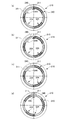
- FIG. 7 is a diagram showing a procedure for attaching the lens barrel to the camera body. It is the front view seen from the to-be-photographed object side in parallel with the optical axis. Before the body outer shell coupling portion 216 and the lens outer shell coupling portion 316 start to engage, the body inner shell coupling portion 217 and the lens inner shell coupling portion 317 start to engage with each other.
- the lens inner shell coupling portion 317 becomes the body inner shell coupling portion 217 as shown in FIG. 7B. Start to hang on.
- the lens outer shell coupling portion 316 is not yet engaged with the body outer shell coupling portion 216.
- the lens outer shell coupling portion 316 is obtained. Begins to hang on the body outer shell coupling portion 216.
- the lens inner shell coupling portion 317 is obtained. Is connected to the body inner shell coupling portion 217. At this time, the lens outer shell coupling portion 316 is not over the body outer shell coupling portion 216. Therefore, when the lens outer shell 301 is further rotated, the lens outer shell coupling portion 316 is engaged with the body outer shell coupling portion 216 and coupled. The lens outer shell coupling portion 316 and the body outer shell coupling portion 216 may be coupled to the lens outer shell coupling portion 216 and the body outer shell coupling portion 216 almost simultaneously with the coupling.
- the timing at which the lens inner shell coupling portion 317 and the body inner shell coupling portion 217 start to engage is earlier than the timing at which the lens outer shell coupling portion 316 and the body outer shell coupling portion 216 begin to engage.
- the rotation amount (rotation angle) of the lens inner shell 302 is insufficient, and the coupling between the body inner shell mount 224 and the lens inner shell mount 326 is insufficient. To prevent becoming.
- the engagement angle of the lens inner shell coupling portion 317 with respect to the body inner shell coupling portion 217 may be made smaller than the engagement angle of the lens outer shell coupling portion 316 with respect to the body outer shell coupling portion 216. Even in this case, the same purpose can be achieved.
- an actuator is provided, and when the lens outer shell 301 of the lens barrel 3 is coupled to the body outer shell 201 of the camera body 2, the lens inner shell 302 of the lens barrel 3 is attached to the camera body 2 as a trigger. It can also be configured to be coupled to the body inner shell 202. Moreover, you may make it perform the same operation
- the mechanisms 1-1 to 1-3 described above may be configured independently, or may be combined as appropriate.
- the camera system 1 is provided with a mechanism for preventing loosening of the connecting portion (a holding mechanism for the connecting portion).
- a mechanism for preventing loosening of the connecting portion a holding mechanism for the connecting portion.
- the camera system 1 includes an inner shell coupling holding mechanism that holds (fixes, locks) the coupling between the lens inner shell coupling portion 317 and the body inner shell coupling portion 217. Further, an outer shell coupling holding mechanism that holds (fixes, locks) the coupling between the lens outer shell coupling portion 316 and the body outer shell coupling portion 216 is provided. Therefore, it is possible to prevent the body inner shell 202 and the lens inner shell 302 from being displaced in the rotational direction around the optical axis during the use of the camera system 1, and the coupling (engagement) from being released.
- the outer shell coupling holding mechanism and the inner shell coupling holding mechanism may be of any type, and for example, mechanical, electrical, and magnetic mechanisms can be used.
- This holding mechanism may include only the outer shell coupling holding mechanism. Because the movable range of the inner shell with respect to the outer shell is regulated to some extent, if the outer shell side is firmly coupled (engaged), there is a low possibility that the inner shell side coupling (engaged) will be disengaged. . That is, if the outer shell coupling holding mechanism is provided, the inner shell side coupling (engagement) can be held. By providing the inner shell coupling holding mechanism, it is possible to suppress a shift in the rotation direction around the optical axis on the inner shell side.
- the camera system 1 includes a release mechanism for releasing the connection between the lens outer shell 301 and the body outer shell 201 by the outer shell coupling holding mechanism.
- a release mechanism for releasing the connection between the lens outer shell 301 and the body outer shell 201 by the outer shell coupling holding mechanism.
- the release mechanism By operating the release mechanism, the lock by the outer shell coupling holding mechanism is released.
- the lock by the inner shell coupling holding mechanism is also released. Therefore, the camera system 1 releases the lock by the outer shell coupling holding mechanism by the release mechanism and also releases the lock by the inner shell coupling holding mechanism. Thereby, attachment / detachment of the lens barrel 3 can be easily performed.
- FIG. 8 is a diagram illustrating an example of a mechanism (coupling portion holding mechanism) that prevents loosening of the coupling portion (for example, a shift in the rotational direction around the optical axis).
- the vertical direction in FIG. 8 is shown as a direction along the optical axis of the lens barrel 3.
- the coupling between the body outer shell coupling portion 216 and the lens outer shell coupling portion 316 is locked by the outer shell mount coupling pin 231, and the lens outer shell 301. Is fixed to the body outer shell 201.
- the outer shell mount coupling pin 231 is biased downward in the figure by a spring 234.
- the inner shell mount coupling pin 232 locks the coupling between the body inner shell coupling portion 217 and the lens inner shell coupling portion 317 and fixes the lens inner shell 302 to the body inner shell 202.
- the inner shell mount coupling pin 232 is biased downward in the figure by a spring 234.
- an interlocking lever 233 is provided so as to be movable up and down so as to straddle the outer shell mount coupling pin 231 and the inner shell mount coupling pin 232.
- the interlocking lever 233 is provided to be movable in a direction along the optical axis of the lens barrel 3 (vertical direction in FIG. 8).
- the outer shell mount coupling pin 231 and the interlocking lever 233 may be configured to be fitted so as to be movable integrally.
- the inner shell mount coupling pin 232 and the interlocking lever 233 have a sufficient movable range in the radial direction of the inner shell mount coupling pin 232 so that the body inner shell 202 can swing relative to the body outer shell 201. Is provided and engaged. Note that the interference between the inner shell mount coupling pin 232 and the interlocking lever 233 in the vertical direction in FIG. 8 due to the swing of the body inner shell 202 can be absorbed by the expansion and contraction of the spring 235.
- the user manually operates the interlocking lever 233. That is, when the interlocking lever 233 is moved upward in FIG. 8, as shown in FIG. 8B, the outer shell mount coupling pin 231 is pushed up by the interlocking lever 233, and the body outer shell coupling portion 216 and the lens outer shell. The outer shell coupling lock that has locked the coupling with the coupling portion 316 is released. At the same time, the inner shell mount coupling pin 232 is also pushed up by the interlocking lever 233, and the inner shell coupling lock that has locked the coupling between the body inner shell coupling portion 217 and the lens inner shell coupling portion 317 is released.
- the release mechanism only by operating the release mechanism, not only the outer shell coupling lock but also the inner shell coupling lock can be released, and the lens barrel 3 can be easily attached and detached. Further, when the lens barrel 3 is attached to the camera body 2, the outer shell coupling lock and the inner shell coupling lock are automatically performed only by rotating the lens barrel 3 to a predetermined position. From the above, the practicality and convenience of the camera system 1 can be improved.
- the present invention is not limited to the outer shell coupling holding mechanism and the inner shell coupling holding mechanism as described above.
- the inner shell coupling holding mechanism may be electrically locked by using an actuator or the like.
- control is performed to release the inner shell coupling lock using the actuator in conjunction with the release. It is good to do.
- the camera system 1 of the present embodiment includes a detection unit that detects (detects) whether or not the inner shells are correctly coupled to each other.
- a detection unit that detects the engagement state between the inner shells is provided.
- the body inner shell 202 is provided with a coupling detection unit 240.
- the lens inner shell 302 is provided with a coupling detection unit 340.
- the coupling detection unit 240 and the coupling detection unit 340 can detect whether the inner shells are correctly coupled to each other. Such a detection unit can communicate or energize. In a state where the body inner shell 202 and the lens inner shell 302 are not properly coupled (for example, FIGS. 7A, 7B, and 7C), the coupling detection unit 240 and the coupling detection unit 340 are not in contact with each other. . On the other hand, when the body inner shell 202 and the lens inner shell 302 are correctly coupled (for example, FIG. 7D), the coupling detection unit 240 and the coupling detection unit 340 are in contact with each other. The coupling detectors can be energized or communicated by contacting each other.
- the coupling detection unit 240 and the coupling detection unit 340 come into contact with each other to detect energization or communication, it can be determined that the lens inner shell 302 and the body inner shell 202 are accurately coupled. If the coupling detection unit 240 and the coupling detection unit 340 are not in contact with each other and no energization or communication is detected, it can be determined that the lens inner shell 302 and the body inner shell 202 are not accurately coupled. Such a determination may be made by the lens control unit 314 or the body control unit 215. By providing the coupling detection unit 240 and the coupling detection unit 340, it is possible to determine the coupling state between the body inner shell 202 and the lens inner shell 302 that cannot be determined from the appearance.
- FIG. 9 is a flowchart illustrating the operation of the body control unit 215 regarding detection of a combined state using the combined detection unit 240 and the combined detection unit 340.
- the lens control unit 314 may perform the operation shown in FIG.
- the body control unit 215 determines whether or not the energization (or communication) of the coupling detection unit 240 and the coupling detection unit 340 is correctly performed, that is, the body It is determined whether or not the inner shell 202 and the lens inner shell 302 are correctly coupled (engaged). If it is determined in S310 that energization or communication is being performed (the lens inner shell 302 and the body inner shell 202 are coupled), the process proceeds to S320. If it is determined that energization or communication is not performed (the lens inner shell 302 and the body inner shell 202 are not coupled), the process proceeds to S340.
- the body control unit 215 continues the operation of the camera system 1. Then, the process proceeds to S330. In S330, the body control unit 215 determines whether or not the power is turned off. If the power is not turned off, the process returns to S310, and if the power is turned off, the operation is terminated.
- the body control unit 215 determines whether or not the mounted lens barrel is a lens barrel having an inner shell. For example, the body control unit 215 receives information about the lens barrel 3 from the lens barrel 3 via the contact 311 provided in the lens outer shell 301 and the contact 211 provided in the body outer shell 201. The information regarding the lens barrel 3 includes information indicating whether or not the lens barrel has an inner shell. If the information related to the lens barrel 3 includes information indicating that the lens barrel is provided with an inner shell (or information indicating that the lens barrel is not provided with an inner shell). The body control unit 215 determines that the attached lens barrel has an inner shell, and proceeds to S350.
- the body control unit 215 determines that the attached lens barrel has an inner shell, and proceeds to S320.
- a lens barrel that does not include the lens inner shell 302 (for example, a lens barrel used in a conventional camera system) is attached to the camera body 2, the lens barrel is used as a camera. Even if it is accurately coupled to the body 2, since the coupling detection unit 340 is not provided in the lens barrel, the coupling detection unit 240 and the coupling detection unit 340 are not energized or communicated. Even when such a lens barrel that does not include the lens inner shell 302 is attached, it is more convenient to use a form that allows photographing.
- the lens barrel 3 having the lens inner shell 302 is attached to the camera body 2
- the lens barrel 3 is moved into the lens via the contact 211 and the contact 311 of the body outer shell 201 and the lens outer shell 301.
- Information indicating that the shell 302 is provided is transmitted from the lens barrel 3 to the camera body 2.
- the camera body 2 can identify whether or not the attached lens barrel has the lens inner shell 302. Therefore, not only the lens barrel 3 including the lens inner shell 302 but also the lens barrel not including the lens inner shell 302 may be attached to the camera body 2. It is possible to properly notify the user whether the inner shell 302 is accurately coupled to the body inner shell 202 of the camera body 2, and a lens barrel that does not include the lens inner shell 302 is attached to the camera body 2. Even if it is mounted, it is possible to take a picture.
- the body control unit 215 notifies the user by sound, display, light, or the like that the body inner shell 202 and the lens inner shell 302 are not properly coupled. In addition to the notification or instead of the notification, the operation of the camera system 1 may be temporarily suspended.
- the lens inner shell 302 of the lens barrel 3 when it is detected that the lens inner shell 302 of the lens barrel 3 is coupled to the body inner shell 202 of the camera body 2, it may be notified to the user.
- the coupling detection unit (240, 340) is used as a non-coupling detection unit for detecting that the coupling between the body inner shell 202 and the lens inner shell 302 is released, that is, a non-coupling state. You can also In this case, for example, when it is detected that the coupling between the body inner shell 202 and the lens inner shell 302 is released, the fact can be notified to the user by sound, display, light, or the like.
- the camera system 1 can remove the camera body 2 and the lens barrel 3 even when the lens inner shell 302 is firmly attached to the body inner shell 202 for some reason and is difficult to remove.
- a forcible release mechanism is further provided.
- the case where the lens inner shell 302 is firmly attached to the body inner shell 202 means that, for example, the lens inner shell coupling portion 317 is attached to the body inner shell coupling portion 217 in an abnormal state such as deformation. It may be difficult to remove.
- the body inner shell 202 or the lens inner shell 302 is inclined with respect to the body outer shell 201 or the lens outer shell 301.
- the lens barrel 3 is difficult to be removed due to being attached.
- no countermeasure for example, a forced release mechanism in the present embodiment
- the lens inner shell 302 and the body inner shell 202 are coupled even if the lens outer shell 301 is rotated. May not be released. In that case, the lens barrel 3 cannot be removed from the camera body 2.
- FIG. 10 is a diagram showing an outline of the coupling release mechanism.
- the coupling release mechanism includes an operation pin 303 that can be attached to the elongated hole 301a of the lens outer shell 301 so as to be movable up and down (movable in the radial direction of the lens outer shell 301) as necessary, and a lens.
- the long hole 301 a is formed so as to extend along the circumferential direction (rotation direction) of the lens outer shell 301.
- the operation pin 303 is attached and the lens inner shell 302 is attached.
- the lens inner shell 302 can be forcibly rotated by moving the operation pin 303 in the circumferential direction of the lens outer shell 301 in this state. Therefore, the reliability of the camera system 1 is improved, and it becomes easy to deal with in an emergency.
- operation pin 303 has been described as an example prepared as a separate component from the lens barrel 3, it may be an accessory attached integrally to the lens barrel 3. Further, a lid that hides the presence of the long hole 301a may be provided.
- FIG. 11 is a diagram showing a modified form of the inner shell side mount configuration. This modified embodiment employs a pin engagement method in place of the bayonet method described above.
- the body inner shell mount 224 has an annular mount body 224f as shown in FIG.
- Two locking holes 224d are formed on the circumference of the mount body 224f at intervals of 180 °.
- two arc-shaped magnets 224e are embedded in the mount body 224f at intervals of 180 ° so as to be positioned between the two locking holes 224d.
- the lens inner shell mount 326 has an annular mount body 326f.
- the mount body 326f two concave portions 326b are formed on the circumference thereof at intervals of 180 ° corresponding to the two locking holes 224d of the body inner shell mount 224.
- a cylindrical pin (so-called bullet-shaped) engagement pin 326d having a hemispherical tip is attached to each recess 326b via a coil spring 326c so as to be able to move forward and backward.
- the lens inner shell mount 326 is attached to the body inner shell mount 224 by engaging the two engaging pins 326 d with the two recesses 326 b. Then, the lens inner shell mount 326 can be fixed to the body inner shell mount 224 by the magnetic force of the magnet 224e. As a result, the lens inner shell 302 of the lens barrel 3 and the body inner shell 202 of the camera body 2 can be easily combined with high accuracy.
- Such a pin engagement method is mechanical and not electrical like the bayonet method, so the battery 212 is cut carelessly and the lens inner shell mount 326 is removed from the body inner shell mount 224. There is an advantage that the inconvenience of dropping off can be avoided in advance.
- this pin engagement method is not limited to the connection between the body inner shell mount 224 and the lens inner shell mount 326 but may be adopted for the connection between the body outer shell mount 210 and the lens outer shell mount 310.
- the contact 211 for communication or energization is provided at the subject side end of the body outer shell 201. Further, a contact 311 for communication or energization is provided at the body side end of the lens outer shell 301. Therefore, the transmission and reception of electric signals and electric power between the camera body 2 and the lens barrel 3 can be performed entirely on the outer shell side. Accordingly, even when a conventional camera system that does not include the lens inner shell 302 or the body inner shell 202 is coupled to the lens outer shell 301 or the body outer shell 201, communication or energization with the conventional camera system is possible. It is. Therefore, the conventional camera system can be used by being attached to and detached from the camera system 1.
- the yaw driving unit 312 or the pitch driving unit 322 is provided in the lens outer shell 301, the camera body 2 and the lens barrel 3 are arranged on the outer shell side where the yaw driving unit 312 or the pitch driving unit 322 is arranged.
- the number and size of FPCs and the like in the interior can be minimized if the electrical signals and power are exchanged between them. If the FPC is arranged between the inner shell and the outer shell, it is a load for the oscillation of the inner shell. Therefore, reducing the FPC has a great effect in the camera system 1. .
- the lens barrel 3 of the camera system 1 is provided with the contact 311 on the lens outer shell 301, this lens barrel can be applied to a camera body (not shown) that does not include the body inner shell 202. 3 can be used.
- the lens inner shell 302 is locked to the lens outer shell 301 by the lens lock mechanism described above, thereby preventing the occurrence of a situation where the optical axis of the lens unit L is blurred. Can do.
- the lens blur correction can be executed even when the lens barrel 3 is mounted on a camera body that does not include the body inner shell 202. it can. Further, if image pickup device shake correction is performed by driving the image pickup device in any one of pitch, yaw, roll, and shift, shake correction can be executed. Further, when the lens barrel 3 of the camera system 1 does not have such a function, it is possible to drive the entire lens inner shell 302 of the lens barrel 3 to perform blur correction.
- the contact 311 and the contact 211 demonstrated the structure provided in the outer shell side, you may be provided in the inner shell side. It may be provided on the outer shell side and the inner shell side. Since the zoom actuator for driving the lens group L is provided in the lens inner shell 302, it is preferable to use the contacts 211 and 311 provided on the inner shell side for information on driving the zoom actuator. In this way, information necessary for the control may be transmitted and received at the contact point on the side (inner shell side or outer shell side) where the object to be controlled is provided.
- the lens barrel 3 of the camera system 1 is configured so that the lens inner shell 302 does not protrude rearward (camera body 2 side) from the lens outer shell 301 along the optical axis direction. For this reason, there is a possibility that the lens inner shell 302 may interfere with camera body components (mirror, shutter, etc.) not only when attached to a camera body that does not include the body inner shell 202 but also during shake correction. Absent. Further, when the lens barrel 3 is attached to a camera body that does not include the body inner shell 202, the entire lens inner shell 302 is moved forward (subject side) by an actuator (not shown), so that It is also possible to prevent the shell 302 from interfering with parts of the camera body.
- camera body components mirror, shutter, etc.
- the camera body 2 of the camera system 1 is provided with a contact 211 on the body outer shell 201. Therefore, a lens barrel (not shown) that does not include the lens inner shell 302 can be used by being mounted on the camera body 2.
- a lens barrel (not shown) that does not include the lens inner shell 302 can be used by being mounted on the camera body 2.
- the body inner shell 202 by causing the body inner shell 202 to be locked to the body outer shell 201 by the body lock mechanism described above, it is possible to prevent the occurrence of a situation where the position of the image sensor 220 is blurred. .
- the camera body 2 of the camera system 1 is configured such that the body inner shell 202 does not protrude forward (subject side) from the body outer shell 201 along the optical axis direction. Therefore, even when a lens barrel that does not include the lens inner shell 302 is attached, the body inner shell 202 is a part of the lens barrel (the rearmost of the lens group L (camera There is no possibility of interfering with a lens or the like located on the body 2 side). Further, when a lens barrel that does not include the lens inner shell 302 is attached to the camera body 2, the body inner shell 202 is moved to the lens by moving the entire body inner shell 202 backward by an actuator (not shown). It is also possible to prevent interference with the lens barrel components.
- FIG. 12A is a system configuration diagram of a camera system 1 including a lens barrel 3 and a camera body 2 according to the second embodiment.
- FIG. 12B is a diagram illustrating a simplified system configuration of the camera system 1 including the lens barrel 3 and the camera body 2 according to the second embodiment. Since the same camera system 1 is shown in FIGS. 12A and 12B as in the relationship of FIGS. 1A and 1B, these drawings are not included in one figure, for example. Shall be supplemented on the other hand, and they complement each other.
- FIGS. 12A is a system configuration diagram of a camera system 1 including a lens barrel 3 and a camera body 2 according to the second embodiment.
- a contact 211 on the camera body 2 side is provided not on the body outer shell 201 but on the body inner shell 202.
- the body control unit 215 is provided not on the body outer shell 201 of the camera body 2 but on the body inner shell 202.
- a contact 311 on the lens barrel 3 side is provided not on the lens outer shell 301 but on the lens inner shell 302.
- the lens control unit 314 is provided not in the lens outer shell 301 of the lens barrel 3 but in the lens inner shell 302. Since other configurations are basically the same as those of the first embodiment described above, the same members are denoted by the same reference numerals and description thereof is omitted.
- the same effects as the first embodiment described above are achieved.
- electrical components for example, for zooming
- Electric power can be supplied from the battery 212 to the actuator, the shift direction image stabilization system 330, etc. without going through the FPC, and the FPC can be reduced by that amount.
- electrical signals can be transmitted to and received from the electrical components installed in the lens inner shell 302 without going through the FPC, and the FPC can be reduced accordingly.
- the contact points 211 and the contact points 311 are provided in the number corresponding to the communication amount, it is possible to appropriately execute transmission / reception of electric signals with the electric parts installed in the lens inner shell 302.
- the lens barrel 3 includes the pitch driving unit 322 and the yaw driving unit 312 has been described.
- the camera body 2 may include the pitch driving unit 322 or the yaw driving unit 312. Both drive units may be provided in the camera body 2, one drive unit may be provided in the camera body 2, and the other drive unit may be provided in the lens barrel 3.
- blur correction is performed by driving the lens inner shell 302 and the body inner shell 202 in the pitch direction or the yaw direction.
- the present invention is not limited to this, and the lens inner shell 302 and the body inner shell 202 may be driven in the shift direction to perform blur correction.
- a drive unit that can be driven in the shift direction is provided to drive the lens inner shell 302 or the housing 320 in the shift direction.
- the configuration may include at least one of integrated drive blur correction, lens blur correction, and image sensor blur correction, or may include a plurality of blur corrections.
- the example in which the shake detection unit 325 is provided has been described.
- a plurality of shake detection units may be provided. Any one of the plurality of blur detection units may be provided in the lens outer shell 301, the body inner shell 202, or the body outer shell 201.
Abstract
A camera system and a lens barrel are provided in an exchangeable-lens camera comprising a shake correction mechanism that integrally drives the lens barrel and an imaging unit, it being possible for lenses to be smoothly exchange, and greater utility and convenience to be obtained. A lens barrel, to and from which a camera body can be attached or detached, wherein the lens barrel comprises: a first barrel having a first engagement part that engages with a first part of the camera body; a second barrel disposed inside the first barrel, the second barrel having a second engagement part that engages with a second part of the camera body, and an optical system; and a retention mechanism that retains the engagement state between the first engagement part and the first part, and the engagement state between the second engagement part and the second part.
Description
本発明は、レンズ鏡筒、カメラボディ、カメラシステムに関するものである。
The present invention relates to a lens barrel, a camera body, and a camera system.
動画撮影が可能な撮像装置において、広い範囲のブレ補正角を補正するために、従来、撮像部と一体のレンズ鏡筒を撮像装置の外枠に対して揺動可能とし、光軸に直交する支持軸を有する2つの駆動部を備えるブレ補正機構が存在する(特許文献1参照)。
2. Description of the Related Art Conventionally, in order to correct a wide range of blur correction angles in an imaging device capable of shooting a moving image, a lens barrel integrated with an imaging unit can be swung with respect to the outer frame of the imaging device, and is orthogonal to the optical axis. There is a blur correction mechanism including two drive units having a support shaft (see Patent Document 1).
一方、レンズ交換式カメラにおいては、レンズを交換する際に、カメラボディに対してレンズ鏡筒を着脱できるようにする必要がある。
On the other hand, in the interchangeable lens camera, it is necessary to be able to attach and detach the lens barrel with respect to the camera body when the lens is replaced.
本発明のレンズ鏡筒は、カメラボディを着脱可能なレンズ鏡筒であって、前記カメラボディの第1部と係合する第1係合部を有する第1筒と、前記第1筒の内側に配置され、前記カメラボディの第2部と係合する第2係合部と光学系とを有する第2筒と、前記第1係合部と前記第1部との係合状態、及び、前記第2係合部と前記第2部との係合状態を保持する保持機構と、を備える構成とした。
また、本発明のカメラボディは、レンズ鏡筒を着脱可能なカメラボディであって、前記レンズ鏡筒の第1筒と係合する第1係合部を有する第1筐体と、前記第1筐体の内側に配置され、前記レンズ鏡筒の第2筒と係合する第2係合部と光学系とを有する第2筐体と、前記第1係合部と前記第1筒との係合状態、及び、前記第2係合部と前記第2筒との係合状態を保持する保持機構と、を備える構成とした。
また、本発明のカメラシステムは、カメラボディとレンズ鏡筒とが着脱可能なカメラシステムであって、前記カメラボディは、第1筐体と、撮像素子を有する第2筐体と、を備え、前記レンズ鏡筒は、前記第1筐体と係合する第1筒と、光学系を有し、前記第2筐体と係合する第2筒と、を備え、前記カメラボディ又は前記レンズ鏡筒は、前記第1筐体と前記第1筒との係合状態、及び、前記第2筐体と前記第2筒との係合状態を保持する保持機構を有する構成とした。 The lens barrel of the present invention is a lens barrel to which a camera body can be attached and detached. A second cylinder having a second engaging portion and an optical system that are engaged with the second portion of the camera body, an engagement state of the first engaging portion and the first portion, and And a holding mechanism for holding the engaged state between the second engaging portion and the second portion.
The camera body of the present invention is a camera body to which a lens barrel can be attached and detached, and includes a first housing having a first engagement portion that engages with the first barrel of the lens barrel, and the first casing. A second housing having a second engaging portion and an optical system which are disposed inside the housing and engage with the second tube of the lens barrel; and the first engaging portion and the first tube An engagement state and a holding mechanism for holding the engagement state between the second engagement portion and the second cylinder are provided.
The camera system of the present invention is a camera system in which a camera body and a lens barrel are detachable, and the camera body includes a first housing and a second housing having an image sensor, The lens barrel includes: a first cylinder that engages with the first casing; and a second cylinder that has an optical system and engages with the second casing, and the camera body or the lens mirror. The cylinder is configured to have a holding mechanism that holds the engagement state between the first casing and the first cylinder and the engagement state between the second casing and the second cylinder.
以下、図面等を参照して説明する。
以下の説明において、理解を容易にするために、必要に応じてピッチ軸P、ヨー軸Y、ロール軸Rという文言を用いる。実施形態において、ピッチ軸Pは、レンズ鏡筒3をカメラボディ2に装着した際に、撮影者が光軸を水平として横長の画像を撮影する場合のカメラボディ2の位置(以下、正位置という)において撮影者から見て左右方向に延在する軸である。ヨー軸Yは、正位置において上下方向に延在する軸である。ロール軸Rは、正位置において光軸方向に延在する軸である。よって、ピッチ軸P、ヨー軸Y、ロール軸Rは、互いに直交している。なお、「直交」とは厳密に90度だけでなく、製造誤差や組立誤差によって90度から、若干ずれた範囲も含まれる。
また、ピッチ軸Pを中心とした回転をピッチング、ヨー軸Yを中心とした回転をヨーイング、ロール軸Rを中心とした回転をローリングとする。さらに、ピッチングの方向をピッチ方向、ヨーイングの方向をヨー方向、ローリングの方向をロール方向とする。
また、ピッチ軸Pに沿った方向又はヨー軸Yに沿った方向をシフト方向とする。 Hereinafter, description will be given with reference to the drawings.
In the following description, in order to facilitate understanding, terms such as a pitch axis P, a yaw axis Y, and a roll axis R are used as necessary. In the embodiment, the pitch axis P is a position of the camera body 2 (hereinafter referred to as a normal position) when the photographer takes a horizontally long image with the optical axis horizontal when thelens barrel 3 is attached to the camera body 2. ) In the horizontal direction when viewed from the photographer. The yaw axis Y is an axis extending in the vertical direction at the normal position. The roll axis R is an axis extending in the optical axis direction at the normal position. Therefore, the pitch axis P, the yaw axis Y, and the roll axis R are orthogonal to each other. Note that “orthogonal” includes not only strictly 90 degrees but also a range slightly deviated from 90 degrees due to manufacturing errors and assembly errors.
Further, the rotation around the pitch axis P is pitched, the rotation around the yaw axis Y is yawing, and the rotation around the roll axis R is rolling. Further, the pitching direction is the pitch direction, the yawing direction is the yaw direction, and the rolling direction is the roll direction.
A direction along the pitch axis P or a direction along the yaw axis Y is defined as a shift direction.
以下の説明において、理解を容易にするために、必要に応じてピッチ軸P、ヨー軸Y、ロール軸Rという文言を用いる。実施形態において、ピッチ軸Pは、レンズ鏡筒3をカメラボディ2に装着した際に、撮影者が光軸を水平として横長の画像を撮影する場合のカメラボディ2の位置(以下、正位置という)において撮影者から見て左右方向に延在する軸である。ヨー軸Yは、正位置において上下方向に延在する軸である。ロール軸Rは、正位置において光軸方向に延在する軸である。よって、ピッチ軸P、ヨー軸Y、ロール軸Rは、互いに直交している。なお、「直交」とは厳密に90度だけでなく、製造誤差や組立誤差によって90度から、若干ずれた範囲も含まれる。
また、ピッチ軸Pを中心とした回転をピッチング、ヨー軸Yを中心とした回転をヨーイング、ロール軸Rを中心とした回転をローリングとする。さらに、ピッチングの方向をピッチ方向、ヨーイングの方向をヨー方向、ローリングの方向をロール方向とする。
また、ピッチ軸Pに沿った方向又はヨー軸Yに沿った方向をシフト方向とする。 Hereinafter, description will be given with reference to the drawings.
In the following description, in order to facilitate understanding, terms such as a pitch axis P, a yaw axis Y, and a roll axis R are used as necessary. In the embodiment, the pitch axis P is a position of the camera body 2 (hereinafter referred to as a normal position) when the photographer takes a horizontally long image with the optical axis horizontal when the
Further, the rotation around the pitch axis P is pitched, the rotation around the yaw axis Y is yawing, and the rotation around the roll axis R is rolling. Further, the pitching direction is the pitch direction, the yawing direction is the yaw direction, and the rolling direction is the roll direction.
A direction along the pitch axis P or a direction along the yaw axis Y is defined as a shift direction.
(第1実施形態)
図1Aは、第1実施形態のレンズ鏡筒3と、カメラボディ2とを備えるカメラシステム1のシステム構成図である。図1Bは、第1実施形態のレンズ鏡筒3と、カメラボディ2とを備えるカメラシステム1のシステム構成を簡素化して示した図である。なお、図1Aと図1Bとは、同じカメラシステム1を示しているので、これらの図は、例えば、一方の図に含まれていない構成については、他方で補うものとし、これらは相互に補完するものである。
カメラシステム1は、ズーム可能なシステムであってもよいし、ズームのできないシステムであってもよい。 (First embodiment)
FIG. 1A is a system configuration diagram of a camera system 1 including alens barrel 3 and a camera body 2 according to the first embodiment. FIG. 1B is a diagram illustrating a simplified system configuration of a camera system 1 including the lens barrel 3 and the camera body 2 according to the first embodiment. 1A and 1B show the same camera system 1, these drawings are supplemented on the other side, for example, for configurations not included in one figure, and they complement each other. To do.
The camera system 1 may be a zoomable system or a system that cannot zoom.
図1Aは、第1実施形態のレンズ鏡筒3と、カメラボディ2とを備えるカメラシステム1のシステム構成図である。図1Bは、第1実施形態のレンズ鏡筒3と、カメラボディ2とを備えるカメラシステム1のシステム構成を簡素化して示した図である。なお、図1Aと図1Bとは、同じカメラシステム1を示しているので、これらの図は、例えば、一方の図に含まれていない構成については、他方で補うものとし、これらは相互に補完するものである。
カメラシステム1は、ズーム可能なシステムであってもよいし、ズームのできないシステムであってもよい。 (First embodiment)
FIG. 1A is a system configuration diagram of a camera system 1 including a
The camera system 1 may be a zoomable system or a system that cannot zoom.
(レンズ鏡筒3)
本実施形態のレンズ鏡筒3は、カメラボディ2に対して着脱可能である。また、レンズ鏡筒3は、縮筒状態(非撮影状態,収納状態,沈胴状態)と、伸長状態(撮影状態)との間で伸縮可能である。
レンズ鏡筒3は、図1A,1Bのシステム構成図に示すように、結像光学系であるレンズ群Lを内部に保持するレンズ内殻302、レンズ内殻302の外周に配置された筐体320、及び筐体320の外周に配置されたレンズ外殻301(例えば、固定筒)等を備える。レンズ内殻302と筐体320とを合わせてレンズ内殻としてもよい。 (Lens barrel 3)
Thelens barrel 3 of this embodiment is detachable from the camera body 2. The lens barrel 3 can be expanded and contracted between a contracted state (non-photographed state, a stored state, a retracted state) and an extended state (photographed state).
As shown in the system configuration diagram of FIGS. 1A and 1B, thelens barrel 3 includes a lens inner shell 302 that holds a lens group L that is an imaging optical system inside, and a housing that is disposed on the outer periphery of the lens inner shell 302. 320 and a lens outer shell 301 (for example, a fixed cylinder) disposed on the outer periphery of the housing 320. The lens inner shell 302 and the housing 320 may be combined to form a lens inner shell.
本実施形態のレンズ鏡筒3は、カメラボディ2に対して着脱可能である。また、レンズ鏡筒3は、縮筒状態(非撮影状態,収納状態,沈胴状態)と、伸長状態(撮影状態)との間で伸縮可能である。
レンズ鏡筒3は、図1A,1Bのシステム構成図に示すように、結像光学系であるレンズ群Lを内部に保持するレンズ内殻302、レンズ内殻302の外周に配置された筐体320、及び筐体320の外周に配置されたレンズ外殻301(例えば、固定筒)等を備える。レンズ内殻302と筐体320とを合わせてレンズ内殻としてもよい。 (Lens barrel 3)
The
As shown in the system configuration diagram of FIGS. 1A and 1B, the
本実施形態のレンズ鏡筒3において、レンズ内殻302は、筐体320に対してピッチ軸Pを中心としてピッチ方向に回転可能である。また、筐体320は、レンズ外殻301に対してヨー軸Yを中心としてヨー方向に回転可能である。
In the lens barrel 3 of the present embodiment, the lens inner shell 302 can rotate in the pitch direction about the pitch axis P with respect to the housing 320. The housing 320 is rotatable in the yaw direction about the yaw axis Y with respect to the lens outer shell 301.
レンズ鏡筒3の全体としての外形が円筒形状の場合、レンズ内殻、レンズ外殻、筐体も円筒形状であることが考えられる。しかし、他部品配置等のために内周面又は外周面に平坦部を設けてもよい。また、レンズ内殻、レンズ外殻、筐体の形状は、適宜、平坦部・切欠き・厚みの変化する部分等を形成して変形してもよい。円筒形状でなく、四角柱のような形状であってもよい。
When the outer shape of the lens barrel 3 as a whole is cylindrical, the lens inner shell, the lens outer shell, and the housing may be cylindrical. However, a flat portion may be provided on the inner peripheral surface or the outer peripheral surface for arranging other components. In addition, the shape of the lens inner shell, lens outer shell, and housing may be modified by forming a flat portion, a notch, a portion whose thickness changes, or the like as appropriate. Instead of a cylindrical shape, a shape such as a quadrangular prism may be used.
(レンズ内殻302)
図1A,1Bに示すようにレンズ鏡筒3のレンズ内殻302は、レンズ群Lと、シフト方向防振システム330と、ブレ検出部325と、レンズ内殻マウント326と、を備える。
また、レンズ内殻302は、レンズ内殻302を筐体320に対して、ピッチ方向に駆動するピッチ駆動部322の一部を備える。 (Lens inner shell 302)
As shown in FIGS. 1A and 1B, the lensinner shell 302 of the lens barrel 3 includes a lens group L, a shift direction image stabilization system 330, a blur detection unit 325, and a lens inner shell mount 326.
In addition, the lensinner shell 302 includes a part of a pitch driving unit 322 that drives the lens inner shell 302 in the pitch direction with respect to the housing 320.
図1A,1Bに示すようにレンズ鏡筒3のレンズ内殻302は、レンズ群Lと、シフト方向防振システム330と、ブレ検出部325と、レンズ内殻マウント326と、を備える。
また、レンズ内殻302は、レンズ内殻302を筐体320に対して、ピッチ方向に駆動するピッチ駆動部322の一部を備える。 (Lens inner shell 302)
As shown in FIGS. 1A and 1B, the lens
In addition, the lens
レンズ群Lは、被写体像をカメラボディ2に配置された撮像素子220に結像する結像光学系である。また、レンズ群Lは防振光学系LBを含む。防振光学系LBはシフト方向に移動し、手振れ等による像ブレを補正することができる。
The lens group L is an imaging optical system that forms a subject image on the image sensor 220 disposed in the camera body 2. The lens group L includes an anti-vibration optical system LB. The image stabilizing optical system LB moves in the shift direction and can correct image blur due to camera shake or the like.
シフト方向防振システム330は、シフト方向に移動する防振光学系LBを制御するシステムである。防振光学系LBを保持する可動枠、防振光学系LBの位置を検出する防振光学系位置検出部、可動枠をシフト方向に駆動するシフト駆動部332、等を備える。シフト駆動部332は、ボイスコイルモータ(VCM)等があげられる。シフト駆動部332により、防振光学系LBは、撮影者の手ブレ等に起因する被写体像の像ブレを打ち消す方向に駆動され、像ブレが補正される。
The shift direction image stabilization system 330 is a system that controls the image stabilization optical system LB that moves in the shift direction. A movable frame that holds the image stabilization optical system LB, an image stabilization optical system position detection unit that detects the position of the image stabilization optical system LB, a shift drive unit 332 that drives the movable frame in the shift direction, and the like are provided. An example of the shift drive unit 332 is a voice coil motor (VCM). The image stabilization optical system LB is driven by the shift drive unit 332 in a direction that cancels image blur of the subject image caused by camera shake of the photographer, and image blur is corrected.
ブレ検出部325は、レンズ内殻302のピッチ方向、ヨー方向、ロール方向又はシフト方向の振れを検出する。ブレ検出部325は、少なくとも1つの方向の振れを検出すればよい。全ての方向のブレを検出してもよい。
ブレ検出部325は、ジャイロセンサ等があげられる。1つのセンサで構成されてもよいし、複数のセンサで構成されてもよい。 Theshake detection unit 325 detects shake in the pitch direction, yaw direction, roll direction, or shift direction of the lens inner shell 302. The shake detection unit 325 may detect a shake in at least one direction. Blur in all directions may be detected.
Theshake detection unit 325 is a gyro sensor or the like. It may be composed of one sensor or a plurality of sensors.
ブレ検出部325は、ジャイロセンサ等があげられる。1つのセンサで構成されてもよいし、複数のセンサで構成されてもよい。 The
The
レンズ内殻マウント326は、レンズ内殻結合部317を備えた形状であり、後述するボディ内殻マウント224と接触する。また、レンズ内殻マウント326は、結合検知部340を有する。詳細は後述する。
The lens inner shell mount 326 has a shape including a lens inner shell coupling portion 317 and is in contact with a body inner shell mount 224 described later. In addition, the lens inner shell mount 326 includes a coupling detection unit 340. Details will be described later.
(筐体320)
筐体320は、ピッチ駆動部322とピッチ方向回転検出部323とを備える。ピッチ駆動部322は、レンズ内殻302をピッチ方向に駆動する。ピッチ駆動部322が駆動されると、レンズ内殻302はピッチ軸Pを中心としたピッチ方向に回転する。 (Case 320)
Thehousing 320 includes a pitch driving unit 322 and a pitch direction rotation detection unit 323. The pitch driving unit 322 drives the lens inner shell 302 in the pitch direction. When the pitch driving unit 322 is driven, the lens inner shell 302 rotates in the pitch direction about the pitch axis P.
筐体320は、ピッチ駆動部322とピッチ方向回転検出部323とを備える。ピッチ駆動部322は、レンズ内殻302をピッチ方向に駆動する。ピッチ駆動部322が駆動されると、レンズ内殻302はピッチ軸Pを中心としたピッチ方向に回転する。 (Case 320)
The
ピッチ方向回転検出部323は、レンズ内殻302のピッチ方向の回転量を検出する。言い換えると、ピッチ方向回転検出部323は、ピッチ駆動部322の駆動量を検出する。ピッチ方向回転検出部323がレンズ内殻302の回転量(又はピッチ駆動部322の駆動量)を検出することで、レンズ内殻302(又はピッチ駆動部322)が正確に駆動されているかを判断することができる。また、筐体320は、筐体320をレンズ外殻301に対してヨー方向に駆動するヨー駆動部312の一部を備える。
ヨー駆動部312が駆動すると、筐体320が、レンズ外殻301に対してヨー方向に駆動される。それに伴って、レンズ内殻302もヨー方向に駆動される。 The pitch directionrotation detection unit 323 detects the rotation amount of the lens inner shell 302 in the pitch direction. In other words, the pitch direction rotation detection unit 323 detects the drive amount of the pitch drive unit 322. The pitch direction rotation detection unit 323 detects the rotation amount of the lens inner shell 302 (or the driving amount of the pitch driving unit 322), thereby determining whether the lens inner shell 302 (or the pitch driving unit 322) is driven accurately. can do. The housing 320 includes a part of a yaw driving unit 312 that drives the housing 320 in the yaw direction with respect to the lens outer shell 301.
When theyaw driving unit 312 is driven, the housing 320 is driven in the yaw direction with respect to the lens outer shell 301. Along with this, the lens inner shell 302 is also driven in the yaw direction.
ヨー駆動部312が駆動すると、筐体320が、レンズ外殻301に対してヨー方向に駆動される。それに伴って、レンズ内殻302もヨー方向に駆動される。 The pitch direction
When the
(レンズ外殻301)
レンズ外殻301は、図1A,1Bに示すように、ヨー駆動部312と、ヨー方向回転検出部313と、操作部材315、レンズ外殻マウント310と、レンズ制御部314と、を備える。ヨー駆動部312は、筐体320をヨー方向に駆動する。ヨー方向回転検出部313は、筐体320のヨー方向の回転を検出する。言い換えると、ヨー方向回転検出部313は、ヨー駆動部312の駆動量を検出する。ヨー方向回転検出部313が筐体320の回転量(又はヨー駆動部312の駆動量)を検出することで、筐体320(又はピッチ駆動部322)が正確に駆動されているかを判断することができる。操作部材315は、使用者によって操作される部材である。
レンズ外殻マウント310は、通信又は通電用の接点311を備える。また、レンズ外殻マウント310は、レンズ外殻結合部316を備える形状である。
レンズ制御部314は、シフト駆動部332、ピッチ駆動部322、ヨー駆動部312を制御する。また、レンズ制御部314は、後述する操作部材315を使用者が操作した場合、レンズ群Lを光軸方向に移動させ、焦点距離を変更させる。
レンズ外殻301とレンズ内殻302との間は、フレキシブルプリント配線板(以下、FPC)等の配線部により電気的に接続されている。 (Lens outer shell 301)
As shown in FIGS. 1A and 1B, the lensouter shell 301 includes a yaw driving unit 312, a yaw direction rotation detecting unit 313, an operation member 315, a lens outer shell mount 310, and a lens control unit 314. The yaw drive unit 312 drives the housing 320 in the yaw direction. The yaw direction rotation detection unit 313 detects the rotation of the housing 320 in the yaw direction. In other words, the yaw direction rotation detection unit 313 detects the drive amount of the yaw drive unit 312. The yaw direction rotation detection unit 313 detects the rotation amount of the housing 320 (or the driving amount of the yaw driving unit 312) to determine whether the housing 320 (or the pitch driving unit 322) is driven accurately. Can do. The operation member 315 is a member operated by the user.
The lensouter shell mount 310 includes a contact 311 for communication or energization. The lens outer shell mount 310 has a shape including a lens outer shell coupling portion 316.
Thelens control unit 314 controls the shift driving unit 332, the pitch driving unit 322, and the yaw driving unit 312. In addition, when the user operates an operation member 315 described later, the lens control unit 314 moves the lens group L in the optical axis direction and changes the focal length.
The lensouter shell 301 and the lens inner shell 302 are electrically connected by a wiring portion such as a flexible printed wiring board (hereinafter referred to as FPC).
レンズ外殻301は、図1A,1Bに示すように、ヨー駆動部312と、ヨー方向回転検出部313と、操作部材315、レンズ外殻マウント310と、レンズ制御部314と、を備える。ヨー駆動部312は、筐体320をヨー方向に駆動する。ヨー方向回転検出部313は、筐体320のヨー方向の回転を検出する。言い換えると、ヨー方向回転検出部313は、ヨー駆動部312の駆動量を検出する。ヨー方向回転検出部313が筐体320の回転量(又はヨー駆動部312の駆動量)を検出することで、筐体320(又はピッチ駆動部322)が正確に駆動されているかを判断することができる。操作部材315は、使用者によって操作される部材である。
レンズ外殻マウント310は、通信又は通電用の接点311を備える。また、レンズ外殻マウント310は、レンズ外殻結合部316を備える形状である。
レンズ制御部314は、シフト駆動部332、ピッチ駆動部322、ヨー駆動部312を制御する。また、レンズ制御部314は、後述する操作部材315を使用者が操作した場合、レンズ群Lを光軸方向に移動させ、焦点距離を変更させる。
レンズ外殻301とレンズ内殻302との間は、フレキシブルプリント配線板(以下、FPC)等の配線部により電気的に接続されている。 (Lens outer shell 301)
As shown in FIGS. 1A and 1B, the lens
The lens
The
The lens
(カメラボディ2)
次に、カメラボディ2の説明をする。
図1A,1Bのシステム構成図に示すように、カメラボディ2は、ボディ内殻202と、ボディ外殻201(例えば、ボディ固定部)とを備える。 (Camera body 2)
Next, thecamera body 2 will be described.
As shown in the system configuration diagrams of FIGS. 1A and 1B, thecamera body 2 includes a body inner shell 202 and a body outer shell 201 (for example, a body fixing portion).
次に、カメラボディ2の説明をする。
図1A,1Bのシステム構成図に示すように、カメラボディ2は、ボディ内殻202と、ボディ外殻201(例えば、ボディ固定部)とを備える。 (Camera body 2)
Next, the
As shown in the system configuration diagrams of FIGS. 1A and 1B, the
ボディ内殻202は、撮像素子220と、撮像素子駆動部223と、ボディ内殻マウント224とを備える。ボディ外殻201は、ボディ制御部215と、画像処理部218と、ボディ外殻マウント210と、表示部214と、バッテリ212と、操作部材213とを備える。
The body inner shell 202 includes an image sensor 220, an image sensor driver 223, and a body inner shell mount 224. The body outer shell 201 includes a body control unit 215, an image processing unit 218, a body outer shell mount 210, a display unit 214, a battery 212, and an operation member 213.
撮像素子220は、結像光学系(レンズ群L)から入射した光を受光して電気信号に変換する。撮像素子駆動部223は、撮像素子220を駆動してブレ補正を行う。ボディ内殻マウント224は、ボディ内殻結合部217を備える形状であり、レンズ内殻マウント326と接触する。また、結合検知部240を有する。詳細は後述する。
The image sensor 220 receives light incident from the imaging optical system (lens group L) and converts it into an electrical signal. The image sensor driving unit 223 drives the image sensor 220 to perform blur correction. The body inner shell mount 224 has a shape including a body inner shell coupling portion 217 and is in contact with the lens inner shell mount 326. Further, it has a combination detection unit 240. Details will be described later.
ボディ制御部215は、後述するブレ補正の演算や制御を行う。また、操作部材213の入力等に基づいて各種制御を行う。画像処理部218は、撮像素子220から出力された画像データに画像処理を施す。
The body control unit 215 performs shake correction calculation and control, which will be described later. Various controls are performed based on the input of the operation member 213 and the like. The image processing unit 218 performs image processing on the image data output from the image sensor 220.
ボディ外殻マウント210は、通信又は通電用の接点211を備える。また、ボディ外殻マウント210は、ボディ外殻結合部216を備える形状である。表示部214は、撮像素子220が取得した画像データや各種設定に関する情報を表示する。操作部材213は、使用者によって操作される。
また、ボディ外殻201とボディ内殻202との間は、FPC等の配線で電気的に接続されている。 The bodyouter shell mount 210 includes a contact 211 for communication or energization. The body outer shell mount 210 has a shape including a body outer shell coupling portion 216. The display unit 214 displays image data acquired by the image sensor 220 and information related to various settings. The operation member 213 is operated by the user.
The bodyouter shell 201 and the body inner shell 202 are electrically connected by wiring such as FPC.
また、ボディ外殻201とボディ内殻202との間は、FPC等の配線で電気的に接続されている。 The body
The body
以上の構成により、本実施形態のカメラシステム1は、レンズ鏡筒3が交換可能なカメラシステムであって、レンズ内殻302とボディ内殻202とが一体となってブレ補正動作(以下、一体駆動ブレ補正とする。)を行うことができる。
このカメラシステム1において、カメラボディ2のボディ外殻201とレンズ鏡筒3のレンズ外殻301とが結合して一体になる。また、カメラボディ2のボディ内殻202とレンズ鏡筒3のレンズ内殻302とが結合して一体になる。この状態で、ブレ検出部325がピッチ方向又はヨー方向のブレを検出すると、その出力信号に基づいて、レンズ制御部314は、ブレ検出部325が検出したブレを打ち消す方向にヨー駆動部312及びピッチ駆動部322を駆動する。その結果、ブレ補正が実行される。撮影者の手ブレ等に起因する被写体像の像ブレが補正される。また、シフト方向防振システム330を用いるレンズシフトブレ補正を同時に、又は、選択的に行うようにすることもできる。さらに、図示しない駆動部で、撮像素子220をシフト方向、ピッチ方向、ヨー方向、ロール方向のいずれかに駆動して行うブレ補正を同時に又は選択的に行うようにしてもよい。 With the above configuration, the camera system 1 according to the present embodiment is a camera system in which thelens barrel 3 can be replaced, and the lens inner shell 302 and the body inner shell 202 are integrated into a shake correction operation (hereinafter, integrated). Drive blur correction).
In this camera system 1, the bodyouter shell 201 of the camera body 2 and the lens outer shell 301 of the lens barrel 3 are combined and integrated. Further, the body inner shell 202 of the camera body 2 and the lens inner shell 302 of the lens barrel 3 are combined and integrated. In this state, when the shake detection unit 325 detects a shake in the pitch direction or the yaw direction, based on the output signal, the lens control unit 314 causes the yaw drive unit 312 and the direction to cancel the shake detected by the shake detection unit 325 and The pitch drive unit 322 is driven. As a result, blur correction is executed. The image blur of the subject image caused by the camera shake of the photographer is corrected. Further, lens shift blur correction using the shift direction image stabilization system 330 can be performed simultaneously or selectively. Furthermore, the blur correction performed by driving the image sensor 220 in any one of the shift direction, the pitch direction, the yaw direction, and the roll direction by a driving unit (not shown) may be performed simultaneously or selectively.
このカメラシステム1において、カメラボディ2のボディ外殻201とレンズ鏡筒3のレンズ外殻301とが結合して一体になる。また、カメラボディ2のボディ内殻202とレンズ鏡筒3のレンズ内殻302とが結合して一体になる。この状態で、ブレ検出部325がピッチ方向又はヨー方向のブレを検出すると、その出力信号に基づいて、レンズ制御部314は、ブレ検出部325が検出したブレを打ち消す方向にヨー駆動部312及びピッチ駆動部322を駆動する。その結果、ブレ補正が実行される。撮影者の手ブレ等に起因する被写体像の像ブレが補正される。また、シフト方向防振システム330を用いるレンズシフトブレ補正を同時に、又は、選択的に行うようにすることもできる。さらに、図示しない駆動部で、撮像素子220をシフト方向、ピッチ方向、ヨー方向、ロール方向のいずれかに駆動して行うブレ補正を同時に又は選択的に行うようにしてもよい。 With the above configuration, the camera system 1 according to the present embodiment is a camera system in which the
In this camera system 1, the body
本実施形態におけるブレ補正について詳述する。
図2は、ボディ制御部215が行う処理を示すフローチャートである。
図2に示すフローチャートでは、以下の3種類のブレ補正を実行可能である。
(1)一体駆動ブレ補正:レンズ内殻302とボディ内殻202とを一体で駆動して行うブレ補正。
(2)レンズブレ補正:シフト方向防振システム330で行うブレ補正。防振光学系LBをシフト方向に駆動して像ブレを補正する。
(3)撮像素子ブレ補正:撮像素子220を移動させて行うブレ補正。
カメラボディ2の電源がONされて動作が開始すると、ステップ(以下、Sとする)110では、ボディ制御部215は、スルー画の表示中又は動画の撮影中であるか否かを判断する。スルー画の表示中又は動画の撮影中である場合には、S120へ進む。スルー画の表示も動画の撮影も行っていない場合には、S160へ進む。 The blur correction in this embodiment will be described in detail.
FIG. 2 is a flowchart showing processing performed by thebody control unit 215.
In the flowchart shown in FIG. 2, the following three types of blur correction can be executed.
(1) Integrated drive blur correction: A blur correction performed by driving the lensinner shell 302 and the body inner shell 202 together.
(2) Lens blur correction: A blur correction performed by the shift directionimage stabilization system 330. The image stabilizing optical system LB is driven in the shift direction to correct image blur.
(3) Image sensor blur correction: blur correction performed by moving theimage sensor 220.
When the operation of thecamera body 2 is turned on and the operation is started, in step (hereinafter referred to as S) 110, the body control unit 215 determines whether a through image is being displayed or a moving image is being captured. If a through image is being displayed or if a moving image is being shot, the process proceeds to S120. If neither the live view display nor the moving image shooting is performed, the process proceeds to S160.
図2は、ボディ制御部215が行う処理を示すフローチャートである。
図2に示すフローチャートでは、以下の3種類のブレ補正を実行可能である。
(1)一体駆動ブレ補正:レンズ内殻302とボディ内殻202とを一体で駆動して行うブレ補正。
(2)レンズブレ補正:シフト方向防振システム330で行うブレ補正。防振光学系LBをシフト方向に駆動して像ブレを補正する。
(3)撮像素子ブレ補正:撮像素子220を移動させて行うブレ補正。
カメラボディ2の電源がONされて動作が開始すると、ステップ(以下、Sとする)110では、ボディ制御部215は、スルー画の表示中又は動画の撮影中であるか否かを判断する。スルー画の表示中又は動画の撮影中である場合には、S120へ進む。スルー画の表示も動画の撮影も行っていない場合には、S160へ進む。 The blur correction in this embodiment will be described in detail.
FIG. 2 is a flowchart showing processing performed by the
In the flowchart shown in FIG. 2, the following three types of blur correction can be executed.
(1) Integrated drive blur correction: A blur correction performed by driving the lens
(2) Lens blur correction: A blur correction performed by the shift direction
(3) Image sensor blur correction: blur correction performed by moving the
When the operation of the
S120では、ボディ制御部215は、ブレ補正のモードが一体駆動ブレ補正モードか、レンズブレ補正モードか、撮像素子ブレ補正モードかを判断する。これにより、以後のブレ補正の動作内容を決定される。ボディ制御部215は、例えば、使用者が設定したモードに基づいてブレ補正のモードを判断する。または、ブレ検出部325が検出したブレの大きさに基づいて、ボディ制御部215が自動で判断してもよい。または、カメラボディ2とレンズ鏡筒3が両方とも内殻を備えるシステムである場合には一体駆動ブレ補正モードと判断し、少なくともどちらか一方が内殻を備えないシステムである場合にはレンズブレ補正モード又は撮像素子ブレ補正モードと判断してもよい。
In S120, the body control unit 215 determines whether the shake correction mode is the integral drive shake correction mode, the lens shake correction mode, or the image sensor shake correction mode. Thereby, the operation content of the subsequent blur correction is determined. For example, the body control unit 215 determines the shake correction mode based on the mode set by the user. Alternatively, the body control unit 215 may automatically determine based on the blur size detected by the blur detection unit 325. Alternatively, when both the camera body 2 and the lens barrel 3 are systems having an inner shell, it is determined as an integral driving blur correction mode, and when at least one of them is a system without an inner shell, lens blur correction is performed. The mode or the image sensor blur correction mode may be determined.
S130では、ボディ制御部215は、ブレ検出部325がブレを検出しているか否かを判断する。ブレ検出部325が検出したブレは、接点311及び接点211を介してカメラボディ2のボディ制御部215は取得する。なお、ボディ制御部215が、ブレ検出部325が検出したブレを取得するタイミングはS130の時に限られない。レンズ鏡筒3は、ブレ検出部325が検出したブレを所定のタイミングでカメラボディ2へ送信してもよい。ブレ検出部325は、ピッチ方向のブレ、ヨー方向のブレ、ロール方向のブレ又はシフト方向のブレの少なくとも1つを検出することができる。全ての方向のブレを検出してもよいし、複数の方向のブレを検出してもよい。ここで、ブレを検出しているか否かに関しては、例えば、ブレ検出部325の出力値が一定値以上となる場合にブレを検出していると判断する。ブレ検出部325がピッチ方向のブレ、ヨー方向のブレ、ロール方向のブレ又はシフト方向のブレの少なくともひとつを検出している場合には、S140へ進む。ブレ検出部325がピッチ方向のブレも、ヨー方向のブレも、ロール方向のブレも、シフト方向のブレも検出していない場合には、S150へ進む。
In S130, the body control unit 215 determines whether or not the shake detection unit 325 detects a shake. The shake detected by the shake detection unit 325 is acquired by the body control unit 215 of the camera body 2 via the contact 311 and the contact 211. Note that the timing at which the body control unit 215 acquires the blur detected by the blur detection unit 325 is not limited to S130. The lens barrel 3 may transmit the blur detected by the blur detection unit 325 to the camera body 2 at a predetermined timing. The blur detection unit 325 can detect at least one of pitch direction blur, yaw direction blur, roll direction blur, and shift direction blur. Blur in all directions may be detected, or blur in multiple directions may be detected. Here, as to whether or not blur is detected, for example, it is determined that blur is detected when the output value of the blur detection unit 325 is equal to or greater than a certain value. If the blur detection unit 325 detects at least one of pitch direction blur, yaw direction blur, roll direction blur, and shift direction blur, the process proceeds to S140. If the shake detection unit 325 detects neither a shake in the pitch direction, a shake in the yaw direction, a shake in the roll direction, or a shift in the shift direction, the process proceeds to S150.
S140では、ボディ制御部215は、レンズ鏡筒3に対して、ブレ補正指示を送信する。
このS190で行われるブレ補正指示は、S120において確認したブレ補正モードに対応した指示を行う。具体的には、S120でブレ補正のモードが一体駆動ブレ補正モードであった場合、ボディ制御部215はピッチ駆動部322及びヨー駆動部312を駆動する指示をレンズ鏡筒3へ送信する。ヨー駆動部312及びピッチ駆動部322をどの方向にどれだけ駆動するかの演算は、S130で検出されたブレに基づいてボディ制御部215が演算し、レンズ鏡筒3へ送信する。
また、S120でブレ補正のモードがレンズブレ補正モードであった場合、ボディ制御部215はシフト方向防振システム330を制御する指示をレンズ鏡筒3へ送信する。シフト方向防振システム330の制御内容は、S130で検出されたブレ量に基づいてボディ制御部215が演算し、レンズ鏡筒3へ送信する。
また、S120でブレ補正のモードが撮像素子ブレ補正モードであった場合、ボディ制御部215は撮像素子駆動部223を駆動させる。撮像素子駆動部223を駆動させることで、撮像素子220をピッチ方向、ヨー方向、ロール方向、シフト方向の何れかの方向に駆動することができる。これによって像ブレの補正を行う。ブレ補正のモードが撮像素子ブレ補正モードであった場合には、ブレ補正指示をレンズ鏡筒3へ送信する必要はなく、ボディ制御部が撮像素子駆動部223を制御すればよい。
レンズ制御部314は、ボディ制御部215からの指示にしたがい、各アクチュエータ(ヨー駆動部312、ピッチ駆動部322、シフト方向防振システム330が備えるシフト駆動部332)を駆動する制御を行う。
ボディ制御部215が行うブレ補正の演算においては、少なくとも、ブレ検出部325の検出値と、ブレ検出部325の設置位置に関する情報と、レンズ鏡筒3の重心位置情報(又はレンズ内殻302の重心位置情報)とが必要となる。これらの情報を用いて、各ブレ補正に必要なブレ補正指示のパラメータを演算し、これをレンズ制御部314へ送信する。なお、ブレ補正の演算はレンズ制御部314が行ってもよい。 In S <b> 140, thebody control unit 215 transmits a shake correction instruction to the lens barrel 3.
The blur correction instruction performed in S190 is an instruction corresponding to the blur correction mode confirmed in S120. Specifically, when the shake correction mode is the integral drive shake correction mode in S120, thebody control unit 215 transmits an instruction to drive the pitch drive unit 322 and the yaw drive unit 312 to the lens barrel 3. The body control unit 215 calculates the direction of how much the yaw driving unit 312 and the pitch driving unit 322 are driven in which direction, and calculates and transmits to the lens barrel 3 based on the shake detected in S130.
If the shake correction mode is the lens shake correction mode in S120, thebody control unit 215 transmits an instruction to control the shift direction image stabilization system 330 to the lens barrel 3. The control content of the shift direction image stabilization system 330 is calculated by the body control unit 215 based on the blur amount detected in S130 and transmitted to the lens barrel 3.
If the blur correction mode is the image sensor blur correction mode in S120, thebody control unit 215 drives the image sensor driving unit 223. By driving the image sensor driving unit 223, the image sensor 220 can be driven in any one of the pitch direction, the yaw direction, the roll direction, and the shift direction. This corrects image blur. When the blur correction mode is the image sensor blur correction mode, it is not necessary to transmit a blur correction instruction to the lens barrel 3, and the body control unit may control the image sensor driving unit 223.
Thelens control unit 314 performs control to drive each actuator (the yaw drive unit 312, the pitch drive unit 322, and the shift drive unit 332 included in the shift direction image stabilization system 330) according to an instruction from the body control unit 215.
In the blur correction calculation performed by thebody control unit 215, at least the detection value of the blur detection unit 325, the information regarding the installation position of the blur detection unit 325, the gravity center position information of the lens barrel 3 (or the lens inner shell 302). Center of gravity position information) is required. Using these pieces of information, a parameter for a blur correction instruction necessary for each blur correction is calculated and transmitted to the lens control unit 314. Note that the lens controller 314 may perform the blur correction calculation.
このS190で行われるブレ補正指示は、S120において確認したブレ補正モードに対応した指示を行う。具体的には、S120でブレ補正のモードが一体駆動ブレ補正モードであった場合、ボディ制御部215はピッチ駆動部322及びヨー駆動部312を駆動する指示をレンズ鏡筒3へ送信する。ヨー駆動部312及びピッチ駆動部322をどの方向にどれだけ駆動するかの演算は、S130で検出されたブレに基づいてボディ制御部215が演算し、レンズ鏡筒3へ送信する。
また、S120でブレ補正のモードがレンズブレ補正モードであった場合、ボディ制御部215はシフト方向防振システム330を制御する指示をレンズ鏡筒3へ送信する。シフト方向防振システム330の制御内容は、S130で検出されたブレ量に基づいてボディ制御部215が演算し、レンズ鏡筒3へ送信する。
また、S120でブレ補正のモードが撮像素子ブレ補正モードであった場合、ボディ制御部215は撮像素子駆動部223を駆動させる。撮像素子駆動部223を駆動させることで、撮像素子220をピッチ方向、ヨー方向、ロール方向、シフト方向の何れかの方向に駆動することができる。これによって像ブレの補正を行う。ブレ補正のモードが撮像素子ブレ補正モードであった場合には、ブレ補正指示をレンズ鏡筒3へ送信する必要はなく、ボディ制御部が撮像素子駆動部223を制御すればよい。
レンズ制御部314は、ボディ制御部215からの指示にしたがい、各アクチュエータ(ヨー駆動部312、ピッチ駆動部322、シフト方向防振システム330が備えるシフト駆動部332)を駆動する制御を行う。
ボディ制御部215が行うブレ補正の演算においては、少なくとも、ブレ検出部325の検出値と、ブレ検出部325の設置位置に関する情報と、レンズ鏡筒3の重心位置情報(又はレンズ内殻302の重心位置情報)とが必要となる。これらの情報を用いて、各ブレ補正に必要なブレ補正指示のパラメータを演算し、これをレンズ制御部314へ送信する。なお、ブレ補正の演算はレンズ制御部314が行ってもよい。 In S <b> 140, the
The blur correction instruction performed in S190 is an instruction corresponding to the blur correction mode confirmed in S120. Specifically, when the shake correction mode is the integral drive shake correction mode in S120, the
If the shake correction mode is the lens shake correction mode in S120, the
If the blur correction mode is the image sensor blur correction mode in S120, the
The
In the blur correction calculation performed by the
S150では、ボディ制御部215は、電源がOFFされたか否かの判断を行う。電源がOFFされていなければ、S110へ戻り、電源がOFFされていれば、動作を終了する。
In S150, the body control unit 215 determines whether the power is turned off. If the power is not turned off, the process returns to S110, and if the power is turned off, the operation is terminated.
S160では、ボディ制御部215は、静止画の表示中であるか否かの判断を行う。静止画の表示中の場合は、S170へ進む。静止画を表示していない場合には、S15へ進む。
S170では、ボディ制御部215は、静止画の表示を継続し、S150へ戻る。 In S160, thebody control unit 215 determines whether a still image is being displayed. If a still image is being displayed, the process proceeds to S170. If no still image is displayed, the process proceeds to S15.
In S170, thebody control unit 215 continues displaying the still image and returns to S150.
S170では、ボディ制御部215は、静止画の表示を継続し、S150へ戻る。 In S160, the
In S170, the
図3は、レンズ制御部314が行う処理を示すフローチャートである。
S210では、レンズ制御部314は、ブレ補正指示(図2のS140でボディ制御部215が送信するブレ補正指示)をカメラボディ2から受信しているか否かの判断を行う。ブレ補正指示を受信している場合には、S220へ進み、ブレ補正指示を受信していない場合には、S230へ進む。 FIG. 3 is a flowchart illustrating processing performed by thelens control unit 314.
In S210, thelens control unit 314 determines whether or not a shake correction instruction (the shake correction instruction transmitted by the body control unit 215 in S140 of FIG. 2) is received from the camera body 2. If a shake correction instruction has been received, the process proceeds to S220. If a shake correction instruction has not been received, the process proceeds to S230.
S210では、レンズ制御部314は、ブレ補正指示(図2のS140でボディ制御部215が送信するブレ補正指示)をカメラボディ2から受信しているか否かの判断を行う。ブレ補正指示を受信している場合には、S220へ進み、ブレ補正指示を受信していない場合には、S230へ進む。 FIG. 3 is a flowchart illustrating processing performed by the
In S210, the
S220では、レンズ制御部314は、ブレ補正指示にしたがって、各アクチュエータを駆動してブレ補正動作を行う。なお、このS220で、いずれのアクチュエータをどの方向にどれだけ駆動するかの情報は、カメラボディ2から受信したブレ補正指示に含まれている。
In S220, the lens control unit 314 performs the shake correction operation by driving each actuator in accordance with the shake correction instruction. Note that in S220, information on which actuator is driven in which direction and how much is included in the shake correction instruction received from the camera body 2.
S230では、レンズ制御部314は、電源がOFFされたか否かの判断を行う。電源がOFFされていなければ、S210へ戻り、電源がOFFされていれば、動作を終了する。
In S230, the lens control unit 314 determines whether the power is turned off. If the power is not turned off, the process returns to S210, and if the power is turned off, the operation is terminated.
次に、本実施形態のカメラシステム1における細部について、構成ごとにより詳しく説明する。
Next, details of the camera system 1 of the present embodiment will be described in detail for each configuration.
(1.マウント構成)
上述したように、本実施形態のレンズ鏡筒3は、レンズ外殻301に設けられたレンズ外殻結合部316と、レンズ内殻302に設けられたレンズ内殻結合部317とを備えている。また、カメラボディ2は、ボディ外殻201に設けられたボディ外殻結合部216と、ボディ内殻202に設けられたボディ内殻結合部217とを備えている。
これら各結合部によってバヨネットが構成される。レンズ外殻結合部316とボディ外殻結合部216とが結合(係合でもよい。)又は分離可能である。同様に、レンズ内殻結合部317とボディ内殻結合部217とが結合(係合でもよい。)又は分離可能である。これらの結合又は分離はバヨネットで行われる。このような構成とすることにより、レンズ鏡筒3がカメラボディ2に対して着脱自在な構成となっている。 (1. Mount configuration)
As described above, thelens barrel 3 of this embodiment includes the lens outer shell coupling portion 316 provided in the lens outer shell 301 and the lens inner shell coupling portion 317 provided in the lens inner shell 302. . The camera body 2 includes a body outer shell coupling portion 216 provided on the body outer shell 201 and a body inner shell coupling portion 217 provided on the body inner shell 202.
A bayonet is constituted by each of these connecting portions. The lens outershell coupling portion 316 and the body outer shell coupling portion 216 can be coupled (may be engaged) or separable. Similarly, the lens inner shell coupling portion 317 and the body inner shell coupling portion 217 can be coupled (may be engaged) or separable. These couplings or separations are performed at the bayonet. With such a configuration, the lens barrel 3 is detachable from the camera body 2.
上述したように、本実施形態のレンズ鏡筒3は、レンズ外殻301に設けられたレンズ外殻結合部316と、レンズ内殻302に設けられたレンズ内殻結合部317とを備えている。また、カメラボディ2は、ボディ外殻201に設けられたボディ外殻結合部216と、ボディ内殻202に設けられたボディ内殻結合部217とを備えている。
これら各結合部によってバヨネットが構成される。レンズ外殻結合部316とボディ外殻結合部216とが結合(係合でもよい。)又は分離可能である。同様に、レンズ内殻結合部317とボディ内殻結合部217とが結合(係合でもよい。)又は分離可能である。これらの結合又は分離はバヨネットで行われる。このような構成とすることにより、レンズ鏡筒3がカメラボディ2に対して着脱自在な構成となっている。 (1. Mount configuration)
As described above, the
A bayonet is constituted by each of these connecting portions. The lens outer
このカメラシステム1において、カメラボディ2にレンズ鏡筒3を取り付ける際には、使用者はレンズ鏡筒3のレンズ外殻301をボディ外殻201に対して所定の角度(例えば、60°)だけ回転させて、カメラボディ2のボディ外殻201に結合する。より具体的には、レンズ外殻結合部316をボディ外殻結合部216に係合させる。ボディ外殻201に対するレンズ外殻301の回転に伴って、レンズ内殻302も回転するため、レンズ内殻結合部317がボディ内殻結合部217に係合し、レンズ鏡筒3のレンズ内殻302がカメラボディ2のボディ内殻202に結合される。なお、レンズ鏡筒3を取り外す動作は、この逆となる。
In this camera system 1, when attaching the lens barrel 3 to the camera body 2, the user attaches the lens outer shell 301 of the lens barrel 3 to the body outer shell 201 by a predetermined angle (for example, 60 °). It is rotated and coupled to the body outer shell 201 of the camera body 2. More specifically, the lens outer shell coupling portion 316 is engaged with the body outer shell coupling portion 216. As the lens outer shell 301 rotates with respect to the body outer shell 201, the lens inner shell 302 also rotates. Therefore, the lens inner shell coupling portion 317 engages with the body inner shell coupling portion 217, and the lens inner shell of the lens barrel 3 is engaged. 302 is coupled to the body inner shell 202 of the camera body 2. Note that the operation of removing the lens barrel 3 is reversed.
ここで、レンズ内殻302は、レンズ外殻301に対して固定されておらず、レンズ外殻301に対して所定の範囲で動くことができる。つまり、レンズ内殻302とレンズ外殻301との相対位置関係は変化する。また、ボディ内殻202は、ボディ外殻201に対して固定されておらず、ボディ外殻201に対して所定の範囲で動くことができる。つまり、ボディ内殻202とボディ外殻201との相対位置関係は変化する。このように、内殻と外殻との位置関係は固定されていないので、レンズ鏡筒3をカメラボディ2に対して着脱するときに、レンズ内殻302とボディ内殻202との着脱が確実になされない場合がある。そこで以下のような構成にしてレンズ内殻302とボディ内殻202との着脱を行うことが考えられる。
Here, the lens inner shell 302 is not fixed with respect to the lens outer shell 301 and can move within a predetermined range with respect to the lens outer shell 301. That is, the relative positional relationship between the lens inner shell 302 and the lens outer shell 301 changes. The body inner shell 202 is not fixed with respect to the body outer shell 201 and can move within a predetermined range with respect to the body outer shell 201. That is, the relative positional relationship between the body inner shell 202 and the body outer shell 201 changes. As described above, since the positional relationship between the inner shell and the outer shell is not fixed, when the lens barrel 3 is attached to or detached from the camera body 2, the lens inner shell 302 and the body inner shell 202 are securely attached and detached. May not be done. Therefore, it is conceivable to attach and detach the lens inner shell 302 and the body inner shell 202 with the following configuration.
(1-1.内殻ロック機構)
レンズ内殻302とボディ内殻202との着脱を行えるようにする構成として、レンズ内殻302をレンズ外殻301に対して所定位置で固定(ロック)するロック機構があげられる。
図4は、レンズ内殻302をレンズ外殻301に対してロックするレンズロック機構の一例を説明する図である。図4(a)はロック状態、図4(b)は非ロック状態を示す。 (1-1. Inner shell locking mechanism)
As a configuration that enables the lensinner shell 302 and the body inner shell 202 to be attached to and detached from each other, there is a lock mechanism that fixes (locks) the lens inner shell 302 to the lens outer shell 301 at a predetermined position.
FIG. 4 is a diagram illustrating an example of a lens lock mechanism that locks the lensinner shell 302 with respect to the lens outer shell 301. 4A shows the locked state, and FIG. 4B shows the unlocked state.
レンズ内殻302とボディ内殻202との着脱を行えるようにする構成として、レンズ内殻302をレンズ外殻301に対して所定位置で固定(ロック)するロック機構があげられる。
図4は、レンズ内殻302をレンズ外殻301に対してロックするレンズロック機構の一例を説明する図である。図4(a)はロック状態、図4(b)は非ロック状態を示す。 (1-1. Inner shell locking mechanism)
As a configuration that enables the lens
FIG. 4 is a diagram illustrating an example of a lens lock mechanism that locks the lens
図4に示した例では、レンズ鏡筒3のレンズ外殻301に、DCモータ401とウォームギア402が取り付けられている。また、レンズ内殻302の筒状部分の周囲には、ロックリング403が回動可能に取り付けられている。
ロックリング403の周囲には、ギア部404が形成され、また、ウォームギア402とギア部404との間には、ギア部材405が配置されている。 In the example shown in FIG. 4, aDC motor 401 and a worm gear 402 are attached to the lens outer shell 301 of the lens barrel 3. A lock ring 403 is rotatably attached around the cylindrical portion of the lens inner shell 302.
Agear portion 404 is formed around the lock ring 403, and a gear member 405 is disposed between the worm gear 402 and the gear portion 404.
ロックリング403の周囲には、ギア部404が形成され、また、ウォームギア402とギア部404との間には、ギア部材405が配置されている。 In the example shown in FIG. 4, a
A
ロック時には、DCモータ401を駆動してウォームギア402を回転させ、ギア部材405、ギア部404を介してロックリング403を回転させる。
そうすると、ロックリング403の内周側に設けられた突部406がレンズ内殻302に設けられた突部407と接触してこれを押さえる。
これにより、レンズ内殻302がレンズ外殻301に対して固定される。 At the time of locking, theDC motor 401 is driven to rotate the worm gear 402 and the lock ring 403 is rotated via the gear member 405 and the gear portion 404.
Then, theprotrusion 406 provided on the inner peripheral side of the lock ring 403 comes into contact with and presses the protrusion 407 provided on the lens inner shell 302.
Thereby, the lensinner shell 302 is fixed to the lens outer shell 301.
そうすると、ロックリング403の内周側に設けられた突部406がレンズ内殻302に設けられた突部407と接触してこれを押さえる。
これにより、レンズ内殻302がレンズ外殻301に対して固定される。 At the time of locking, the
Then, the
Thereby, the lens
ロックを解除する時には、DCモータ401を逆方向に駆動してウォームギア402を回転させ、ギア部材405、ギア部404を介してロックリング403を逆方向に回転させる。
そうすると、ロックリング403の内周側に設けられた突部406と、レンズ内殻302の突部407とが非接触状態となり、レンズ内殻302のレンズ外殻301に対する固定が解除される。
なお、カメラボディ2とレンズ鏡筒3との着脱に連動して、機械的にロックリング403を回転させてもよい。 When releasing the lock, theDC motor 401 is driven in the reverse direction to rotate the worm gear 402, and the lock ring 403 is rotated in the reverse direction via the gear member 405 and the gear portion 404.
Then, theprotrusion 406 provided on the inner peripheral side of the lock ring 403 and the protrusion 407 of the lens inner shell 302 are in a non-contact state, and the lens inner shell 302 is released from being fixed to the lens outer shell 301.
Thelock ring 403 may be mechanically rotated in conjunction with the attachment / detachment of the camera body 2 and the lens barrel 3.
そうすると、ロックリング403の内周側に設けられた突部406と、レンズ内殻302の突部407とが非接触状態となり、レンズ内殻302のレンズ外殻301に対する固定が解除される。
なお、カメラボディ2とレンズ鏡筒3との着脱に連動して、機械的にロックリング403を回転させてもよい。 When releasing the lock, the
Then, the
The
ボディ側についても同様に、ボディ内殻202をボディ外殻201に対して所定位置で固定(ロック)するロック機構があげられる。
図5は、ボディ内殻202をボディ外殻201に対してロックするボディロック機構の一例を説明する図である。図5(a)は、ボディ内殻202と、ボディ外殻201とがロックされている状態、図5(b)は、ボディ内殻202と、ボディ外殻201とのロックが解除された状態を示す。
図5のボディロック機構では、不図示のアクチュエータにより駆動されるツメ部241,242がボディ外殻201に設けられている。このツメ部241,242が移動させられることにより、ロック状態とロック解除状態とを切換えることができる。なお、カメラボディ2とレンズ鏡筒3との着脱に連動して、機械的にツメ部241,242を移動させてもよい。 Similarly, on the body side, there is a locking mechanism that fixes (locks) the bodyinner shell 202 to the body outer shell 201 at a predetermined position.
FIG. 5 is a diagram illustrating an example of a body lock mechanism that locks the bodyinner shell 202 with respect to the body outer shell 201. 5A shows a state where the body inner shell 202 and the body outer shell 201 are locked, and FIG. 5B shows a state where the body inner shell 202 and the body outer shell 201 are unlocked. Indicates.
In the body lock mechanism of FIG. 5, claw portions 241 and 242 driven by an actuator (not shown) are provided on the body outer shell 201. By moving the claw portions 241 and 242, the locked state and the unlocked state can be switched. The claw portions 241 and 242 may be mechanically moved in conjunction with the attachment / detachment of the camera body 2 and the lens barrel 3.
図5は、ボディ内殻202をボディ外殻201に対してロックするボディロック機構の一例を説明する図である。図5(a)は、ボディ内殻202と、ボディ外殻201とがロックされている状態、図5(b)は、ボディ内殻202と、ボディ外殻201とのロックが解除された状態を示す。
図5のボディロック機構では、不図示のアクチュエータにより駆動されるツメ部241,242がボディ外殻201に設けられている。このツメ部241,242が移動させられることにより、ロック状態とロック解除状態とを切換えることができる。なお、カメラボディ2とレンズ鏡筒3との着脱に連動して、機械的にツメ部241,242を移動させてもよい。 Similarly, on the body side, there is a locking mechanism that fixes (locks) the body
FIG. 5 is a diagram illustrating an example of a body lock mechanism that locks the body
In the body lock mechanism of FIG. 5, claw
以下の説明では、レンズ内殻302をレンズ外殻301に対して所定位置でロックする機構をレンズロック機構と呼び、ボディ内殻202をボディ外殻201に対して所定位置でロックする機構をボディロック機構と呼ぶ。このようなレンズロック機構やボディロック機構は、機械的にロックが解除される構成が考えられる。例えば、レンズ鏡筒3の着脱に連動してレンズロック機構及びボディロック機構のロックが解除される。又は図示しないスイッチに連動してレンズロック機構及びボディロック機構のロックが解除されるような構成でもよい。また、レンズロック機構やボディロック機構は、図示しないモータによって電気的にロックが解除される構成でもよい。例えば、レンズ鏡筒3が装着されたのを検知したら図示しないモータが駆動し、レンズロック機構及びボディロック機構のロックが解除される。又は図示しないスイッチや操作部材213が操作されることによりロック解除の指示を検出したら、図示しないモータを駆動しレンズロック機構及びボディロック機構のロックを解除するようにしてもよい。この場合、図示しないモータはレンズ鏡筒3とカメラボディ2とに備えられる。
In the following description, a mechanism that locks the lens inner shell 302 with respect to the lens outer shell 301 at a predetermined position is referred to as a lens lock mechanism, and a mechanism that locks the body inner shell 202 with respect to the body outer shell 201 at a predetermined position. This is called a lock mechanism. Such a lens lock mechanism and body lock mechanism may be configured to be mechanically unlocked. For example, the lens lock mechanism and the body lock mechanism are unlocked in conjunction with the attachment / detachment of the lens barrel 3. Alternatively, the lens lock mechanism and the body lock mechanism may be unlocked in conjunction with a switch (not shown). Further, the lens lock mechanism and the body lock mechanism may be configured to be electrically unlocked by a motor (not shown). For example, when it is detected that the lens barrel 3 is attached, a motor (not shown) is driven, and the lens lock mechanism and the body lock mechanism are unlocked. Alternatively, when a lock release instruction is detected by operating a switch or an operation member 213 (not shown), a motor (not shown) may be driven to unlock the lens lock mechanism and the body lock mechanism. In this case, a motor (not shown) is provided in the lens barrel 3 and the camera body 2.
なお、本実施形態のカメラシステム1では、レンズ内殻302は、レンズ外殻301に対して揺動可能な程度の自由度は持っているものの、その可動範囲は物理的に(機械的に)制限されている。同様に、ボディ内殻202は、ボディ外殻201に対して揺動可能な程度の自由度は持っているものの、その可動範囲は物理的に(機械的に)制限されている。したがって、レンズロック機構又はボディロック機構が作動していない、又は、設けられていない場合であっても、外殻側の回転に対しては、所定の自由度はあるものの、その回転に追従して内殻も回転するように構成されている。
In the camera system 1 of the present embodiment, the lens inner shell 302 has a degree of freedom that allows the lens inner shell 302 to swing with respect to the lens outer shell 301, but its movable range is physically (mechanically). Limited. Similarly, the body inner shell 202 has a degree of freedom that can swing with respect to the body outer shell 201, but its movable range is physically (mechanically) limited. Therefore, even if the lens lock mechanism or the body lock mechanism is not operated or not provided, the rotation of the outer shell side follows the rotation although there is a predetermined degree of freedom. The inner shell is also configured to rotate.
(1-2.中心軸(回転軸)の整合機構)
レンズ鏡筒3は、レンズ外殻301に対してレンズ内殻302が揺動自在に支持されているため、レンズ内殻302が自重で落ちている状態や、レンズ外殻301に対してレンズ内殻302が傾斜した状態が考えられる。このような状態でレンズ鏡筒3をカメラボディ2に装着しようとすると、レンズ外殻301の回転軸とレンズ内殻302の回転軸とがずれているため、カメラボディ2にレンズ鏡筒3を円滑に取り付けることができないことがある。ボディ内殻202とボディ外殻201についても同様である。 (1-2. Center axis (rotary axis) alignment mechanism)
In thelens barrel 3, since the lens inner shell 302 is swingably supported with respect to the lens outer shell 301, the lens inner shell 302 is in a state where the lens inner shell 302 is dropped by its own weight, or in the lens relative to the lens outer shell 301. A state where the shell 302 is inclined can be considered. If the lens barrel 3 is to be attached to the camera body 2 in such a state, the rotation axis of the lens outer shell 301 and the rotation axis of the lens inner shell 302 are shifted from each other, so that the lens barrel 3 is attached to the camera body 2. It may not be installed smoothly. The same applies to the body inner shell 202 and the body outer shell 201.
レンズ鏡筒3は、レンズ外殻301に対してレンズ内殻302が揺動自在に支持されているため、レンズ内殻302が自重で落ちている状態や、レンズ外殻301に対してレンズ内殻302が傾斜した状態が考えられる。このような状態でレンズ鏡筒3をカメラボディ2に装着しようとすると、レンズ外殻301の回転軸とレンズ内殻302の回転軸とがずれているため、カメラボディ2にレンズ鏡筒3を円滑に取り付けることができないことがある。ボディ内殻202とボディ外殻201についても同様である。 (1-2. Center axis (rotary axis) alignment mechanism)
In the
そこで、レンズ内殻302とボディ内殻202との着脱を行えるようにする構成の第2の例として、レンズ外殻301の回転時にレンズ内殻302の回転軸をレンズ外殻301の回転軸に合わせる軸合わせ機構の説明をする。
図6は、軸合わせ機構を光軸と平行に被写体側から見た正面図である。
この軸合わせ機構は、図6に示すように、レンズ内殻302がその回転軸を中心として回転するのに伴って、レンズ内殻結合部317(例えば、爪部)が、ボディ内殻マウント224に内径が漸減するように設けられたガイド部材224cに案内されつつ回転することにより、レンズ内殻302とレンズ外殻301とが係合する。 Therefore, as a second example of a configuration that enables the lensinner shell 302 and the body inner shell 202 to be attached and detached, the rotation axis of the lens inner shell 302 is set to the rotation axis of the lens outer shell 301 when the lens outer shell 301 rotates. An alignment mechanism for alignment will be described.
FIG. 6 is a front view of the axis alignment mechanism viewed from the subject side in parallel with the optical axis.
As shown in FIG. 6, this axial alignment mechanism is configured such that the lens inner shell coupling portion 317 (for example, the claw portion) is connected to the bodyinner shell mount 224 as the lens inner shell 302 rotates about its rotation axis. The lens inner shell 302 and the lens outer shell 301 are engaged with each other by rotating while being guided by a guide member 224c provided so that the inner diameter thereof gradually decreases.
図6は、軸合わせ機構を光軸と平行に被写体側から見た正面図である。
この軸合わせ機構は、図6に示すように、レンズ内殻302がその回転軸を中心として回転するのに伴って、レンズ内殻結合部317(例えば、爪部)が、ボディ内殻マウント224に内径が漸減するように設けられたガイド部材224cに案内されつつ回転することにより、レンズ内殻302とレンズ外殻301とが係合する。 Therefore, as a second example of a configuration that enables the lens
FIG. 6 is a front view of the axis alignment mechanism viewed from the subject side in parallel with the optical axis.
As shown in FIG. 6, this axial alignment mechanism is configured such that the lens inner shell coupling portion 317 (for example, the claw portion) is connected to the body
この軸合わせ機構により、レンズ内殻結合部317がボディ内殻結合部217に係合する。したがって、レンズ外殻301の回転軸とレンズ内殻302の回転軸とが一致していない場合であっても、カメラボディ2にレンズ鏡筒3を円滑に取り付けることが可能となる。この点で、カメラシステム1の実用性、利便性を高めることができる。
The lens inner shell coupling portion 317 engages with the body inner shell coupling portion 217 by this axis alignment mechanism. Therefore, even if the rotation axis of the lens outer shell 301 and the rotation axis of the lens inner shell 302 do not coincide with each other, the lens barrel 3 can be smoothly attached to the camera body 2. In this respect, the practicality and convenience of the camera system 1 can be enhanced.
また、カメラボディ2からレンズ鏡筒3を取り外す際には、レンズ鏡筒3のレンズ外殻301を逆向きに所定の角度(例えば、60°)だけ回転させて、カメラボディ2のボディ外殻201との係合状態を解除する。レンズ鏡筒3を取り外す向きに回転すると、レンズ外殻301の回転に追従してレンズ内殻302も回転する。その結果、レンズ外殻結合部316がボディ外殻結合部216から外れるとともに、レンズ内殻結合部317がボディ内殻結合部217から外れ、ここでレンズ鏡筒3の取り外し作業が終了する。
When removing the lens barrel 3 from the camera body 2, the lens outer shell 301 of the lens barrel 3 is rotated in the opposite direction by a predetermined angle (for example, 60 °), so that the body outer shell of the camera body 2 is rotated. The state of engagement with 201 is released. When the lens barrel 3 is rotated in the direction to remove the lens barrel 3, the lens inner shell 302 also rotates following the rotation of the lens outer shell 301. As a result, the lens outer shell coupling portion 316 is detached from the body outer shell coupling portion 216, and the lens inner shell coupling portion 317 is detached from the body inner shell coupling portion 217, and the removal operation of the lens barrel 3 is completed here.
なお、このような軸合わせ機構に代えて、レンズ内殻302とレンズ外殻301との回転軸が一致するように、アクチュエータ(図示せず)を駆動してレンズ内殻302を適宜移動させ、レンズ内殻302の回転軸をレンズ外殻301の回転軸に合わせるようにしてもよい。上述のロック機構を用いて内殻と外殻の回転軸を合わせてもよい。
Instead of such an axis alignment mechanism, an actuator (not shown) is driven to appropriately move the lens inner shell 302 so that the rotation axes of the lens inner shell 302 and the lens outer shell 301 coincide with each other. The rotation axis of the lens inner shell 302 may be aligned with the rotation axis of the lens outer shell 301. You may match | combine the rotating shaft of an inner shell and an outer shell using the above-mentioned locking mechanism.
(1-3.マウント回転量の整合機構)
カメラシステム1では、上述したように、内殻側が外殻側に対して自由度を持っている。したがって、カメラボディ2にレンズ鏡筒3を取り付ける際に、レンズ内殻302の回転量(回転角度)が不足して、ボディ内殻結合部217とレンズ内殻結合部317との結合が正しく行われない状態となることが考えられる。 (1-3. Mount rotation amount matching mechanism)
In the camera system 1, as described above, the inner shell side has a degree of freedom with respect to the outer shell side. Therefore, when thelens barrel 3 is attached to the camera body 2, the rotation amount (rotation angle) of the lens inner shell 302 is insufficient, and the body inner shell coupling portion 217 and the lens inner shell coupling portion 317 are correctly coupled. It is possible that it will be in an undisturbed state.
カメラシステム1では、上述したように、内殻側が外殻側に対して自由度を持っている。したがって、カメラボディ2にレンズ鏡筒3を取り付ける際に、レンズ内殻302の回転量(回転角度)が不足して、ボディ内殻結合部217とレンズ内殻結合部317との結合が正しく行われない状態となることが考えられる。 (1-3. Mount rotation amount matching mechanism)
In the camera system 1, as described above, the inner shell side has a degree of freedom with respect to the outer shell side. Therefore, when the
そこで、マウント回転量の整合機構を説明する。
図7は、カメラボディにレンズ鏡筒を取り付ける手順を示す図である。光軸と平行に被写体側から見た正面図である。
ボディ外殻結合部216とレンズ外殻結合部316とが係合を開始する前に、ボディ内殻結合部217とレンズ内殻結合部317とが係合し始めるように構成されている。 Therefore, a mount rotation amount matching mechanism will be described.
FIG. 7 is a diagram showing a procedure for attaching the lens barrel to the camera body. It is the front view seen from the to-be-photographed object side in parallel with the optical axis.
Before the body outershell coupling portion 216 and the lens outer shell coupling portion 316 start to engage, the body inner shell coupling portion 217 and the lens inner shell coupling portion 317 start to engage with each other.
図7は、カメラボディにレンズ鏡筒を取り付ける手順を示す図である。光軸と平行に被写体側から見た正面図である。
ボディ外殻結合部216とレンズ外殻結合部316とが係合を開始する前に、ボディ内殻結合部217とレンズ内殻結合部317とが係合し始めるように構成されている。 Therefore, a mount rotation amount matching mechanism will be described.
FIG. 7 is a diagram showing a procedure for attaching the lens barrel to the camera body. It is the front view seen from the to-be-photographed object side in parallel with the optical axis.
Before the body outer
例えば、図7(a)に示す状態から、レンズ外殻301を時計方向に例えば5°回転させると、図7(b)に示すように、レンズ内殻結合部317がボディ内殻結合部217に掛かり始める。このとき、レンズ外殻結合部316はボディ外殻結合部216に未だ掛かっていない状態である。この状態から、さらにレンズ外殻301を時計方向に例えば5°(図7(a)に示す状態からは10°)回転させると、図7(c)に示すように、レンズ外殻結合部316がボディ外殻結合部216に掛かり始める。この状態から、さらにレンズ外殻301を時計方向に例えば40°(図7(a)に示す状態からは50°)回転させると、図7(d)に示すように、レンズ内殻結合部317がボディ内殻結合部217に掛かり終わって結合する。このとき、レンズ外殻結合部316はボディ外殻結合部216に掛かり終わっていない。よって、さらにレンズ外殻301を回転させることによりレンズ外殻結合部316はボディ外殻結合部216に掛かり終わって結合する。なお、レンズ内殻結合部317とボディ内殻結合部217とが結合するのとほぼ同時にレンズ外殻結合部316とボディ外殻結合部216とも結合されてよい。
For example, when the lens outer shell 301 is rotated clockwise by, for example, 5 ° from the state shown in FIG. 7A, the lens inner shell coupling portion 317 becomes the body inner shell coupling portion 217 as shown in FIG. 7B. Start to hang on. At this time, the lens outer shell coupling portion 316 is not yet engaged with the body outer shell coupling portion 216. When the lens outer shell 301 is further rotated clockwise by, for example, 5 ° (10 ° from the state shown in FIG. 7A) from this state, as shown in FIG. 7C, the lens outer shell coupling portion 316 is obtained. Begins to hang on the body outer shell coupling portion 216. If the lens outer shell 301 is further rotated, for example, by 40 ° (50 ° from the state shown in FIG. 7A) clockwise from this state, as shown in FIG. 7D, the lens inner shell coupling portion 317 is obtained. Is connected to the body inner shell coupling portion 217. At this time, the lens outer shell coupling portion 316 is not over the body outer shell coupling portion 216. Therefore, when the lens outer shell 301 is further rotated, the lens outer shell coupling portion 316 is engaged with the body outer shell coupling portion 216 and coupled. The lens outer shell coupling portion 316 and the body outer shell coupling portion 216 may be coupled to the lens outer shell coupling portion 216 and the body outer shell coupling portion 216 almost simultaneously with the coupling.
このように、レンズ内殻結合部317とボディ内殻結合部217とが掛かり始めるタイミングと、レンズ外殻結合部316とボディ外殻結合部216とが掛かり始めるタイミングに差を設ける。具体的には、レンズ内殻結合部317とボディ内殻結合部217とが掛かり始めるタイミングが、レンズ外殻結合部316とボディ外殻結合部216とが掛かり始めるタイミングよりも早くなる。これにより、レンズ内殻302の回転量(回転角度)が不足して、ボディ内殻結合部217とレンズ内殻結合部317との結合が正しく行われないことを防ぐことができる。よって、実用性、利便性を高めることができる。
Thus, there is a difference between the timing at which the lens inner shell coupling portion 317 and the body inner shell coupling portion 217 start to engage and the timing at which the lens outer shell coupling portion 316 and the body outer shell coupling portion 216 start to engage. Specifically, the timing at which the lens inner shell coupling portion 317 and the body inner shell coupling portion 217 start to be engaged is earlier than the timing at which the lens outer shell coupling portion 316 and the body outer shell coupling portion 216 begin to engage. As a result, it is possible to prevent the amount of rotation (rotation angle) of the lens inner shell 302 from becoming insufficient and the coupling between the body inner shell coupling portion 217 and the lens inner shell coupling portion 317 from being performed correctly. Therefore, practicality and convenience can be improved.
これにより、カメラボディ2にレンズ鏡筒3を取り付ける際に、レンズ内殻302の回転量(回転角度)が不足して、ボディ内殻マウント224とレンズ内殻マウント326との結合が不十分になることを防いでいる。
Thereby, when the lens barrel 3 is attached to the camera body 2, the rotation amount (rotation angle) of the lens inner shell 302 is insufficient, and the coupling between the body inner shell mount 224 and the lens inner shell mount 326 is insufficient. To prevent becoming.
これに対して、ボディ外殻結合部216に対するレンズ外殻結合部316の係合角度に比べて、ボディ内殻結合部217に対するレンズ内殻結合部317の係合角度を小さくしてもよい。このようにしても、同様の目的を達成することが可能である。
On the other hand, the engagement angle of the lens inner shell coupling portion 317 with respect to the body inner shell coupling portion 217 may be made smaller than the engagement angle of the lens outer shell coupling portion 316 with respect to the body outer shell coupling portion 216. Even in this case, the same purpose can be achieved.
さらに、アクチュエータを設けて、レンズ鏡筒3のレンズ外殻301がカメラボディ2のボディ外殻201に結合されると、それをトリガーとして、レンズ鏡筒3のレンズ内殻302がカメラボディ2のボディ内殻202に結合されるように構成することもできる。また、使用者がボタン(図示せず)を押したことをトリガーとして、同様の動作を実行させるようにしてもよい。
上述した1-1から1-3の機構を単独で構成してもよいし、適宜組み合わせてもよい。 Further, an actuator is provided, and when the lensouter shell 301 of the lens barrel 3 is coupled to the body outer shell 201 of the camera body 2, the lens inner shell 302 of the lens barrel 3 is attached to the camera body 2 as a trigger. It can also be configured to be coupled to the body inner shell 202. Moreover, you may make it perform the same operation | movement by having a user press the button (not shown) as a trigger.
The mechanisms 1-1 to 1-3 described above may be configured independently, or may be combined as appropriate.
上述した1-1から1-3の機構を単独で構成してもよいし、適宜組み合わせてもよい。 Further, an actuator is provided, and when the lens
The mechanisms 1-1 to 1-3 described above may be configured independently, or may be combined as appropriate.
(1-4.結合部の保持機構)
また、カメラシステム1は、結合部の緩みを防止する機構(結合部の保持機構)を設けている。例えば、レンズ内殻結合部317とボディ内殻結合部217とがバヨネットの機構で係合している場合、レンズ内殻結合部317とボディ内殻結合部217との光軸方向の相対的なずれは発生しにくいが、光軸を中心とした回転方向のずれは発生するおそれがある。よって、この光軸を中心とした回転方向のずれを抑制する機構を説明する。
具体的には、カメラシステム1は、レンズ内殻結合部317とボディ内殻結合部217との結合を保持(固定、ロック)する内殻結合保持機構を備える。また、レンズ外殻結合部316とボディ外殻結合部216との結合を保持(固定、ロック)する外殻結合保持機構を備える。したがって、カメラシステム1の使用中にボディ内殻202とレンズ内殻302とが光軸を中心とした回転方向にずれてしまい、結合(係合)が外れてしまうことを防ぐことができる。また、カメラシステム1の使用中にボディ外殻201とレンズ外殻301とが光軸を中心とした回転方向にずれてしまい、結合(係合)が外れてしまうことを防ぐことができる。なお、外殻結合保持機構及び内殻結合保持機構は、どのような方式のものでもよく、例えば、機械的、電気的、磁気的なものを用いることができる。
なお、この保持機構は外殻結合保持機構のみ備えてもよい。外殻に対する内殻の可動範囲はある程度規制されているため、外殻側がしっかりと結合(係合)されていれば内殻側の結合(係合)が外れてしまう可能性は低いからである。つまり、外殻結合保持機構を備えれば、内殻側の結合(係合)を保持することができる。内殻結合保持機構も備えることで、内殻側の光軸を中心とした回転方向のずれも抑制することができる。 (1-4. Holding mechanism of connecting portion)
In addition, the camera system 1 is provided with a mechanism for preventing loosening of the connecting portion (a holding mechanism for the connecting portion). For example, when the lens innershell coupling portion 317 and the body inner shell coupling portion 217 are engaged by a bayonet mechanism, the relative relationship between the lens inner shell coupling portion 317 and the body inner shell coupling portion 217 in the optical axis direction is relatively small. Although the deviation hardly occurs, the deviation in the rotation direction about the optical axis may occur. Therefore, a mechanism for suppressing the shift in the rotation direction around the optical axis will be described.
Specifically, the camera system 1 includes an inner shell coupling holding mechanism that holds (fixes, locks) the coupling between the lens innershell coupling portion 317 and the body inner shell coupling portion 217. Further, an outer shell coupling holding mechanism that holds (fixes, locks) the coupling between the lens outer shell coupling portion 316 and the body outer shell coupling portion 216 is provided. Therefore, it is possible to prevent the body inner shell 202 and the lens inner shell 302 from being displaced in the rotational direction around the optical axis during the use of the camera system 1, and the coupling (engagement) from being released. Further, it is possible to prevent the body outer shell 201 and the lens outer shell 301 from being displaced in the rotation direction around the optical axis during use of the camera system 1, and the coupling (engagement) from being released. The outer shell coupling holding mechanism and the inner shell coupling holding mechanism may be of any type, and for example, mechanical, electrical, and magnetic mechanisms can be used.
This holding mechanism may include only the outer shell coupling holding mechanism. Because the movable range of the inner shell with respect to the outer shell is regulated to some extent, if the outer shell side is firmly coupled (engaged), there is a low possibility that the inner shell side coupling (engaged) will be disengaged. . That is, if the outer shell coupling holding mechanism is provided, the inner shell side coupling (engagement) can be held. By providing the inner shell coupling holding mechanism, it is possible to suppress a shift in the rotation direction around the optical axis on the inner shell side.
また、カメラシステム1は、結合部の緩みを防止する機構(結合部の保持機構)を設けている。例えば、レンズ内殻結合部317とボディ内殻結合部217とがバヨネットの機構で係合している場合、レンズ内殻結合部317とボディ内殻結合部217との光軸方向の相対的なずれは発生しにくいが、光軸を中心とした回転方向のずれは発生するおそれがある。よって、この光軸を中心とした回転方向のずれを抑制する機構を説明する。
具体的には、カメラシステム1は、レンズ内殻結合部317とボディ内殻結合部217との結合を保持(固定、ロック)する内殻結合保持機構を備える。また、レンズ外殻結合部316とボディ外殻結合部216との結合を保持(固定、ロック)する外殻結合保持機構を備える。したがって、カメラシステム1の使用中にボディ内殻202とレンズ内殻302とが光軸を中心とした回転方向にずれてしまい、結合(係合)が外れてしまうことを防ぐことができる。また、カメラシステム1の使用中にボディ外殻201とレンズ外殻301とが光軸を中心とした回転方向にずれてしまい、結合(係合)が外れてしまうことを防ぐことができる。なお、外殻結合保持機構及び内殻結合保持機構は、どのような方式のものでもよく、例えば、機械的、電気的、磁気的なものを用いることができる。
なお、この保持機構は外殻結合保持機構のみ備えてもよい。外殻に対する内殻の可動範囲はある程度規制されているため、外殻側がしっかりと結合(係合)されていれば内殻側の結合(係合)が外れてしまう可能性は低いからである。つまり、外殻結合保持機構を備えれば、内殻側の結合(係合)を保持することができる。内殻結合保持機構も備えることで、内殻側の光軸を中心とした回転方向のずれも抑制することができる。 (1-4. Holding mechanism of connecting portion)
In addition, the camera system 1 is provided with a mechanism for preventing loosening of the connecting portion (a holding mechanism for the connecting portion). For example, when the lens inner
Specifically, the camera system 1 includes an inner shell coupling holding mechanism that holds (fixes, locks) the coupling between the lens inner
This holding mechanism may include only the outer shell coupling holding mechanism. Because the movable range of the inner shell with respect to the outer shell is regulated to some extent, if the outer shell side is firmly coupled (engaged), there is a low possibility that the inner shell side coupling (engaged) will be disengaged. . That is, if the outer shell coupling holding mechanism is provided, the inner shell side coupling (engagement) can be held. By providing the inner shell coupling holding mechanism, it is possible to suppress a shift in the rotation direction around the optical axis on the inner shell side.
さらに、カメラシステム1は、外殻結合保持機構によるレンズ外殻301とボディ外殻201との結合を解除する解除機構を備えている。解除機構を操作することにより、外殻結合保持機構によるロックは解除される。また、解除機構の操作に連動して、内殻結合保持機構によるロックも解除される。したがって、カメラシステム1は、解除機構によって外殻結合保持機構によるロックを解除するとともに、内殻結合保持機構によるロックも解除する。これにより、レンズ鏡筒3の着脱を容易に実行することができる。
Furthermore, the camera system 1 includes a release mechanism for releasing the connection between the lens outer shell 301 and the body outer shell 201 by the outer shell coupling holding mechanism. By operating the release mechanism, the lock by the outer shell coupling holding mechanism is released. In conjunction with the operation of the release mechanism, the lock by the inner shell coupling holding mechanism is also released. Therefore, the camera system 1 releases the lock by the outer shell coupling holding mechanism by the release mechanism and also releases the lock by the inner shell coupling holding mechanism. Thereby, attachment / detachment of the lens barrel 3 can be easily performed.
図8は、結合部の緩み(例えば、光軸を中心とした回転方向のずれ)を防止する機構(結合部保持機構)の一例を示す図である。図8中の上下方向は、レンズ鏡筒3の光軸に沿った方向として示している。
具体的には、例えば、図8(a)に示すように、外殻マウント結合ピン231により、ボディ外殻結合部216とレンズ外殻結合部316との結合をロックして、レンズ外殻301をボディ外殻201に固定する。外殻マウント結合ピン231は、ばね234により図中の下方へ付勢されている。 FIG. 8 is a diagram illustrating an example of a mechanism (coupling portion holding mechanism) that prevents loosening of the coupling portion (for example, a shift in the rotational direction around the optical axis). The vertical direction in FIG. 8 is shown as a direction along the optical axis of thelens barrel 3.
Specifically, for example, as shown in FIG. 8A, the coupling between the body outershell coupling portion 216 and the lens outer shell coupling portion 316 is locked by the outer shell mount coupling pin 231, and the lens outer shell 301. Is fixed to the body outer shell 201. The outer shell mount coupling pin 231 is biased downward in the figure by a spring 234.
具体的には、例えば、図8(a)に示すように、外殻マウント結合ピン231により、ボディ外殻結合部216とレンズ外殻結合部316との結合をロックして、レンズ外殻301をボディ外殻201に固定する。外殻マウント結合ピン231は、ばね234により図中の下方へ付勢されている。 FIG. 8 is a diagram illustrating an example of a mechanism (coupling portion holding mechanism) that prevents loosening of the coupling portion (for example, a shift in the rotational direction around the optical axis). The vertical direction in FIG. 8 is shown as a direction along the optical axis of the
Specifically, for example, as shown in FIG. 8A, the coupling between the body outer
また、内殻マウント結合ピン232により、ボディ内殻結合部217とレンズ内殻結合部317と結合をロックして、レンズ内殻302をボディ内殻202に固定する。内殻マウント結合ピン232は、ばね234により図中の下方へ付勢されている。
Further, the inner shell mount coupling pin 232 locks the coupling between the body inner shell coupling portion 217 and the lens inner shell coupling portion 317 and fixes the lens inner shell 302 to the body inner shell 202. The inner shell mount coupling pin 232 is biased downward in the figure by a spring 234.
さらに、これらの外殻マウント結合ピン231、内殻マウント結合ピン232に跨る形で、連動レバー233が昇降自在に設けられている。連動レバー233は、レンズ鏡筒3の光軸に沿った方向(図8中の上下方向)に移動可能に設けられている。ここで、外殻マウント結合ピン231と連動レバー233とは、一体的に移動可能となるように嵌合した構成としてもよい。一方、内殻マウント結合ピン232と連動レバー233とは、ボディ外殻201に対してボディ内殻202が揺動可能なように、内殻マウント結合ピン232の径方向においては、十分な可動範囲を設けて係合している。なお、ボディ内殻202の揺動による図8中の上下方向における内殻マウント結合ピン232と連動レバー233との干渉については、ばね235の伸縮により吸収可能である。
Furthermore, an interlocking lever 233 is provided so as to be movable up and down so as to straddle the outer shell mount coupling pin 231 and the inner shell mount coupling pin 232. The interlocking lever 233 is provided to be movable in a direction along the optical axis of the lens barrel 3 (vertical direction in FIG. 8). Here, the outer shell mount coupling pin 231 and the interlocking lever 233 may be configured to be fitted so as to be movable integrally. On the other hand, the inner shell mount coupling pin 232 and the interlocking lever 233 have a sufficient movable range in the radial direction of the inner shell mount coupling pin 232 so that the body inner shell 202 can swing relative to the body outer shell 201. Is provided and engaged. Note that the interference between the inner shell mount coupling pin 232 and the interlocking lever 233 in the vertical direction in FIG. 8 due to the swing of the body inner shell 202 can be absorbed by the expansion and contraction of the spring 235.
そして、連動レバー233を例えば、使用者が手動で操作する。すなわち、図8中の上方へ連動レバー233を移動させると、図8(b)に示すように、外殻マウント結合ピン231が連動レバー233に押し上げられ、ボディ外殻結合部216とレンズ外殻結合部316との結合をロックしていた外殻結合ロックが解除される。これと同時に、内殻マウント結合ピン232も連動レバー233に押し上げられ、ボディ内殻結合部217とレンズ内殻結合部317との結合をロックしていた内殻結合ロックが解除される。
Then, for example, the user manually operates the interlocking lever 233. That is, when the interlocking lever 233 is moved upward in FIG. 8, as shown in FIG. 8B, the outer shell mount coupling pin 231 is pushed up by the interlocking lever 233, and the body outer shell coupling portion 216 and the lens outer shell. The outer shell coupling lock that has locked the coupling with the coupling portion 316 is released. At the same time, the inner shell mount coupling pin 232 is also pushed up by the interlocking lever 233, and the inner shell coupling lock that has locked the coupling between the body inner shell coupling portion 217 and the lens inner shell coupling portion 317 is released.
したがって、解除機構を操作するだけで、外殻結合ロックのみならず内殻結合ロックも解除でき、容易にレンズ鏡筒3を着脱することができる。また、レンズ鏡筒3をカメラボディ2に装着するときには、所定位置までレンズ鏡筒3を回転させるだけで、自動的に外殻結合ロック及び内殻結合ロックが行われる。以上より、カメラシステム1の実用性、利便性を高めることができる。
Therefore, only by operating the release mechanism, not only the outer shell coupling lock but also the inner shell coupling lock can be released, and the lens barrel 3 can be easily attached and detached. Further, when the lens barrel 3 is attached to the camera body 2, the outer shell coupling lock and the inner shell coupling lock are automatically performed only by rotating the lens barrel 3 to a predetermined position. From the above, the practicality and convenience of the camera system 1 can be improved.
なお、上述したような外殻結合保持機構及び内殻結合保持機構に限らない。例えば、内殻結合保持機構について、アクチュエータ等を利用して電気的に内殻結合ロックを行うようにしてもよい。この場合、例えば、解除機構の操作(例えば、連動レバー233の移動)によって外殻結合ロックが解除された場合に、それに連動して、アクチュエータを用いて内殻結合ロックを解除するように制御を行うとよい。
Note that the present invention is not limited to the outer shell coupling holding mechanism and the inner shell coupling holding mechanism as described above. For example, the inner shell coupling holding mechanism may be electrically locked by using an actuator or the like. In this case, for example, when the outer shell coupling lock is released by an operation of the release mechanism (for example, movement of the interlocking lever 233), control is performed to release the inner shell coupling lock using the actuator in conjunction with the release. It is good to do.
(2.内殻マウントの結合を検知する構成)
外殻側については、使用者が目視で容易にその状態を確認できるのに対して、内殻側は使用者が目視で確認することができない。よって、使用者は、レンズ内殻302とボディ内殻202とが正しく結合されたか否かを目視で確認することができない。
よって、本実施形態のカメラシステム1は、内殻同士が正しく結合されているか否かを検知(検出)する検知部を備えている。言い換えると、内殻同士の係合状態を検知する検知部を備える。
図1A,1B及び図7に示したように、ボディ内殻202には、結合検知部240が設けられている。また、レンズ内殻302には、結合検知部340が設けられている。これら結合検知部240と結合検知部340とにより、内殻同士が正しく結合されているか否かを検知することができる。このような検出部は、通信又は通電ができる。
ボディ内殻202とレンズ内殻302とが正しく結合されていない状態(例えば図7(a)(b)(c)等)では、結合検知部240と結合検知部340とは、接触していない。
一方、ボディ内殻202とレンズ内殻302とが正しく結合された状態(例えば、図7(d)等)では、結合検知部240と結合検知部340とは接触する。結合検知部同士は接触することにより、通電又は通信をすることができる。
よって、結合検知部240と結合検知部340とが接触し、通電又は通信を検知した場合、レンズ内殻302とボディ内殻202とは正確に結合されたと判断できる。また、結合検知部240と結合検知部340とが接触されず、通電又は通信が検知されない場合は、レンズ内殻302とボディ内殻202とは正確に結合されていないと判断できる。このような判断は、レンズ制御部314が行ってもよいし、ボディ制御部215が行ってもよい。結合検知部240及び結合検知部340を設けたことにより、外観からは判断できないボディ内殻202とレンズ内殻302との結合状態を判断することができる。 (2. Configuration to detect coupling of inner shell mount)
On the outer shell side, the user can easily confirm the state by visual observation, whereas the inner shell side cannot be visually confirmed by the user. Therefore, the user cannot visually confirm whether or not the lensinner shell 302 and the body inner shell 202 are correctly coupled.
Therefore, the camera system 1 of the present embodiment includes a detection unit that detects (detects) whether or not the inner shells are correctly coupled to each other. In other words, a detection unit that detects the engagement state between the inner shells is provided.
As shown in FIGS. 1A, 1B, and 7, the bodyinner shell 202 is provided with a coupling detection unit 240. The lens inner shell 302 is provided with a coupling detection unit 340. The coupling detection unit 240 and the coupling detection unit 340 can detect whether the inner shells are correctly coupled to each other. Such a detection unit can communicate or energize.
In a state where the bodyinner shell 202 and the lens inner shell 302 are not properly coupled (for example, FIGS. 7A, 7B, and 7C), the coupling detection unit 240 and the coupling detection unit 340 are not in contact with each other. .
On the other hand, when the bodyinner shell 202 and the lens inner shell 302 are correctly coupled (for example, FIG. 7D), the coupling detection unit 240 and the coupling detection unit 340 are in contact with each other. The coupling detectors can be energized or communicated by contacting each other.
Therefore, when thecoupling detection unit 240 and the coupling detection unit 340 come into contact with each other to detect energization or communication, it can be determined that the lens inner shell 302 and the body inner shell 202 are accurately coupled. If the coupling detection unit 240 and the coupling detection unit 340 are not in contact with each other and no energization or communication is detected, it can be determined that the lens inner shell 302 and the body inner shell 202 are not accurately coupled. Such a determination may be made by the lens control unit 314 or the body control unit 215. By providing the coupling detection unit 240 and the coupling detection unit 340, it is possible to determine the coupling state between the body inner shell 202 and the lens inner shell 302 that cannot be determined from the appearance.
外殻側については、使用者が目視で容易にその状態を確認できるのに対して、内殻側は使用者が目視で確認することができない。よって、使用者は、レンズ内殻302とボディ内殻202とが正しく結合されたか否かを目視で確認することができない。
よって、本実施形態のカメラシステム1は、内殻同士が正しく結合されているか否かを検知(検出)する検知部を備えている。言い換えると、内殻同士の係合状態を検知する検知部を備える。
図1A,1B及び図7に示したように、ボディ内殻202には、結合検知部240が設けられている。また、レンズ内殻302には、結合検知部340が設けられている。これら結合検知部240と結合検知部340とにより、内殻同士が正しく結合されているか否かを検知することができる。このような検出部は、通信又は通電ができる。
ボディ内殻202とレンズ内殻302とが正しく結合されていない状態(例えば図7(a)(b)(c)等)では、結合検知部240と結合検知部340とは、接触していない。
一方、ボディ内殻202とレンズ内殻302とが正しく結合された状態(例えば、図7(d)等)では、結合検知部240と結合検知部340とは接触する。結合検知部同士は接触することにより、通電又は通信をすることができる。
よって、結合検知部240と結合検知部340とが接触し、通電又は通信を検知した場合、レンズ内殻302とボディ内殻202とは正確に結合されたと判断できる。また、結合検知部240と結合検知部340とが接触されず、通電又は通信が検知されない場合は、レンズ内殻302とボディ内殻202とは正確に結合されていないと判断できる。このような判断は、レンズ制御部314が行ってもよいし、ボディ制御部215が行ってもよい。結合検知部240及び結合検知部340を設けたことにより、外観からは判断できないボディ内殻202とレンズ内殻302との結合状態を判断することができる。 (2. Configuration to detect coupling of inner shell mount)
On the outer shell side, the user can easily confirm the state by visual observation, whereas the inner shell side cannot be visually confirmed by the user. Therefore, the user cannot visually confirm whether or not the lens
Therefore, the camera system 1 of the present embodiment includes a detection unit that detects (detects) whether or not the inner shells are correctly coupled to each other. In other words, a detection unit that detects the engagement state between the inner shells is provided.
As shown in FIGS. 1A, 1B, and 7, the body
In a state where the body
On the other hand, when the body
Therefore, when the
図9は、結合検知部240及び結合検知部340を用いた結合状態の検知に関するボディ制御部215の動作を示すフローチャートである。なお、レンズ制御部314が、図9に示す動作を行ってもよい。
カメラボディ2の電源がONされて動作が開始すると、S310では、ボディ制御部215は、結合検知部240及び結合検知部340の通電(又は通信)が正しく行われているか否か、すなわち、ボディ内殻202とレンズ内殻302とが正しく結合(係合)された状態にあるか否かを判断する。S310で、通電又は通信が行われている(レンズ内殻302とボディ内殻202とが結合されている)と判断した場合はS320へ進む。通電又は通信が行われていない(レンズ内殻302とボディ内殻202とが結合されていない)と判断した場合はS340へ進む。 FIG. 9 is a flowchart illustrating the operation of thebody control unit 215 regarding detection of a combined state using the combined detection unit 240 and the combined detection unit 340. The lens control unit 314 may perform the operation shown in FIG.
When the operation of thecamera body 2 is turned on and the operation starts, in S310, the body control unit 215 determines whether or not the energization (or communication) of the coupling detection unit 240 and the coupling detection unit 340 is correctly performed, that is, the body It is determined whether or not the inner shell 202 and the lens inner shell 302 are correctly coupled (engaged). If it is determined in S310 that energization or communication is being performed (the lens inner shell 302 and the body inner shell 202 are coupled), the process proceeds to S320. If it is determined that energization or communication is not performed (the lens inner shell 302 and the body inner shell 202 are not coupled), the process proceeds to S340.
カメラボディ2の電源がONされて動作が開始すると、S310では、ボディ制御部215は、結合検知部240及び結合検知部340の通電(又は通信)が正しく行われているか否か、すなわち、ボディ内殻202とレンズ内殻302とが正しく結合(係合)された状態にあるか否かを判断する。S310で、通電又は通信が行われている(レンズ内殻302とボディ内殻202とが結合されている)と判断した場合はS320へ進む。通電又は通信が行われていない(レンズ内殻302とボディ内殻202とが結合されていない)と判断した場合はS340へ進む。 FIG. 9 is a flowchart illustrating the operation of the
When the operation of the
S320では、ボディ制御部215は、カメラシステム1の動作を継続する。そしてS330へ進む。
S330では、ボディ制御部215は、電源がOFFされたか否かの判断を行う。電源がOFFされていなければ、S310へ戻り、電源がOFFされていれば、動作を終了する。 In S320, thebody control unit 215 continues the operation of the camera system 1. Then, the process proceeds to S330.
In S330, thebody control unit 215 determines whether or not the power is turned off. If the power is not turned off, the process returns to S310, and if the power is turned off, the operation is terminated.
S330では、ボディ制御部215は、電源がOFFされたか否かの判断を行う。電源がOFFされていなければ、S310へ戻り、電源がOFFされていれば、動作を終了する。 In S320, the
In S330, the
S340では、ボディ制御部215は、装着されているレンズ鏡筒が内殻を備えたレンズ鏡筒であるか否かの判断を行う。例えば、ボディ制御部215は、レンズ外殻301が備える接点311及びボディ外殻201が備える接点211を介して、レンズ鏡筒3に関する情報をレンズ鏡筒3から受信する。このレンズ鏡筒3に関する情報には、内殻を備えたレンズ鏡筒であるか否かを示す情報が含まれている。レンズ鏡筒3に関する情報に、内殻を備えたレンズ鏡筒であることを示す情報が含まれていれば(又は内殻を備えていないレンズ鏡筒であることを示す情報が含まれていなければ)、ボディ制御部215は、装着されているレンズ鏡筒が内殻を備えていると判断し、S350へ進む。また、レンズ鏡筒3に関する情報に、内殻を備えたレンズ鏡筒であることを示す情報が含まれていなければ(又は内殻を備えていないレンズ鏡筒であることを示す情報が含まれていれば)、ボディ制御部215は、装着されているレンズ鏡筒が内殻を備えていると判断し、S320へ進む。
In S340, the body control unit 215 determines whether or not the mounted lens barrel is a lens barrel having an inner shell. For example, the body control unit 215 receives information about the lens barrel 3 from the lens barrel 3 via the contact 311 provided in the lens outer shell 301 and the contact 211 provided in the body outer shell 201. The information regarding the lens barrel 3 includes information indicating whether or not the lens barrel has an inner shell. If the information related to the lens barrel 3 includes information indicating that the lens barrel is provided with an inner shell (or information indicating that the lens barrel is not provided with an inner shell). The body control unit 215 determines that the attached lens barrel has an inner shell, and proceeds to S350. Further, if the information regarding the lens barrel 3 does not include information indicating that the lens barrel has an inner shell (or information indicating that the lens barrel does not have an inner shell). If so, the body control unit 215 determines that the attached lens barrel has an inner shell, and proceeds to S320.
ここで、レンズ内殻302を備えていない不図示のレンズ鏡筒(例えば、従来のカメラシステムで用いられているレンズ鏡筒等)がカメラボディ2に装着された場合、このレンズ鏡筒がカメラボディ2に正確に結合しても、結合検知部340が当該レンズ鏡筒には設けられていないので、結合検知部240と結合検知部340との通電又は通信は行われない。このようなレンズ内殻302を備えていないレンズ鏡筒が装着されたときであっても、撮影が行える形態とした方が、利便性が高い。
Here, when a lens barrel (not shown) that does not include the lens inner shell 302 (for example, a lens barrel used in a conventional camera system) is attached to the camera body 2, the lens barrel is used as a camera. Even if it is accurately coupled to the body 2, since the coupling detection unit 340 is not provided in the lens barrel, the coupling detection unit 240 and the coupling detection unit 340 are not energized or communicated. Even when such a lens barrel that does not include the lens inner shell 302 is attached, it is more convenient to use a form that allows photographing.
そこで、レンズ内殻302を備えたレンズ鏡筒3がカメラボディ2に装着されたときに、ボディ外殻201及びレンズ外殻301の接点211及び接点311を介して、レンズ鏡筒3がレンズ内殻302を備えている旨の情報をレンズ鏡筒3からカメラボディ2に送信する。こうすることにより、カメラボディ2は、装着されているレンズ鏡筒がレンズ内殻302を備えているか否かを識別できる。よって、レンズ内殻302を備えているレンズ鏡筒3のみならず、レンズ内殻302を備えていないレンズ鏡筒がカメラボディ2に装着される可能性があっても、レンズ鏡筒3のレンズ内殻302がカメラボディ2のボディ内殻202に正確に結合したか否かを使用者に適正に知らせることが可能となり、また、レンズ内殻302を備えていないレンズ鏡筒がカメラボディ2に装着された場合であっても、撮影を行うことが可能である。
Therefore, when the lens barrel 3 having the lens inner shell 302 is attached to the camera body 2, the lens barrel 3 is moved into the lens via the contact 211 and the contact 311 of the body outer shell 201 and the lens outer shell 301. Information indicating that the shell 302 is provided is transmitted from the lens barrel 3 to the camera body 2. By doing so, the camera body 2 can identify whether or not the attached lens barrel has the lens inner shell 302. Therefore, not only the lens barrel 3 including the lens inner shell 302 but also the lens barrel not including the lens inner shell 302 may be attached to the camera body 2. It is possible to properly notify the user whether the inner shell 302 is accurately coupled to the body inner shell 202 of the camera body 2, and a lens barrel that does not include the lens inner shell 302 is attached to the camera body 2. Even if it is mounted, it is possible to take a picture.
S350では、S310において、ボディ内殻202とレンズ内殻302とが正しく結合された状態にないと判断され、さらに、装着されたレンズ鏡筒がレンズ内殻302を備えたものであると判断されている状態にある。したがって、ボディ制御部215は、ボディ内殻202とレンズ内殻302とが正しく結合されていない旨を音、表示、光等で使用者に報知する。なお、報知に加えて、又は、報知の代わりにカメラシステム1の動作を一時中断する等してもよい。
In S350, it is determined in S310 that the body inner shell 202 and the lens inner shell 302 are not properly coupled, and it is further determined that the attached lens barrel is provided with the lens inner shell 302. Is in a state. Therefore, the body control unit 215 notifies the user by sound, display, light, or the like that the body inner shell 202 and the lens inner shell 302 are not properly coupled. In addition to the notification or instead of the notification, the operation of the camera system 1 may be temporarily suspended.
なお、上述の動作に加えて、レンズ鏡筒3のレンズ内殻302がカメラボディ2のボディ内殻202に結合されたことを検出した場合に、その旨を使用者に報知してもよい。
In addition to the above-described operation, when it is detected that the lens inner shell 302 of the lens barrel 3 is coupled to the body inner shell 202 of the camera body 2, it may be notified to the user.
さらに、上記結合検知部(240,340)は、ボディ内殻202とレンズ内殻302との結合が解除された状態、すなわち、非結合な状態となったことを検出する非結合検知部として用いることもできる。この場合、例えば、ボディ内殻202とレンズ内殻302との結合が外れたことを検出した場合に、その旨を音、表示、光等で使用者に報知することができる。
Further, the coupling detection unit (240, 340) is used as a non-coupling detection unit for detecting that the coupling between the body inner shell 202 and the lens inner shell 302 is released, that is, a non-coupling state. You can also In this case, for example, when it is detected that the coupling between the body inner shell 202 and the lens inner shell 302 is released, the fact can be notified to the user by sound, display, light, or the like.
(3.強制解除機構)
カメラシステム1は、何らかの原因でレンズ内殻302がボディ内殻202に強固に取り付けられてしまい外すことが困難な場合においても、カメラボディ2とレンズ鏡筒3とを取り外すことができるように、強制解除機構をさらに備えている。ここで、レンズ内殻302がボディ内殻202に強固に取り付けられている場合とは、例えば、レンズ内殻結合部317が変形等の異常状態のままボディ内殻結合部217に取り付けてしまい、取外しが困難になってしまった場合が考えられる。また、カメラボディ2にレンズ鏡筒3が取り付けられている状態でカメラシステム1が落下等すると、ボディ外殻201又はレンズ外殻301に対して、ボディ内殻202又はレンズ内殻302が斜めに取り付けられた状態になってしまい、レンズ鏡筒3の取外しが困難になる場合が考えられる。このような場合には、何ら対策(例えば、本実施形態における強制解除機構)が設けられていないと、レンズ外殻301を回転させても、レンズ内殻302とボディ内殻202との結合が解除されないおそれがある。その場合には、カメラボディ2からレンズ鏡筒3を取り外すことができなくなってしまう。 (3. Forced release mechanism)
The camera system 1 can remove thecamera body 2 and the lens barrel 3 even when the lens inner shell 302 is firmly attached to the body inner shell 202 for some reason and is difficult to remove. A forcible release mechanism is further provided. Here, the case where the lens inner shell 302 is firmly attached to the body inner shell 202 means that, for example, the lens inner shell coupling portion 317 is attached to the body inner shell coupling portion 217 in an abnormal state such as deformation. It may be difficult to remove. Further, when the camera system 1 is dropped while the lens barrel 3 is attached to the camera body 2, the body inner shell 202 or the lens inner shell 302 is inclined with respect to the body outer shell 201 or the lens outer shell 301. It can be considered that the lens barrel 3 is difficult to be removed due to being attached. In such a case, if no countermeasure (for example, a forced release mechanism in the present embodiment) is provided, the lens inner shell 302 and the body inner shell 202 are coupled even if the lens outer shell 301 is rotated. May not be released. In that case, the lens barrel 3 cannot be removed from the camera body 2.
カメラシステム1は、何らかの原因でレンズ内殻302がボディ内殻202に強固に取り付けられてしまい外すことが困難な場合においても、カメラボディ2とレンズ鏡筒3とを取り外すことができるように、強制解除機構をさらに備えている。ここで、レンズ内殻302がボディ内殻202に強固に取り付けられている場合とは、例えば、レンズ内殻結合部317が変形等の異常状態のままボディ内殻結合部217に取り付けてしまい、取外しが困難になってしまった場合が考えられる。また、カメラボディ2にレンズ鏡筒3が取り付けられている状態でカメラシステム1が落下等すると、ボディ外殻201又はレンズ外殻301に対して、ボディ内殻202又はレンズ内殻302が斜めに取り付けられた状態になってしまい、レンズ鏡筒3の取外しが困難になる場合が考えられる。このような場合には、何ら対策(例えば、本実施形態における強制解除機構)が設けられていないと、レンズ外殻301を回転させても、レンズ内殻302とボディ内殻202との結合が解除されないおそれがある。その場合には、カメラボディ2からレンズ鏡筒3を取り外すことができなくなってしまう。 (3. Forced release mechanism)
The camera system 1 can remove the
そこで、本実施形態のカメラシステム1は、レンズ外殻301の外側からレンズ内殻302を直接回転させて、ボディ内殻202とレンズ内殻302との結合状態を解除する結合解除機構(強制解除機構)を備えている。
図10は、結合解除機構の概要を示す図である。
この結合解除機構は、図10に示すように、レンズ外殻301の長孔301aに昇降自在(レンズ外殻301の径方向に移動自在)に必要に応じて取り付け可能な操作ピン303と、レンズ内殻302の表面に形成された嵌合穴302aと、から構成されている。ここで、長孔301aは、レンズ外殻301の周方向(回転方向)に沿って延在するように形成されている。 Therefore, the camera system 1 of this embodiment directly rotates the lensinner shell 302 from the outside of the lens outer shell 301 to release the coupling state between the body inner shell 202 and the lens inner shell 302 (forced release). Mechanism).
FIG. 10 is a diagram showing an outline of the coupling release mechanism.
As shown in FIG. 10, the coupling release mechanism includes anoperation pin 303 that can be attached to the elongated hole 301a of the lens outer shell 301 so as to be movable up and down (movable in the radial direction of the lens outer shell 301) as necessary, and a lens. And a fitting hole 302a formed on the surface of the inner shell 302. Here, the long hole 301 a is formed so as to extend along the circumferential direction (rotation direction) of the lens outer shell 301.
図10は、結合解除機構の概要を示す図である。
この結合解除機構は、図10に示すように、レンズ外殻301の長孔301aに昇降自在(レンズ外殻301の径方向に移動自在)に必要に応じて取り付け可能な操作ピン303と、レンズ内殻302の表面に形成された嵌合穴302aと、から構成されている。ここで、長孔301aは、レンズ外殻301の周方向(回転方向)に沿って延在するように形成されている。 Therefore, the camera system 1 of this embodiment directly rotates the lens
FIG. 10 is a diagram showing an outline of the coupling release mechanism.
As shown in FIG. 10, the coupling release mechanism includes an
したがって、レンズ内殻302がボディ内殻202に強固に取り付けられていて、レンズ外殻301を回転させてもレンズ内殻302が回転しない場合には、操作ピン303を取り付けて、レンズ内殻302の嵌合穴302aに嵌合させ、その状態で、操作ピン303をレンズ外殻301の周方向に移動させることにより、レンズ内殻302を強制的に回転させることができる。よって、カメラシステム1の信頼性を高め、非常時においても対応が容易となる。
Therefore, when the lens inner shell 302 is firmly attached to the body inner shell 202 and the lens inner shell 302 does not rotate even when the lens outer shell 301 is rotated, the operation pin 303 is attached and the lens inner shell 302 is attached. The lens inner shell 302 can be forcibly rotated by moving the operation pin 303 in the circumferential direction of the lens outer shell 301 in this state. Therefore, the reliability of the camera system 1 is improved, and it becomes easy to deal with in an emergency.
なお、操作ピン303は、レンズ鏡筒3とは別の部品として用意した例で説明したが、レンズ鏡筒3に一体に取り付けられた付属品としてもよい。また、長孔301aの存在を隠すような蓋を設けてもよい。
Although the operation pin 303 has been described as an example prepared as a separate component from the lens barrel 3, it may be an accessory attached integrally to the lens barrel 3. Further, a lid that hides the presence of the long hole 301a may be provided.
(4.バヨネットに代わる他のマウント構成)
以上の説明では、レンズ内殻結合部317、レンズ外殻結合部316、ボディ内殻結合部217、ボディ外殻結合部216は、バヨネット形状を構成する例を挙げて説明した。しかし、マウントの形態はバヨネット型に限るものではなく、他の構成としてもよい。例えば、ピン、ばね、磁石等があげられる。
図11は、内殻側のマウント構成の変形形態を示す図である。
この変形形態は、上述したバヨネット方式に代えて、ピン係合方式を採用したものである。 (4. Other mount configurations to replace bayonet)
In the above description, the lens innershell coupling portion 317, the lens outer shell coupling portion 316, the body inner shell coupling portion 217, and the body outer shell coupling portion 216 have been described with reference to an example of a bayonet shape. However, the mount form is not limited to the bayonet type, and other configurations may be employed. For example, a pin, a spring, a magnet, etc. are mentioned.
FIG. 11 is a diagram showing a modified form of the inner shell side mount configuration.
This modified embodiment employs a pin engagement method in place of the bayonet method described above.
以上の説明では、レンズ内殻結合部317、レンズ外殻結合部316、ボディ内殻結合部217、ボディ外殻結合部216は、バヨネット形状を構成する例を挙げて説明した。しかし、マウントの形態はバヨネット型に限るものではなく、他の構成としてもよい。例えば、ピン、ばね、磁石等があげられる。
図11は、内殻側のマウント構成の変形形態を示す図である。
この変形形態は、上述したバヨネット方式に代えて、ピン係合方式を採用したものである。 (4. Other mount configurations to replace bayonet)
In the above description, the lens inner
FIG. 11 is a diagram showing a modified form of the inner shell side mount configuration.
This modified embodiment employs a pin engagement method in place of the bayonet method described above.
すなわち、ボディ内殻マウント224は、図11(a)に示すように、円環状のマウント本体224fを有している。マウント本体224fには、その円周上に2つの係止穴224dが180°間隔で形成されている。また、マウント本体224fには、2つの円弧状のマグネット224eが、2つの係止穴224dの間に位置するように180°間隔で埋設されている。
That is, the body inner shell mount 224 has an annular mount body 224f as shown in FIG. Two locking holes 224d are formed on the circumference of the mount body 224f at intervals of 180 °. In addition, two arc-shaped magnets 224e are embedded in the mount body 224f at intervals of 180 ° so as to be positioned between the two locking holes 224d.
一方、レンズ内殻マウント326は、図11(b)に示すように、円環状のマウント本体326fを有している。マウント本体326fには、その円周上に2つの凹部326bが、ボディ内殻マウント224の2つの係止穴224dに対応して180°間隔で形成されている。各凹部326bにはそれぞれ、先端が半球形状の円柱状(いわゆる弾丸状)の係合ピン326dがコイルスプリング326cを介して弾性的に進退自在に取り付けられている。
On the other hand, as shown in FIG. 11B, the lens inner shell mount 326 has an annular mount body 326f. In the mount body 326f, two concave portions 326b are formed on the circumference thereof at intervals of 180 ° corresponding to the two locking holes 224d of the body inner shell mount 224. A cylindrical pin (so-called bullet-shaped) engagement pin 326d having a hemispherical tip is attached to each recess 326b via a coil spring 326c so as to be able to move forward and backward.
こうしたピン係合方式のボディ内殻マウント224及びレンズ内殻マウント326では、2つの係合ピン326dを2つの凹部326bに係合させることにより、レンズ内殻マウント326をボディ内殻マウント224に対して所定の位置に位置決めした状態で、マグネット224eの磁力により、レンズ内殻マウント326をボディ内殻マウント224に固定することができる。その結果、レンズ鏡筒3のレンズ内殻302とカメラボディ2のボディ内殻202とを高精度かつ簡易に結合することが可能となる。
In such a pin-engagement type body inner shell mount 224 and lens inner shell mount 326, the lens inner shell mount 326 is attached to the body inner shell mount 224 by engaging the two engaging pins 326 d with the two recesses 326 b. Then, the lens inner shell mount 326 can be fixed to the body inner shell mount 224 by the magnetic force of the magnet 224e. As a result, the lens inner shell 302 of the lens barrel 3 and the body inner shell 202 of the camera body 2 can be easily combined with high accuracy.
このようなピン係合方式は、バヨネット方式と同様、機械的なものであって、電気的なものではないので、バッテリ212が不用意に切れてレンズ内殻マウント326がボディ内殻マウント224から脱落する不都合の発生を未然に回避できる利点がある。
Such a pin engagement method is mechanical and not electrical like the bayonet method, so the battery 212 is cut carelessly and the lens inner shell mount 326 is removed from the body inner shell mount 224. There is an advantage that the inconvenience of dropping off can be avoided in advance.
なお、このピン係合方式は、ボディ内殻マウント224とレンズ内殻マウント326との結合に限らず、ボディ外殻マウント210とレンズ外殻マウント310との結合に採用してもよい。
Note that this pin engagement method is not limited to the connection between the body inner shell mount 224 and the lens inner shell mount 326 but may be adopted for the connection between the body outer shell mount 210 and the lens outer shell mount 310.
(5.接点構成)
本実施形態のカメラシステム1では、先に述べたように、ボディ外殻201の被写体側端部には、通信又は通電用の接点211が設けられている。また、レンズ外殻301のボディ側端部には、通信又は通電用の接点311が設けられている。したがって、カメラボディ2とレンズ鏡筒3との間の電気信号及び電力の授受は、全て外殻側で行うことができる。これにより、レンズ内殻302又はボディ内殻202を備えていない従来のカメラシステムがレンズ外殻301又はボディ外殻201に結合された場合であっても、従来のカメラシステムと通信又は通電が可能である。よって、従来のカメラシステムをカメラシステム1に着脱して使用することができる。
また、ヨー駆動部312又はピッチ駆動部322はレンズ外殻301に備えられているので、ヨー駆動部312又はピッチ駆動部322が配置されている外殻側でカメラボディ2とレンズ鏡筒3との間の電気信号及び電力の授受を行うこととすれば、内部におけるFPC等の数及び大きさを最小限に抑えることが可能である。FPCが内殻と外殻との間に配置されると、内殻の揺動にとっては、負荷となることからも、FPCを減らすことは、カメラシステム1においては、大きな効果をもたらすこととなる。 (5. Contact configuration)
In the camera system 1 of the present embodiment, as described above, thecontact 211 for communication or energization is provided at the subject side end of the body outer shell 201. Further, a contact 311 for communication or energization is provided at the body side end of the lens outer shell 301. Therefore, the transmission and reception of electric signals and electric power between the camera body 2 and the lens barrel 3 can be performed entirely on the outer shell side. Accordingly, even when a conventional camera system that does not include the lens inner shell 302 or the body inner shell 202 is coupled to the lens outer shell 301 or the body outer shell 201, communication or energization with the conventional camera system is possible. It is. Therefore, the conventional camera system can be used by being attached to and detached from the camera system 1.
Further, since theyaw driving unit 312 or the pitch driving unit 322 is provided in the lens outer shell 301, the camera body 2 and the lens barrel 3 are arranged on the outer shell side where the yaw driving unit 312 or the pitch driving unit 322 is arranged. The number and size of FPCs and the like in the interior can be minimized if the electrical signals and power are exchanged between them. If the FPC is arranged between the inner shell and the outer shell, it is a load for the oscillation of the inner shell. Therefore, reducing the FPC has a great effect in the camera system 1. .
本実施形態のカメラシステム1では、先に述べたように、ボディ外殻201の被写体側端部には、通信又は通電用の接点211が設けられている。また、レンズ外殻301のボディ側端部には、通信又は通電用の接点311が設けられている。したがって、カメラボディ2とレンズ鏡筒3との間の電気信号及び電力の授受は、全て外殻側で行うことができる。これにより、レンズ内殻302又はボディ内殻202を備えていない従来のカメラシステムがレンズ外殻301又はボディ外殻201に結合された場合であっても、従来のカメラシステムと通信又は通電が可能である。よって、従来のカメラシステムをカメラシステム1に着脱して使用することができる。
また、ヨー駆動部312又はピッチ駆動部322はレンズ外殻301に備えられているので、ヨー駆動部312又はピッチ駆動部322が配置されている外殻側でカメラボディ2とレンズ鏡筒3との間の電気信号及び電力の授受を行うこととすれば、内部におけるFPC等の数及び大きさを最小限に抑えることが可能である。FPCが内殻と外殻との間に配置されると、内殻の揺動にとっては、負荷となることからも、FPCを減らすことは、カメラシステム1においては、大きな効果をもたらすこととなる。 (5. Contact configuration)
In the camera system 1 of the present embodiment, as described above, the
Further, since the
また、カメラシステム1のレンズ鏡筒3は、接点311がレンズ外殻301に設けられているため、ボディ内殻202を備えていないカメラボディ(図示せず)に対しても、このレンズ鏡筒3を装着して使用することができる。このとき、レンズ鏡筒3においては、上述したレンズロック機構により、レンズ内殻302をレンズ外殻301にロックしておくことで、レンズ群Lの光軸がぶれる事態の発生を未然に防ぐことができる。
Further, since the lens barrel 3 of the camera system 1 is provided with the contact 311 on the lens outer shell 301, this lens barrel can be applied to a camera body (not shown) that does not include the body inner shell 202. 3 can be used. At this time, in the lens barrel 3, the lens inner shell 302 is locked to the lens outer shell 301 by the lens lock mechanism described above, thereby preventing the occurrence of a situation where the optical axis of the lens unit L is blurred. Can do.
この場合、カメラシステム1のレンズ鏡筒3に、シフト方向防振システム330を付与しておけば、ボディ内殻202を備えていないカメラボディに装着された場合でも、レンズブレ補正を実行することができる。また、撮像素子をピッチ・ヨー・ロール・シフトの何れかに駆動して行う撮像素子ブレ補正を備えていればブレ補正を実行することができる。また、カメラシステム1のレンズ鏡筒3が、このような機能を備えていない場合には、レンズ鏡筒3のレンズ内殻302全体を駆動してブレ補正を実行することが可能としてもよい。
In this case, if the lens barrel 3 of the camera system 1 is provided with the shift direction image stabilization system 330, the lens blur correction can be executed even when the lens barrel 3 is mounted on a camera body that does not include the body inner shell 202. it can. Further, if image pickup device shake correction is performed by driving the image pickup device in any one of pitch, yaw, roll, and shift, shake correction can be executed. Further, when the lens barrel 3 of the camera system 1 does not have such a function, it is possible to drive the entire lens inner shell 302 of the lens barrel 3 to perform blur correction.
なお、接点311と接点211とは外殻側に備えられている構成を説明したが、内殻側に備えられていてもよい。外殻側と内殻側とに備えられてもよい。レンズ群Lを駆動するズームアクチュエータはレンズ内殻302に備えられているので、ズームアクチュエータの駆動に関する情報は内殻側に備えられた接点211及び311を利用するとよい。このように、制御すべき対象が備えられている側(内殻側又は外殻側)にある接点で、その制御に必要な情報を送受信するとよい。
In addition, although the contact 311 and the contact 211 demonstrated the structure provided in the outer shell side, you may be provided in the inner shell side. It may be provided on the outer shell side and the inner shell side. Since the zoom actuator for driving the lens group L is provided in the lens inner shell 302, it is preferable to use the contacts 211 and 311 provided on the inner shell side for information on driving the zoom actuator. In this way, information necessary for the control may be transmitted and received at the contact point on the side (inner shell side or outer shell side) where the object to be controlled is provided.
(その他の構成)
なお、カメラシステム1のレンズ鏡筒3は、レンズ内殻302がレンズ外殻301から光軸方向に沿って後方(カメラボディ2側)に突出しないように構成されている。そのため、ボディ内殻202を備えていないカメラボディに装着された場合でも、装着時はもちろんのことブレ補正時にも、レンズ内殻302がカメラボディの部品(ミラー、シャッター等)と干渉するおそれはない。また、ボディ内殻202を備えていないカメラボディにレンズ鏡筒3が装着された場合に、アクチュエータ(図示せず)でレンズ内殻302全体を前方(被写体側)に移動させることにより、レンズ内殻302がカメラボディの部品と干渉しないようにすることもできる。 (Other configurations)
Thelens barrel 3 of the camera system 1 is configured so that the lens inner shell 302 does not protrude rearward (camera body 2 side) from the lens outer shell 301 along the optical axis direction. For this reason, there is a possibility that the lens inner shell 302 may interfere with camera body components (mirror, shutter, etc.) not only when attached to a camera body that does not include the body inner shell 202 but also during shake correction. Absent. Further, when the lens barrel 3 is attached to a camera body that does not include the body inner shell 202, the entire lens inner shell 302 is moved forward (subject side) by an actuator (not shown), so that It is also possible to prevent the shell 302 from interfering with parts of the camera body.
なお、カメラシステム1のレンズ鏡筒3は、レンズ内殻302がレンズ外殻301から光軸方向に沿って後方(カメラボディ2側)に突出しないように構成されている。そのため、ボディ内殻202を備えていないカメラボディに装着された場合でも、装着時はもちろんのことブレ補正時にも、レンズ内殻302がカメラボディの部品(ミラー、シャッター等)と干渉するおそれはない。また、ボディ内殻202を備えていないカメラボディにレンズ鏡筒3が装着された場合に、アクチュエータ(図示せず)でレンズ内殻302全体を前方(被写体側)に移動させることにより、レンズ内殻302がカメラボディの部品と干渉しないようにすることもできる。 (Other configurations)
The
一方、カメラシステム1のカメラボディ2は、接点211がボディ外殻201に設けられている。そのため、レンズ内殻302を備えていないレンズ鏡筒(図示せず)をも、このカメラボディ2に装着して使用することができる。このとき、カメラボディ2においては、上述したボディロック機構により、ボディ内殻202をボディ外殻201にロックしておくことで、撮像素子220の位置がぶれる事態の発生を未然に防ぐことができる。
On the other hand, the camera body 2 of the camera system 1 is provided with a contact 211 on the body outer shell 201. Therefore, a lens barrel (not shown) that does not include the lens inner shell 302 can be used by being mounted on the camera body 2. At this time, in the camera body 2, by causing the body inner shell 202 to be locked to the body outer shell 201 by the body lock mechanism described above, it is possible to prevent the occurrence of a situation where the position of the image sensor 220 is blurred. .
なお、カメラシステム1のカメラボディ2は、ボディ内殻202がボディ外殻201から光軸方向に沿って前方(被写体側)に突出しないように構成されている。そのため、レンズ内殻302を備えていないレンズ鏡筒が装着された場合でも、装着時はもちろんのことブレ補正時にも、ボディ内殻202がレンズ鏡筒の部品(レンズ群Lの最も後方(カメラボディ2側)に位置するレンズ等)と干渉するおそれはない。また、レンズ内殻302を備えていないレンズ鏡筒がカメラボディ2に装着された場合に、アクチュエータ(図示せず)でボディ内殻202全体を後方に移動させることにより、ボディ内殻202がレンズ鏡筒の部品と干渉しないようにすることもできる。
The camera body 2 of the camera system 1 is configured such that the body inner shell 202 does not protrude forward (subject side) from the body outer shell 201 along the optical axis direction. Therefore, even when a lens barrel that does not include the lens inner shell 302 is attached, the body inner shell 202 is a part of the lens barrel (the rearmost of the lens group L (camera There is no possibility of interfering with a lens or the like located on the body 2 side). Further, when a lens barrel that does not include the lens inner shell 302 is attached to the camera body 2, the body inner shell 202 is moved to the lens by moving the entire body inner shell 202 backward by an actuator (not shown). It is also possible to prevent interference with the lens barrel components.
(第2実施形態)
図12Aは、第2実施形態のレンズ鏡筒3と、カメラボディ2とを備えるカメラシステム1のシステム構成図である。図12Bは、第2実施形態のレンズ鏡筒3と、カメラボディ2とを備えるカメラシステム1のシステム構成を簡素化して示した図である。なお、先の図1A及び図1Bの関係と同様に、図12Aと図12Bとは、同じカメラシステム1を示しているので、これらの図は、例えば、一方の図に含まれていない構成については、他方で補うものとし、これらは相互に補完するものである。
第2実施形態に係るカメラシステム1は、図12A,12Bに示すように、カメラボディ2側の接点211が、ボディ外殻201ではなくボディ内殻202に設けられている。また、ボディ制御部215は、カメラボディ2のボディ外殻201ではなくボディ内殻202に設けられている。
また、レンズ鏡筒3側の接点311が、レンズ外殻301ではなくレンズ内殻302に設けられている。また、レンズ制御部314は、レンズ鏡筒3のレンズ外殻301ではなくレンズ内殻302に設けられている。
その他の構成については、上述した第1実施形態と基本的に同様であるので、同一の部材については、同一の符号を付してその説明を省略する。 (Second Embodiment)
FIG. 12A is a system configuration diagram of a camera system 1 including alens barrel 3 and a camera body 2 according to the second embodiment. FIG. 12B is a diagram illustrating a simplified system configuration of the camera system 1 including the lens barrel 3 and the camera body 2 according to the second embodiment. Since the same camera system 1 is shown in FIGS. 12A and 12B as in the relationship of FIGS. 1A and 1B, these drawings are not included in one figure, for example. Shall be supplemented on the other hand, and they complement each other.
In the camera system 1 according to the second embodiment, as shown in FIGS. 12A and 12B, acontact 211 on the camera body 2 side is provided not on the body outer shell 201 but on the body inner shell 202. The body control unit 215 is provided not on the body outer shell 201 of the camera body 2 but on the body inner shell 202.
Acontact 311 on the lens barrel 3 side is provided not on the lens outer shell 301 but on the lens inner shell 302. The lens control unit 314 is provided not in the lens outer shell 301 of the lens barrel 3 but in the lens inner shell 302.
Since other configurations are basically the same as those of the first embodiment described above, the same members are denoted by the same reference numerals and description thereof is omitted.
図12Aは、第2実施形態のレンズ鏡筒3と、カメラボディ2とを備えるカメラシステム1のシステム構成図である。図12Bは、第2実施形態のレンズ鏡筒3と、カメラボディ2とを備えるカメラシステム1のシステム構成を簡素化して示した図である。なお、先の図1A及び図1Bの関係と同様に、図12Aと図12Bとは、同じカメラシステム1を示しているので、これらの図は、例えば、一方の図に含まれていない構成については、他方で補うものとし、これらは相互に補完するものである。
第2実施形態に係るカメラシステム1は、図12A,12Bに示すように、カメラボディ2側の接点211が、ボディ外殻201ではなくボディ内殻202に設けられている。また、ボディ制御部215は、カメラボディ2のボディ外殻201ではなくボディ内殻202に設けられている。
また、レンズ鏡筒3側の接点311が、レンズ外殻301ではなくレンズ内殻302に設けられている。また、レンズ制御部314は、レンズ鏡筒3のレンズ外殻301ではなくレンズ内殻302に設けられている。
その他の構成については、上述した第1実施形態と基本的に同様であるので、同一の部材については、同一の符号を付してその説明を省略する。 (Second Embodiment)
FIG. 12A is a system configuration diagram of a camera system 1 including a
In the camera system 1 according to the second embodiment, as shown in FIGS. 12A and 12B, a
A
Since other configurations are basically the same as those of the first embodiment described above, the same members are denoted by the same reference numerals and description thereof is omitted.
第2実施形態では、上述した第1実施形態と同じ作用効果を奏する。これに加えて、この第2実施形態では、接点211、接点311がそれぞれボディ内殻202、レンズ内殻302に設けられているので、レンズ内殻302に設置された電気部品(例えば、ズーム用アクチュエータ、シフト方向防振システム330等)に対して、FPCを介さずにバッテリ212から電力を供給することができ、その分だけFPCを削減することができる。また、レンズ内殻302に設置された電気部品に対して、FPCを介さずに電気信号を送受信することができ、その分だけFPCを削減することができる。その結果、レンズ鏡筒3のレンズ外殻301に対するレンズ内殻302の自由度(揺動範囲の大きさ)を高めるとともに、FPCに起因する故障を減らすことが可能となる。
In the second embodiment, the same effects as the first embodiment described above are achieved. In addition, in the second embodiment, since the contact 211 and the contact 311 are provided on the body inner shell 202 and the lens inner shell 302, respectively, electrical components (for example, for zooming) installed on the lens inner shell 302 are provided. Electric power can be supplied from the battery 212 to the actuator, the shift direction image stabilization system 330, etc. without going through the FPC, and the FPC can be reduced by that amount. In addition, electrical signals can be transmitted to and received from the electrical components installed in the lens inner shell 302 without going through the FPC, and the FPC can be reduced accordingly. As a result, it is possible to increase the degree of freedom of the lens inner shell 302 with respect to the lens outer shell 301 of the lens barrel 3 (the size of the swing range) and to reduce failures due to FPC.
なお、接点211、接点311は、その通信量に応じた個数だけ設けられているので、レンズ内殻302に設置された電気部品との電気信号の送受信を適正に実行することができる。
In addition, since the contact points 211 and the contact points 311 are provided in the number corresponding to the communication amount, it is possible to appropriately execute transmission / reception of electric signals with the electric parts installed in the lens inner shell 302.
(変形形態)
以上説明した実施形態に限定されることなく、種々の変形や変更が可能である (Deformation)
Various modifications and changes are possible without being limited to the embodiments described above.
以上説明した実施形態に限定されることなく、種々の変形や変更が可能である (Deformation)
Various modifications and changes are possible without being limited to the embodiments described above.
(1)上述した実施形態では、カメラボディ2において、ボディ外殻201とボディ内殻202とをFPCで電気的に接続する場合について説明した。しかし、Wi-Fi(Wireless Fidelity)、近接通信その他の無線通信を利用して、これらのボディ外殻201、ボディ内殻202間で電気信号を送受信してもよい。
(1) In the above-described embodiment, the case where the body outer shell 201 and the body inner shell 202 are electrically connected by FPC in the camera body 2 has been described. However, electrical signals may be transmitted and received between the body outer shell 201 and the body inner shell 202 using Wi-Fi (Wireless-Fidelity), proximity communication, and other wireless communication.
(2)上述した実施形態では、レンズ鏡筒3において、レンズ外殻301とレンズ内殻302とをFPCで電気的に接続する場合について説明した。しかし、Wi-Fi、近接通信その他の無線通信を利用して、これらのレンズ外殻301、レンズ内殻302間で電気信号を送受信してもよい。
(2) In the above-described embodiment, the case where the lens outer shell 301 and the lens inner shell 302 are electrically connected by FPC in the lens barrel 3 has been described. However, electrical signals may be transmitted and received between the lens outer shell 301 and the lens inner shell 302 using Wi-Fi, proximity communication, and other wireless communication.
(3)上述した実施形態では、バヨネット方式やピン係合方式のマウントについて説明した。しかし、これらの方式や、その他の方式(磁石やバネ等)を代用又は併用してもよい。
(3) In the above-described embodiment, the bayonet type or pin engagement type mount has been described. However, these methods and other methods (magnet, spring, etc.) may be substituted or used in combination.
(5)上述した実施形態では、ピッチ駆動部322とヨー駆動部312との2つのアクチュエータを一体駆動ブレ補正を行うために設ける例を挙げて説明した。これに限らず、例えば、ピッチ方向及びヨー方向の両方に駆動可能なアクチュエータを使用してもよい。その場合、筐体320を省略設けなくてよい。
(5) In the above-described embodiment, an example in which two actuators of the pitch driving unit 322 and the yaw driving unit 312 are provided to perform the integral driving blur correction has been described. For example, an actuator that can be driven in both the pitch direction and the yaw direction may be used. In that case, the housing 320 may be omitted.
(6)上述した実施形態では、レンズ鏡筒3がピッチ駆動部322とヨー駆動部312を備える例を説明した。これに限られず、カメラボディ2がピッチ駆動部322又はヨー駆動部312を備えてもよい。両方の駆動部がカメラボディ2に備えられてもよいし、片方の駆動部がカメラボディ2に備えられもう片方の駆動部がレンズ鏡筒3に備えられてもよい。
(6) In the above-described embodiment, the example in which the lens barrel 3 includes the pitch driving unit 322 and the yaw driving unit 312 has been described. However, the camera body 2 may include the pitch driving unit 322 or the yaw driving unit 312. Both drive units may be provided in the camera body 2, one drive unit may be provided in the camera body 2, and the other drive unit may be provided in the lens barrel 3.
(7)上述した実施形態では、レンズ内殻302及びボディ内殻202をピッチ方向又はヨー方向に駆動してブレ補正をすることを説明した。これに限られず、レンズ内殻302及びボディ内殻202をシフト方向に駆動してブレ補正を行ってもよい。この場合、ピッチ駆動部322とヨー駆動部312の代わりに、シフト方向に駆動可能な駆動部を設けて、レンズ内殻302又は筐体320をシフト方向に駆動する。
(7) In the above-described embodiment, it has been described that blur correction is performed by driving the lens inner shell 302 and the body inner shell 202 in the pitch direction or the yaw direction. The present invention is not limited to this, and the lens inner shell 302 and the body inner shell 202 may be driven in the shift direction to perform blur correction. In this case, instead of the pitch drive unit 322 and the yaw drive unit 312, a drive unit that can be driven in the shift direction is provided to drive the lens inner shell 302 or the housing 320 in the shift direction.
(8)上述した実施形態では、レンズ鏡筒3は、一体駆動ブレ補正、レンズブレ補正及び撮像素子ブレ補正の機能を備える例を説明した。これに限らず例えば、一体駆動ブレ補正、レンズブレ補正又は撮像素子ブレ補正のうち少なくとも1つを備える構成でもよいし、複数のブレ補正を備える構成でもよい。
(8) In the above-described embodiment, the example in which the lens barrel 3 has the functions of the integral drive blur correction, the lens blur correction, and the image sensor blur correction has been described. For example, the configuration may include at least one of integrated drive blur correction, lens blur correction, and image sensor blur correction, or may include a plurality of blur corrections.
(9)上述した実施形態では、ブレ検出部325設けた例を挙げて説明したが、ブレ検出部は複数あってもよい。複数のブレ検出部のうち何れかを、レンズ外殻301、ボディ内殻202又はボディ外殻201に設けてもよい。
(9) In the above-described embodiment, the example in which the shake detection unit 325 is provided has been described. However, a plurality of shake detection units may be provided. Any one of the plurality of blur detection units may be provided in the lens outer shell 301, the body inner shell 202, or the body outer shell 201.
なお、各実施形態及び変形形態は、任意の組み合わせでもよい。また、以上説明した各実施形態によって限定されることはない。
Each embodiment and modification may be combined arbitrarily. Moreover, it is not limited by each embodiment described above.
1 カメラシステム
2 カメラボディ
3 レンズ鏡筒
201 ボディ外殻
202 ボディ内殻
210 ボディ外殻マウント
211 接点
212 バッテリ
213 操作部材
214 表示部
215 ボディ制御部
216 ボディ外殻結合部
217 ボディ内殻結合部
218 画像処理部
220 撮像素子
223 撮像素子駆動部
224 ボディ内殻マウント
224c ガイド部材
224d 係止穴
224e マグネット
224f マウント本体
231 外殻マウント結合ピン
232 内殻マウント結合ピン
233 連動レバー
240 結合検知部
241 ツメ部
242 ツメ部
301 レンズ外殻
301a 長孔
302 レンズ内殻
302a 嵌合穴
303 操作ピン
310 レンズ外殻マウント
311 接点
312 ヨー駆動部
313 ヨー方向回転検出部
314 レンズ制御部
315 操作部材
316 レンズ外殻結合部
317 レンズ内殻結合部
320 筐体
322 ピッチ駆動部
323 ピッチ方向回転検出部
325 第1ブレ検出部
326 レンズ内殻マウント
326b 凹部
326c コイルスプリング
326d 係合ピン
326f マウント本体
330 シフト方向防振システム
332 シフト駆動部
340 結合検知部
401 モータ
402 ウォームギア
403 ロックリング
404 ギア部
405 ギア部材
406 突部
407 突部
L レンズ群 DESCRIPTION OF SYMBOLS 1Camera system 2 Camera body 3 Lens barrel 201 Body outer shell 202 Body inner shell 210 Body outer shell mount 211 Contact 212 Battery 213 Operation member 214 Display unit 215 Body control unit 216 Body outer shell coupling unit 217 Body inner shell coupling unit 218 Image processing unit 220 Image sensor 223 Image sensor driver 224 Body inner shell mount 224c Guide member 224d Locking hole 224e Magnet 224f Mount body 231 Outer shell mount coupling pin 232 Inner shell mount coupling pin 233 Interlocking lever 240 Coupling detection unit 241 Tab 242 Claw portion 301 Lens outer shell 301a Long hole 302 Lens inner shell 302a Fitting hole 303 Operation pin 310 Lens outer shell mount 311 Contact point 312 Yaw driving portion 313 Yaw direction rotation detecting portion 314 Control unit 315 operation member 316 lens outer shell coupling unit 317 lens inner shell coupling unit 320 housing 322 pitch drive unit 323 pitch direction rotation detection unit 325 first blur detection unit 326 lens inner shell mount 326b recess 326c coil spring 326d engagement Pin 326f Mount body 330 Shift direction anti-vibration system 332 Shift drive unit 340 Coupling detection unit 401 Motor 402 Worm gear 403 Lock ring 404 Gear unit 405 Gear member 406 Projection 407 Projection L Lens group
2 カメラボディ
3 レンズ鏡筒
201 ボディ外殻
202 ボディ内殻
210 ボディ外殻マウント
211 接点
212 バッテリ
213 操作部材
214 表示部
215 ボディ制御部
216 ボディ外殻結合部
217 ボディ内殻結合部
218 画像処理部
220 撮像素子
223 撮像素子駆動部
224 ボディ内殻マウント
224c ガイド部材
224d 係止穴
224e マグネット
224f マウント本体
231 外殻マウント結合ピン
232 内殻マウント結合ピン
233 連動レバー
240 結合検知部
241 ツメ部
242 ツメ部
301 レンズ外殻
301a 長孔
302 レンズ内殻
302a 嵌合穴
303 操作ピン
310 レンズ外殻マウント
311 接点
312 ヨー駆動部
313 ヨー方向回転検出部
314 レンズ制御部
315 操作部材
316 レンズ外殻結合部
317 レンズ内殻結合部
320 筐体
322 ピッチ駆動部
323 ピッチ方向回転検出部
325 第1ブレ検出部
326 レンズ内殻マウント
326b 凹部
326c コイルスプリング
326d 係合ピン
326f マウント本体
330 シフト方向防振システム
332 シフト駆動部
340 結合検知部
401 モータ
402 ウォームギア
403 ロックリング
404 ギア部
405 ギア部材
406 突部
407 突部
L レンズ群 DESCRIPTION OF SYMBOLS 1
Claims (8)
- カメラボディを着脱可能なレンズ鏡筒であって、
前記カメラボディの第1部と係合する第1係合部を有する第1筒と、
前記第1筒の内側に配置され、前記カメラボディの第2部と係合する第2係合部と光学系とを有する第2筒と、
前記第1係合部と前記第1部との係合状態、及び、前記第2係合部と前記第2部との係合状態を保持する保持機構と、を備えるレンズ鏡筒。 A lens barrel in which the camera body can be attached and detached,
A first tube having a first engagement portion that engages with a first portion of the camera body;
A second cylinder disposed inside the first cylinder and having a second engaging portion and an optical system that engage with a second portion of the camera body;
A lens barrel comprising: an engagement state between the first engagement portion and the first portion; and a holding mechanism that maintains an engagement state between the second engagement portion and the second portion. - 前記第1筒に対して前記第2筒を駆動する駆動部を備える
請求項1に記載のレンズ鏡筒。 The lens barrel according to claim 1, further comprising a drive unit that drives the second cylinder with respect to the first cylinder. - 前記保持機構は、前記第1係合部と前記第1部との係合状態を保持する第1保持機構と、前記第2係合部と前記第2部との係合状態を保持する第2保持機構と、有する
請求項1又は請求項2に記載のレンズ鏡筒。 The holding mechanism includes a first holding mechanism that holds an engagement state between the first engagement portion and the first portion, and a first holding mechanism that holds an engagement state between the second engagement portion and the second portion. The lens barrel according to claim 1, wherein the lens barrel has two holding mechanisms. - 前記第1保持機構による前記第1係合部と前記第1部との係合状態の保持を解除する操作部を備える
請求項3に記載のレンズ鏡筒。 4. The lens barrel according to claim 3, further comprising an operation unit that releases the holding of the engaged state between the first engaging portion and the first portion by the first holding mechanism. - 前記操作部は、前記第1係合部と前記第1部との係合状態の保持の解除に連動して、前記第2係合部と前記第2部との係合状態の保持を解除する
請求項4に記載のレンズ鏡筒。 The operation unit releases the hold of the engagement state between the second engagement part and the second part in conjunction with the release of the hold state of the engagement between the first engagement part and the first part. The lens barrel according to claim 4. - 前記第1筒の動き又は前記第2筒の動きを検出する検出部を備え、
前記駆動部は、前記前記第1筒の動き又は前記第2筒の動きに基づく駆動を行う
請求項2に記載のレンズ鏡筒。 A detection unit for detecting the movement of the first cylinder or the movement of the second cylinder;
The lens barrel according to claim 2, wherein the driving unit performs driving based on movement of the first cylinder or movement of the second cylinder. - レンズ鏡筒を着脱可能なカメラボディであって、
前記レンズ鏡筒の第1筒と係合する第1係合部を有する第1筐体と、
前記第1筐体の内側に配置され、前記レンズ鏡筒の第2筒と係合する第2係合部と光学系とを有する第2筐体と、
前記第1係合部と前記第1筒との係合状態、及び、前記第2係合部と前記第2筒との係合状態を保持する保持機構と、を備えるカメラボディ。 A camera body with a detachable lens barrel,
A first housing having a first engaging portion that engages with a first tube of the lens barrel;
A second housing that is disposed inside the first housing and has a second engaging portion that engages with the second tube of the lens barrel and an optical system;
A camera body comprising: an engagement state between the first engagement portion and the first tube; and a holding mechanism that holds an engagement state between the second engagement portion and the second tube. - カメラボディとレンズ鏡筒とが着脱可能なカメラシステムであって、
前記カメラボディは、
第1筐体と、
撮像素子を有する第2筐体と、を備え、
前記レンズ鏡筒は、
前記第1筐体と係合する第1筒と、
光学系を有し、前記第2筐体と係合する第2筒と、を備え、
前記カメラボディ又は前記レンズ鏡筒は、前記第1筐体と前記第1筒との係合状態、及び、前記第2筐体と前記第2筒との係合状態を保持する保持機構を有するカメラシステム。 A camera system in which a camera body and a lens barrel are detachable,
The camera body is
A first housing;
A second housing having an image sensor,
The lens barrel is
A first cylinder engaged with the first housing;
A second cylinder having an optical system and engaging with the second housing;
The camera body or the lens barrel includes a holding mechanism that holds an engagement state between the first housing and the first tube and an engagement state between the second housing and the second tube. Camera system.
Priority Applications (2)
| Application Number | Priority Date | Filing Date | Title |
|---|---|---|---|
| PCT/JP2017/016642 WO2018198259A1 (en) | 2017-04-26 | 2017-04-26 | Lens barrel, camera body, camera system |
| JP2019514978A JP6897766B2 (en) | 2017-04-26 | 2017-04-26 | Lens barrel, camera body, camera system |
Applications Claiming Priority (1)
| Application Number | Priority Date | Filing Date | Title |
|---|---|---|---|
| PCT/JP2017/016642 WO2018198259A1 (en) | 2017-04-26 | 2017-04-26 | Lens barrel, camera body, camera system |
Publications (1)
| Publication Number | Publication Date |
|---|---|
| WO2018198259A1 true WO2018198259A1 (en) | 2018-11-01 |
Family
ID=63919694
Family Applications (1)
| Application Number | Title | Priority Date | Filing Date |
|---|---|---|---|
| PCT/JP2017/016642 WO2018198259A1 (en) | 2017-04-26 | 2017-04-26 | Lens barrel, camera body, camera system |
Country Status (2)
| Country | Link |
|---|---|
| JP (1) | JP6897766B2 (en) |
| WO (1) | WO2018198259A1 (en) |
Cited By (2)
| Publication number | Priority date | Publication date | Assignee | Title |
|---|---|---|---|---|
| CN112987227A (en) * | 2021-03-22 | 2021-06-18 | 新思考电机有限公司 | Driving device, camera module and electronic equipment |
| JP7449071B2 (en) | 2019-10-30 | 2024-03-13 | キヤノン株式会社 | Anti-vibration device and method, and imaging device |
Citations (3)
| Publication number | Priority date | Publication date | Assignee | Title |
|---|---|---|---|---|
| JPH06294994A (en) * | 1994-01-26 | 1994-10-21 | Nikon Corp | Interchangeable lens for waterproof camera |
| JP2012002973A (en) * | 2010-06-16 | 2012-01-05 | Micro Uintekku Kk | Camera shake suppression device |
| WO2017069283A1 (en) * | 2015-10-22 | 2017-04-27 | 株式会社ニコン | Lens barrel and camera body |
-
2017
- 2017-04-26 JP JP2019514978A patent/JP6897766B2/en active Active
- 2017-04-26 WO PCT/JP2017/016642 patent/WO2018198259A1/en active Application Filing
Patent Citations (3)
| Publication number | Priority date | Publication date | Assignee | Title |
|---|---|---|---|---|
| JPH06294994A (en) * | 1994-01-26 | 1994-10-21 | Nikon Corp | Interchangeable lens for waterproof camera |
| JP2012002973A (en) * | 2010-06-16 | 2012-01-05 | Micro Uintekku Kk | Camera shake suppression device |
| WO2017069283A1 (en) * | 2015-10-22 | 2017-04-27 | 株式会社ニコン | Lens barrel and camera body |
Cited By (2)
| Publication number | Priority date | Publication date | Assignee | Title |
|---|---|---|---|---|
| JP7449071B2 (en) | 2019-10-30 | 2024-03-13 | キヤノン株式会社 | Anti-vibration device and method, and imaging device |
| CN112987227A (en) * | 2021-03-22 | 2021-06-18 | 新思考电机有限公司 | Driving device, camera module and electronic equipment |
Also Published As
| Publication number | Publication date |
|---|---|
| JPWO2018198259A1 (en) | 2020-03-05 |
| JP6897766B2 (en) | 2021-07-07 |
Similar Documents
| Publication | Publication Date | Title |
|---|---|---|
| CN108431688B (en) | Lens barrel and camera body | |
| JP5558788B2 (en) | Optical equipment | |
| JP2022079527A (en) | Lens mount and camera mount to which the same can be attached, and imaging apparatus | |
| JP2020024471A (en) | Accessory, imaging apparatus on which same is mountable, and imaging system | |
| JP2010049174A (en) | Camera system and camera | |
| JP2008083377A (en) | Lens attachment/detachment mechanism and camera body control method | |
| JP5658541B2 (en) | Imaging device and lens device | |
| JP2010224306A (en) | Lens barrel and imaging device | |
| WO2018198259A1 (en) | Lens barrel, camera body, camera system | |
| WO2018198256A1 (en) | Lens barrel, camera body, camera system | |
| WO2020044470A1 (en) | Adapter device, image capture device, and accessory | |
| WO2018198257A1 (en) | Lens barrel, camera body, camera system | |
| JP6988887B2 (en) | Lens barrel, camera body, camera system | |
| JP2022183285A (en) | Accessory, and imaging device as well as imaging system allowing for mounting the same | |
| JP2020071395A (en) | Universal head system | |
| JP2012118376A (en) | Camera body, adapter and interchangeable lens | |
| JP2022052536A (en) | Mount adapter and camera system | |
| JP6187121B2 (en) | Vibration correction device | |
| JP2008083079A (en) | Locking mechanism, lens barrel, and optical apparatus | |
| JP2008242127A (en) | Cap holding device | |
| JP2020144240A (en) | Lens device in which intermediate adaptor is mountable | |
| JP2010107709A (en) | Lens interchangeable type imaging apparatus | |
| JP2020166244A (en) | Lens barrel | |
| JP2012154997A (en) | Lens barrel and image pickup apparatus including the same | |
| JP2009015072A (en) | Energizing member, optical component and optical apparatus |
Legal Events
| Date | Code | Title | Description |
|---|---|---|---|
| 121 | Ep: the epo has been informed by wipo that ep was designated in this application |
Ref document number: 17906800 Country of ref document: EP Kind code of ref document: A1 |
|
| ENP | Entry into the national phase |
Ref document number: 2019514978 Country of ref document: JP Kind code of ref document: A |
|
| NENP | Non-entry into the national phase |
Ref country code: DE |
|
| 122 | Ep: pct application non-entry in european phase |
Ref document number: 17906800 Country of ref document: EP Kind code of ref document: A1 |