CN108369047B - Refrigeration cycle device - Google Patents
Refrigeration cycle device Download PDFInfo
- Publication number
- CN108369047B CN108369047B CN201680071823.0A CN201680071823A CN108369047B CN 108369047 B CN108369047 B CN 108369047B CN 201680071823 A CN201680071823 A CN 201680071823A CN 108369047 B CN108369047 B CN 108369047B
- Authority
- CN
- China
- Prior art keywords
- heat exchanger
- heat medium
- heat
- cooling water
- air
- Prior art date
- Legal status (The legal status is an assumption and is not a legal conclusion. Google has not performed a legal analysis and makes no representation as to the accuracy of the status listed.)
- Active
Links
Images


Classifications
-
- F—MECHANICAL ENGINEERING; LIGHTING; HEATING; WEAPONS; BLASTING
- F25—REFRIGERATION OR COOLING; COMBINED HEATING AND REFRIGERATION SYSTEMS; HEAT PUMP SYSTEMS; MANUFACTURE OR STORAGE OF ICE; LIQUEFACTION SOLIDIFICATION OF GASES
- F25B—REFRIGERATION MACHINES, PLANTS OR SYSTEMS; COMBINED HEATING AND REFRIGERATION SYSTEMS; HEAT PUMP SYSTEMS
- F25B25/00—Machines, plants or systems, using a combination of modes of operation covered by two or more of the groups F25B1/00 - F25B23/00
- F25B25/005—Machines, plants or systems, using a combination of modes of operation covered by two or more of the groups F25B1/00 - F25B23/00 using primary and secondary systems
-
- B—PERFORMING OPERATIONS; TRANSPORTING
- B60—VEHICLES IN GENERAL
- B60H—ARRANGEMENTS OF HEATING, COOLING, VENTILATING OR OTHER AIR-TREATING DEVICES SPECIALLY ADAPTED FOR PASSENGER OR GOODS SPACES OF VEHICLES
- B60H1/00—Heating, cooling or ventilating [HVAC] devices
- B60H1/32—Cooling devices
- B60H1/3204—Cooling devices using compression
- B60H1/3205—Control means therefor
- B60H1/321—Control means therefor for preventing the freezing of a heat exchanger
-
- B—PERFORMING OPERATIONS; TRANSPORTING
- B60—VEHICLES IN GENERAL
- B60H—ARRANGEMENTS OF HEATING, COOLING, VENTILATING OR OTHER AIR-TREATING DEVICES SPECIALLY ADAPTED FOR PASSENGER OR GOODS SPACES OF VEHICLES
- B60H1/00—Heating, cooling or ventilating [HVAC] devices
- B60H1/00642—Control systems or circuits; Control members or indication devices for heating, cooling or ventilating devices
- B60H1/00735—Control systems or circuits characterised by their input, i.e. by the detection, measurement or calculation of particular conditions, e.g. signal treatment, dynamic models
- B60H1/00764—Control systems or circuits characterised by their input, i.e. by the detection, measurement or calculation of particular conditions, e.g. signal treatment, dynamic models the input being a vehicle driving condition, e.g. speed
- B60H1/00778—Control systems or circuits characterised by their input, i.e. by the detection, measurement or calculation of particular conditions, e.g. signal treatment, dynamic models the input being a vehicle driving condition, e.g. speed the input being a stationary vehicle position, e.g. parking or stopping
-
- B—PERFORMING OPERATIONS; TRANSPORTING
- B60—VEHICLES IN GENERAL
- B60H—ARRANGEMENTS OF HEATING, COOLING, VENTILATING OR OTHER AIR-TREATING DEVICES SPECIALLY ADAPTED FOR PASSENGER OR GOODS SPACES OF VEHICLES
- B60H1/00—Heating, cooling or ventilating [HVAC] devices
- B60H1/00642—Control systems or circuits; Control members or indication devices for heating, cooling or ventilating devices
- B60H1/00814—Control systems or circuits characterised by their output, for controlling particular components of the heating, cooling or ventilating installation
- B60H1/00878—Control systems or circuits characterised by their output, for controlling particular components of the heating, cooling or ventilating installation the components being temperature regulating devices
- B60H1/00899—Controlling the flow of liquid in a heat pump system
-
- B—PERFORMING OPERATIONS; TRANSPORTING
- B60—VEHICLES IN GENERAL
- B60H—ARRANGEMENTS OF HEATING, COOLING, VENTILATING OR OTHER AIR-TREATING DEVICES SPECIALLY ADAPTED FOR PASSENGER OR GOODS SPACES OF VEHICLES
- B60H1/00—Heating, cooling or ventilating [HVAC] devices
- B60H1/02—Heating, cooling or ventilating [HVAC] devices the heat being derived from the propulsion plant
- B60H1/04—Heating, cooling or ventilating [HVAC] devices the heat being derived from the propulsion plant from cooling liquid of the plant
- B60H1/08—Heating, cooling or ventilating [HVAC] devices the heat being derived from the propulsion plant from cooling liquid of the plant from other radiator than main radiator
-
- B—PERFORMING OPERATIONS; TRANSPORTING
- B60—VEHICLES IN GENERAL
- B60H—ARRANGEMENTS OF HEATING, COOLING, VENTILATING OR OTHER AIR-TREATING DEVICES SPECIALLY ADAPTED FOR PASSENGER OR GOODS SPACES OF VEHICLES
- B60H1/00—Heating, cooling or ventilating [HVAC] devices
- B60H1/32—Cooling devices
- B60H1/3204—Cooling devices using compression
- B60H1/3228—Cooling devices using compression characterised by refrigerant circuit configurations
- B60H1/32284—Cooling devices using compression characterised by refrigerant circuit configurations comprising two or more secondary circuits, e.g. at evaporator and condenser side
-
- F—MECHANICAL ENGINEERING; LIGHTING; HEATING; WEAPONS; BLASTING
- F25—REFRIGERATION OR COOLING; COMBINED HEATING AND REFRIGERATION SYSTEMS; HEAT PUMP SYSTEMS; MANUFACTURE OR STORAGE OF ICE; LIQUEFACTION SOLIDIFICATION OF GASES
- F25B—REFRIGERATION MACHINES, PLANTS OR SYSTEMS; COMBINED HEATING AND REFRIGERATION SYSTEMS; HEAT PUMP SYSTEMS
- F25B49/00—Arrangement or mounting of control or safety devices
- F25B49/02—Arrangement or mounting of control or safety devices for compression type machines, plants or systems
-
- F—MECHANICAL ENGINEERING; LIGHTING; HEATING; WEAPONS; BLASTING
- F25—REFRIGERATION OR COOLING; COMBINED HEATING AND REFRIGERATION SYSTEMS; HEAT PUMP SYSTEMS; MANUFACTURE OR STORAGE OF ICE; LIQUEFACTION SOLIDIFICATION OF GASES
- F25D—REFRIGERATORS; COLD ROOMS; ICE-BOXES; COOLING OR FREEZING APPARATUS NOT OTHERWISE PROVIDED FOR
- F25D21/00—Defrosting; Preventing frosting; Removing condensed or defrost water
- F25D21/002—Defroster control
-
- F—MECHANICAL ENGINEERING; LIGHTING; HEATING; WEAPONS; BLASTING
- F25—REFRIGERATION OR COOLING; COMBINED HEATING AND REFRIGERATION SYSTEMS; HEAT PUMP SYSTEMS; MANUFACTURE OR STORAGE OF ICE; LIQUEFACTION SOLIDIFICATION OF GASES
- F25D—REFRIGERATORS; COLD ROOMS; ICE-BOXES; COOLING OR FREEZING APPARATUS NOT OTHERWISE PROVIDED FOR
- F25D21/00—Defrosting; Preventing frosting; Removing condensed or defrost water
- F25D21/06—Removing frost
- F25D21/12—Removing frost by hot-fluid circulating system separate from the refrigerant system
-
- B—PERFORMING OPERATIONS; TRANSPORTING
- B60—VEHICLES IN GENERAL
- B60H—ARRANGEMENTS OF HEATING, COOLING, VENTILATING OR OTHER AIR-TREATING DEVICES SPECIALLY ADAPTED FOR PASSENGER OR GOODS SPACES OF VEHICLES
- B60H1/00—Heating, cooling or ventilating [HVAC] devices
- B60H1/00642—Control systems or circuits; Control members or indication devices for heating, cooling or ventilating devices
- B60H1/00814—Control systems or circuits characterised by their output, for controlling particular components of the heating, cooling or ventilating installation
- B60H1/00878—Control systems or circuits characterised by their output, for controlling particular components of the heating, cooling or ventilating installation the components being temperature regulating devices
- B60H2001/00928—Control systems or circuits characterised by their output, for controlling particular components of the heating, cooling or ventilating installation the components being temperature regulating devices comprising a secondary circuit
-
- B—PERFORMING OPERATIONS; TRANSPORTING
- B60—VEHICLES IN GENERAL
- B60H—ARRANGEMENTS OF HEATING, COOLING, VENTILATING OR OTHER AIR-TREATING DEVICES SPECIALLY ADAPTED FOR PASSENGER OR GOODS SPACES OF VEHICLES
- B60H1/00—Heating, cooling or ventilating [HVAC] devices
- B60H1/00642—Control systems or circuits; Control members or indication devices for heating, cooling or ventilating devices
- B60H1/00814—Control systems or circuits characterised by their output, for controlling particular components of the heating, cooling or ventilating installation
- B60H1/00878—Control systems or circuits characterised by their output, for controlling particular components of the heating, cooling or ventilating installation the components being temperature regulating devices
- B60H2001/00949—Control systems or circuits characterised by their output, for controlling particular components of the heating, cooling or ventilating installation the components being temperature regulating devices comprising additional heating/cooling sources, e.g. second evaporator
-
- B—PERFORMING OPERATIONS; TRANSPORTING
- B60—VEHICLES IN GENERAL
- B60H—ARRANGEMENTS OF HEATING, COOLING, VENTILATING OR OTHER AIR-TREATING DEVICES SPECIALLY ADAPTED FOR PASSENGER OR GOODS SPACES OF VEHICLES
- B60H1/00—Heating, cooling or ventilating [HVAC] devices
- B60H1/00642—Control systems or circuits; Control members or indication devices for heating, cooling or ventilating devices
- B60H1/00814—Control systems or circuits characterised by their output, for controlling particular components of the heating, cooling or ventilating installation
- B60H1/00878—Control systems or circuits characterised by their output, for controlling particular components of the heating, cooling or ventilating installation the components being temperature regulating devices
- B60H2001/00961—Control systems or circuits characterised by their output, for controlling particular components of the heating, cooling or ventilating installation the components being temperature regulating devices comprising means for defrosting outside heat exchangers
-
- B—PERFORMING OPERATIONS; TRANSPORTING
- B60—VEHICLES IN GENERAL
- B60H—ARRANGEMENTS OF HEATING, COOLING, VENTILATING OR OTHER AIR-TREATING DEVICES SPECIALLY ADAPTED FOR PASSENGER OR GOODS SPACES OF VEHICLES
- B60H1/00—Heating, cooling or ventilating [HVAC] devices
- B60H1/32—Cooling devices
- B60H2001/3236—Cooling devices information from a variable is obtained
- B60H2001/3255—Cooling devices information from a variable is obtained related to temperature
- B60H2001/3257—Cooling devices information from a variable is obtained related to temperature of the refrigerant at a compressing unit
-
- B—PERFORMING OPERATIONS; TRANSPORTING
- B60—VEHICLES IN GENERAL
- B60H—ARRANGEMENTS OF HEATING, COOLING, VENTILATING OR OTHER AIR-TREATING DEVICES SPECIALLY ADAPTED FOR PASSENGER OR GOODS SPACES OF VEHICLES
- B60H1/00—Heating, cooling or ventilating [HVAC] devices
- B60H1/32—Cooling devices
- B60H2001/3236—Cooling devices information from a variable is obtained
- B60H2001/3255—Cooling devices information from a variable is obtained related to temperature
- B60H2001/326—Cooling devices information from a variable is obtained related to temperature of the refrigerant at a condensing unit
-
- F—MECHANICAL ENGINEERING; LIGHTING; HEATING; WEAPONS; BLASTING
- F25—REFRIGERATION OR COOLING; COMBINED HEATING AND REFRIGERATION SYSTEMS; HEAT PUMP SYSTEMS; MANUFACTURE OR STORAGE OF ICE; LIQUEFACTION SOLIDIFICATION OF GASES
- F25B—REFRIGERATION MACHINES, PLANTS OR SYSTEMS; COMBINED HEATING AND REFRIGERATION SYSTEMS; HEAT PUMP SYSTEMS
- F25B2309/00—Gas cycle refrigeration machines
- F25B2309/06—Compression machines, plants or systems characterised by the refrigerant being carbon dioxide
- F25B2309/061—Compression machines, plants or systems characterised by the refrigerant being carbon dioxide with cycle highest pressure above the supercritical pressure
-
- F—MECHANICAL ENGINEERING; LIGHTING; HEATING; WEAPONS; BLASTING
- F25—REFRIGERATION OR COOLING; COMBINED HEATING AND REFRIGERATION SYSTEMS; HEAT PUMP SYSTEMS; MANUFACTURE OR STORAGE OF ICE; LIQUEFACTION SOLIDIFICATION OF GASES
- F25B—REFRIGERATION MACHINES, PLANTS OR SYSTEMS; COMBINED HEATING AND REFRIGERATION SYSTEMS; HEAT PUMP SYSTEMS
- F25B2339/00—Details of evaporators; Details of condensers
- F25B2339/04—Details of condensers
- F25B2339/047—Water-cooled condensers
-
- F—MECHANICAL ENGINEERING; LIGHTING; HEATING; WEAPONS; BLASTING
- F25—REFRIGERATION OR COOLING; COMBINED HEATING AND REFRIGERATION SYSTEMS; HEAT PUMP SYSTEMS; MANUFACTURE OR STORAGE OF ICE; LIQUEFACTION SOLIDIFICATION OF GASES
- F25B—REFRIGERATION MACHINES, PLANTS OR SYSTEMS; COMBINED HEATING AND REFRIGERATION SYSTEMS; HEAT PUMP SYSTEMS
- F25B2700/00—Sensing or detecting of parameters; Sensors therefor
- F25B2700/19—Pressures
- F25B2700/193—Pressures of the compressor
- F25B2700/1931—Discharge pressures
-
- F—MECHANICAL ENGINEERING; LIGHTING; HEATING; WEAPONS; BLASTING
- F25—REFRIGERATION OR COOLING; COMBINED HEATING AND REFRIGERATION SYSTEMS; HEAT PUMP SYSTEMS; MANUFACTURE OR STORAGE OF ICE; LIQUEFACTION SOLIDIFICATION OF GASES
- F25B—REFRIGERATION MACHINES, PLANTS OR SYSTEMS; COMBINED HEATING AND REFRIGERATION SYSTEMS; HEAT PUMP SYSTEMS
- F25B2700/00—Sensing or detecting of parameters; Sensors therefor
- F25B2700/19—Pressures
- F25B2700/193—Pressures of the compressor
- F25B2700/1933—Suction pressures
-
- F—MECHANICAL ENGINEERING; LIGHTING; HEATING; WEAPONS; BLASTING
- F25—REFRIGERATION OR COOLING; COMBINED HEATING AND REFRIGERATION SYSTEMS; HEAT PUMP SYSTEMS; MANUFACTURE OR STORAGE OF ICE; LIQUEFACTION SOLIDIFICATION OF GASES
- F25B—REFRIGERATION MACHINES, PLANTS OR SYSTEMS; COMBINED HEATING AND REFRIGERATION SYSTEMS; HEAT PUMP SYSTEMS
- F25B2700/00—Sensing or detecting of parameters; Sensors therefor
- F25B2700/21—Temperatures
- F25B2700/2115—Temperatures of a compressor or the drive means therefor
- F25B2700/21151—Temperatures of a compressor or the drive means therefor at the suction side of the compressor
-
- F—MECHANICAL ENGINEERING; LIGHTING; HEATING; WEAPONS; BLASTING
- F25—REFRIGERATION OR COOLING; COMBINED HEATING AND REFRIGERATION SYSTEMS; HEAT PUMP SYSTEMS; MANUFACTURE OR STORAGE OF ICE; LIQUEFACTION SOLIDIFICATION OF GASES
- F25B—REFRIGERATION MACHINES, PLANTS OR SYSTEMS; COMBINED HEATING AND REFRIGERATION SYSTEMS; HEAT PUMP SYSTEMS
- F25B2700/00—Sensing or detecting of parameters; Sensors therefor
- F25B2700/21—Temperatures
- F25B2700/2115—Temperatures of a compressor or the drive means therefor
- F25B2700/21152—Temperatures of a compressor or the drive means therefor at the discharge side of the compressor
-
- F—MECHANICAL ENGINEERING; LIGHTING; HEATING; WEAPONS; BLASTING
- F25—REFRIGERATION OR COOLING; COMBINED HEATING AND REFRIGERATION SYSTEMS; HEAT PUMP SYSTEMS; MANUFACTURE OR STORAGE OF ICE; LIQUEFACTION SOLIDIFICATION OF GASES
- F25B—REFRIGERATION MACHINES, PLANTS OR SYSTEMS; COMBINED HEATING AND REFRIGERATION SYSTEMS; HEAT PUMP SYSTEMS
- F25B9/00—Compression machines, plants or systems, in which the refrigerant is air or other gas of low boiling point
- F25B9/002—Compression machines, plants or systems, in which the refrigerant is air or other gas of low boiling point characterised by the refrigerant
- F25B9/008—Compression machines, plants or systems, in which the refrigerant is air or other gas of low boiling point characterised by the refrigerant the refrigerant being carbon dioxide
Abstract
The refrigeration cycle device is provided with: a high-pressure side heat exchanger (15), wherein the high-pressure side heat exchanger (15) exchanges heat between the high-pressure refrigerant discharged from the compressor (22) and the heat medium; a low-pressure side heat exchanger (14) that exchanges heat between the heat medium and the low-pressure refrigerant that has been depressurized in the low-pressure side heat exchanger (14); in-vehicle devices (81A, 81B, 81C) that circulate a heat medium and supply heat to the heat medium; a heat medium air heat exchanger (13), wherein the heat medium air heat exchanger (13) exchanges heat between the heat medium and air; switching units (18, 19), the switching units (18, 19) switching the following states for the in-vehicle device: the switching units (18, 19) switch the heat medium air heat exchanger between a state in which the heat medium is circulated between the in-vehicle equipment and the high-pressure side heat exchanger and a state in which the heat medium is circulated between the in-vehicle equipment and the low-pressure side heat exchanger as follows: a state in which the heat medium is circulated between the heat medium air heat exchanger and the high-pressure side heat exchanger, and a state in which the heat medium is circulated between the heat medium air heat exchanger and the low-pressure side heat exchanger; and a control unit (60) that, when it is determined that defrosting of the heat medium air heat exchanger is necessary, controls the operation of the switching unit so as to set a defrosting mode in which the heat medium circulates between the low-pressure-side heat exchanger and the in-vehicle equipment and the heat medium circulates between the high-pressure-side heat exchanger and the heat medium air heat exchanger, and drives the compressor.
Description
Cross reference to related applications
This application is based on japanese patent application No. 2015-242302, filed 12/11/2015, the disclosure of which is incorporated by reference.
Technical Field
The present invention relates to a refrigeration cycle apparatus.
Background
Conventionally, patent document 1 describes a refrigeration apparatus having a hot-gas temperature-raising cycle. The hot gas temperature raising cycle is a cycle in which the evaporator is raised in temperature by using hot gas. The hot gas refers to a refrigerant compressed by a compressor.
In this conventional technique, a hot gas temperature raising cycle is used in the defrosting cycle. The defrosting cycle is a defrosting cycle in which frost formed on the evaporator is heated and melted.
Patent document 1: japanese patent laid-open publication No. 2014-163564
Disclosure of Invention
In the above-described conventional defrosting cycle, a defrosting capacity equal to or higher than the power of the compressor cannot be obtained. Therefore, since power consumed by the compressor is increased for defrosting, defrosting is not easily performed in a situation where there is a limitation in power available, for example, during parking.
In view of the above, an object of the present invention is to provide a refrigeration cycle apparatus capable of performing defrosting while suppressing power consumption.
A refrigeration cycle apparatus according to a characteristic example of the present invention includes: a compressor which sucks and discharges a refrigerant; a high-pressure-side heat exchanger that exchanges heat between the high-pressure refrigerant discharged from the compressor and the heat medium; a decompression unit that decompresses the refrigerant that has exchanged heat in the high-pressure side heat exchanger; a low-pressure-side heat exchanger that exchanges heat between the heat medium and the low-pressure refrigerant decompressed by the decompression unit; a first pump that sucks in and discharges the heat medium circulating in the low-pressure side heat exchanger; a second pump that sucks in and discharges the heat medium circulating in the high-pressure side heat exchanger; an in-vehicle device that circulates a heat medium and supplies heat to the heat medium; a heat medium air heat exchanger that exchanges heat between the heat medium and air; the switching unit switches the following states for the in-vehicle device: the switching unit switches the heat medium air heat exchanger between a state in which the heat medium is circulated between the in-vehicle device and the high-pressure side heat exchanger and a state in which the heat medium is circulated between the in-vehicle device and the low-pressure side heat exchanger, as follows: a state in which the heat medium is circulated between the heat medium air heat exchanger and the high-pressure side heat exchanger, and a state in which the heat medium is circulated between the heat medium air heat exchanger and the low-pressure side heat exchanger; a control unit that controls the operation of the switching unit so as to be in a defrosting mode in which the heat medium is circulated between the low-pressure-side heat exchanger and the in-vehicle equipment and the heat medium is circulated between the high-pressure-side heat exchanger and the heat-medium air heat exchanger, and drives the compressor, when it is determined that defrosting of the heat-medium air heat exchanger is necessary; and a detection unit that detects a physical quantity related to a temperature of the heat medium circulating in the high-pressure side heat exchanger, wherein when the control unit determines that defrosting of the heat medium air heat exchanger is necessary, the operation of the compressor is controlled based on the physical quantity detected by the detection unit, and when the control unit determines that defrosting of the heat medium air heat exchanger is necessary, when it is determined that the temperature of the heat medium circulating in the high-pressure side heat exchanger is lower than a set value based on the physical quantity detected by the detection unit, the operation of at least one of the switching unit and the second pump is controlled, the flow rate of the heat medium supplied from the high-pressure side heat exchanger to the heat medium air heat exchanger is reduced as compared with a case where it is determined that the temperature of the heat medium circulating in the high-pressure side heat exchanger is higher than a set value based on the physical quantity detected by the detection unit.
A refrigeration cycle apparatus according to another characteristic example of the present invention includes: a compressor which sucks and discharges a refrigerant; a high-pressure-side heat exchanger that exchanges heat between the high-pressure refrigerant discharged from the compressor and the heat medium; a decompression unit that decompresses the refrigerant that has exchanged heat in the high-pressure side heat exchanger; a low-pressure-side heat exchanger that exchanges heat between the heat medium and the low-pressure refrigerant decompressed by the decompression unit; a first pump that sucks in and discharges the heat medium circulating in the low-pressure side heat exchanger; a second pump that sucks in and discharges the heat medium circulating in the high-pressure side heat exchanger; an in-vehicle device that circulates a heat medium and supplies heat to the heat medium; a heat medium air heat exchanger that exchanges heat between the heat medium and air; the switching unit switches the following states for the in-vehicle device: the switching unit switches the heat medium air heat exchanger between a state in which the heat medium is circulated between the in-vehicle device and the high-pressure side heat exchanger and a state in which the heat medium is circulated between the in-vehicle device and the low-pressure side heat exchanger, as follows: a state in which the heat medium is circulated between the heat medium air heat exchanger and the high-pressure side heat exchanger, and a state in which the heat medium is circulated between the heat medium air heat exchanger and the low-pressure side heat exchanger; a control unit that controls the operation of the switching unit so as to be in a defrosting mode in which the heat medium is circulated between the low-pressure-side heat exchanger and the in-vehicle equipment and the heat medium is circulated between the high-pressure-side heat exchanger and the heat-medium air heat exchanger, and drives the compressor, when it is determined that defrosting of the heat-medium air heat exchanger is necessary; and a detection unit that detects a physical quantity related to a temperature of the heat medium circulating in the high-pressure-side heat exchanger, wherein the control unit controls an operation of the compressor based on the physical quantity detected by the detection unit when it is determined that defrosting of the heat medium air heat exchanger is required, wherein the control unit stops the compressor when it is determined that the temperature of the heat medium circulating in the high-pressure-side heat exchanger is higher than a first threshold value based on the physical quantity detected by the detection unit when it is determined that defrosting of the heat medium air heat exchanger is required, and wherein the control unit controls an operation of at least one of the switching unit and the second pump such that the operation of the switching unit is performed when it is determined that the temperature of the heat medium circulating in the high-pressure-side heat exchanger is lower than a set value based on the physical quantity detected by the detection unit when it is determined that defrosting of the heat medium air heat exchanger is required The flow rate of the heat medium supplied from the high-pressure side heat exchanger to the heat medium air heat exchanger is reduced as compared with a case where the temperature of (a) is higher than a set value, and the set value is a value equal to or lower than a first threshold value.
Accordingly, the heat of the in-vehicle equipment can be taken up from the low-pressure side heat exchanger side to the high-pressure side heat exchanger side via the heat medium, and further, the heat can be radiated to the heat medium air heat exchanger via the heat medium, so that the heat medium air heat exchanger can be defrosted by the heat of the in-vehicle equipment. Therefore, the heat medium air heat exchanger can be defrosted while suppressing the power consumed by the compressor.
Drawings
Fig. 1 is an overall configuration diagram of a vehicle thermal management system according to an embodiment.
Fig. 2 is a block diagram showing an electric control unit of the thermal management system for a vehicle according to one embodiment.
Fig. 3 is a schematic configuration diagram showing an outside air heat absorption heat pump mode of the vehicle thermal management system according to the embodiment.
Fig. 4 is a schematic configuration diagram showing an engine heat absorption heat pump mode of the thermal management system for a vehicle according to the embodiment.
Fig. 5 is a schematic configuration diagram showing an auxiliary heat pump mode and the like of the thermal management system for a vehicle according to the embodiment.
Fig. 6 is a schematic configuration diagram showing an engine waste heat direct use mode of the vehicle thermal management system according to the embodiment.
Fig. 7 is a schematic configuration diagram showing a cold air mode using the thermal mass of the vehicle thermal management system according to the embodiment.
Fig. 8 is a flowchart showing a control process executed by the control device of the thermal management system for a vehicle according to one embodiment.
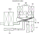
Fig. 9 is an overall configuration diagram showing an example of a defrosting mode of the thermal management system for a vehicle according to the embodiment.
Detailed Description
Hereinafter, embodiments of the refrigeration cycle apparatus will be described with reference to the drawings. The thermal management system 10 for a vehicle shown in fig. 1 is used to adjust various devices or the interior of a vehicle to an appropriate temperature. In the present embodiment, the thermal management system 10 is applied to a hybrid vehicle that obtains a driving force for running the vehicle from an engine (for example, an internal combustion engine) and a motor for running.
The hybrid vehicle of the present embodiment is configured as an external power outlet charging type hybrid vehicle that can charge a battery (for example, an in-vehicle battery) mounted on the vehicle with electric power supplied from an external power supply (for example, a commercial power supply) when the vehicle is parked. As the battery, for example, a lithium ion battery can be used.
The driving force output from the engine is used not only for running of the vehicle but also for operating the generator. Further, the electric power generated by the generator and the electric power supplied from the external power supply can be stored in the battery, and the electric power stored in the battery can be supplied not only to the traveling motor but also to various in-vehicle devices including the electric configuration device constituting the thermal management system 10.
As shown in fig. 1, the thermal management system 10 has: a first pump 11, a second pump 12, a radiator 13, a cooling water cooler 14, a cooling water heater 15, a cooler core 16, a heater core 17, a first switching valve 18, and a second switching valve 19.
The first pump 11 and the second pump 12 are electric pumps that suck in and discharge cooling water. The cooling water is a fluid as a heat medium. In the present embodiment, as the cooling water, a liquid containing at least ethylene glycol, dimethylpolysiloxane, or a nanofluid, or an antifreeze liquid is used.
The radiator 13 is a cooling water outside air heat exchanger that exchanges heat between the cooling water and air outside the vehicle (hereinafter referred to as outside air). The radiator 13 exchanges sensible heat between the cooling water and the outside air. By passing cooling water having a temperature equal to or higher than the temperature of the outside air through the radiator 13, heat can be radiated from the cooling water to the outside air. By passing cooling water at the temperature of the outside air or lower through the radiator 13, the cooling water can absorb heat from the outside air. For example, the radiator 13 can function as a radiator that radiates heat from the cooling water to the outside air, and as a heat absorber that absorbs heat from the outside air from the cooling water.
The radiator 13 is a heat transfer device having a flow path through which cooling water flows and which transfers heat to the cooling water whose temperature has been adjusted by the cooling water cooler 14 and the cooling water heater 15.
The outdoor fan 20 is an electric fan that blows outside air to the radiator 13. The radiator 13 and the outdoor fan 20 are disposed at the forefront of the vehicle. Therefore, the traveling wind can be made to hit the radiator 13 when the vehicle travels.
The cooling water cooler 14 and the cooling water heater 15 are heat exchangers for adjusting the temperature of the cooling water by exchanging heat with the cooling water. The cooling water cooler 14 is a cooling water cooling heat exchanger that cools cooling water. The cooling water heater 15 is a cooling water heating heat exchanger that heats cooling water.
The cooling water cooler 14 is a low-pressure side heat exchanger that absorbs heat from the cooling water by exchanging heat between the low-pressure side refrigerant of the refrigeration cycle 21 and the cooling water. The cooling water heater 15 is a high-pressure side heat exchanger that radiates heat from the high-pressure side refrigerant to the cooling water by exchanging heat between the high-pressure side refrigerant of the refrigeration cycle 21 and the cooling water.
The refrigeration cycle 21 is a vapor compression refrigerator having a compressor 22, a cooling water heater 15, a receiver not shown, an expansion valve 24, and a cooling water cooler 14. In the refrigeration cycle 21 of the present embodiment, a freon refrigerant is used as the refrigerant, and a subcritical refrigeration cycle in which the high-pressure side refrigerant pressure does not exceed the critical pressure of the refrigerant is configured.
The compressor 22 is an electric compressor driven by electric power supplied from a battery, and sucks and compresses the refrigerant of the refrigeration cycle 21 to discharge the refrigerant. The cooling water heater 15 is a condenser that condenses the high-pressure side refrigerant discharged from the compressor 22 by exchanging heat between the high-pressure side refrigerant and the cooling water. That is, in the cooling water heater 15, the high-pressure side refrigerant changes its latent heat.
The receiver, not shown, is a gas-liquid separator that separates the two-phase gas-liquid refrigerant flowing out of the cooling water heater 15 into a gas-phase refrigerant and a liquid-phase refrigerant, and causes the separated liquid-phase refrigerant to flow out toward the expansion valve 24. The expansion valve 24 is a decompression portion for decompressing and expanding the liquid-phase refrigerant flowing out of the receiver 23.
The expansion valve 24 has a temperature sensing portion 24 a. The temperature sensing unit 24a detects the degree of superheat of the refrigerant on the outlet side of the cooling water cooler 14 based on the temperature and pressure of the refrigerant on the outlet side of the cooling water cooler 14. The expansion valve 24 is a temperature type expansion valve. The thermal expansion valve adjusts the throttle passage area by a mechanical mechanism so that the degree of superheat of the refrigerant on the outlet side of the cooling water cooler 14 falls within a predetermined range.
The temperature sensing unit 24a may be formed of a thermistor, or may be an electric expansion valve whose throttle passage area is adjusted by an electric mechanism so that the degree of superheat of the refrigerant on the outlet side of the cooling water cooler 14 falls within a predetermined range.
The cooling water cooler 14 is an evaporator that evaporates the low-pressure refrigerant after being decompressed and expanded by the expansion valve 24 by exchanging heat with cooling water. That is, in the cooling water cooler 14, the latent heat of the low-pressure refrigerant changes. The gas-phase refrigerant evaporated by the cooling water cooler 14 is sucked into the compressor 22 and compressed.
The radiator 13 cools the cooling water by the outside air, whereas the cooling water cooler 14 cools the cooling water by the low-pressure refrigerant of the refrigeration cycle 21. Therefore, the temperature of the cooling water cooled by the cooling water cooler 14 can be made lower than the temperature of the cooling water cooled by the radiator 13. Specifically, the radiator 13 cannot cool the cooling water to a temperature lower than the temperature of the outside air, whereas the cooling water cooler 14 can cool the cooling water to a temperature lower than the temperature of the outside air.
The cooler core 16 and the heater core 17 are heat medium air heat exchangers that adjust the temperature of the feed air by exchanging heat between the cooling water adjusted in temperature by the cooling water cooler 14 and the cooling water heater 15 and the feed air blown into the vehicle interior. The cooler core 16 and the heater core 17 are heat medium circulating devices through which a heat medium circulates.
The cooler core 16 is an air-cooling heat exchanger that cools the air blown into the vehicle interior by exchanging heat between the cooling water and the air blown into the vehicle interior. In the cooler core 16, the cooling water performs sensible heat exchange with the blast air blown into the vehicle interior. The heater core 17 is an air heating heat exchanger that heats the air blown into the vehicle interior by exchanging heat (sensible heat exchange) between the air blown into the vehicle interior and the cooling water. In the heater core 17, the blowing air blown into the vehicle interior performs sensible heat exchange with the cooling water.
The first pump 11 is disposed in the first pump flow path 31. The first pump flow path 31 is provided with a cooling water cooler 14 on the discharge side of the first pump 11.
The second pump 12 is disposed in the second pump flow path 32. The second pump flow path 32 is provided with a coolant heater 15 on the discharge side of the second pump 12.
The heat sink 13 is disposed in the heat sink flow path 33. The cooler core 16 is disposed in the cooler core flow path 36. The heater core 17 is disposed in the heater core flow path 37.
The first pump flow path 31, the second pump flow path 32, and the radiator flow path 33 are connected to the first switching valve 18 and the second switching valve 19. The first switching valve 18 and the second switching valve 19 are switching portions that switch the flow of the cooling water.
The first switching valve 18 has a first inlet 18a and a second inlet 18b as inlets of the cooling water. The first switching valve 18 has a first outlet 18c as an outlet of the cooling water. The second switching valve 19 has a first outlet 19a and a second outlet 19b as outlets of the cooling water. The second switching valve 19 has a first inlet 19c as an inlet of the cooling water.
The first inlet 18a of the first switching valve 18 is connected to one end of the first pump flow path 31. For example, the first inlet 18a of the first switching valve 18 is connected to the cooling water outlet side of the cooling water cooler 14.
The second inlet 18b of the first switching valve 18 is connected to one end of the second pump flow path 32. For example, the second inlet 18b of the first switching valve 18 is connected to the cooling water outlet side of the cooling water heater 15.
The first outlet 18c of the first switching valve 18 is connected to one end of the radiator flow path 33. For example, the first outlet 18c of the first switching valve 18 is connected to the cooling water inlet side of the radiator 13.
The first outlet 19a of the second switching valve 19 is connected to the other end of the first pump flow path 31. For example, the first outlet 19a of the second switching valve 19 is connected to the cooling water intake side of the first pump 11.
The second outlet 19b of the second switching valve 19 is connected to the other end of the second pump flow path 32. For example, the second outlet 19b of the second switching valve 19 is connected to the cooling water suction side of the second pump 12.
The first inlet 19c of the second switching valve 19 is connected to the other end of the radiator flow path 33. For example, the first inlet 19c of the second switching valve 19 is connected to the cooling water outlet side of the radiator 13.
The first switching valve 18 and the second switching valve 19 are configured to be capable of arbitrarily or selectively switching the communication state between each inlet and each outlet.
The cooler core 16 and the heater core 17 are housed in a casing 51 of an indoor air conditioning unit 50 of the vehicle air conditioning device.
The housing 51 forms an air passage for the blowing air to be blown into the vehicle interior, and is molded from a resin (e.g., polypropylene) having a certain degree of elasticity and excellent strength. An inside/outside air switching box 52 is disposed on the most upstream side of the air flow in the casing 51. The inside/outside air switching box 52 is an inside/outside air introducing portion that switches between air in the vehicle interior (hereinafter referred to as inside air) and outside air.
The inside/outside air switching box 52 has an inside air inlet 52a for introducing inside air into the casing 51 and an outside air inlet 52b for introducing outside air. Inside the inside/outside air switching box 52, an inside/outside air switching door 53 is disposed.
The inside/outside air switching door 53 is an air volume ratio changing unit that changes the air volume ratio of the inside air volume to the outside air volume introduced into the casing 51. Specifically, the inside/outside air switching door 53 continuously adjusts the opening areas of the inside air inlet 52a and the outside air inlet 52b, thereby changing the air volume ratio of the inside air volume to the outside air volume. The inside/outside air switching door 53 is driven by an electric actuator, not shown.
An indoor fan 54 (e.g., a blower) is disposed on the downstream side of the air flow of the inside/outside air switching box 52. The indoor fan 54 is a fan that blows air (i.e., inside air and outside air) sucked through the inside/outside air switching box 52 toward the vehicle interior. The indoor blower 54 is an electric blower that drives a centrifugal multi-blade fan (for example, a sirocco fan) by a motor.
In the casing 51, the cooler core 16 and the heater core 17 are disposed on the downstream side of the indoor air-sending device 54 in the air flow.
A heater core bypass passage 51a is formed in the housing 51 at a downstream side of the cooler core 16 in the air flow. The heater core bypass passage 51a is an air passage through which the air having passed through the cooler core 16 flows so as not to pass through the heater core 17.
An air mix door 55 is disposed inside the casing 51 between the cooler core 16 and the heater core 17.
The air mix door 55 is an air volume ratio adjusting unit that continuously changes the air volume ratio between the air flowing into the heater core 17 and the air flowing into the heater core bypass passage 51 a. The air mix door 55 is a rotatable plate-shaped door, a slidable door, or the like, and is driven by an electric actuator not shown.
The temperature of the blown air blown into the vehicle interior is changed in accordance with the air volume ratio of the air passing through the heater core 17 and the air passing through the heater core bypass passage 51 a. Therefore, the air mix door 55 is a temperature adjustment unit that adjusts the temperature of the blown air blown into the vehicle interior.
An air outlet 51b is disposed in the most downstream portion of the air flow of the casing 51, and the air outlet 51b blows out the blown air into the vehicle interior, which is the air-conditioned space. Specifically, the defroster air outlet, the face air outlet, and the foot air outlet are provided as the air outlet 51 b.
The defroster air outlet blows out the conditioned air toward the inner surface of the vehicle windshield. The face air outlet blows out the air-conditioned air toward the upper body of the passenger. The foot air outlet blows out the air conditioning air toward the feet of the occupant.
An air outlet mode door, not shown, is disposed on the air flow upstream side of the air outlet 51 b. The outlet mode door is an outlet mode switching unit that switches the outlet mode. The outlet mode door is driven by an electric actuator not shown.
Examples of the air outlet modes switched by the air outlet mode door include a face mode, a bi-level mode, a foot mode, and a foot defrost mode.
The face mode is an air outlet mode in which the face air outlet is fully opened and air is blown out from the face air outlet toward the upper body of a passenger in the vehicle compartment. The two-stage mode is an air outlet mode in which both the face air outlet and the foot air outlet are opened to blow air toward the upper body and the foot of the occupant in the vehicle compartment.
The foot mode is an air outlet mode in which the foot air outlet is fully opened and the defroster air outlet is opened only at a small opening degree, and air is blown out mainly from the foot air outlet. The foot defroster mode is an air outlet mode in which the foot air outlet and the defroster air outlet are opened to the same degree and air is blown out from both the foot air outlet and the defroster air outlet.
The thermal management system 10 also has in- vehicle devices 81A, 81B, 81C. The in- vehicle devices 81A, 81B, and 81C are a battery temperature adjusting heat exchanger 81A, an inverter 81B, and an engine cooling heat exchanger 81C. The battery temperature adjusting heat exchanger 81A, the inverter 81B, and the engine cooling heat exchanger 81C are heat transfer devices that have a flow path through which cooling water flows and that transfer heat to and from the cooling water. The battery temperature adjusting heat exchanger 81A, the inverter 81B, and the engine cooling heat exchanger 81C are heat generating devices that generate heat in accordance with operations.
The battery temperature adjusting heat exchanger 81A is a heat exchanger that is disposed in an air blowing path toward the battery and exchanges heat between the air and the cooling water. The battery temperature adjusting heat exchanger 81A is disposed in the battery heat exchange flow path 80A.
One end of the battery heat-exchange flow path 80A is connected to the battery heat-exchange outlet 18f of the first switching valve 18. The other end of the battery heat-exchange flow path 80A is connected to the battery heat-exchange inlet 19f of the second switching valve 19.
The inverter 81B is a power conversion device that converts dc power supplied from the battery into ac voltage and outputs the ac voltage to the electric motor for running. The inverter 81B is disposed in the inverter passage 80B.
One end of the inverter flow path 80B is connected to the inverter outlet 18g of the first switching valve 18. The other end of the inverter flow path 80B is connected to the inverter inlet 19g of the second switching valve 19.
The engine cooling heat exchanger 81C is a heat exchanger (e.g., a heat medium heat exchanger) that exchanges heat between the cooling water of the thermal management system 10 (i.e., the cooling water circulated by the first pump 11 or the second pump 12) and the cooling water of the engine cooling circuit 90 (e.g., the engine heat medium). The engine cooling heat exchanger 81C is disposed in the heat exchanger flow path 80C.
One end of the heat exchanger flow path 80C is connected to the heat exchanger outlet 18h of the first switching valve 18. The other end of the heat exchanger flow path 80C is connected to the heat exchanger inlet 19h of the second switching valve 19.
In the present embodiment, one end of the cooler-core flow path 36 is connected to the cooler-core outlet 18i of the first switching valve 18. The other end of the cooler-core flow path 36 is connected to the cooler-core inlet 19i of the second switching valve 19.
One end of the heater core flow path 37 is connected to the heater core outlet 18j of the first switching valve 18. The other end of the heater core flow path 37 is connected to the heater core inlet 19j of the second switching valve 19.
The first switching valve 18 switches the following states for the respective devices 13, 16, 17, 81A, 81B, and 81C connected to the outlet side: a state in which the cooling water discharged from the first pump 11 flows in, a state in which the cooling water discharged from the second pump 12 flows in, and a state in which the cooling water discharged from the first pump 11 and the cooling water discharged from the second pump 12 do not flow in.
The second switching valve 19 switches the following states for the respective devices 13, 16, 17, 81A, 81B, and 81C connected on the inlet side: a state in which the cooling water flows out to the first pump 11, a state in which the cooling water flows out to the second pump 12, and a state in which the cooling water does not flow out to the first pump 11 and the second pump 12.
The first switching valve 18 and the second switching valve 19 can adjust the valve opening degree. This enables adjustment of the flow rate of the cooling water flowing through each of the devices 13, 16, 17, 81A, 81B, and 81C.
The first switching valve 18 and the second switching valve 19 can mix the cooling water discharged from the first pump 11 and the cooling water discharged from the second pump 12 at an arbitrary flow rate ratio and flow the mixed cooling water into the devices 13, 16, 17, 81A, 81B, and 81C.
The engine cooling circuit 90 is a cooling water circulation circuit for cooling the engine 91. The engine cooling circuit 90 has a circulation flow path 92 through which cooling water circulates. The engine 91, the third pump 93, the engine radiator 94, and the engine cooling heat exchanger 81C are disposed in the circulation flow path 92.
The third pump 93 is an electric pump that sucks and discharges cooling water. The third pump 93 may be a mechanical pump driven by power output from the engine 91.
The engine radiator 94 is a heat exchanger for radiating heat of the cooling water to the outside air by exchanging heat between the cooling water and the outside air.
The circulation flow path 92 is connected to a radiator bypass flow path 95. The radiator bypass flow path 95 is a flow path through which the cooling water flows by bypassing the engine radiator 94.
A thermostat 96 is disposed at a connection portion between the radiator bypass passage 95 and the circulation passage 92. The thermostat 96 is a cooling water temperature responsive valve constituted by a mechanical mechanism that opens and closes a cooling water flow path by displacing a valve body with a thermostatic wax (e.g., a heat sensitive member) that changes in volume due to temperature.
Specifically, the thermostat 96 closes the radiator bypass passage 95 when the temperature of the cooling water exceeds a predetermined temperature (for example, 80 ℃ or higher), and opens the radiator bypass passage 95 when the temperature of the cooling water is lower than the predetermined temperature (for example, less than 80 ℃).
The circulation flow passage 92 is connected to an engine auxiliary passage 97. The engine auxiliary passage 97 is a passage through which the cooling water flows in parallel with the engine cooling heat exchanger 81C. An engine auxiliary 98 is disposed in the engine auxiliary flow passage 97. The engine auxiliary 98 is an oil heat exchanger, an EGR cooler, a throttle cooler, a turbo cooler, an engine assist motor, or the like. The oil heat exchanger is a heat exchanger that exchanges heat between engine oil or transmission oil and cooling water to adjust the temperature of the oil.
The EGR cooler is a heat exchanger constituting an EGR device (i.e., an exhaust gas recirculation device) that recirculates a part of exhaust gas of an engine to an intake side to reduce pumping loss by a throttle valve, and is a heat exchanger that exchanges heat between the recirculated gas and cooling water to adjust the temperature of the recirculated gas.
The throttle cooler is a water jacket provided inside the throttle valve to cool the throttle valve.
The turbo cooler is a cooler for cooling the turbocharger by exchanging heat generated by the turbocharger with cooling water.
The engine assist motor is a large motor for rotating an engine belt even when the engine is stopped, and is used for starting the engine by operating a compressor, a water pump, or the like driven by the engine belt even in a state where there is no driving force of the engine.
The engine radiator 94 is connected to the first reserve tank 99. The first reserve tank 99 is an air-release type container that stores cooling water. Therefore, the pressure on the liquid surface of the cooling water accumulated in first reserve tank 99 is atmospheric pressure. The pressure of the liquid surface of the coolant stored in the first storage tank 99 may be a predetermined pressure different from the atmospheric pressure in the first storage tank 99.
By storing excess cooling water in the first reserve tank 99, it is possible to suppress a decrease in the amount of cooling water circulating through each flow path. The first reserve tank 99 has a function of separating gas and liquid from bubbles mixed in the cooling water.
The radiator flow path 33 is connected to the second reserve tank 100. Second reserve tank 100 is identical in construction and function to first reserve tank 99.
An auxiliary heater 101 is disposed in a casing 51 of an indoor air conditioning unit 50 of a vehicle air conditioning device at a downstream side of a heater core 17 in an air flow. The auxiliary heater 101 is a PTC heater (e.g., an electric heater) having a PTC element (e.g., a positive temperature coefficient thermistor) that heats air by supplying electric power to the PTC element to generate heat. The operation (for example, the amount of heat generation) of the auxiliary heater 101 is controlled by the control device 60.
The refrigeration cycle 21 has an internal heat exchanger 102. The internal heat exchanger 102 is a heat exchanger that exchanges heat between the refrigerant flowing out of the cooling water heater 15 and the refrigerant flowing out of the cooling water cooler 14.
Next, an electric control unit of the thermal management system 10 will be described with reference to fig. 2. The control device 60 is a control unit including a known microcomputer including a CPU, a ROM, a RAM, and the like, and peripheral circuits thereof, and performs various calculations and processes based on an air conditioning control program stored in the ROM to control the operation of various devices to be controlled connected to an output side.
The devices to be controlled by the control device 60 are electric actuators and the like that drive the first pump 11, the second pump 12, the first switching valve 18, the second switching valve 19, the outdoor fan 20, the compressor 22, the indoor fan 54, and various doors (for example, the inside/outside air switching door 53, the air mixing door 55, the outlet mode door, and the like) disposed inside the casing 51.
The control device 60 is an integrated control unit that controls various devices to be controlled connected to the output side thereof. Hardware and software for controlling the operation of each control target device in the control device 60 constitute a control unit for controlling the operation of each control target device.
The hardware and software for controlling the operations of the first pump 11 and the second pump 12 in the control device 60 is a pump control unit 60 a. The pump control unit 60a is a flow rate control unit that controls the flow rate of the cooling water flowing through the radiator 13. The pump control unit 60a may be configured independently of the control device 60.
The switching valve control unit 60b is hardware and software for controlling the operations of the first switching valve 18 and the second switching valve 19 in the control device 60. The switching valve control unit 60b is a flow rate control unit that adjusts the flow rate of the cooling water flowing through the radiator 13. The switching valve control unit 60b may be configured independently of the control device 60.
The hardware and software for controlling the operation of the compressor 22 in the control device 60 is a compressor control unit 60 c. The compressor controller 60c is a refrigerant flow rate adjuster that controls the flow rate of the refrigerant discharged from the compressor 22. The compressor controller 60c may be configured independently of the controller 60.
Detection signals of sensor groups such as the inside air sensor 61, the outside air sensor 62, the solar radiation sensor 63, the first water temperature sensor 64, the second water temperature sensor 65, the cooler core temperature sensor 66, the refrigerant temperature sensor 67, the radiator water temperature sensor 111, the battery temperature sensor 112, the inverter temperature sensor 113, the engine water temperature sensor 114, and the refrigerant pressure sensor 115 are input to the input side of the control device 60.
The inside air sensor 61 is an inside air temperature detecting unit that detects the temperature of the inside air. The outside air sensor 62 is an outside air temperature detection unit that detects the temperature of the outside air. The insolation sensor 63 is an insolation amount detection unit that detects an amount of insolation in the vehicle interior.
The first water temperature sensor 64 is a first water temperature detector that detects the temperature of the coolant flowing through the first pump flow path 31 (e.g., the temperature of the coolant drawn into the first pump 11).
The second water temperature sensor 65 is a second water temperature detector that detects the temperature of the coolant flowing through the second pump flow path 32 (e.g., the temperature of the coolant drawn into the second pump 12). The second water temperature sensor 65 is a detector that detects a physical quantity related to the temperature Th of the cooling water circulating through the cooling water heater 15.
The cooler core temperature sensor 66 is a cooler core temperature detecting unit that detects the surface temperature of the cooler core 16. The cooler core temperature sensor 66 is, for example, a fin thermistor that detects the temperature of a heat exchange fin of the cooler core 16, a water temperature sensor that detects the temperature of cooling water flowing through the cooler core 16, or the like.
The refrigerant temperature sensors 67 are a discharge-side refrigerant temperature sensor 67A and a suction-side refrigerant temperature sensor 67B. The discharge-side refrigerant temperature sensor 67A is a refrigerant temperature detecting unit that detects the temperature of the refrigerant discharged from the compressor 22. The suction-side refrigerant temperature sensor 67B is a refrigerant temperature detecting unit that detects the temperature of the refrigerant sucked into the compressor 22.
The radiator water temperature sensor 111 is a water temperature detecting unit that detects the temperature of the cooling water flowing through the radiator flow path 33 (for example, the temperature of the cooling water flowing out of the radiator 13).
The battery temperature sensor 112 is a battery temperature detection unit that detects the temperature of the cooling water flowing through the battery heat exchange flow path 80A (e.g., the temperature of the cooling water flowing into the battery temperature adjustment heat exchanger 81A).
The inverter temperature sensor 113 is an inverter temperature detection unit that detects the temperature of the cooling water flowing through the inverter flow path 80B (e.g., the temperature of the cooling water flowing out of the inverter 81B).
The engine water temperature sensor 114 is a water temperature detector that detects the temperature of the cooling water circulating through the engine cooling circuit 90 (for example, the temperature of the cooling water flowing through the inside of the engine 91).
The refrigerant pressure sensors 115 are a discharge-side refrigerant pressure sensor 115A and a suction-side refrigerant pressure sensor 115B. The discharge-side refrigerant pressure sensor 115A is a refrigerant pressure detecting unit that detects the pressure of the refrigerant discharged from the compressor 22. The suction-side refrigerant pressure sensor 115B is a refrigerant pressure detecting unit that detects the pressure of the refrigerant sucked into the compressor 22.
To the input side of the control device 60, operation signals from various air-conditioning operation switches provided on an operation panel 69 disposed near an instrument panel disposed in the front portion of the vehicle interior are input. As various air-conditioning operation switches provided on the operation panel 69, an air-conditioning switch, an automatic switch, an air volume setting switch of the indoor air-sending device 54, a vehicle indoor temperature setting switch, and the like are provided.
The air conditioning switch is a switch for switching between operation and stop (in other words, on and off) of air conditioning (i.e., cooling or heating). The automatic switch is a switch for setting or releasing automatic control of the air conditioner. The vehicle interior temperature setting switch is a target temperature setting unit that sets a target temperature in the vehicle interior by an operation of an occupant.
Next, the operation of the above-described structure will be described. The controller 60 switches the mode in which the cooling water flows to the various modes shown in fig. 3 to 7 by operating the first switching valve 18 and the second switching valve 19. For ease of understanding, thermal management system 10 is shown in simplified illustration in fig. 3-7.
In the outside air heat absorption heat pump mode shown in fig. 3, the radiator 13 is connected to the cooling water cooler 14, the heater core 17 is connected to the cooling water heater 15, and the engine cooling heat exchanger 81C is not connected to either the cooling water cooler 14 or the cooling water heater 15.
Thus, since the cooling water cooled by the cooling water cooler 14 and having a low temperature lower than the outside air temperature flows through the radiator 13, the cooling water absorbs heat from the outside air at the radiator 13, and since the cooling water heated by the cooling water heater 15 flows through the heater core 17, the blowing air blown into the vehicle interior is heated at the heater core 17.
That is, in the outdoor heat absorption heat pump mode, the refrigerant of the refrigeration cycle 21 absorbs heat from the outdoor air by the radiator 13 and radiates heat to the cooling water by the cooling water heater 15. Therefore, the heat pump operation that extracts the heat of the outside air can be realized.
In the engine heat absorption heat pump mode shown in fig. 4, the engine cooling heat exchanger 81C is connected to the cooling water cooler 14, the heater core 17 is connected to the cooling water heater 15, and the radiator 13 is disconnected from both the cooling water cooler 14 and the cooling water heater 15.
Thus, since the cooling water heated in the engine-cooling heat exchanger 81C flows through the cooling water cooler 14, the cooling water is absorbed by the refrigerant in the cooling water cooler 14, and since the cooling water heated in the cooling water heater 15 flows through the heater core 17, the blowing air blown into the vehicle interior is heated in the heater core 17.
That is, in the engine heat-absorption heat pump mode, the refrigerant of the refrigeration cycle 21 absorbs heat from the coolant heated in the engine-cooling heat exchanger 81C and releases heat to the coolant in the coolant heater 15. Therefore, the heat pump operation that extracts the heat of the engine 91 can be realized.
In the engine heat absorption heat pump mode, if the other in- vehicle devices 81A and 81B are connected to the coolant cooler 14, the heat of the other in- vehicle devices 81A and 81B can be extracted. Therefore, the engine heat absorption heat pump mode can be expressed as the apparatus heat absorption heat pump mode.
In the auxiliary heat pump mode, the engine heating heat pump mode, the facility heating mode, and the thermal mass utilization heating mode shown in fig. 5, the engine-cooling heat exchanger 81C and the heater core 17 are connected to the coolant heater 15, and the radiator 13 and the coolant cooler 14 are connected.
Thus, since the cooling water heated by the engine cooling heat exchanger 81C flows through the heater core 17, the air blown into the vehicle interior is heated by the heater core 17.
Further, since the cooling water cooled by the cooling water cooler 14 flows through the radiator 13, the cooling water absorbs heat from the outside air at the radiator 13, and since the cooling water heated by the cooling water heater 15 flows through the heater core 17, the air blown into the vehicle interior is heated at the heater core 17.
That is, in the auxiliary heat pump mode, the engine heating heat pump mode, the equipment heating mode, and the thermal mass utilization heating mode, the refrigerant of the refrigeration cycle 21 absorbs heat from the outside air by the radiator 13, and radiates heat to the coolant by the coolant heater 15. Therefore, the heat pump operation that extracts the heat of the outside air can be realized.
Therefore, when the exhaust heat of the engine 91 is still insufficient as the heating heat source, the auxiliary heat pump mode is executed, whereby the heating heat source can be supplemented by the heat pump operation.
When the engine 91 is warmed up, the engine heating heat pump mode is executed to cause the cooling water heated by the cooling water heater 15 to flow through the engine cooling heat exchanger 81C, so that the engine 91 can be heated by the cooling water heater 15.
In the engine-heating heat pump mode, if the other in- vehicle devices 81A and 81B are connected to the cooling water heater 15, the other in- vehicle devices 81A and 81B can be heated by the cooling water heater 15. Therefore, the engine-heating heat pump mode can be expressed as the equipment-heating heat pump mode.
In the device heating mode, the other in- vehicle devices 81A and 81B connected to the cooling water heater 15 can be heated by the heat of the engine 91.
Further, by executing the thermal mass utilization heating mode, the cooling water heated by the cooling water heater 15 flows through the engine-cooling heat exchanger 81C, so that the variation in the cooling water temperature can be suppressed using the thermal mass (for example, heat capacity) of the engine 91.
In the engine waste heat direct use mode shown in fig. 6, the engine cooling heat exchanger 81C and the heater core 17 are connected to each other, and are not connected to both the cooling water cooler 14 and the cooling water heater 15.
Although not shown, a cooling water pump that sucks in and discharges cooling water is disposed in the cooling water flow path between the engine cooling heat exchanger 81C and the heater core 17. Thus, since the cooling water heated by the engine cooling heat exchanger 81C flows through the heater core 17, the air blown into the vehicle interior is heated by the heater core 17.
When the temperature of the cooling water flowing through the heater core 17 exceeds the temperature required for heating the vehicle interior, if the engine-cooling heat exchanger 81C is connected to the heater core 17 and the radiator 13, the excess heat of the engine 91 can be dissipated to the outside air.
In the engine waste heat direct use mode, if another heat generating device (the battery temperature adjusting heat exchanger 81A, the inverter 81B) is connected to the heater core 17, the cooling water heated by the other heat generating device 81A, 81B flows through the heater core 17, and therefore the air blown into the vehicle interior can be heated by the heater core 17. Therefore, the engine waste heat direct utilization mode can be expressed as the plant waste heat direct utilization mode.
In the thermal mass utilization cooling mode shown in fig. 7, the engine-cooling heat exchanger 81C and the radiator 13 are connected to the coolant heater 15, and the cooler core 16 is connected to the coolant cooler 14.
Thus, since the cooling water cooled by the cooling water cooler 14 flows through the cooler core 16, the cooling air blown into the vehicle interior is cooled by the cooler core 16, and since the cooling water heated by the cooling water heater 15 flows through the radiator 13, the heat is radiated from the cooling water to the outside air by the radiator 13.
Further, since the cooling water heated by the cooling water heater 15 flows through the engine 91, the variation in the temperature of the cooling water can be suppressed by the thermal mass of the engine 91, or the increase in the high pressure of the refrigerant can be suppressed by suppressing the increase in the temperature of the cooling water, and thus efficient cooling can be achieved.
Although not shown, the controller 60 may operate the first switching valve 18 and the second switching valve 19 to switch the mode of the cooling water flow to the engine independent mode.
In the engine independent mode, the engine cooling heat exchanger 81C is not connected to both the coolant cooler 14 and the coolant heater 15. Thus, the waste heat of the engine 91 cannot transfer heat to the cooling water cooler 14 and the cooling water heater 15.
For example, during the cooling operation, the engine independent mode is executed when the temperature detected by the engine water temperature sensor 114, that is, the temperature of the cooling water circulating through the engine cooling circuit 90 exceeds a preset reference temperature. This can prevent the cooling performance from being lowered by the influence of the waste heat of the engine 91.
In the above-described modes, when the temperature of the cooling water supplied to the radiator 13 is lower than the dew-point temperature, the condensed water of the radiator 13 freezes to cause frost formation. When the frost is generated on the radiator 13, the amount of heat exchange in the radiator 13 is reduced, and therefore, it is necessary to defrost the radiator 13.
Therefore, control device 60 executes the control processing shown in the flowchart of fig. 8. The control process shown in the flowchart of fig. 8 is executed as a subroutine with respect to the main routine of the thermal management system 10.
In step S100, it is determined whether or not the radiator 13 needs defrosting. In other words, it is determined whether frost is attached to the radiator 13.
For example, the determination as to whether frost is adhering to the radiator 13 is performed based on at least one of the traveling speed of the vehicle, the temperature of the cooling water after heat exchange in the cooling water cooler 14, the pressure of the low-pressure side refrigerant of the refrigeration cycle 21, the time difference between the target outlet temperature TAO of the cabin interior supply air and the actual outlet temperature TAV of the cabin interior supply air, the temperature of the cooling water after heat exchange in the cooling water heater 15, the on/off state of the ignition switch of the vehicle, and the like.
The target outlet air temperature TAO of the cabin air is calculated using, for example, the following equation.
TAO=Kset×Tset-Kr×Tr-Kam×Tam-Ks×As+C
Tset is a vehicle interior set temperature set by a vehicle interior temperature setting switch, Tr is a vehicle interior temperature (interior air temperature) detected by an interior air sensor, Tam is an exterior air temperature detected by an exterior air sensor, and As is an amount of solar radiation detected by a solar radiation sensor. Kset, Kr, Kam, Ks are control gains, and C is a constant for correction.
The actual outlet temperature TAV of the vehicle interior supply air is calculated from, for example, the temperature of the air flowing out of the heater core 17, the opening degree of the air mix door 55, and the like. A temperature sensor that detects an actual outlet temperature TAV of the air blown into the vehicle interior may be provided.
If it is determined in step S100 that defrosting of the radiator 13 is necessary, the process proceeds to step S110, and it is determined whether or not the vehicle is stopped. Specifically, it is determined whether the vehicle is in a stop or not based on a vehicle speed sensor or an ignition switch.
If it is determined in step S110 that the vehicle is stopped, the process proceeds to step S120, and the defrosting mode is switched to the cooling water circuit shown in fig. 9. Specifically, the operations of the first switching valve 18 and the second switching valve 19 are controlled so that the cooling water circulates between the cooling water heater 15 and the radiator 13 as indicated by a thick solid line in fig. 9, and so that the cooling water circulates between the cooling water cooler 14 and at least one of the in- vehicle devices 81A, 81B, and 81C as indicated by a thick one-dot chain line in fig. 9.
Hereinafter, a cooling water circuit in which cooling water circulates between the cooling water heater 15 and the radiator 13 is referred to as a high water temperature circuit. Hereinafter, a cooling water circuit in which cooling water circulates between the cooling water cooler 14 and at least one of the in- vehicle devices 81A, 81B, and 81C is referred to as a low water temperature circuit.
Next, in step S130, the operation of the compressor 22 is controlled in accordance with the cooling water temperature Th of the high water temperature circuit. For example, the control device 60 uses the temperature of the cooling water detected by the second water temperature sensor 65 as the cooling water temperature Th of the high water temperature circuit.
Specifically, as shown in the control diagram of step S130 in fig. 8, the compressor 22 is driven in the high temperature region of the cooling water temperature Th, and the compressor 22 is stopped in the low temperature region of the cooling water temperature Th. In the control map of step S130 of fig. 8, a hysteresis width for preventing control vibration is set.
More specifically, when the cooling water temperature Th rises from the low temperature region to the high temperature region, the compressor 22 is driven when the cooling water temperature Th is higher than the first threshold value Th 1. When the cooling water temperature Th decreases from the high temperature region to the low temperature region, the compressor 22 is stopped when the cooling water temperature Th is lower than the second threshold value Th 2. The first threshold value Th1 and the second threshold value Th2 are stored in the control device 60 in advance. The second threshold value Th2 is a value smaller than the first threshold value Th 1. In this example, the first threshold value Th1 is a value equal to or higher than the freezing point of pure water (i.e., 0 ℃).
Thus, when the cooling water temperature Th is low, the compressor 22 can be driven to increase the cooling water temperature Th. That is, the heat of at least one of the in- vehicle devices 81A, 81B, and 81C can be absorbed from the cooling water cooler 14 side to the cooling water heater 15 side via the cooling water of the low-water-temperature circuit, and the heat can be radiated to the radiator 13 via the cooling water of the high-water-temperature circuit, so that the cooling water temperature Th of the high-water-temperature circuit can be increased.
Further, since the compressor 22 is stopped when the cooling water temperature Th is high, the compressor 22 can be prevented from being excessively driven, and power consumption of the compressor 22 can be reduced.
Next, in step S140, it is determined whether or not the cooling water temperature Th of the high water temperature circuit is higher than a third threshold value Th 3. The third threshold value Th3 is stored in advance in the control device 60. In this example, the third threshold value Th3 is a value equal to or higher than the freezing point of pure water (i.e., 0 ℃).
When it is determined in step S140 that the cooling water temperature Th is higher than the third threshold value Th3, the routine proceeds to step S150, where the operation of at least one of the first switching valve 18, the second switching valve 19, and the second pump 12 is controlled to supply the cooling water to the radiator 13.
This allows the coolant in the high-coolant-temperature circuit to be supplied to the radiator 13, thereby defrosting the radiator 13. When the compressor 22 is stopped in step S130, the evaporator 13 can be defrosted without consuming power in the compressor 22. When the compressor 22 is driven in step S130, the heat of at least one of the in- vehicle devices 81A, 81B, 81C can be used to defrost the radiator 13, and thus the power consumed by the compressor 22 can be suppressed.
On the other hand, when it is determined in step S140 that the cooling water temperature Th is not higher than the third threshold value Th3, the routine proceeds to step S160, and the operation of at least one of the first switching valve 18, the second switching valve 19, and the second pump 12 is controlled so that the cooling water is not supplied to the radiator 13.
Therefore, when the cooling water temperature Th is lower than the third threshold Th3, the flow rate of the cooling water supplied from the cooling water heater 15 to the radiator 13 is reduced as compared with the case where the cooling water temperature Th is higher than the third threshold Th 3.
Thus, when the cooling water temperature Th is low, the supply of cooling water to the radiator 13 is suppressed until the cooling water temperature Th rises to a certain extent, and therefore the cooling water temperature Th can be quickly increased to quickly improve the defrosting capability.
On the other hand, if it is determined in step S100 that defrosting of the radiator 13 is not necessary or if it is determined in step S110 that the vehicle is not stopped, the process proceeds to step S170, where the cooling water circuit switched to the defrosting mode is prohibited. In other words, the mode is switched to a mode in which cooling water flows other than the defrosting mode. Therefore, when defrosting is not necessary in the radiator 13 or while the vehicle is running, defrosting of the radiator 13 is not performed.
In the present embodiment, as described in steps S100, S120, and S130, when it is determined that defrosting of the radiator 13 is necessary, the control device 60 controls the operations of the first switching valve 18 and the second switching valve 19 so that the compressor 22 is driven in a defrosting mode in which the cooling water circulates between the cooling water cooler 14 and the in- vehicle devices 81A, 81B, and 81C and the cooling water circulates between the cooling water heater 15 and the radiator 13.
Thus, the heat of the in- vehicle devices 81A, 81B, and 81C can be extracted from the cooling water cooler 14 side to the cooling water heater 15 side via the cooling water, and further can be radiated to the radiator 13 via the cooling water, so that the radiator 13 can be defrosted by the heat of the in- vehicle devices 81A, 81B, and 81C. Therefore, the power consumed by the compressor 22 can be suppressed and the defrosting of the radiator 13 can be performed.
In the present embodiment, as described in step S120, when it is determined that defrosting of the radiator 13 is necessary, the control device 60 controls the operations of the first switching valve 18 and the second switching valve 19 so that the cooling water circulates between the cooling water cooler 14 and the cooler core 16.
This enables the amount of residual heat in the vehicle compartment to be used as a heat source for defrosting the radiator 13. In the defrosting mode, the air blown into the vehicle interior can be cooled to dehumidify the vehicle interior.
In the present embodiment, as described in step S120, when it is determined that defrosting of the radiator 13 is necessary, the control device 60 controls the operations of the first switching valve 18 and the second switching valve 19 so that the cooling water circulates between the cooling water heater 15 and the heater core 17.
This makes it possible to defrost the radiator 13 and adjust the temperature of the heater core 17 with the cooling water heat-exchanged by the cooling water heater 15. That is, the radiator 13 can be defrosted and the vehicle interior can be heated.
In the present embodiment, as described in step S130, when it is determined that defrosting of the radiator 13 is necessary, the controller 60 controls the operation of the compressor 22 based on the cooling water temperature detected by the second water temperature sensor 65.
Thus, the operation of the compressor 22 can be controlled in accordance with the temperature of the cooling water supplied to the radiator 13, and therefore, the power consumed by the compressor 22 can be suppressed and the radiator 13 can be defrosted.
In the present embodiment, as described in step S130, the controller 60 stops the compressor 22 when determining that defrosting of the radiator 13 is necessary and when determining that the temperature of the cooling water circulating through the cooling water heater 15 is higher than the first threshold Th1 based on the temperature of the cooling water detected by the second water temperature sensor 65.
Thus, the heat of the cooling water circulating through the cooling water heater 15 is utilized to defrost the radiator 13 without driving the compressor 22, and thus the power consumed by the compressor 22 can be further suppressed.
In the present embodiment, the first threshold Th1 is a value equal to or higher than the freezing point of pure water. This enables the radiator 13 to be defrosted reliably by the heat of the cooling water circulating through the cooling water heater 15.
In the present embodiment, as described in step S130, the controller 60 stops the compressor 22 when it is determined that the temperature of the cooling water circulating through the cooling water heater 15 has increased to be higher than the first threshold value Th1 based on the temperature of the cooling water detected by the second water temperature sensor 65. The controller 60 drives the compressor 22 when determining that the temperature of the cooling water circulating through the cooling water heater 15 is lower than the second threshold Th2 based on the temperature of the cooling water detected by the second water temperature sensor 65.
Thus, when the temperature of the cooling water circulating through the cooling water heater 15 is high, the heat of the cooling water circulating through the cooling water heater 15 can be used to defrost the radiator 13 without driving the compressor 22. When the cooling water circulating through the cooling water heater 15 has a small amount of heat, the compressor 22 is driven, and the heat of the in- vehicle devices 81A, 81B, and 81C can be used to defrost the radiator 13.
In the present embodiment, as described in steps S140 to S160, when it is determined that defrosting of the radiator 13 is necessary and when it is determined that the temperature of the cooling water circulating through the cooling water heater 15 is lower than the third threshold Th3 based on the temperature of the cooling water detected by the second water temperature sensor 65, the control device 60 controls the operation of at least one of the first switching valve 18, the second switching valve 19, and the second pump 12 so that the flow rate of the cooling water supplied from the cooling water heater 15 to the radiator 13 is reduced, as compared with the case where it is determined that the temperature of the cooling water circulating through the cooling water heater 15 is higher than the third threshold Th3 based on the temperature of the cooling water detected by the second water temperature sensor 65.
Thus, when the temperature Th of the cooling water circulating through the cooling water heater 15 is low and the defrosting capability is low, heat radiation from the radiator 13 is suppressed, and therefore the temperature Th of the cooling water circulating through the cooling water heater 15 can be increased as early as possible to improve the defrosting capability.
In the present embodiment, the third threshold Th3 is equal to or less than the first threshold. Thus, the compressor 22 can be stopped after the temperature Th of the cooling water circulating through the cooling water heater 15 has become high and the defrosting capability has become high, and therefore, it is possible to reliably achieve defrosting of the radiator 13 while suppressing the power consumed by the compressor 22.
Preferably, the third threshold value Th3 is equal to the first threshold value Th 1. Since the compressor 22 is immediately stopped when the temperature Th of the cooling water circulating through the cooling water heater 15 becomes high and the defrosting capability becomes high, the power consumed by the compressor 22 can be suppressed as much as possible and the radiator 13 can be defrosted.
In the present embodiment, as described in steps S140 to S160, when it is determined that defrosting of the radiator 13 is necessary and when it is determined that the temperature of the cooling water circulating through the cooling water heater 15 is lower than the third threshold Th3 based on the temperature of the cooling water detected by the second water temperature sensor 65, the controller 60 controls the operation of at least one of the first switching valve 18, the second switching valve 19, and the second pump so as to stop the supply of the cooling water from the cooling water heater 15 to the radiator 13. When it is determined that the temperature of the cooling water circulating through the cooling water heater 15 is higher than the third threshold Th3 based on the temperature of the cooling water detected by the second water temperature sensor 65, the controller 60 controls the operation of at least one of the first switching valve 18, the second switching valve 19, and the second pump so that the cooling water is supplied from the cooling water heater 15 to the radiator 13.
Thus, when the temperature Th of the cooling water circulating through the cooling water heater 15 is low and the defrosting capability is low, the heat radiation of the radiator 13 is further suppressed, and therefore the temperature Th of the cooling water circulating through the cooling water heater 15 can be further increased at an early stage to improve the defrosting capability.
In the present embodiment, the third threshold Th3 is equal to or higher than the freezing point of pure water. This can suppress heat radiation from the radiator 13 when defrosting is not possible.
In the present embodiment, the in- vehicle devices 81A, 81B, and 81C generate heat in accordance with the operation. This enables the waste heat of the in- vehicle devices 81A, 81B, and 81C to be effectively used to defrost the radiator 13, and thus enables the defrosting capability of the radiator 13 to be improved while suppressing the power consumed by the compressor 22.
In the present embodiment, as described in steps S110 and S170, even when it is determined that defrosting of the radiator 13 is necessary, the control device 60 controls the operation of the first switching valve 18 and the second switching valve 19 so as to prohibit the execution of the defrosting mode when the vehicle is traveling.
Thus, since defrosting is not performed during traveling, the heat generated by the cooling water heater 15 is radiated to the outside by traveling wind in the radiator 13, and a decrease in defrosting performance can be suppressed.
(other embodiments)
The above embodiment can be variously modified as follows, for example.
(1) In the above embodiment, the controller 60 uses the temperature of the cooling water detected by the second water temperature sensor 65 as the cooling water temperature Th of the high water temperature circuit, but the controller 60 may estimate the cooling water temperature Th of the high water temperature circuit from a physical quantity related to the temperature of the cooling water circulating through the cooling water heater 15.
(2) In the above embodiment, the control device 60 supplies the cooling water to the radiator 13 in step S150 and does not supply the cooling water to the radiator 13 in step S160, but the control device 60 may set the flow rate of the cooling water supplied to the radiator 13 to a high flow rate in step S150 and set the flow rate of the cooling water supplied to the radiator 13 to a low flow rate in step S160.
(3) In the above embodiment, the cooler core 16 and the heater core 17 are provided as the heat medium circulating device, but other various in-vehicle devices may be provided as the heat medium circulating device. In the defrosting mode of this configuration, the temperature of various other in-vehicle devices can be managed while defrosting the radiator 13.
(4) In the above embodiments, the cooling water is used as the heat medium, but various media such as oil may be used as the heat medium.
Nanofluids may also be used as the thermal medium. The nanofluid is a fluid in which nanoparticles having a nanometer particle size are mixed. By mixing the nanoparticles into the heat medium, the following effects can be obtained in addition to the effect of the antifreeze solution obtained by lowering the freezing point as in the case of the cooling water using ethylene glycol.
That is, an effect of improving the thermal conductivity in a specific temperature range, an effect of increasing the heat capacity of the heat medium, an effect of preventing corrosion of the metal pipes or deterioration of the rubber pipes, and an effect of improving the fluidity of the heat medium at an extremely low temperature can be obtained.
Such action and effect vary variously depending on the particle structure, particle shape, mixing ratio, and additional substance of the nanoparticles.
This can improve the heat conductivity, and therefore, even a small amount of the heat medium as compared with the cooling water using ethylene glycol can obtain the same cooling effect.
Further, since the heat capacity of the thermal medium can be increased, the amount of cold storage heat generated by sensible heat of the thermal medium itself can be increased.
By increasing the cold heat storage amount, even in a state where the compressor 22 is not operated, the temperature control for cooling or heating the device using the cold heat storage amount can be performed for a certain period of time, and therefore, the vehicle thermal management device can be made more power-saving.
The aspect ratio of the nanoparticles is preferably 50 or more. This is because sufficient thermal conductivity can be obtained. The aspect ratio is a shape index indicating a ratio of the longitudinal direction x the lateral direction of the nanoparticle.
As the nanoparticles, any substance including Au, Ag, Cu, and C can be used. Specifically, as the structural atoms of the nanoparticles, Au nanoparticles, Ag nanowires, CNTs, graphene, graphite core-shell type nanoparticles, CNTs containing Au nanoparticles, and the like can be used.
CNTs are carbon nanotubes. The graphite core-shell type nanoparticles are particles in which a structural body such as a carbon nanotube is present so as to surround the atoms.
(5) In the refrigeration cycle 21 of each of the above embodiments, a freon refrigerant is used as the refrigerant, but the type of the refrigerant is not limited thereto, and a natural refrigerant such as carbon dioxide, a hydrocarbon refrigerant, or the like may be used.
The refrigeration cycle 21 of each of the above embodiments constitutes a subcritical refrigeration cycle in which the high-pressure side refrigerant pressure does not exceed the critical pressure of the refrigerant, but may constitute a supercritical refrigeration cycle in which the high-pressure side refrigerant pressure exceeds the critical pressure of the refrigerant.
Claims (21)
1. A refrigeration cycle apparatus, comprising:
a compressor (22) that sucks and discharges refrigerant;
a high-pressure side heat exchanger (15) that exchanges heat between the high-pressure refrigerant discharged from the compressor and a heat medium;
a decompression unit (24) that decompresses the refrigerant that has exchanged heat in the high-pressure side heat exchanger;
a low-pressure side heat exchanger (14) that exchanges heat between the low-pressure refrigerant decompressed by the decompression unit and the heat medium;
a first pump (11) that sucks in and discharges the heat medium circulating in the low-pressure-side heat exchanger;
a second pump (12) that sucks in and discharges the heat medium circulating in the high-pressure-side heat exchanger;
vehicle-mounted devices (81A, 81B, 81C) through which the heat medium circulates and which supply heat to the heat medium;
a heat medium air heat exchanger (13) that exchanges heat between the heat medium and air;
switching units (18, 19) for switching the following states for the in-vehicle device: the switching unit switches the heat medium air heat exchanger between a state in which the heat medium is circulated between the in-vehicle device and the high-pressure side heat exchanger and a state in which the heat medium is circulated between the in-vehicle device and the low-pressure side heat exchanger, as follows: a state in which the heat medium is circulated between the heat medium air heat exchanger and the high-pressure side heat exchanger, and a state in which the heat medium is circulated between the heat medium air heat exchanger and the low-pressure side heat exchanger;
a control unit (60) that, when it is determined that defrosting of the heat medium air heat exchanger is necessary, controls the operation of the switching unit so as to set a defrosting mode in which the heat medium is circulated between the low-pressure-side heat exchanger and the in-vehicle equipment and the heat medium is circulated between the high-pressure-side heat exchanger and the heat medium air heat exchanger, and drives the compressor; and
a detection unit (65) that detects a physical quantity related to the temperature (Th) of the heat medium circulating in the high-pressure-side heat exchanger,
the control unit controls the operation of the compressor based on the physical quantity detected by the detection unit when it is determined that defrosting of the heat medium air heat exchanger is necessary,
when it is determined that defrosting of the heat medium air heat exchanger is necessary and the defrosting mode is set, the control unit controls the operation of the second pump while maintaining the defrosting mode so that the flow rate of the heat medium supplied from the high-pressure side heat exchanger to the heat medium air heat exchanger is reduced as compared with a case where it is determined that the temperature of the heat medium circulating in the high-pressure side heat exchanger is higher than a set value (Th3) based on the physical quantity detected by the detection unit.
2. The refrigeration cycle apparatus according to claim 1,
when it is determined that defrosting of the heat medium air heat exchanger is necessary, the control unit stops the compressor when it is determined that the temperature of the heat medium circulating in the high-pressure side heat exchanger is higher than a first threshold value (Th1) based on the physical quantity detected by the detection unit.
3. The refrigeration cycle apparatus according to claim 2,
the first threshold value is a value equal to or higher than the condensation point of pure water.
4. The refrigeration cycle apparatus according to claim 2,
the control unit stops the compressor when it is determined that the temperature of the heat medium circulating in the high-pressure side heat exchanger has increased and is higher than the first threshold value, based on the physical quantity detected by the detection unit,
the control unit drives the compressor when it is determined that the temperature of the heat medium circulating in the high-pressure side heat exchanger has decreased and is lower than a second threshold value (Th2) based on the physical quantity detected by the detection unit.
5. The refrigeration cycle apparatus according to any one of claims 1 to 4,
when it is determined that defrosting of the heat medium air heat exchanger is necessary and the defrosting mode is set, the control unit controls the operation of the second pump to stop the supply of the heat medium from the high-pressure side heat exchanger to the heat medium air heat exchanger while maintaining the defrosting mode when it is determined that the temperature of the heat medium circulating in the high-pressure side heat exchanger is lower than the set value based on the physical quantity detected by the detection unit,
the control unit controls an operation of at least one of the switching unit and the second pump to supply the heat medium from the high-pressure-side heat exchanger to the heat-medium air heat exchanger when it is determined that the temperature of the heat medium circulating in the high-pressure-side heat exchanger is higher than the set value based on the physical quantity detected by the detection unit.
6. The refrigeration cycle apparatus according to any one of claims 1 to 4,
the set value is a value above the condensation point of pure water.
7. The refrigeration cycle apparatus according to any one of claims 1 to 4,
the in-vehicle device generates heat in accordance with an operation.
8. The refrigeration cycle apparatus according to any one of claims 1 to 4,
the refrigeration cycle device is applied to a vehicle,
the control unit controls the operation of the switching unit to prohibit the execution of the defrosting mode when the vehicle is traveling, even when it is determined that defrosting of the heat medium air heat exchanger is necessary.
9. The refrigeration cycle apparatus according to any one of claims 1 to 4,
the refrigeration cycle device has at least one heat medium circulating device (16) for circulating the heat medium,
the switching unit switches the following state for the at least one heat medium circulation device: a state in which the heat medium is circulated between the at least one heat medium circulation device and the low-pressure side heat exchanger, a state in which the heat medium is not circulated between the at least one heat medium circulation device and the low-pressure side heat exchanger,
the control unit controls the operation of the switching unit so that the heat medium circulates between the low-pressure-side heat exchanger and the at least one heat-medium circulation device when it is determined that defrosting of the heat-medium air heat exchanger is necessary.
10. The refrigeration cycle apparatus according to any one of claims 1 to 4,
the refrigeration cycle device has at least one heat medium circulating device (17) for circulating the heat medium,
the switching unit switches the following state for the at least one heat medium circulation device: a state in which the heat medium is circulated between the at least one heat medium circulation device and the high-pressure side heat exchanger, a state in which the heat medium is not circulated between the at least one heat medium circulation device and the high-pressure side heat exchanger,
the control unit controls the operation of the switching unit so that the heat medium circulates between the high-pressure-side heat exchanger and the at least one heat-medium circulation device when it is determined that defrosting of the heat-medium air heat exchanger is necessary.
11. The refrigeration cycle apparatus according to claim 9,
the at least one heat medium circulating device is a heat exchanger that exchanges heat between the air blown into the air-conditioned space and the heat medium.
12. A refrigeration cycle apparatus, comprising:
a compressor (22) that sucks and discharges refrigerant;
a high-pressure side heat exchanger (15) that exchanges heat between the high-pressure refrigerant discharged from the compressor and a heat medium;
a decompression unit (24) that decompresses the refrigerant that has exchanged heat in the high-pressure side heat exchanger;
a low-pressure side heat exchanger (14) that exchanges heat between the low-pressure refrigerant decompressed by the decompression unit and the heat medium;
a first pump (11) that sucks in and discharges the heat medium circulating in the low-pressure-side heat exchanger;
a second pump (12) that sucks in and discharges the heat medium circulating in the high-pressure-side heat exchanger;
vehicle-mounted devices (81A, 81B, 81C) through which the heat medium circulates and which supply heat to the heat medium;
a heat medium air heat exchanger (13) that exchanges heat between the heat medium and air;
switching units (18, 19) for switching the following states for the in-vehicle device: the switching unit switches the heat medium air heat exchanger between a state in which the heat medium is circulated between the in-vehicle device and the high-pressure side heat exchanger and a state in which the heat medium is circulated between the in-vehicle device and the low-pressure side heat exchanger, as follows: a state in which the heat medium is circulated between the heat medium air heat exchanger and the high-pressure side heat exchanger, and a state in which the heat medium is circulated between the heat medium air heat exchanger and the low-pressure side heat exchanger;
a control unit (60) that, when it is determined that defrosting of the heat medium air heat exchanger is necessary, controls the operation of the switching unit so as to set a defrosting mode in which the heat medium is circulated between the low-pressure-side heat exchanger and the in-vehicle equipment and the heat medium is circulated between the high-pressure-side heat exchanger and the heat medium air heat exchanger, and drives the compressor; and
a detection unit (65) that detects a physical quantity related to the temperature (Th) of the heat medium circulating in the high-pressure-side heat exchanger,
the control unit controls the operation of the compressor based on the physical quantity detected by the detection unit when it is determined that defrosting of the heat medium air heat exchanger is necessary,
the control unit stops the compressor when it is determined that the temperature of the heat medium circulating in the high-pressure side heat exchanger is higher than a first threshold value (Th1) based on the physical quantity detected by the detection unit when it is determined that defrosting of the heat medium air heat exchanger is necessary,
when it is determined that defrosting of the heat medium air heat exchanger is necessary and the defrosting mode is set, the control unit controls the operation of the second pump while maintaining the defrosting mode so that the flow rate of the heat medium supplied from the high-pressure side heat exchanger to the heat medium air heat exchanger is reduced as compared with a case where it is determined that the temperature of the heat medium circulating in the high-pressure side heat exchanger is higher than a set value based on the physical quantity detected by the detection unit, when it is determined that the temperature of the heat medium circulating in the high-pressure side heat exchanger is lower than the set value based on the physical quantity detected by the detection unit (Th3),
the set value is a value equal to or lower than the first threshold value.
13. The refrigeration cycle apparatus according to claim 12,
the first threshold value is a value equal to or higher than the condensation point of pure water.
14. The refrigeration cycle apparatus according to claim 12,
the control unit stops the compressor when it is determined that the temperature of the heat medium circulating in the high-pressure side heat exchanger has increased and is higher than the first threshold value, based on the physical quantity detected by the detection unit,
the control unit drives the compressor when it is determined that the temperature of the heat medium circulating in the high-pressure side heat exchanger has decreased and is lower than a second threshold value (Th2) based on the physical quantity detected by the detection unit.
15. The refrigeration cycle apparatus according to claim 12,
the set value is a value equal to the first threshold value.
16. The refrigeration cycle apparatus according to claim 12,
when it is determined that defrosting of the heat medium air heat exchanger is necessary and the defrosting mode is set, the control unit controls the operation of the second pump to stop the supply of the heat medium from the high-pressure side heat exchanger to the heat medium air heat exchanger while maintaining the defrosting mode when it is determined that the temperature of the heat medium circulating in the high-pressure side heat exchanger is lower than the set value based on the physical quantity detected by the detection unit,
the control unit controls an operation of at least one of the switching unit and the second pump to supply the heat medium from the high-pressure-side heat exchanger to the heat-medium air heat exchanger when it is determined that the temperature of the heat medium circulating in the high-pressure-side heat exchanger is higher than the set value based on the physical quantity detected by the detection unit.
17. The refrigeration cycle apparatus according to any one of claims 12 to 16,
the set value is a value above the condensation point of pure water.
18. The refrigeration cycle apparatus according to any one of claims 12 to 16,
the in-vehicle device generates heat in accordance with an operation.
19. The refrigeration cycle apparatus according to any one of claims 12 to 16,
the refrigeration cycle device is applied to a vehicle,
the control unit controls the operation of the switching unit to prohibit the execution of the defrosting mode when the vehicle is traveling, even when it is determined that defrosting of the heat medium air heat exchanger is necessary.
20. The refrigeration cycle apparatus according to any one of claims 12 to 16,
the refrigeration cycle device has at least one heat medium circulating device (16) for circulating the heat medium,
the switching unit switches the following state for the at least one heat medium circulation device: a state in which the heat medium is circulated between the at least one heat medium circulation device and the low-pressure side heat exchanger, a state in which the heat medium is not circulated between the at least one heat medium circulation device and the low-pressure side heat exchanger,
the control unit controls the operation of the switching unit so that the heat medium circulates between the low-pressure-side heat exchanger and the at least one heat-medium circulation device when it is determined that defrosting of the heat-medium air heat exchanger is necessary.
21. The refrigeration cycle apparatus according to any one of claims 12 to 16,
the refrigeration cycle device has at least one heat medium circulating device (17) for circulating the heat medium,
the switching unit switches the following state for the at least one heat medium circulation device: a state in which the heat medium is circulated between the at least one heat medium circulation device and the high-pressure side heat exchanger, a state in which the heat medium is not circulated between the at least one heat medium circulation device and the high-pressure side heat exchanger,
the control unit controls the operation of the switching unit so that the heat medium circulates between the high-pressure-side heat exchanger and the at least one heat-medium circulation device when it is determined that defrosting of the heat-medium air heat exchanger is necessary.
Applications Claiming Priority (3)
| Application Number | Priority Date | Filing Date | Title |
|---|---|---|---|
| JP2015-242302 | 2015-12-11 | ||
| JP2015242302A JP6555112B2 (en) | 2015-12-11 | 2015-12-11 | Refrigeration cycle equipment |
| PCT/JP2016/079724 WO2017098796A1 (en) | 2015-12-11 | 2016-10-06 | Refrigeration cycle device |
Publications (2)
| Publication Number | Publication Date |
|---|---|
| CN108369047A CN108369047A (en) | 2018-08-03 |
| CN108369047B true CN108369047B (en) | 2020-11-03 |
Family
ID=59012966
Family Applications (1)
| Application Number | Title | Priority Date | Filing Date |
|---|---|---|---|
| CN201680071823.0A Active CN108369047B (en) | 2015-12-11 | 2016-10-06 | Refrigeration cycle device |
Country Status (5)
| Country | Link |
|---|---|
| US (1) | US10562376B2 (en) |
| JP (1) | JP6555112B2 (en) |
| CN (1) | CN108369047B (en) |
| DE (1) | DE112016005665T5 (en) |
| WO (1) | WO2017098796A1 (en) |
Families Citing this family (20)
| Publication number | Priority date | Publication date | Assignee | Title |
|---|---|---|---|---|
| JP6590321B2 (en) * | 2016-03-25 | 2019-10-16 | パナソニックIpマネジメント株式会社 | Air conditioner for vehicles |
| JP6838535B2 (en) * | 2017-09-21 | 2021-03-03 | 株式会社デンソー | Refrigeration cycle equipment |
| JP2019199113A (en) * | 2018-05-14 | 2019-11-21 | トヨタ自動車株式会社 | Vehicle heat management device |
| BR102018010404B1 (en) * | 2018-05-22 | 2023-10-17 | Whirlpool S.A. | REFRIGERATION COMPRESSOR COMPRISING PROTECTIVE ARRANGEMENT FOR ELECTRICAL CONNECTIONS |
| IL260159B (en) * | 2018-06-19 | 2022-02-01 | N A M Tech Ltd | Multi cascade cooling system |
| JP2020104827A (en) * | 2018-12-28 | 2020-07-09 | 株式会社マーレ フィルターシステムズ | Heat exchanger and vehicular heat exchange system |
| US11333370B2 (en) | 2019-03-17 | 2022-05-17 | Ralph Feria | Valve system and methods |
| JP7099392B2 (en) * | 2019-04-03 | 2022-07-12 | トヨタ自動車株式会社 | In-vehicle temperature control device |
| KR20210026864A (en) * | 2019-09-02 | 2021-03-10 | 엘지전자 주식회사 | Under counter type refrigerator and a method controlling the same |
| JP7132897B2 (en) * | 2019-09-04 | 2022-09-07 | 本田技研工業株式会社 | vehicle |
| DE102019213860A1 (en) * | 2019-09-11 | 2021-03-11 | Mahle International Gmbh | Air conditioning system for a motor vehicle |
| JP7115452B2 (en) * | 2019-09-30 | 2022-08-09 | トヨタ自動車株式会社 | cooling system |
| JP7377116B2 (en) | 2020-01-31 | 2023-11-09 | 三菱重工サーマルシステムズ株式会社 | Vehicle air conditioner |
| JP7415683B2 (en) * | 2020-03-10 | 2024-01-17 | トヨタ自動車株式会社 | In-vehicle temperature control system |
| US11597255B2 (en) * | 2020-03-25 | 2023-03-07 | Pony Al Inc. | Systems and methods for cooling vehicle components |
| KR20220048170A (en) * | 2020-10-12 | 2022-04-19 | 현대자동차주식회사 | Thermal management system for vehicle |
| JP2022190760A (en) * | 2021-06-15 | 2022-12-27 | トヨタ自動車株式会社 | Heat management system |
| JP7285363B1 (en) | 2022-09-16 | 2023-06-01 | 三菱重工サーマルシステムズ株式会社 | Vehicle temperature control system and temperature control method |
| JP7361176B1 (en) * | 2022-09-16 | 2023-10-13 | 三菱重工サーマルシステムズ株式会社 | Vehicle temperature control system and temperature control method |
| JP7361178B1 (en) | 2022-10-07 | 2023-10-13 | 三菱重工サーマルシステムズ株式会社 | Vehicle temperature control system |
Citations (6)
| Publication number | Priority date | Publication date | Assignee | Title |
|---|---|---|---|---|
| CN102933924A (en) * | 2010-06-10 | 2013-02-13 | 株式会社电装 | Heat pump cycle |
| CN103105026A (en) * | 2011-11-14 | 2013-05-15 | 松下电器产业株式会社 | Refrigeration cycle apparatus and hot water producing apparatus |
| WO2014196138A1 (en) * | 2013-06-04 | 2014-12-11 | 株式会社デンソー | Vehicular heat management system |
| WO2015015754A1 (en) * | 2013-07-31 | 2015-02-05 | 株式会社デンソー | Refrigeration cycle device for vehicle |
| WO2015107582A1 (en) * | 2014-01-14 | 2015-07-23 | 株式会社デンソー | Vehicular heat management system |
| WO2015122137A1 (en) * | 2014-02-12 | 2015-08-20 | 株式会社デンソー | Vehicle heat management system |
Family Cites Families (4)
| Publication number | Priority date | Publication date | Assignee | Title |
|---|---|---|---|---|
| DE102009028332A1 (en) | 2009-08-07 | 2011-02-10 | Robert Bosch Gmbh | Temperature control device for a motor vehicle |
| JP6135256B2 (en) * | 2012-05-23 | 2017-05-31 | 株式会社デンソー | Thermal management system for vehicles |
| JP2014163564A (en) | 2013-02-22 | 2014-09-08 | Denso Corp | Refrigeration device |
| JP6314821B2 (en) * | 2014-01-29 | 2018-04-25 | 株式会社デンソー | Air conditioner for vehicles |
-
2015
- 2015-12-11 JP JP2015242302A patent/JP6555112B2/en not_active Expired - Fee Related
-
2016
- 2016-10-06 WO PCT/JP2016/079724 patent/WO2017098796A1/en active Application Filing
- 2016-10-06 CN CN201680071823.0A patent/CN108369047B/en active Active
- 2016-10-06 DE DE112016005665.6T patent/DE112016005665T5/en active Pending
- 2016-10-06 US US16/060,083 patent/US10562376B2/en not_active Expired - Fee Related
Patent Citations (6)
| Publication number | Priority date | Publication date | Assignee | Title |
|---|---|---|---|---|
| CN102933924A (en) * | 2010-06-10 | 2013-02-13 | 株式会社电装 | Heat pump cycle |
| CN103105026A (en) * | 2011-11-14 | 2013-05-15 | 松下电器产业株式会社 | Refrigeration cycle apparatus and hot water producing apparatus |
| WO2014196138A1 (en) * | 2013-06-04 | 2014-12-11 | 株式会社デンソー | Vehicular heat management system |
| WO2015015754A1 (en) * | 2013-07-31 | 2015-02-05 | 株式会社デンソー | Refrigeration cycle device for vehicle |
| WO2015107582A1 (en) * | 2014-01-14 | 2015-07-23 | 株式会社デンソー | Vehicular heat management system |
| WO2015122137A1 (en) * | 2014-02-12 | 2015-08-20 | 株式会社デンソー | Vehicle heat management system |
Also Published As
| Publication number | Publication date |
|---|---|
| US10562376B2 (en) | 2020-02-18 |
| US20180354344A1 (en) | 2018-12-13 |
| JP6555112B2 (en) | 2019-08-07 |
| DE112016005665T5 (en) | 2018-08-30 |
| CN108369047A (en) | 2018-08-03 |
| WO2017098796A1 (en) | 2017-06-15 |
| JP2017106693A (en) | 2017-06-15 |
Similar Documents
| Publication | Publication Date | Title |
|---|---|---|
| CN108369047B (en) | Refrigeration cycle device | |
| US11498391B2 (en) | Air conditioner | |
| US11299014B2 (en) | Refrigeration cycle device | |
| CN109983287B (en) | Refrigeration cycle device | |
| JP6398764B2 (en) | Thermal management system for vehicles | |
| CN108779942B (en) | Refrigeration cycle device | |
| JP6197745B2 (en) | Refrigeration cycle equipment for vehicles | |
| US10369866B2 (en) | Thermal management system for vehicle | |
| JP6838527B2 (en) | Vehicle air conditioner | |
| JP6361703B2 (en) | Vehicle thermal management device | |
| WO2015097988A1 (en) | Vehicle air-conditioning device | |
| WO2014196186A1 (en) | Air conditioning device for vehicle | |
| CN108291473B (en) | Cooling system for vehicle | |
| US11014430B2 (en) | Refrigeration cycle device | |
| JP6488994B2 (en) | Vehicle heat transfer circuit | |
| WO2015115050A1 (en) | Vehicle heat management system | |
| JP5971202B2 (en) | Refrigeration cycle equipment | |
| WO2014174786A1 (en) | Vehicle heat management device | |
| WO2015097987A1 (en) | Vehicle air-conditioning device | |
| JP2015163499A (en) | Air conditioner for vehicle | |
| WO2017038594A1 (en) | Vehicular heat management system |
Legal Events
| Date | Code | Title | Description |
|---|---|---|---|
| PB01 | Publication | ||
| PB01 | Publication | ||
| SE01 | Entry into force of request for substantive examination | ||
| SE01 | Entry into force of request for substantive examination | ||
| GR01 | Patent grant | ||
| GR01 | Patent grant |