CN107921600B - Grinding machine for plate-like elements, in particular tiles and slabs, natural stone, glass or the like - Google Patents
Grinding machine for plate-like elements, in particular tiles and slabs, natural stone, glass or the like Download PDFInfo
- Publication number
- CN107921600B CN107921600B CN201680040615.4A CN201680040615A CN107921600B CN 107921600 B CN107921600 B CN 107921600B CN 201680040615 A CN201680040615 A CN 201680040615A CN 107921600 B CN107921600 B CN 107921600B
- Authority
- CN
- China
- Prior art keywords
- sheet
- elements
- front side
- machine
- advancement
- Prior art date
- Legal status (The legal status is an assumption and is not a legal conclusion. Google has not performed a legal analysis and makes no representation as to the accuracy of the status listed.)
- Expired - Fee Related
Links
Images


Classifications
-
- B—PERFORMING OPERATIONS; TRANSPORTING
- B24—GRINDING; POLISHING
- B24B—MACHINES, DEVICES, OR PROCESSES FOR GRINDING OR POLISHING; DRESSING OR CONDITIONING OF ABRADING SURFACES; FEEDING OF GRINDING, POLISHING, OR LAPPING AGENTS
- B24B7/00—Machines or devices designed for grinding plane surfaces on work, including polishing plane glass surfaces; Accessories therefor
- B24B7/20—Machines or devices designed for grinding plane surfaces on work, including polishing plane glass surfaces; Accessories therefor characterised by a special design with respect to properties of the material of non-metallic articles to be ground
- B24B7/22—Machines or devices designed for grinding plane surfaces on work, including polishing plane glass surfaces; Accessories therefor characterised by a special design with respect to properties of the material of non-metallic articles to be ground for grinding inorganic material, e.g. stone, ceramics, porcelain
- B24B7/224—Portal grinding machines; Machines having a tool movable in a plane
-
- B—PERFORMING OPERATIONS; TRANSPORTING
- B23—MACHINE TOOLS; METAL-WORKING NOT OTHERWISE PROVIDED FOR
- B23Q—DETAILS, COMPONENTS, OR ACCESSORIES FOR MACHINE TOOLS, e.g. ARRANGEMENTS FOR COPYING OR CONTROLLING; MACHINE TOOLS IN GENERAL CHARACTERISED BY THE CONSTRUCTION OF PARTICULAR DETAILS OR COMPONENTS; COMBINATIONS OR ASSOCIATIONS OF METAL-WORKING MACHINES, NOT DIRECTED TO A PARTICULAR RESULT
- B23Q3/00—Devices holding, supporting, or positioning work or tools, of a kind normally removable from the machine
- B23Q3/18—Devices holding, supporting, or positioning work or tools, of a kind normally removable from the machine for positioning only
- B23Q3/186—Aligning devices
-
- B—PERFORMING OPERATIONS; TRANSPORTING
- B24—GRINDING; POLISHING
- B24B—MACHINES, DEVICES, OR PROCESSES FOR GRINDING OR POLISHING; DRESSING OR CONDITIONING OF ABRADING SURFACES; FEEDING OF GRINDING, POLISHING, OR LAPPING AGENTS
- B24B7/00—Machines or devices designed for grinding plane surfaces on work, including polishing plane glass surfaces; Accessories therefor
- B24B7/20—Machines or devices designed for grinding plane surfaces on work, including polishing plane glass surfaces; Accessories therefor characterised by a special design with respect to properties of the material of non-metallic articles to be ground
- B24B7/22—Machines or devices designed for grinding plane surfaces on work, including polishing plane glass surfaces; Accessories therefor characterised by a special design with respect to properties of the material of non-metallic articles to be ground for grinding inorganic material, e.g. stone, ceramics, porcelain
- B24B7/24—Machines or devices designed for grinding plane surfaces on work, including polishing plane glass surfaces; Accessories therefor characterised by a special design with respect to properties of the material of non-metallic articles to be ground for grinding inorganic material, e.g. stone, ceramics, porcelain for grinding or polishing glass
- B24B7/26—Machines or devices designed for grinding plane surfaces on work, including polishing plane glass surfaces; Accessories therefor characterised by a special design with respect to properties of the material of non-metallic articles to be ground for grinding inorganic material, e.g. stone, ceramics, porcelain for grinding or polishing glass for simultaneously grinding or polishing opposite faces of continuously travelling sheets or bands
- B24B7/265—Machines or devices designed for grinding plane surfaces on work, including polishing plane glass surfaces; Accessories therefor characterised by a special design with respect to properties of the material of non-metallic articles to be ground for grinding inorganic material, e.g. stone, ceramics, porcelain for grinding or polishing glass for simultaneously grinding or polishing opposite faces of continuously travelling sheets or bands of vertical surfaces
-
- B—PERFORMING OPERATIONS; TRANSPORTING
- B24—GRINDING; POLISHING
- B24B—MACHINES, DEVICES, OR PROCESSES FOR GRINDING OR POLISHING; DRESSING OR CONDITIONING OF ABRADING SURFACES; FEEDING OF GRINDING, POLISHING, OR LAPPING AGENTS
- B24B9/00—Machines or devices designed for grinding edges or bevels on work or for removing burrs; Accessories therefor
- B24B9/02—Machines or devices designed for grinding edges or bevels on work or for removing burrs; Accessories therefor characterised by a special design with respect to properties of materials specific to articles to be ground
- B24B9/06—Machines or devices designed for grinding edges or bevels on work or for removing burrs; Accessories therefor characterised by a special design with respect to properties of materials specific to articles to be ground of non-metallic inorganic material, e.g. stone, ceramics, porcelain
- B24B9/08—Machines or devices designed for grinding edges or bevels on work or for removing burrs; Accessories therefor characterised by a special design with respect to properties of materials specific to articles to be ground of non-metallic inorganic material, e.g. stone, ceramics, porcelain of glass
- B24B9/10—Machines or devices designed for grinding edges or bevels on work or for removing burrs; Accessories therefor characterised by a special design with respect to properties of materials specific to articles to be ground of non-metallic inorganic material, e.g. stone, ceramics, porcelain of glass of plate glass
- B24B9/102—Machines or devices designed for grinding edges or bevels on work or for removing burrs; Accessories therefor characterised by a special design with respect to properties of materials specific to articles to be ground of non-metallic inorganic material, e.g. stone, ceramics, porcelain of glass of plate glass for travelling sheets
-
- B—PERFORMING OPERATIONS; TRANSPORTING
- B27—WORKING OR PRESERVING WOOD OR SIMILAR MATERIAL; NAILING OR STAPLING MACHINES IN GENERAL
- B27B—SAWS FOR WOOD OR SIMILAR MATERIAL; COMPONENTS OR ACCESSORIES THEREFOR
- B27B27/00—Guide fences or stops for timber in saw mills or sawing machines; Measuring equipment thereon
- B27B27/10—Devices for moving or adjusting the guide fences or stops
Landscapes
- Engineering & Computer Science (AREA)
- Mechanical Engineering (AREA)
- Chemical & Material Sciences (AREA)
- Ceramic Engineering (AREA)
- Inorganic Chemistry (AREA)
- Life Sciences & Earth Sciences (AREA)
- Wood Science & Technology (AREA)
- Forests & Forestry (AREA)
- Processing Of Stones Or Stones Resemblance Materials (AREA)
- Constituent Portions Of Griding Lathes, Driving, Sensing And Control (AREA)
- Grinding And Polishing Of Tertiary Curved Surfaces And Surfaces With Complex Shapes (AREA)
Abstract
Machine (1) for grinding sheet-like elements, in particular tiles and slabs made of ceramic material, natural stone, glass or the like, comprising: a base frame (2); -means (3) for advancing at least one sheet-like element (4) along an advancement direction (B) on a movement plane (a), the sheet-like element (4) being provided with a pair of opposite first sides (5) to be ground and a front side (6) transversal to the first sides (5) and defining an advancement front of the sheet-like element; -means (10) for processing the first side (5) adapted to intercept the sheet-like element (4) when the sheet-like element (4) moves along the advancement direction; device (11) for squarely positioning a sheet-like element (4) on a movement plane (A), comprising at least one abutment element defining at least two bearing points suitable for coming into contact with a front side (6) to arrange the latter in a position orthogonal to an advancement direction (B).
Description
The present invention relates to a machine for grinding sheet-like elements, in particular tiles and slabs made of ceramic material, natural stone, glass or the like.
It is well known that sheet elements such as tiles, floor and wall tiles, or such as marble and/or glass tiles, require a grinding operation to bring the sides of the product to the desired design shape or surface.
In the ceramic industry, for example, this operation is carried out by means of grinding machines capable of rapidly processing a large number of ceramic products advancing continuously on a horizontal moving plane.
In fact, conventional grinding machines generally comprise means of the conveyor type for advancing the sheet-like elements.
The sides of the products to be processed project laterally from the conveyor belt and during the advancement they encounter a series of grinding wheels which remove the excess material and bring the width of the sheet-like element to the desired value, and possibly one or more inclined wheels for the bevelling operation.
The distance between the wheel and the conveyor belt can be adjusted to set the amount of material removed from the product; for this purpose, manual adjustment means of the screw type or similar are provided, which can be actuated by the operator.
At the inlet of the machine, a centering device is provided which allows centering of the sheet-like element with respect to the central axis of the movement plane.
Generally, the grinding operation is carried out in two steps: in a first step, the sheet-like element is first centered by a centering device and then ground on both sides simultaneously.
In a second step, alternatively, the other two sides not completed in the previous step are ground.
Between the first step and the second step, the sheet-like element encounters squaring-positioning means adapted to position the two sides completed in the first step orthogonally to the advancing direction.
The right-angle positioning means provided in conventional machines comprise a carriage movable in an alternating manner along an advancement direction by an electromechanical system and adapted to contact the rear side of the sheet-like element.
For this purpose, the carriage supports two abutment elements mounted on a special fine adjustment system of the screw type or similar, which allows to adjust its depth along the advancement direction.
Thus, once the product enters the machine, the carriage is automatically actuated towards the sheet element, bringing the abutment elements into contact with the rear side of the product to push them slightly to adjust its square position.
An example of a machine for grinding sheet-like elements is described in patent document EP2544858, whose squaring positioning means comprise a pair of abutment elements movable simultaneously along an advancement direction and adapted to push the rear side of the sheet-like element and position it in the aforementioned squaring position.
Such a square positioning device also comprises linear actuator means adapted to simultaneously actuate the abutment elements in the advancement direction.
These machines of known type exhibit some drawbacks.
Machines of the known type are rather complex in terms of operating set-up and maintenance, both ordinary and extraordinary.
The square positioning devices used in conventional machines require frequent adjustments to correct the mutual position of the abutment elements in the event of a change in format of the tiles to be ground.
However, such adjustment interventions require stopping the machine for a period of time, involving the challenges faced by the user in intervening these elements.
Another drawback is that each sheet element needs to be positioned in a separate place, which represents a limitation of productivity on the operating line, considering how fast the sheet elements are fed in sequence.
Finally, another drawback is linked to the fact that the abutment element needs to be operated always on the rear side of the sheet-like element before the front side is accessed to the processing device.
This requires adjusting the stretch interval of the abutment element according to the length of the sheet-like element, resulting in a heavy and complex support structure for the abutment element.
EP1649976 describes another machine according to the prior art.
The main object of the present invention is to provide a grinding machine, in particular for ceramic tiles, ceramic sheet-like elements made of stone material or the like, which is capable of squarely positioning the sheet-like element in different ways with respect to machines of known type, while guaranteeing a practical and efficient operation.
One object of the present invention is to provide a machine that is capable of providing a simple constructive solution for machines of known type.
Moreover, another object of the present invention is to provide a machine which is better in terms of performance with respect to the machines of the known type and which, in particular, allows to square and position a plurality of sheet-like elements, even of small dimensions, simultaneously, thus increasing productivity and reducing processing times.
A further object of the present invention is to provide a grinding machine that overcomes the above-mentioned drawbacks of the prior art by means of a simple and rational solution, which is easy to use and relatively inexpensive.
Other characteristics and advantages of the invention will become more apparent from the description of a preferred but not exclusive embodiment of a grinding machine, illustrated as a non-limiting example in the accompanying drawings, wherein:
fig. 1 is an isometric view of a grinding mill according to a first embodiment and a first operating configuration of the present invention;
fig. 2 is an isometric view of a grinding mill according to a first embodiment and a second operating configuration of the present invention;
fig. 3 is an isometric view of a grinding mill according to a first embodiment and a third operating configuration of the present invention;
fig. 4 is an isometric view of a grinding mill according to a first embodiment and a fourth operating configuration of the present invention;
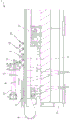
fig. 5 is an isometric view of a grinding machine according to the invention in a second embodiment;
fig. 6 is a side view of a grinding mill according to the invention in a non-operating configuration and in a second embodiment;
fig. 7 is a side view of a grinding mill according to the invention in an operating configuration and in a second embodiment;
with particular reference to these figures, a machine for grinding sheet-like elements, in particular tiles and slabs made of ceramic material, natural stone, glass, etc., is globally indicated with 1.
The machine 1 comprises a base frame 2 for resting on the ground, on the base frame 2 there being mounted advancing means 3, the advancing means 3 being intended to move at least one sheet-like element 4 on a movement plane a and along at least one advancing direction B.
The sheet element 4 is of the tile type and/or of the marble or natural stone or glass panel type.
In particular, the sheet element 4 is substantially square or rectangular and it comprises a pair of first sides 5 opposite each other and to be ground, a front side 6 and a rear side 7 opposite each other and transversal to the first sides 5.
Typically, both the front side 6 and the back side 7 have been ground.
As used herein, the expressions front and rear refer to the direction of advance of the sheet-like element 4, the front side 6 thus defining the advancing front of the sheet-like element 4.
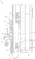
In more detail, the advancing means 3 comprise a pair of flexible elements 8, such as belts, conveyor belts or the like, which are of closed loop shape and are wound at least partially around two first advancing pulleys 9.
In particular, the flexible element 8 is movable in a direction substantially horizontal and substantially transverse to the advancement direction B.
In more detail, the advancement device 3 comprises, for each flexible element 8, an associated support element 17; the supporting elements 17 are movable along a direction horizontal and substantially transversal to the advancement direction B, approaching/moving away from each other, so as to adjust the distance between the flexible elements 8, thus varying the width of the sheet-like element 4.
The machine 1 comprises means 10 for processing the first side 5 arranged in the vicinity of the movement plane a and which are adapted to intercept (intercept) the sheet element 4 upon a movement of the sheet element 4 in the advancement direction B.
More specifically, the machining device 10 comprises a plurality of grinding and lateral bevelling wheels, preferably arranged on either side of the movement plane a and associated with the support element 17.
In the particular embodiment illustrated in the figures, the advancement device 3 has a first portion on which the sheet-like element 4 is fed and squared, and a second portion, arranged downstream of the first portion with respect to the advancement direction B, along which the sheet-like element 4 is held in a squared position.
In more detail, the advancing device 3 is moved in the advancing direction B by the first electric motor.
The machine 1 comprises square positioning means 11 for the positive positioning of the sheet-like element 4 above the movement plane a.
According to the invention, the squaring positioning means 11 comprise at least one abutment element defining at least two support points distinct from each other, suitable for contacting the front side 6 of the sheet-like element 4, so as to arrange the front side 6 in a position substantially orthogonal to the advancement direction B.
In the particular embodiment shown in the figures, the square positioning device 11 comprises a pair of abutment elements, each defining opposite support points adapted to contact the front side 6.
Preferably, each abutment element is integrally associated with the relative supporting element 17 so that it can also move in a manner approaching/moving away from each other in order to automatically adjust the width of the tab-like element 4.
The machine 1 comprises means for actuating the abutment elements, for example of the electric motor type.
The actuating means are, for example, of the brushless motor type, independent of each other, and they provide for actuating the electric shaft to move the abutment elements one with respect to the other.
In more detail, the abutment elements are movable between a non-operating position, in which they are arranged outside the trajectory in the path of the sheet-like element 4 along the advancement direction B, and an operating position, in which they are arranged along the advancement trajectory of the sheet-like element 4 so as to interfere with the sheet-like element in its path along the advancement direction B.
In the embodiment shown in the figures, the abutment elements are movable in translation along the advancement direction B with respect to the relative guide means 12, and they are also movable in a vertical direction to move from the inoperative position to the operative position and vice versa.
In the particular embodiment illustrated in the figures, the abutment element travels at least one stroke in the same advancement direction as the sheet element 4, at a speed lower than the advancement speed of the sheet element.
In more detail, moving at a lower speed than the sheet-like element 4, the abutment element comes into contact gradually with the front side 6, thus reducing the risk of breakage.
Figure 2 shows the operating state in which the abutment element is in contact with the front side 6 of the sheet element 4.
Due to the speed difference, the front side 6 contacts the two abutment elements by being positioned orthogonally to the advancing direction B.
In particular, if the front side 6 initially contacts only one of the abutment elements, it acts as a pin around which the sheet-like element 4 rotates until the front side itself also contacts the other abutment element.
During the first stroke of the abutment element, a plurality of sheet elements 4 can be fed in sequence, wherein after the front side 6 of a first sheet element 4 is squarely positioned due to its interaction with the abutment element, the front side of each subsequent first sheet element 4 rests on the rear side 7 of the sheet element preceding it, thus also in a squared position.
Advantageously, the abutment element travels after the first stroke and in the same direction at a speed higher than the advancement speed of the sheet-like element 4 and along the advancement direction B for at least one second stroke.
Figure 3 shows the abutment element spaced from the front side 6 of the sheet element 4 after the above-mentioned speed increase.
In more detail, during the second stroke, the abutment element moves away from the front side 6, allowing the sheet-like element 4 to continue in the advancing direction B.
At the end of the second stroke, the abutment element is moved to the inoperative position, as shown in fig. 4, to allow the free advancement of the sheet-like element 4 along the movement plane a.
Finally, the abutment element travels a return stroke in the opposite direction with respect to the advancing direction B of the sheet-like element 4.
In the particular embodiment shown in the figures, the advancement means 3 comprise pressing means 13, which are arranged downstream of the abutment elements with respect to the advancement direction B and are adapted to keep the sheet-like element 4 in the square position.
In particular, the distance of the pressing means 13 from the flexible element 8 can be adjusted according to the thickness of the sheet-like element 4.
In the first embodiment shown in fig. 1 to 4, the pressing means 13 comprise a pair of flexible members 14, for example belts, conveyor belts or the like, in the form of a closed loop, each of which is wound at least partially around a second actuating pulley 15.
In this first embodiment, the flexible members 14 extend longitudinally with respect to the advancement direction B, and they are arranged symmetrically with respect to a vertical plane longitudinal to the advancement direction.
In more detail, the flexible members 14 are arranged above the relative flexible elements 8 and they are adapted to press the sheet element 4 against the flexible elements.
After reaching the squaring position of the sheet element 4 and after the abutment element has moved from the operative position to the inoperative position, the sheet element 4 is inserted between the flexible element 8 and the flexible member 14.
In a second embodiment, shown in figures 5 to 7, the pressing means 13 comprise a pair of wheel units 16.
In more detail, each wheel unit 16 is arranged above the relative flexible element 8.
Similarly, with the first embodiment described above, the two wheel units 16 are arranged above the relative flexible element 8 and are symmetrical with respect to a vertical plane longitudinal to the advancement direction B.
In the two embodiments shown in the figures, the pressing means 13 are interposed between the abutment elements along a direction transverse to the advancement direction B.
In other words, the abutment element is arranged on the outside with respect to the pressing device 13 so as to intercept the sheet-like element 4 at the end of the front side 6.
The invention also relates to a method for grinding sheet elements, in particular tiles and panels made of ceramic material, natural stone, glass or the like, as described hereinafter.
Specifically, the method comprises:
a step of providing at least one sheet element 4, the at least one sheet element 4 being provided with at least one first side 5 to be ground and at least one front side 6 transversal to the first side 5;
a step of moving the sheet-like element 4 along an advancement direction B and in which the front side 6 defines the advancement front of the sheet-like element itself;
a step of squarely positioning the sheet-like element 4;
-a step of grinding the first side 5.
According to the invention, the square positioning is performed by positioning the front side 6 in a position substantially orthogonal to the advancing direction B.
In more detail, this step is carried out by bringing the front side 6 into contact with two support points substantially aligned with each other along a direction substantially orthogonal to the advancing direction B.
The feeding step may provide for a plurality of sheet-like elements 4 to be fed successively with respect to one another, each of them being provided with a rear side 7 substantially parallel and opposite to the relative front side 6.
By advancing the sheet element 4, the front side 6 of the sheet element 4 behind the first sheet element rests against the rear side 7 of the sheet element 4 arranged above with reference to the advancing direction B.
In other words, the front side of the sheet-like subsequent element 4 is arranged against the rear side 7 of the front sheet-like element 4, thereby obtaining a series of sheet-like elements 4, the sheet-like elements 4 being positioned in succession with respect to each other.
In this step of square positioning of the plurality of sheet elements 4, a grinding step is then performed on the first side 5 of each of the sheet elements 4.
Basically, it has been shown how the described invention achieves the intended aim, with particular emphasis on the machine for grinding ceramic tiles obtained in this way allowing to simplify the square positioning of the tiles with respect to machines of known type.
In particular, the square positioning by intervention on the front side not only makes it possible to simplify the structure of the machine and to reduce its overall dimensions, but also provides an alternative to the machines known hitherto.
Furthermore, the squaring positioning performed on the front side of each sheet element allows to work a plurality of tiles simultaneously, thus increasing the machine productivity, considering the same number of sheet elements to be worked to reduce the work cycle frequency or considering the same number of work cycles.
In addition, the invention allows to arrange the tiles in a square position, regardless of their width, thus guaranteeing faster operating times and reducing machine downtime for the machine setting operations performed by the operator.
Claims (10)
1. Machine (1) for grinding sheet-like elements, comprising:
-at least one base frame (2);
-advancing means (3) for advancing at least one sheet-like element (4) mounted to said base frame (2), suitable for moving said sheet-like element (4) along at least one advancing direction (B) on at least one movement plane (a), said sheet-like element (4) being provided with a pair of first sides (5) to be ground and at least one front side (6) transversal to said first sides (5) and defining an advancing front of said sheet-like element;
-means (10) for processing said first side (5), which are arranged adjacent to said movement plane (a) and which are adapted to intercept said sheet-like element (4) when said sheet-like element (4) moves along said advancement direction (B);
-square positioning means (11) for square positioning of the sheet-like element (4) on the movement plane (A),
characterized in that said square positioning device (11) comprises at least one abutment element defining at least two support points distinct from each other and adapted to come into contact with said front side (6) to arrange said front side (6) in a position substantially orthogonal to said advancing direction (B), and
the at least one abutment element is movable along the advancement direction (B).
2. Machine (1) according to claim 1, characterized in that said machine (1) comprises a pair of said abutment elements, each of which defines a relative bearing point.
3. Machine (1) according to claim 1 or 2, characterized in that said at least one abutment element is movable between a non-operative position, in which it is arranged outside the trajectory in the path of said sheet-like element (4) along said advancing direction (B); in the operating position, the at least one abutment element is arranged along an advancement trajectory of the sheet-like element (4) so as to interfere with the sheet-like element (4) in a path of the sheet-like element (4) along the advancement direction (B).
4. Machine (1) according to claim 1 or 2, characterized in that said at least one abutment element travels at least one first stroke in the same advancement direction of the sheet-like element (4) at a speed lower than the speed of the sheet-like element itself.
5. Machine (1) according to claim 4, characterized in that said at least one abutment element travels a second stroke at a higher speed than the advancement speed of said sheet-like element (4), said second stroke being subsequent to the first stroke and in the same direction.
6. Machine (1) according to claim 5, characterized in that said at least one abutment element is moved to the inoperative position at the end of the second stroke.
7. Machine (1) according to claim 1 or 2, characterized in that said at least one abutment element makes a return stroke in the opposite direction with respect to said advancing direction (B) of said sheet-like element (4).
8. Machine (1) according to claim 1 or 2, characterized in that said laminar elements are tiles and plates made of ceramic material, natural stone, glass.
9. A method for abrading a sheet-like element, comprising the steps of:
-providing at least one sheet element (4), said at least one sheet element (4) being provided with at least one first side (5) to be ground and at least one front side (6) transversal to said first side (5);
-moving the sheet-like element (4) along an advancement direction (B), the front side (6) defining an advancement front of the sheet-like element;
-squarely positioning the sheet element (4);
-grinding said first side (5);
characterized in that the square positioning is performed by positioning the front side (6) in a position substantially orthogonal to the advancing direction (B), and
-supplying for feeding a plurality of sheet-like elements (4) successively with respect to each other, each of said sheet-like elements being provided with a rear side (7) substantially parallel to the relative front side (6) and opposite to the relative front side (6), said square positioning being carried out by positioning the front side (6) of a first one of said sheet-like elements (4) in a position substantially orthogonal to the advancement direction (B), the front sides (6) of the subsequent sheet-like elements (4) resting against the rear sides (7) of the sheet-like elements (4) preceding them, said grinding being carried out on the first side (5) of each of said sheet-like elements (4).
10. Method according to claim 9, characterized in that said laminar elements are tiles and slabs made of ceramic material, natural stone, glass.
Applications Claiming Priority (3)
| Application Number | Priority Date | Filing Date | Title |
|---|---|---|---|
| IT102015000026896 | 2015-06-23 | ||
| ITUB20151603 | 2015-06-23 | ||
| PCT/IB2016/053715 WO2016207814A1 (en) | 2015-06-23 | 2016-06-22 | Grinding machine for plate-like elements, particularly ceramic tiles and plates, natural stones, glass or similar |
Publications (2)
| Publication Number | Publication Date |
|---|---|
| CN107921600A CN107921600A (en) | 2018-04-17 |
| CN107921600B true CN107921600B (en) | 2020-01-10 |
Family
ID=54199987
Family Applications (1)
| Application Number | Title | Priority Date | Filing Date |
|---|---|---|---|
| CN201680040615.4A Expired - Fee Related CN107921600B (en) | 2015-06-23 | 2016-06-22 | Grinding machine for plate-like elements, in particular tiles and slabs, natural stone, glass or the like |
Country Status (7)
| Country | Link |
|---|---|
| US (1) | US10654143B2 (en) |
| EP (1) | EP3313612B1 (en) |
| CN (1) | CN107921600B (en) |
| BR (1) | BR112017027399B1 (en) |
| ES (1) | ES2758729T3 (en) |
| PL (1) | PL3313612T3 (en) |
| WO (1) | WO2016207814A1 (en) |
Families Citing this family (6)
| Publication number | Priority date | Publication date | Assignee | Title |
|---|---|---|---|---|
| JP6427615B2 (en) * | 2017-04-12 | 2018-11-21 | 株式会社アマダホールディングス | Work placement table device |
| CN107116415A (en) * | 2017-05-04 | 2017-09-01 | 佛山市顺德区力创鑫玻璃机械有限公司 | A kind of high speed folding running-in machine |
| IT201800006453A1 (en) * | 2018-06-19 | 2019-12-19 | Plate grinding machine | |
| IT201800006792A1 (en) * | 2018-06-28 | 2019-12-28 | SYSTEM FOR ADJUSTING THE PRESSURE OF THE SHEET RETENTION SYSTEMS DURING SQUARING PHASE | |
| CN110202644B (en) * | 2019-06-24 | 2021-09-14 | 郑微丹 | Positioning type sawing device |
| CN112388455B (en) * | 2021-01-21 | 2021-06-29 | 机械科学研究总院江苏分院有限公司 | Polishing module and polishing device |
Citations (5)
| Publication number | Priority date | Publication date | Assignee | Title |
|---|---|---|---|---|
| EP0504442A1 (en) * | 1991-03-18 | 1992-09-23 | Homag Maschinenbau Ag | Device for feeding workpieces to a production machine |
| CN1278472A (en) * | 1999-06-21 | 2001-01-03 | Z·巴维罗尼股份公司 | Double-edge automatic processing machine for processing edges of glass or stone plate materials |
| EP1649976A1 (en) * | 2004-10-19 | 2006-04-26 | BIESSE S.p.A. | Machine for working the edges of glass, marble, stone or ceramic materials and the like |
| CN203696659U (en) * | 2013-12-07 | 2014-07-09 | 重庆嘉威特节能玻璃有限公司 | Intelligent bilateral edge grinding machine |
| EP2544858B1 (en) * | 2010-03-08 | 2014-09-24 | Tecnema Technology S.r.l. | Machine for grinding plate-shaped elements, particularly tiles and slab of ceramic material, natural stones, glass or the like |
Family Cites Families (9)
| Publication number | Priority date | Publication date | Assignee | Title |
|---|---|---|---|---|
| US1797342A (en) * | 1924-12-23 | 1931-03-24 | Marietta Mfg Co | Edging machine |
| US2170687A (en) * | 1938-05-16 | 1939-08-22 | Arthur B Johnson | Tiltable cutter unit |
| US3805455A (en) * | 1972-12-04 | 1974-04-23 | Glassline Corp | Apparatus for grinding parallel edges of glass sheets |
| JPS5443780U (en) * | 1977-09-02 | 1979-03-26 | ||
| US4228617A (en) * | 1977-12-31 | 1980-10-21 | Bando Kiko Co., Ltd | Method for grinding glass plates and the like through numerical control and beveling machine therefor |
| SU783002A1 (en) | 1978-11-27 | 1980-11-30 | за витель 54) УСТРОЙСТВО ДЛЯ ОТМЕРА ДЛИН СОРТИМЕНТОВ О. С. Матвеев | Device for measuring-out sawn timber lengths |
| IT1320224B1 (en) * | 2000-06-30 | 2003-11-26 | Forvet S R L | METHOD AND GRINDING MACHINE FOR THE PROCESSING OF GLASS SHEETS. |
| ITBO20020074A1 (en) | 2002-02-15 | 2003-08-18 | Biesse Spa | MACHINE FOR THE PROCESSING OF WOOD PANELS OR SIMILAR |
| US7001249B1 (en) * | 2005-01-11 | 2006-02-21 | Guardian Industries, Inc. | Methods and systems for finishing edges of glass sheets |
-
2016
- 2016-06-22 EP EP16751639.2A patent/EP3313612B1/en active Active
- 2016-06-22 BR BR112017027399-3A patent/BR112017027399B1/en active IP Right Grant
- 2016-06-22 ES ES16751639T patent/ES2758729T3/en active Active
- 2016-06-22 CN CN201680040615.4A patent/CN107921600B/en not_active Expired - Fee Related
- 2016-06-22 PL PL16751639T patent/PL3313612T3/en unknown
- 2016-06-22 US US15/738,277 patent/US10654143B2/en active Active
- 2016-06-22 WO PCT/IB2016/053715 patent/WO2016207814A1/en active Application Filing
Patent Citations (5)
| Publication number | Priority date | Publication date | Assignee | Title |
|---|---|---|---|---|
| EP0504442A1 (en) * | 1991-03-18 | 1992-09-23 | Homag Maschinenbau Ag | Device for feeding workpieces to a production machine |
| CN1278472A (en) * | 1999-06-21 | 2001-01-03 | Z·巴维罗尼股份公司 | Double-edge automatic processing machine for processing edges of glass or stone plate materials |
| EP1649976A1 (en) * | 2004-10-19 | 2006-04-26 | BIESSE S.p.A. | Machine for working the edges of glass, marble, stone or ceramic materials and the like |
| EP2544858B1 (en) * | 2010-03-08 | 2014-09-24 | Tecnema Technology S.r.l. | Machine for grinding plate-shaped elements, particularly tiles and slab of ceramic material, natural stones, glass or the like |
| CN203696659U (en) * | 2013-12-07 | 2014-07-09 | 重庆嘉威特节能玻璃有限公司 | Intelligent bilateral edge grinding machine |
Also Published As
| Publication number | Publication date |
|---|---|
| US10654143B2 (en) | 2020-05-19 |
| PL3313612T3 (en) | 2020-06-29 |
| EP3313612B1 (en) | 2019-09-04 |
| BR112017027399A2 (en) | 2018-08-21 |
| EP3313612A1 (en) | 2018-05-02 |
| WO2016207814A1 (en) | 2016-12-29 |
| ES2758729T3 (en) | 2020-05-06 |
| BR112017027399B1 (en) | 2022-08-09 |
| CN107921600A (en) | 2018-04-17 |
| US20180193969A1 (en) | 2018-07-12 |
Similar Documents
| Publication | Publication Date | Title |
|---|---|---|
| CN107921600B (en) | Grinding machine for plate-like elements, in particular tiles and slabs, natural stone, glass or the like | |
| CN104511944B (en) | Rotary clicker press machine | |
| EP2544858B1 (en) | Machine for grinding plate-shaped elements, particularly tiles and slab of ceramic material, natural stones, glass or the like | |
| KR101564217B1 (en) | Milling apparatus | |
| EP2845840B1 (en) | Machine and method for performing cutting operations on laminated-glass plates | |
| EP1770031B1 (en) | Assembly for conveying sheets on machines for working sheets, particularly glass sheets and the like | |
| CN105345130A (en) | Efficient profile shearing device with precise guiding function | |
| CN105414657A (en) | Machining device for stably shearing sections in size-positioning manner | |
| CN103921163A (en) | Directional processing device for stepped cylindrical workpieces | |
| KR100609075B1 (en) | Apparatus for machining four surfaces of metal rods | |
| CN105537662A (en) | Fixed-size precise shear method of home decoration profiles | |
| WO2012130737A1 (en) | Cutting and working machine particularly for ceramic material, stone-like material and the like | |
| CN105397178A (en) | Section bar processing device stable and accurate in shearing | |
| KR20150075278A (en) | Apparatus for arraying materials | |
| CA2687357C (en) | Transport device for a finger jointing system | |
| CN210188098U (en) | Feeding mechanism for machining cutting die | |
| CN105328501A (en) | Section bar guide device for improving use efficiency of machine tool | |
| CN105436603A (en) | Sectional material cutting device with locating material stop function | |
| WO2021099918A1 (en) | Device for detecting the orientation of an edge of a slab-shaped element and machine comprising said detection device | |
| JP2020146858A (en) | Double end tenoner | |
| NO328081B1 (en) | Machine and method for providing joints in boards and / or for cutting tiles from boards | |
| CN105537672A (en) | Precise and rapid shear process of building profile | |
| CN103639516B (en) | A kind of board notch automatic machining device | |
| CN110102600B (en) | Feeding mechanism for machining cutting die | |
| JP6544493B2 (en) | Glass plate breaking machine |
Legal Events
| Date | Code | Title | Description |
|---|---|---|---|
| PB01 | Publication | ||
| PB01 | Publication | ||
| SE01 | Entry into force of request for substantive examination | ||
| SE01 | Entry into force of request for substantive examination | ||
| GR01 | Patent grant | ||
| GR01 | Patent grant | ||
| CF01 | Termination of patent right due to non-payment of annual fee |
Granted publication date: 20200110 Termination date: 20210622 |
|
| CF01 | Termination of patent right due to non-payment of annual fee |