EP1770031B1 - Assembly for conveying sheets on machines for working sheets, particularly glass sheets and the like - Google Patents
Assembly for conveying sheets on machines for working sheets, particularly glass sheets and the like Download PDFInfo
- Publication number
- EP1770031B1 EP1770031B1 EP20060020102 EP06020102A EP1770031B1 EP 1770031 B1 EP1770031 B1 EP 1770031B1 EP 20060020102 EP20060020102 EP 20060020102 EP 06020102 A EP06020102 A EP 06020102A EP 1770031 B1 EP1770031 B1 EP 1770031B1
- Authority
- EP
- European Patent Office
- Prior art keywords
- sheet
- belts
- sheets
- assembly
- belt
- Prior art date
- Legal status (The legal status is an assumption and is not a legal conclusion. Google has not performed a legal analysis and makes no representation as to the accuracy of the status listed.)
- Not-in-force
Links
- 239000011521 glass Substances 0.000 title claims abstract description 19
- 238000011144 upstream manufacturing Methods 0.000 claims abstract description 5
- 239000002344 surface layer Substances 0.000 claims description 2
- 230000000712 assembly Effects 0.000 description 6
- 238000000429 assembly Methods 0.000 description 6
- 230000000717 retained effect Effects 0.000 description 4
- 239000011248 coating agent Substances 0.000 description 1
- 238000000576 coating method Methods 0.000 description 1
- 230000002860 competitive effect Effects 0.000 description 1
- 238000003780 insertion Methods 0.000 description 1
- 230000037431 insertion Effects 0.000 description 1
- 230000014759 maintenance of location Effects 0.000 description 1
- 239000000463 material Substances 0.000 description 1
- 238000000034 method Methods 0.000 description 1
- 238000004381 surface treatment Methods 0.000 description 1
- 230000003245 working effect Effects 0.000 description 1
Images


Classifications
-
- B—PERFORMING OPERATIONS; TRANSPORTING
- B65—CONVEYING; PACKING; STORING; HANDLING THIN OR FILAMENTARY MATERIAL
- B65G—TRANSPORT OR STORAGE DEVICES, e.g. CONVEYORS FOR LOADING OR TIPPING, SHOP CONVEYOR SYSTEMS OR PNEUMATIC TUBE CONVEYORS
- B65G49/00—Conveying systems characterised by their application for specified purposes not otherwise provided for
- B65G49/05—Conveying systems characterised by their application for specified purposes not otherwise provided for for fragile or damageable materials or articles
- B65G49/06—Conveying systems characterised by their application for specified purposes not otherwise provided for for fragile or damageable materials or articles for fragile sheets, e.g. glass
- B65G49/063—Transporting devices for sheet glass
- B65G49/064—Transporting devices for sheet glass in a horizontal position
-
- C—CHEMISTRY; METALLURGY
- C03—GLASS; MINERAL OR SLAG WOOL
- C03B—MANUFACTURE, SHAPING, OR SUPPLEMENTARY PROCESSES
- C03B33/00—Severing cooled glass
- C03B33/02—Cutting or splitting sheet glass or ribbons; Apparatus or machines therefor
- C03B33/023—Cutting or splitting sheet glass or ribbons; Apparatus or machines therefor the sheet or ribbon being in a horizontal position
- C03B33/03—Glass cutting tables; Apparatus for transporting or handling sheet glass during the cutting or breaking operations
-
- Y—GENERAL TAGGING OF NEW TECHNOLOGICAL DEVELOPMENTS; GENERAL TAGGING OF CROSS-SECTIONAL TECHNOLOGIES SPANNING OVER SEVERAL SECTIONS OF THE IPC; TECHNICAL SUBJECTS COVERED BY FORMER USPC CROSS-REFERENCE ART COLLECTIONS [XRACs] AND DIGESTS
- Y10—TECHNICAL SUBJECTS COVERED BY FORMER USPC
- Y10T—TECHNICAL SUBJECTS COVERED BY FORMER US CLASSIFICATION
- Y10T83/00—Cutting
- Y10T83/444—Tool engages work during dwell of intermittent workfeed
- Y10T83/4604—Work feed functions as tool support
-
- Y—GENERAL TAGGING OF NEW TECHNOLOGICAL DEVELOPMENTS; GENERAL TAGGING OF CROSS-SECTIONAL TECHNOLOGIES SPANNING OVER SEVERAL SECTIONS OF THE IPC; TECHNICAL SUBJECTS COVERED BY FORMER USPC CROSS-REFERENCE ART COLLECTIONS [XRACs] AND DIGESTS
- Y10—TECHNICAL SUBJECTS COVERED BY FORMER USPC
- Y10T—TECHNICAL SUBJECTS COVERED BY FORMER US CLASSIFICATION
- Y10T83/00—Cutting
- Y10T83/444—Tool engages work during dwell of intermittent workfeed
- Y10T83/461—With abutment to position work being fed with respect to cutter
-
- Y—GENERAL TAGGING OF NEW TECHNOLOGICAL DEVELOPMENTS; GENERAL TAGGING OF CROSS-SECTIONAL TECHNOLOGIES SPANNING OVER SEVERAL SECTIONS OF THE IPC; TECHNICAL SUBJECTS COVERED BY FORMER USPC CROSS-REFERENCE ART COLLECTIONS [XRACs] AND DIGESTS
- Y10—TECHNICAL SUBJECTS COVERED BY FORMER USPC
- Y10T—TECHNICAL SUBJECTS COVERED BY FORMER US CLASSIFICATION
- Y10T83/00—Cutting
- Y10T83/444—Tool engages work during dwell of intermittent workfeed
- Y10T83/463—Work-feed element contacts and moves with work
-
- Y—GENERAL TAGGING OF NEW TECHNOLOGICAL DEVELOPMENTS; GENERAL TAGGING OF CROSS-SECTIONAL TECHNOLOGIES SPANNING OVER SEVERAL SECTIONS OF THE IPC; TECHNICAL SUBJECTS COVERED BY FORMER USPC CROSS-REFERENCE ART COLLECTIONS [XRACs] AND DIGESTS
- Y10—TECHNICAL SUBJECTS COVERED BY FORMER USPC
- Y10T—TECHNICAL SUBJECTS COVERED BY FORMER US CLASSIFICATION
- Y10T83/00—Cutting
- Y10T83/444—Tool engages work during dwell of intermittent workfeed
- Y10T83/4637—With means to guide, position, or present work to work-feed means
- Y10T83/464—Means to transport work to work-feed means
Definitions
- the present invention relates to an assembly for conveying sheets on machines for working sheets, particularly glass sheets and the like.
- the conveyance assembly is provided with presser rollers or belts, which engage the surface of the sheet and retain it during work; these means very often cause damage to the surface of the sheet, especially when working on glass sheets with a "LOW-E" type coating.
- One of such sides is typically fixed, while the other pair of belts can perform a translational motion so as to adapt easily to the width of the sheet.
- Each pair of belts is formed by a belt which is fixed on the supporting surface and engages the lower side of the sheet, while the other belt can move vertically in order to engage the upper side so as to apply an adequate pressure which ensures the retention of the sheet during work.
- Another problem consists further in that it is not always possible to retain the sheet firmly, and therefore work imperfections and vibrations can occur which damage the tools and produce lower-quality work.
- JP-2004026569 discloses an apparatus for performing scribing, breaking or chamfering of a glass plate by repeating a sending action of the glass plate and a working action for fixing the glass plate and working the glass plate in the sending direction or the direction orthogonally crossing the sending direction.
- US-2004/0237737 discloses a process and device for moving and positioning sheets of glass.
- the aim of the invention is to solve the problems described above by providing an assembly for conveying sheets on machines for working sheets, particularly glass sheets and the like, which allows to work both along the edges of the sheet and on the surface of the sheet, with the additional possibility to move the working heads so that they work in both directions of advancement of the sheet.
- an object of the invention is to provide a conveyance assembly which does not produce surface damage of the sheets, which are always retained perfectly, so that all work can be performed in an optimum manner.
- Another object of the present invention is to provide a conveyance assembly which, thanks to its particular constructive characteristics, is capable of giving the greatest assurances of reliability and safety in use.
- Still another object of the present invention is to provide an assembly for conveying sheets on machines for working sheets, particularly glass sheets and the like, which can be obtained easily starting from commonly commercially available elements and materials and is further competitive from a merely economical standpoint.
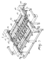
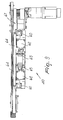
- the assembly for conveying sheets on machines for working sheets, particularly glass sheets, generally designated by the reference numeral 1 comprises a sheet feeder assembly 2 and a sheet removal assembly 3, which are arranged respectively upstream and downstream of a working machine 4 which is interposed between the two removal assemblies.
- a sheet insertion assembly designated by the reference numeral 6, which is provided by means of a conventional roller bed, and an output assembly, constituted by a roller bed 7 arranged at the output of the removal assembly.
- a particular feature of the invention consists in that the sheet feeder assembly that engages the longitudinal edges of the sheets, where "longitudinal” refers to the direction of advancement of the sheets, is constitute by means of a supporting frame 10, which supports the elements that constitute the assembly, which is constituted by a pair of mutually opposite fixed-position belts 11, and a pair of mutually opposite variable-position belts 12, which can perform a translational motion toward and away from the pair of fixed-position belts in order to adapt to the width of the sheet.
- the pairs of belts 11 and 12 are constituted respectively by a lower fixed-position feeder belt 13, which is actuated by a first motor 14, which moves the belt.
- a controlled feeder belt 15 with adjustable position is positioned above the belt 13 and can perform a translational motion along a direction which is perpendicular to the plane of arrangement of the sheet, designated by the reference letter L, so as to adapt to the thickness of the sheet.
- the belt 15 is actuated with positioning means which will be described hereinafter.
- variable-position belts 12 are provided with a lower, fixed-position, feeder belt 20, which lies below the sheet and is connected to and actuated by a second motor 21.
- An adjustable upper feeder belt 22 is arranged above the belt 20, which can perform a translational motion on a direction perpendicular to the sheet arrangement plane, and can also be motorized or free.
- the feeder assembly is completed by a transverse feeder roller 30, which engages the lower face of the sheet and in practice supports it along a transverse direction, i.e., at right angles to the extension of the longitudinal edges.
- central rollers 32 which are designed to support large sheets and are arranged halfway along the width of the sheet.
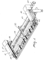
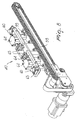
- the removal assembly 3 is constituted by a pair of fixed-position removal belts 40, opposite to which there is a pair of variable-position removal belts 41, which like the pair of belts 12 can perform a translational motion in order to adapt to the different widths of the sheet.
- the pairs of belts 40 and 41 in a manner similar to the pairs 11 and 12, are provided by means of a lower fixed-position removal belt 42, above which there is an adjustable upper removal belt 43.
- the belt 42 is connected to a third motor 44, while the belt 43 in this case also can be motorized or free.
- the pair of belts 41 is provided with a lower variable or movable-position belt 46, which is connected to a fourth motor 47, above which an adjustable removal belt 48 is arranged that can perform a translational motion along a direction perpendicular to the sheet arrangement plane.
- the assembly is completed by a transverse roller 49, which engages along the transverse direction of the sheet, and a removal assembly formed of a series of central removal rollers 50, which support large sheets.
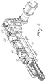
- Each pair of belts 11, 12, 40 and 41 is arranged at rollers abutment 55 which have a vertical axis and are designed to act as an abutment and positioning element by engaging the edge of the sheet.
- each pair of belts has a parallelogram mechanism 60, which supports the entire belt positioning means 61, on which a vertical actuation cylinder 62 is connected which makes the upper belts 15, 22, 43, 48 press against the upper surface of the glass sheet at the set pressure.
- a block 63 is actuated and acts on the stem of a cylinder 62, such block 63 constituting belt locking means for locking in position the adjustable belts.
- the upper belts have a covering provided by surface treatment which prevents damage of the surface layers sometimes provided on the upper face of the glass sheet.
- the working machine 4 is interposed advantageously between the feeder assembly and the removal assembly and supports one or more working heads; designated by the reference numeral 70, which can move along the transverse direction and can perform a translational motion at right angles to the plane of arrangement of the sheet.
- the sheet is always retained perfectly in close proximity to the work area, thanks to the fact that the belts always engage the longitudinal edges of the sheet and there is also a roller which is positioned on the transverse edge and retains the sheet.
- the sheet L to be worked is guided by means of the roller bed 6 which is located upstream of the feeder assembly and the sheet is already positioned with its longitudinal edges parallel to the advancement line and with its transverse edges at right angles.
- One of the longitudinal edges is already positioned on the reference constituted by the rollers having a vertical axis.
- the pairs of variable-positioning belts are positioned as a function of the size of the sheet, which is set by a numeric control, and when the sheet engages the pairs of belts along their length the movable pairs perform an additional stroke, which allows to generate a lateral pressure between the sheet L and the rollers 55 having a vertical axis, in order to ensure correct alignment of the sheet against the references.
- the upper belts descend at the preset pressure, until the closure position is reached, as indicated by a pressure switch; the block 63 is activated and locks the upper structure, which can move at right angles to the plane of arrangement of the sheet.
- the upper belts of the removal assembly descend at the preset pressure, and when the closure position indicated by a pressure switch is reached, the locking systems are activated as in the preceding case.
- the invention achieves the proposed aim and objects, and in particular the fact is stressed that the use of two separate conveyance assemblies, i.e., the feeder assembly and the removal assembly, allows to work on any point of the sheet, since the working heads are in practice independent of the structure that provides the movement of the sheet and can move transversely and vertically.
- the removal assembly moves away the sheet on the downstream roller bed.
- the feeder and removal assemblies can move synchronously, typically during working, or at different speeds in order to move away a finished part and simultaneously set up a new part in input.
- the pneumatic movement system for the upper belts avoids the need to check their position as a function of the thickness of the glass sheet.
Abstract
Description
- The present invention relates to an assembly for conveying sheets on machines for working sheets, particularly glass sheets and the like.
- As is known, glass sheets and the like are currently worked by using conveyance assemblies designed to feed the sheet below the working heads, which perform the required work.
- According to the background art, the conveyance assembly is provided with presser rollers or belts, which engage the surface of the sheet and retain it during work; these means very often cause damage to the surface of the sheet, especially when working on glass sheets with a "LOW-E" type coating.
- In order to try to solve this problem, solutions have already been introduced in which the conveyance assembly is provided by means of two pairs of belts arranged on opposite sides along the sheet advancement direction and retain the sheet only upstream of the work area.
- One of such sides is typically fixed, while the other pair of belts can perform a translational motion so as to adapt easily to the width of the sheet.
- Each pair of belts is formed by a belt which is fixed on the supporting surface and engages the lower side of the sheet, while the other belt can move vertically in order to engage the upper side so as to apply an adequate pressure which ensures the retention of the sheet during work.
- With this type of conveyance assembly, it is possible to perform work only along the sides affected by the belts and with a single direction of advancement.
- Another problem consists further in that it is not always possible to retain the sheet firmly, and therefore work imperfections and vibrations can occur which damage the tools and produce lower-quality work.
-
JP-2004026569 -
US-2004/0232188 discloses an apparatus as defined in the preamble of claim 1. -
US-2004/0237737 discloses a process and device for moving and positioning sheets of glass. - The aim of the invention is to solve the problems described above by providing an assembly for conveying sheets on machines for working sheets, particularly glass sheets and the like, which allows to work both along the edges of the sheet and on the surface of the sheet, with the additional possibility to move the working heads so that they work in both directions of advancement of the sheet.
- Within this aim, an object of the invention is to provide a conveyance assembly which does not produce surface damage of the sheets, which are always retained perfectly, so that all work can be performed in an optimum manner.
- Another object of the present invention is to provide a conveyance assembly which, thanks to its particular constructive characteristics, is capable of giving the greatest assurances of reliability and safety in use.
- Still another object of the present invention is to provide an assembly for conveying sheets on machines for working sheets, particularly glass sheets and the like, which can be obtained easily starting from commonly commercially available elements and materials and is further competitive from a merely economical standpoint.
- This aim and these and other objects, which will become better apparent hereinafter, are achieved by an assembly for conveying sheets on machines for working sheets, particularly glass sheets and the like, as defined in claim 1.
- Further characteristics and advantages will become better apparent from the description of a preferred but not exclusive embodiment of an assembly for conveying sheets on machines for working sheets, particularly glass sheets and the like, illustrated by way of non-limiting example in the accompanying drawings, wherein:
-
Figure 1 is a schematic perspective view of the conveyance assembly according to the invention, applied to a machine for working the sheet; -
Figure 2 is a schematic view of the conveyance assembly positioned with respect to the working head; -
Figure 3 is a schematic perspective view of the conveyance assembly with the working head removed; -
Figure 4 is a schematic view of the sheet removal assembly; -
Figure 5 is a view of a detail of the transverse conveyance element; -
Figure 6 is a perspective view of the fixed part of the removal assembly, taken from one side; -
Figure 7 is a view of the fixed part of the removal assembly, taken from the other side; -
Figure 8 is a view of a removal assembly, with the upper belt removed; -
Figure 9 is a plan view of a removal assembly. - With reference to the Figures, the assembly for conveying sheets on machines for working sheets, particularly glass sheets, generally designated by the reference numeral 1, comprises a sheet feeder assembly 2 and a
sheet removal assembly 3, which are arranged respectively upstream and downstream of aworking machine 4 which is interposed between the two removal assemblies. - In greater detail, there are also a sheet insertion assembly, designated by the
reference numeral 6, which is provided by means of a conventional roller bed, and an output assembly, constituted by aroller bed 7 arranged at the output of the removal assembly. - A particular feature of the invention consists in that the sheet feeder assembly that engages the longitudinal edges of the sheets, where "longitudinal" refers to the direction of advancement of the sheets, is constitute by means of a supporting
frame 10, which supports the elements that constitute the assembly, which is constituted by a pair of mutually opposite fixed-position belts 11, and a pair of mutually opposite variable-position belts 12, which can perform a translational motion toward and away from the pair of fixed-position belts in order to adapt to the width of the sheet. - The pairs of
belts 11 and 12 are constituted respectively by a lower fixed-position feeder belt 13, which is actuated by a first motor 14, which moves the belt. - A controlled
feeder belt 15 with adjustable position is positioned above thebelt 13 and can perform a translational motion along a direction which is perpendicular to the plane of arrangement of the sheet, designated by the reference letter L, so as to adapt to the thickness of the sheet. - The
belt 15 is actuated with positioning means which will be described hereinafter. - The variable-
position belts 12 are provided with a lower, fixed-position,feeder belt 20, which lies below the sheet and is connected to and actuated by asecond motor 21. - An adjustable
upper feeder belt 22 is arranged above thebelt 20, which can perform a translational motion on a direction perpendicular to the sheet arrangement plane, and can also be motorized or free. - The feeder assembly is completed by a
transverse feeder roller 30, which engages the lower face of the sheet and in practice supports it along a transverse direction, i.e., at right angles to the extension of the longitudinal edges. - In this manner, the sheet is retained correctly in order to be fed below the
working machine 4. - There is also a plurality of
central rollers 32, which are designed to support large sheets and are arranged halfway along the width of the sheet. - Likewise, the
removal assembly 3 is constituted by a pair of fixed-position removal belts 40, opposite to which there is a pair of variable-position removal belts 41, which like the pair ofbelts 12 can perform a translational motion in order to adapt to the different widths of the sheet. - The pairs of
belts pairs 11 and 12, are provided by means of a lower fixed-position removal belt 42, above which there is an adjustableupper removal belt 43. Thebelt 42 is connected to athird motor 44, while thebelt 43 in this case also can be motorized or free. - Likewise, the pair of
belts 41 is provided with a lower variable or movable-position belt 46, which is connected to afourth motor 47, above which anadjustable removal belt 48 is arranged that can perform a translational motion along a direction perpendicular to the sheet arrangement plane. - The assembly is completed by a
transverse roller 49, which engages along the transverse direction of the sheet, and a removal assembly formed of a series ofcentral removal rollers 50, which support large sheets. - Each pair of
belts rollers abutment 55 which have a vertical axis and are designed to act as an abutment and positioning element by engaging the edge of the sheet. - In order to adjust the position of the upper, adjustable belts, each pair of belts has a
parallelogram mechanism 60, which supports the entire belt positioning means 61, on which avertical actuation cylinder 62 is connected which makes theupper belts - Once the belt has reached the intended position, a
block 63 is actuated and acts on the stem of acylinder 62,such block 63 constituting belt locking means for locking in position the adjustable belts. - It should also be added to the above that the upper belts have a covering provided by surface treatment which prevents damage of the surface layers sometimes provided on the upper face of the glass sheet.
- With the arrangement described above, the
working machine 4 is interposed advantageously between the feeder assembly and the removal assembly and supports one or more working heads; designated by thereference numeral 70, which can move along the transverse direction and can perform a translational motion at right angles to the plane of arrangement of the sheet. - With this arrangement it is therefore possible to work both on the longitudinal edges of the sheet and on its transverse edges, as well as on the upper surface of the sheet, since the sheet is always retained and moved perfectly and the positioning of the belts is independent of the positioning of the working heads, which are supported by the bridge frame, designated by the reference numeral 4a, which is interposed between the feeder assembly and the removal assembly which form the sheet conveyance assembly.
- With the arrangement described above, the sheet is always retained perfectly in close proximity to the work area, thanks to the fact that the belts always engage the longitudinal edges of the sheet and there is also a roller which is positioned on the transverse edge and retains the sheet.
- In practical operation, the sheet L to be worked is guided by means of the
roller bed 6 which is located upstream of the feeder assembly and the sheet is already positioned with its longitudinal edges parallel to the advancement line and with its transverse edges at right angles. - One of the longitudinal edges is already positioned on the reference constituted by the rollers having a vertical axis.
- Before the sheet engages the feeder assembly, the pairs of variable-positioning belts are positioned as a function of the size of the sheet, which is set by a numeric control, and when the sheet engages the pairs of belts along their length the movable pairs perform an additional stroke, which allows to generate a lateral pressure between the sheet L and the
rollers 55 having a vertical axis, in order to ensure correct alignment of the sheet against the references. - Once the pairs of belts have been positioned according to the width of the sheet, the upper belts descend at the preset pressure, until the closure position is reached, as indicated by a pressure switch; the
block 63 is activated and locks the upper structure, which can move at right angles to the plane of arrangement of the sheet. - Once the sheet has been locked between the upper and lower belts, such sheet is moved in the longitudinal direction in order to detect the transverse input edge by means of an electromechanical sensor.
- Work then begins in which the assemblies or pairs of motorized belts allow the longitudinal movement of the sheet in the two directions of advancement, while the working heads move along the transverse direction and along the vertical direction, allowing any type of work.
- When, during working, the sheet engages the removal assembly for a set length, the upper belts of the removal assembly descend at the preset pressure, and when the closure position indicated by a pressure switch is reached, the locking systems are activated as in the preceding case.
- From what has been described above it is therefore evident that the invention achieves the proposed aim and objects, and in particular the fact is stressed that the use of two separate conveyance assemblies, i.e., the feeder assembly and the removal assembly, allows to work on any point of the sheet, since the working heads are in practice independent of the structure that provides the movement of the sheet and can move transversely and vertically.
- When the working of the sheet has ended, the removal assembly moves away the sheet on the downstream roller bed.
- The feeder and removal assemblies can move synchronously, typically during working, or at different speeds in order to move away a finished part and simultaneously set up a new part in input.
- If the next sheet has the same thickness, the upper belts of both assemblies remain in position, thus reducing operating times.
- The pneumatic movement system for the upper belts avoids the need to check their position as a function of the thickness of the glass sheet.
Claims (13)
- An assembly for conveying sheets on machines (4) for working sheets, particularly glass sheets and the like, comprising an assembly (2) for feeding the sheets to be worked, which engages the longitudinal edges of the sheets and is arranged upstream of a frame (4a) for supporting at least one working head (70), and an assembly (3) for removing the sheets, which engages the longitudinal edges of the sheets and is arranged downstream of said frame (4a) for supporting a working head (70), characterized in that said sheet feeder assembly (2) and said sheet removal assembly (3) are:- each provided by a pair of mutually opposite fixed position belts (11, 40) and by a pair of mutually opposite variable-position belts (12, 41),- said variable-position belts (12, 41) being variable in position in order to adapt to width of the sheet,- said pairs of belts being provided for each longitudinal edge of the sheet (L) and being constituted of a lower fixed belt (13, 20, 42, 46) and of an upper belt (15, 22, 43, 48), said upper belt being variable in position in order to adapt to the width of the sheet.
- The conveyance assembly according to claim 1, characterized in that said pair of fixed-position belts (11) have a lower fixed-position feeder belt (13) actuated by a first motor (14), a belt (15) whose position can be adjusted along a direction which is perpendicular to the plane of arrangement of said sheet (L) being positioned above said lower fixed-position feeder belt (13).
- The conveyance assembly according to claim 1, characterized in that said pair of variable position feeder belts (12) is provided with a lower fixed-position feeder belt (20), which is actuated by a second motor (21) and above which there is an adjustable-position belt (22), which can perform a translational motion along a direction which is perpendicular to the plane of arrangement of the sheet (L).
- The conveyance assembly according to claim 1, characterized in that said pair of fixed-position removal belts (40) comprises a lower fixed-position removal belt (42), above which there is an adjustable removal belt (43), which can perform a translational motion along a direction at right angles to the plane of arrangement of the sheet (L).
- The conveyance assembly according to claim 1, characterized in that said pair of variable-position removal belts (41) comprises a lower movable-position removal belt (46), which is actuated by a fourth motor (47) above which there is an adjustable removal belt (48), which can perform a translational motion along a direction which is perpendicular to the plane of arrangement of the sheet (L).
- The conveyance assembly according to one or more of the preceding claims, characterized in that it comprises, for said feeder assembly (2) and for said removal assembly (3), a transverse roller (49)which engages the lower face of the sheet (L) along a transverse direction at right angles to said longitudinal direction.
- The conveyance assembly according to one or more of the preceding claims, characterized in that it comprises, for said feeder assembly (2) and for said removal assembly (3), a series of central rollers (50), which can be positioned in a central portion of the width of the sheet (L) being worked.
- The conveyance assembly according to claim 1, characterized in that rollers (55) having a vertical axis are positioned at each pair of belts and are adapted to act as an abutment and positioning element by engaging the edge of the sheet (L) being worked.
- The conveyance assembly according to claim 5, characterized in that it comprises positioning means (61) for said adjustable belts (15, 22, 43,48), said positioning means being provided with a support for the frame of the corresponding belt, actuation cylinders (62) being positioned on said frame and being adapted to make the adjustable belts (15, 22, 43,48) press against the surface of the sheet (L) being worked.
- The conveyance assembly according to claim 5, characterized in that it comprises means (63) for locking said adjustable belts in position.
- The conveyance assembly according to claim 5, characterized in that said upper belts (15,22,43,48) have a covering adapted to prevent damage of the surface layers of the sheet (L) being worked.
- The conveyance assembly according to one or more of the preceding claims, characterized in that it forms a free space between said feeder assembly (2) and said removal assembly (3) in order to position said frame (4a) for supporting at least one working head (70).
- The conveyance assembly according to one or more of the preceding claims, characterized in that said assembly for conveying at least one working head comprises a bridge-like frame (4a), which supports at least one working head (70) which can perform a translational motion along a transverse direction.
Applications Claiming Priority (1)
| Application Number | Priority Date | Filing Date | Title |
|---|---|---|---|
| ITMI20051851 ITMI20051851A1 (en) | 2005-09-30 | 2005-09-30 | TRANSPORT GROUP FOR SLABS ON SLABS MACHINES IN PARTICULAR GLASS SHEETS AND SIMILAR |
Publications (2)
| Publication Number | Publication Date |
|---|---|
| EP1770031A1 EP1770031A1 (en) | 2007-04-04 |
| EP1770031B1 true EP1770031B1 (en) | 2010-03-03 |
Family
ID=37491735
Family Applications (1)
| Application Number | Title | Priority Date | Filing Date |
|---|---|---|---|
| EP20060020102 Not-in-force EP1770031B1 (en) | 2005-09-30 | 2006-09-26 | Assembly for conveying sheets on machines for working sheets, particularly glass sheets and the like |
Country Status (5)
| Country | Link |
|---|---|
| US (1) | US7571801B2 (en) |
| EP (1) | EP1770031B1 (en) |
| AT (1) | ATE459561T1 (en) |
| DE (1) | DE602006012592D1 (en) |
| IT (1) | ITMI20051851A1 (en) |
Families Citing this family (8)
| Publication number | Priority date | Publication date | Assignee | Title |
|---|---|---|---|---|
| DE102006039702A1 (en) * | 2006-08-17 | 2008-02-21 | GreCon Dimter Holzoptimierung Süd GmbH & Co. KG | Apparatus for sorting waste parts of work pieces on saws, preferably on optimizing chop saws, and methods using such a device |
| KR101138705B1 (en) * | 2006-10-24 | 2012-04-19 | 삼성테크윈 주식회사 | frame transfer apparatus |
| CN101125729B (en) * | 2007-08-29 | 2010-11-10 | 郑书法 | Flat glass on-line cutting table |
| GB2457280B (en) * | 2008-02-08 | 2012-05-23 | Dek Int Gmbh | Workpiece transport system and method |
| US10526232B2 (en) | 2013-05-30 | 2020-01-07 | Ppg Industries Ohio, Inc. | Microwave heating glass bending process |
| US9108875B2 (en) * | 2013-05-30 | 2015-08-18 | Ppg Industries Ohio, Inc. | Heating and shaping system using microwave focused beam heating |
| TWI729020B (en) * | 2015-11-02 | 2021-06-01 | 美商玻璃技術股份有限公司 | Glass sheet positioning apparatus and method and glass sheet processing system |
| FR3049942A1 (en) * | 2016-04-06 | 2017-10-13 | Saint Gobain | CONVEYING AND HOLDING DEVICE FOR GLASS SHEET IN PARTICULAR IN A WASHING PLANT |
Family Cites Families (17)
| Publication number | Priority date | Publication date | Assignee | Title |
|---|---|---|---|---|
| US3850213A (en) * | 1973-09-26 | 1974-11-26 | C Keaton | Continuous press |
| US3992182A (en) * | 1974-09-18 | 1976-11-16 | Ppg Industries, Inc. | Conveying sheets at non-uniform speed |
| FR2495128A1 (en) * | 1980-12-01 | 1982-06-04 | Saint Gobain Vitrage | METHOD AND DEVICE FOR SUPPLYING A GLASS SHEET HEATING OVEN |
| US4493412A (en) * | 1982-06-25 | 1985-01-15 | Ppg Industries, Inc. | Glass sheet positioning apparatus for conveyor platform |
| JPH08143323A (en) | 1994-11-18 | 1996-06-04 | Asahi Glass Co Ltd | Method for transporting planar body and device therefor |
| EP0743134B1 (en) * | 1995-05-15 | 2001-02-21 | Elpatronic Ag | Process and device for bonding two workpieces |
| ATA18497A (en) * | 1997-02-06 | 2004-02-15 | Greiner & Soehne C A | SINGLE TRACK, ESPECIALLY FOR EXTRACTION DEVICE, AND EXTRACTION DEVICE FOR LONG COMPONENTS |
| ATE240191T1 (en) * | 1998-07-07 | 2003-05-15 | Italconverting S P A | DEVICE FOR THE AUTOMATIC REMOVAL OF WASTE IN THE PRODUCTION OF PAPER ROLLS |
| US6810784B1 (en) | 1999-03-26 | 2004-11-02 | Billco Manufacturing, Inc | Glass workpiece transporting and locating system |
| IT1320224B1 (en) * | 2000-06-30 | 2003-11-26 | Forvet S R L | METHOD AND GRINDING MACHINE FOR THE PROCESSING OF GLASS SHEETS. |
| JP4149750B2 (en) | 2002-06-25 | 2008-09-17 | 中村留精密工業株式会社 | Glass plate processing equipment |
| JP2004066636A (en) | 2002-08-06 | 2004-03-04 | Nakamura Tome Precision Ind Co Ltd | Scribing device |
| RU2266263C2 (en) | 2002-10-04 | 2005-12-20 | Текнопат Аг | Method for moving and positioning of glass sheets and apparatus for performing the same |
| US6860481B2 (en) * | 2002-11-14 | 2005-03-01 | Nikko Materials Usa, Inc. | Sheet stacking device |
| ITMI20040275A1 (en) | 2004-02-18 | 2004-05-18 | Bavelloni Z Spa | CUTTING TABLE PARTICULARLY FOR LAYERED GLASS SHEETS |
| ITMI20040597A1 (en) | 2004-03-26 | 2004-06-26 | Bavelloni Z Spa | LOADING AND UNLOADING EQUIPMENT FOR SLABS FOR MACHINES FOR WORKING ON SLAB MATERIALS |
| JP4701712B2 (en) * | 2004-12-27 | 2011-06-15 | パナソニック株式会社 | Panel supply apparatus and panel supply method |
-
2005
- 2005-09-30 IT ITMI20051851 patent/ITMI20051851A1/en unknown
-
2006
- 2006-09-25 US US11/525,845 patent/US7571801B2/en not_active Expired - Fee Related
- 2006-09-26 DE DE200660012592 patent/DE602006012592D1/en active Active
- 2006-09-26 EP EP20060020102 patent/EP1770031B1/en not_active Not-in-force
- 2006-09-26 AT AT06020102T patent/ATE459561T1/en not_active IP Right Cessation
Also Published As
| Publication number | Publication date |
|---|---|
| ATE459561T1 (en) | 2010-03-15 |
| EP1770031A1 (en) | 2007-04-04 |
| US20070074952A1 (en) | 2007-04-05 |
| ITMI20051851A1 (en) | 2007-04-01 |
| US7571801B2 (en) | 2009-08-11 |
| DE602006012592D1 (en) | 2010-04-15 |
Similar Documents
| Publication | Publication Date | Title |
|---|---|---|
| EP1770031B1 (en) | Assembly for conveying sheets on machines for working sheets, particularly glass sheets and the like | |
| CN102371478B (en) | E-shaped collar pressing machine | |
| KR100648870B1 (en) | Device for aligning plate-like workpieces in a machine processing them | |
| EP0208079B1 (en) | Sawing machine | |
| CN107921600B (en) | Grinding machine for plate-like elements, in particular tiles and slabs, natural stone, glass or the like | |
| EP2845840B1 (en) | Machine and method for performing cutting operations on laminated-glass plates | |
| KR101564217B1 (en) | Milling apparatus | |
| JP6101546B2 (en) | Cutting device | |
| EP3012066B1 (en) | Bilateral machine for machining edges of plates with integrated corner radiusing devices | |
| US7438096B2 (en) | Veneer composer | |
| EP3827950A1 (en) | Machine for machining panels | |
| EP2233236B1 (en) | Method and machine for cutting wood panels or the like | |
| JP4782920B2 (en) | Guide device for guiding a seat and method for operating the guide device | |
| EP2159022B1 (en) | Planing machine for planing components made of wood or similar | |
| KR100594338B1 (en) | Device for positioning the sheets into an introduction station of a processing machine | |
| EP1914039A1 (en) | Machine for removing the sharp edge in plates in general and in particular in glass plates | |
| WO2010066519A1 (en) | Machine for cutting substantially slab-like articles, particularly made of ceramic, stone-like and similar materials | |
| JP4651455B2 (en) | Material feeder | |
| CN110788169B (en) | Bending process and bending equipment for elevator sill | |
| US10099501B2 (en) | Method for the preforming and rounding of a book block | |
| KR20090131544A (en) | Aligning machine for steel plate cutting | |
| CN110102600B (en) | Feeding mechanism for machining cutting die | |
| KR101487128B1 (en) | Pressing Apparatus with Twin Feeder | |
| EP2275238B1 (en) | Cuttingmachine for wooden panels or panels made of similar materials | |
| JPS6268214A (en) | Edge preparation and scallop machine for h-steel |
Legal Events
| Date | Code | Title | Description |
|---|---|---|---|
| PUAI | Public reference made under article 153(3) epc to a published international application that has entered the european phase |
Free format text: ORIGINAL CODE: 0009012 |
|
| AK | Designated contracting states |
Kind code of ref document: A1 Designated state(s): AT BE BG CH CY CZ DE DK EE ES FI FR GB GR HU IE IS IT LI LT LU LV MC NL PL PT RO SE SI SK TR |
|
| AX | Request for extension of the european patent |
Extension state: AL BA HR MK YU |
|
| RAP1 | Party data changed (applicant data changed or rights of an application transferred) |
Owner name: GLASTON ITALY SPA |
|
| 17P | Request for examination filed |
Effective date: 20070927 |
|
| AKX | Designation fees paid |
Designated state(s): AT BE BG CH CY CZ DE DK EE ES FI FR GB GR HU IE IS IT LI LT LU LV MC NL PL PT RO SE SI SK TR |
|
| 17Q | First examination report despatched |
Effective date: 20081114 |
|
| GRAP | Despatch of communication of intention to grant a patent |
Free format text: ORIGINAL CODE: EPIDOSNIGR1 |
|
| GRAS | Grant fee paid |
Free format text: ORIGINAL CODE: EPIDOSNIGR3 |
|
| GRAA | (expected) grant |
Free format text: ORIGINAL CODE: 0009210 |
|
| AK | Designated contracting states |
Kind code of ref document: B1 Designated state(s): AT BE BG CH CY CZ DE DK EE ES FI FR GB GR HU IE IS IT LI LT LU LV MC NL PL PT RO SE SI SK TR |
|
| REG | Reference to a national code |
Ref country code: GB Ref legal event code: FG4D |
|
| REG | Reference to a national code |
Ref country code: CH Ref legal event code: EP |
|
| REG | Reference to a national code |
Ref country code: IE Ref legal event code: FG4D |
|
| REF | Corresponds to: |
Ref document number: 602006012592 Country of ref document: DE Date of ref document: 20100415 Kind code of ref document: P |
|
| REG | Reference to a national code |
Ref country code: NL Ref legal event code: VDEP Effective date: 20100303 |
|
| PG25 | Lapsed in a contracting state [announced via postgrant information from national office to epo] |
Ref country code: LT Free format text: LAPSE BECAUSE OF FAILURE TO SUBMIT A TRANSLATION OF THE DESCRIPTION OR TO PAY THE FEE WITHIN THE PRESCRIBED TIME-LIMIT Effective date: 20100303 |
|
| LTIE | Lt: invalidation of european patent or patent extension |
Effective date: 20100303 |
|
| PG25 | Lapsed in a contracting state [announced via postgrant information from national office to epo] |
Ref country code: PL Free format text: LAPSE BECAUSE OF FAILURE TO SUBMIT A TRANSLATION OF THE DESCRIPTION OR TO PAY THE FEE WITHIN THE PRESCRIBED TIME-LIMIT Effective date: 20100303 Ref country code: SI Free format text: LAPSE BECAUSE OF FAILURE TO SUBMIT A TRANSLATION OF THE DESCRIPTION OR TO PAY THE FEE WITHIN THE PRESCRIBED TIME-LIMIT Effective date: 20100303 Ref country code: FI Free format text: LAPSE BECAUSE OF FAILURE TO SUBMIT A TRANSLATION OF THE DESCRIPTION OR TO PAY THE FEE WITHIN THE PRESCRIBED TIME-LIMIT Effective date: 20100303 Ref country code: LV Free format text: LAPSE BECAUSE OF FAILURE TO SUBMIT A TRANSLATION OF THE DESCRIPTION OR TO PAY THE FEE WITHIN THE PRESCRIBED TIME-LIMIT Effective date: 20100303 Ref country code: AT Free format text: LAPSE BECAUSE OF FAILURE TO SUBMIT A TRANSLATION OF THE DESCRIPTION OR TO PAY THE FEE WITHIN THE PRESCRIBED TIME-LIMIT Effective date: 20100303 |
|
| PG25 | Lapsed in a contracting state [announced via postgrant information from national office to epo] |
Ref country code: SE Free format text: LAPSE BECAUSE OF FAILURE TO SUBMIT A TRANSLATION OF THE DESCRIPTION OR TO PAY THE FEE WITHIN THE PRESCRIBED TIME-LIMIT Effective date: 20100303 Ref country code: RO Free format text: LAPSE BECAUSE OF FAILURE TO SUBMIT A TRANSLATION OF THE DESCRIPTION OR TO PAY THE FEE WITHIN THE PRESCRIBED TIME-LIMIT Effective date: 20100303 Ref country code: NL Free format text: LAPSE BECAUSE OF FAILURE TO SUBMIT A TRANSLATION OF THE DESCRIPTION OR TO PAY THE FEE WITHIN THE PRESCRIBED TIME-LIMIT Effective date: 20100303 Ref country code: GR Free format text: LAPSE BECAUSE OF FAILURE TO SUBMIT A TRANSLATION OF THE DESCRIPTION OR TO PAY THE FEE WITHIN THE PRESCRIBED TIME-LIMIT Effective date: 20100604 Ref country code: ES Free format text: LAPSE BECAUSE OF FAILURE TO SUBMIT A TRANSLATION OF THE DESCRIPTION OR TO PAY THE FEE WITHIN THE PRESCRIBED TIME-LIMIT Effective date: 20100614 Ref country code: EE Free format text: LAPSE BECAUSE OF FAILURE TO SUBMIT A TRANSLATION OF THE DESCRIPTION OR TO PAY THE FEE WITHIN THE PRESCRIBED TIME-LIMIT Effective date: 20100303 Ref country code: CY Free format text: LAPSE BECAUSE OF FAILURE TO SUBMIT A TRANSLATION OF THE DESCRIPTION OR TO PAY THE FEE WITHIN THE PRESCRIBED TIME-LIMIT Effective date: 20100303 Ref country code: BE Free format text: LAPSE BECAUSE OF FAILURE TO SUBMIT A TRANSLATION OF THE DESCRIPTION OR TO PAY THE FEE WITHIN THE PRESCRIBED TIME-LIMIT Effective date: 20100303 |
|
| PG25 | Lapsed in a contracting state [announced via postgrant information from national office to epo] |
Ref country code: BG Free format text: LAPSE BECAUSE OF FAILURE TO SUBMIT A TRANSLATION OF THE DESCRIPTION OR TO PAY THE FEE WITHIN THE PRESCRIBED TIME-LIMIT Effective date: 20100603 Ref country code: SK Free format text: LAPSE BECAUSE OF FAILURE TO SUBMIT A TRANSLATION OF THE DESCRIPTION OR TO PAY THE FEE WITHIN THE PRESCRIBED TIME-LIMIT Effective date: 20100303 Ref country code: IS Free format text: LAPSE BECAUSE OF FAILURE TO SUBMIT A TRANSLATION OF THE DESCRIPTION OR TO PAY THE FEE WITHIN THE PRESCRIBED TIME-LIMIT Effective date: 20100703 Ref country code: CZ Free format text: LAPSE BECAUSE OF FAILURE TO SUBMIT A TRANSLATION OF THE DESCRIPTION OR TO PAY THE FEE WITHIN THE PRESCRIBED TIME-LIMIT Effective date: 20100303 |
|
| PLBE | No opposition filed within time limit |
Free format text: ORIGINAL CODE: 0009261 |
|
| STAA | Information on the status of an ep patent application or granted ep patent |
Free format text: STATUS: NO OPPOSITION FILED WITHIN TIME LIMIT |
|
| PG25 | Lapsed in a contracting state [announced via postgrant information from national office to epo] |
Ref country code: PT Free format text: LAPSE BECAUSE OF FAILURE TO SUBMIT A TRANSLATION OF THE DESCRIPTION OR TO PAY THE FEE WITHIN THE PRESCRIBED TIME-LIMIT Effective date: 20100705 Ref country code: DK Free format text: LAPSE BECAUSE OF FAILURE TO SUBMIT A TRANSLATION OF THE DESCRIPTION OR TO PAY THE FEE WITHIN THE PRESCRIBED TIME-LIMIT Effective date: 20100303 |
|
| 26N | No opposition filed |
Effective date: 20101206 |
|
| PG25 | Lapsed in a contracting state [announced via postgrant information from national office to epo] |
Ref country code: MC Free format text: LAPSE BECAUSE OF NON-PAYMENT OF DUE FEES Effective date: 20100930 |
|
| REG | Reference to a national code |
Ref country code: CH Ref legal event code: PL |
|
| GBPC | Gb: european patent ceased through non-payment of renewal fee |
Effective date: 20100926 |
|
| REG | Reference to a national code |
Ref country code: FR Ref legal event code: ST Effective date: 20110531 |
|
| PG25 | Lapsed in a contracting state [announced via postgrant information from national office to epo] |
Ref country code: IE Free format text: LAPSE BECAUSE OF NON-PAYMENT OF DUE FEES Effective date: 20100926 Ref country code: CH Free format text: LAPSE BECAUSE OF NON-PAYMENT OF DUE FEES Effective date: 20100930 Ref country code: LI Free format text: LAPSE BECAUSE OF NON-PAYMENT OF DUE FEES Effective date: 20100930 Ref country code: FR Free format text: LAPSE BECAUSE OF NON-PAYMENT OF DUE FEES Effective date: 20100930 |
|
| PG25 | Lapsed in a contracting state [announced via postgrant information from national office to epo] |
Ref country code: GB Free format text: LAPSE BECAUSE OF NON-PAYMENT OF DUE FEES Effective date: 20100926 |
|
| PG25 | Lapsed in a contracting state [announced via postgrant information from national office to epo] |
Ref country code: HU Free format text: LAPSE BECAUSE OF FAILURE TO SUBMIT A TRANSLATION OF THE DESCRIPTION OR TO PAY THE FEE WITHIN THE PRESCRIBED TIME-LIMIT Effective date: 20100904 Ref country code: LU Free format text: LAPSE BECAUSE OF NON-PAYMENT OF DUE FEES Effective date: 20100926 |
|
| PG25 | Lapsed in a contracting state [announced via postgrant information from national office to epo] |
Ref country code: TR Free format text: LAPSE BECAUSE OF FAILURE TO SUBMIT A TRANSLATION OF THE DESCRIPTION OR TO PAY THE FEE WITHIN THE PRESCRIBED TIME-LIMIT Effective date: 20100303 |
|
| PGFP | Annual fee paid to national office [announced via postgrant information from national office to epo] |
Ref country code: IT Payment date: 20140827 Year of fee payment: 9 |
|
| PGFP | Annual fee paid to national office [announced via postgrant information from national office to epo] |
Ref country code: DE Payment date: 20141120 Year of fee payment: 9 |
|
| REG | Reference to a national code |
Ref country code: DE Ref legal event code: R119 Ref document number: 602006012592 Country of ref document: DE |
|
| PG25 | Lapsed in a contracting state [announced via postgrant information from national office to epo] |
Ref country code: IT Free format text: LAPSE BECAUSE OF NON-PAYMENT OF DUE FEES Effective date: 20150926 |
|
| PG25 | Lapsed in a contracting state [announced via postgrant information from national office to epo] |
Ref country code: DE Free format text: LAPSE BECAUSE OF NON-PAYMENT OF DUE FEES Effective date: 20160401 |