CN107816939B - Diffractive optical element and interferometric method - Google Patents
Diffractive optical element and interferometric method Download PDFInfo
- Publication number
- CN107816939B CN107816939B CN201711103826.0A CN201711103826A CN107816939B CN 107816939 B CN107816939 B CN 107816939B CN 201711103826 A CN201711103826 A CN 201711103826A CN 107816939 B CN107816939 B CN 107816939B
- Authority
- CN
- China
- Prior art keywords
- wave
- optical element
- waves
- output
- spherical
- Prior art date
- Legal status (The legal status is an assumption and is not a legal conclusion. Google has not performed a legal analysis and makes no representation as to the accuracy of the status listed.)
- Active
Links
Images


Classifications
-
- G—PHYSICS
- G01—MEASURING; TESTING
- G01B—MEASURING LENGTH, THICKNESS OR SIMILAR LINEAR DIMENSIONS; MEASURING ANGLES; MEASURING AREAS; MEASURING IRREGULARITIES OF SURFACES OR CONTOURS
- G01B11/00—Measuring arrangements characterised by the use of optical techniques
- G01B11/24—Measuring arrangements characterised by the use of optical techniques for measuring contours or curvatures
- G01B11/2441—Measuring arrangements characterised by the use of optical techniques for measuring contours or curvatures using interferometry
-
- G—PHYSICS
- G01—MEASURING; TESTING
- G01B—MEASURING LENGTH, THICKNESS OR SIMILAR LINEAR DIMENSIONS; MEASURING ANGLES; MEASURING AREAS; MEASURING IRREGULARITIES OF SURFACES OR CONTOURS
- G01B9/00—Measuring instruments characterised by the use of optical techniques
- G01B9/02—Interferometers
- G01B9/02015—Interferometers characterised by the beam path configuration
- G01B9/02027—Two or more interferometric channels or interferometers
- G01B9/02028—Two or more reference or object arms in one interferometer
-
- G—PHYSICS
- G01—MEASURING; TESTING
- G01B—MEASURING LENGTH, THICKNESS OR SIMILAR LINEAR DIMENSIONS; MEASURING ANGLES; MEASURING AREAS; MEASURING IRREGULARITIES OF SURFACES OR CONTOURS
- G01B9/00—Measuring instruments characterised by the use of optical techniques
- G01B9/02—Interferometers
- G01B9/02034—Interferometers characterised by particularly shaped beams or wavefronts
- G01B9/02038—Shaping the wavefront, e.g. generating a spherical wavefront
- G01B9/02039—Shaping the wavefront, e.g. generating a spherical wavefront by matching the wavefront with a particular object surface shape
-
- G—PHYSICS
- G01—MEASURING; TESTING
- G01B—MEASURING LENGTH, THICKNESS OR SIMILAR LINEAR DIMENSIONS; MEASURING ANGLES; MEASURING AREAS; MEASURING IRREGULARITIES OF SURFACES OR CONTOURS
- G01B9/00—Measuring instruments characterised by the use of optical techniques
- G01B9/02—Interferometers
- G01B9/02055—Reduction or prevention of errors; Testing; Calibration
- G01B9/02056—Passive reduction of errors
- G01B9/02057—Passive reduction of errors by using common path configuration, i.e. reference and object path almost entirely overlapping
-
- G—PHYSICS
- G01—MEASURING; TESTING
- G01B—MEASURING LENGTH, THICKNESS OR SIMILAR LINEAR DIMENSIONS; MEASURING ANGLES; MEASURING AREAS; MEASURING IRREGULARITIES OF SURFACES OR CONTOURS
- G01B9/00—Measuring instruments characterised by the use of optical techniques
- G01B9/02—Interferometers
- G01B9/02055—Reduction or prevention of errors; Testing; Calibration
- G01B9/0207—Error reduction by correction of the measurement signal based on independently determined error sources, e.g. using a reference interferometer
- G01B9/02072—Error reduction by correction of the measurement signal based on independently determined error sources, e.g. using a reference interferometer by calibration or testing of interferometer
-
- G—PHYSICS
- G01—MEASURING; TESTING
- G01M—TESTING STATIC OR DYNAMIC BALANCE OF MACHINES OR STRUCTURES; TESTING OF STRUCTURES OR APPARATUS, NOT OTHERWISE PROVIDED FOR
- G01M11/00—Testing of optical apparatus; Testing structures by optical methods not otherwise provided for
- G01M11/005—Testing of reflective surfaces, e.g. mirrors
-
- G—PHYSICS
- G01—MEASURING; TESTING
- G01M—TESTING STATIC OR DYNAMIC BALANCE OF MACHINES OR STRUCTURES; TESTING OF STRUCTURES OR APPARATUS, NOT OTHERWISE PROVIDED FOR
- G01M11/00—Testing of optical apparatus; Testing structures by optical methods not otherwise provided for
- G01M11/02—Testing optical properties
- G01M11/0242—Testing optical properties by measuring geometrical properties or aberrations
- G01M11/0271—Testing optical properties by measuring geometrical properties or aberrations by using interferometric methods
-
- G—PHYSICS
- G02—OPTICS
- G02B—OPTICAL ELEMENTS, SYSTEMS OR APPARATUS
- G02B5/00—Optical elements other than lenses
- G02B5/18—Diffraction gratings
- G02B5/1866—Transmission gratings characterised by their structure, e.g. step profile, contours of substrate or grooves, pitch variations, materials
- G02B5/1871—Transmissive phase gratings
-
- G—PHYSICS
- G02—OPTICS
- G02B—OPTICAL ELEMENTS, SYSTEMS OR APPARATUS
- G02B5/00—Optical elements other than lenses
- G02B5/32—Holograms used as optical elements
-
- Y—GENERAL TAGGING OF NEW TECHNOLOGICAL DEVELOPMENTS; GENERAL TAGGING OF CROSS-SECTIONAL TECHNOLOGIES SPANNING OVER SEVERAL SECTIONS OF THE IPC; TECHNICAL SUBJECTS COVERED BY FORMER USPC CROSS-REFERENCE ART COLLECTIONS [XRACs] AND DIGESTS
- Y10—TECHNICAL SUBJECTS COVERED BY FORMER USPC
- Y10T—TECHNICAL SUBJECTS COVERED BY FORMER US CLASSIFICATION
- Y10T29/00—Metal working
- Y10T29/49—Method of mechanical manufacture
- Y10T29/49764—Method of mechanical manufacture with testing or indicating
- Y10T29/49771—Quantitative measuring or gauging
Abstract
A diffractive optical element (50) is provided having a substrate (52) and a pattern of diffractive structures (54) disposed thereon. The diffractive structure pattern is configured to convert a planar or spherical input wave (42) radiated thereon into: 1) at least four separate output waves, wherein at least one of the output waves is an aspheric wave and at least another one of the output waves is a spherical wave (58; 70) at least two other of the output waves are plane waves (60) or spherical waves (72, 74), respectively; 2) at least three separate waves, at least one of which is an aspherical wave and the other two of which are spherical or plane waves; 3) at least three spherical waves. Diffractive optical elements are used in interferometric methods and devices for determining deviations of the actual shape from the intended shape of the optical surface of an optical element. The optical element is manufactured to have an optical surface whose deviation from the intended shape, measured with the method and apparatus described above, is below a predetermined level.
Description
The present application is a divisional application of an invention patent application having an application date of 2013, 9 and 27, and an application number of 201380051045.5, entitled "diffractive optical element and interferometric method".
Cross Reference to Related Applications
The present application claims priority from german patent application No. 102012217800.7, filed on 9/28/2012 and U.S. provisional application No.61/707,014, filed on 9/28/2012. The contents of the german patent application and the U.S. provisional application are incorporated by reference in their entirety.
Technical Field
The present invention relates to a method of determining deviations of an actual shape from an intended shape of an optical surface of an optical element, a diffractive optical element performing the method, and a method of manufacturing an optical element and the optical element.
Background
An apparatus for determining the deviation of an actual shape from an expected shape is described, for example, in US 2010/0177321 a 1. The device comprises an interferometer for generating a measuring wave whose wave front is adapted to the aspherical intended shape of the optical surface by means of a diffraction grating. The wavefront of the adapted measurement wave is evaluated by interferometry after reflection at the optical surface, in the course of which deviations of the actual shape of the optical surface from its intended shape are determined.
In this case, the diffraction grating may be, for example, a Computer Generated Hologram (CGH) produced by designing an interferometer simulated by a suitable calculation method (e.g. ray tracing), and in the process, the phase function of the diffraction grating is calculated such that the diffraction grating has the desired function in the beam path of the interferometer arrangement. Then, the diffraction grating may be fabricated from the calculated phase function of the diffraction grating.
The accuracy of the shape measurement depends on the accuracy of the CGH. In this case, the most accurate possible production is not critical, and the most accurate possible measurement of all possible errors in the CGH is critical. The known error can be removed by calculation when measuring the shape of the test object. Thus, CGH forms a reference. While all non-rotational symmetry errors in the case of a rotationally symmetric aspheric surface can be fully calibrated, all CGH errors have an effect on shape measurement in the case of a free-form surface (i.e., an aspheric surface that does not have rotational symmetry). Therefore, the requirements regarding the accuracy of CGH measurements have grown dramatically. In this process, it is important to know precisely the distortion of the diffractive structures of the CGH, i.e. the lateral position of the diffractive structures relative to their intended position, and the profile shape of the CGH. However, the measurement accuracy with which these parameters can be determined by the measuring equipment known from the prior art is not sufficient for ever-increasing demands.
Other known devices for highly accurate measurement of optical surfaces use two CGHs arranged in series, whereby the amount of work required for the measurement setup increases.
Disclosure of Invention
It is an object of the present invention to solve the above-mentioned problems, and in particular to provide a method and a diffractive optical element for measuring an optical surface of an arbitrary shape, in particular an aspherical surface having no rotational symmetry, with improved accuracy.
Solution according to the invention
For example, according to the present invention, the above object may be achieved by a diffractive optical element having a substrate and a diffractive structure pattern arranged on the substrate. The diffractive structure pattern is configured to convert a planar or spherical input wave radiated thereon into at least four separate output waves, wherein at least one of the output waves is an aspheric wave, at least another one of the output waves is a spherical wave, and at least another two of the output waves are respectively a planar wave or a spherical wave.
According to the present invention, the above-mentioned output wave is thus generated only by a single diffractive optical element (i.e. a pattern of diffractive structures arranged on a single substrate). Thus, the diffractive optical element can be constructed according to several variants. According to a first variant, the waves radiated thereon are planar, the output waves comprising at least one aspherical wave and at least three spherical waves. According to a second variant, the waves radiated thereon are spherical, the output waves comprising at least one aspherical wave and at least three spherical waves. According to a third variant, the waves radiated thereon are planar, the output waves comprising at least one spherical wave and at least two plane waves. According to a second variant, the waves radiated thereon are spherical, the output waves comprising at least one spherical wave and at least two plane waves. In the case of the first and second variant, according to one embodiment, the intensities of the spherical waves differ from one another by less than 30%, in particular by less than 10%.
A plane or spherical input wave may also be referred to as a spherical wave only, in which case the plane wave is calculated as a spherical case of a spherical wave with an infinite radius. The aspheric output wave may be a measurement wave adapted to the optical surface to be measured, said measurement wave being radiated onto the surface when the surface is measured by the interferometric measuring device. The other output waves may also be referred to as calibration waves.
In particular, the diffractive optical element is embodied as a computer-generated hologram (CGH). The diffraction structure pattern may also be referred to as a phase grating or a diffraction grating, although it should be noted that the diffraction structure pattern does not have to be understood as representing a regular grating, but as in particular may have curved line structures which may in principle deviate from each other in their shape and the distance between them is variable. As described above, the diffraction structure pattern is arranged on the substrates of the diffractive optical element, that is, it is arranged on only one substrate. Thus, the diffraction structure pattern is not constituted by several sub-patterns arranged on different substrates.
The diffraction structure pattern that produces the separated output waves as described above may be constructed as a complex coded phase grating. Within the meaning of the present application, a spherical wave is a wave having a spherical wavefront, i.e. a wave whose wavefront is formed by at least a spherical surface portion.
Within the meaning of the present application, an aspherical wave is a wave whose wavefront has a deviation from any ideal spherical surface, in particular from the spherical surface most suitable for the wavefront, of at least 10 λ, where λ is the wavelength of the input wave radiated thereon. In other words, the aspheric wave has at least one point at which the aspheric wave deviates from a very ideal sphere by at least 10 λ. An aspherical wave in the meaning of the present application has a deviation from any ideal spherical surface of at least 5 μm if the wavelength is 500 nm. Within the meaning of the present application, aspheric waves include waves with a rotationally symmetric wavefront (i.e. aspheric waves in the conventional sense) as well as waves with a non-rotationally symmetric wavefront (i.e. waves with a wavefront having the shape of a so-called freeform surface).
According to one embodiment, the aspheric wave has a wavefront in the form of a free-form surface, wherein the wavefront has a deviation from any ideal sphere of at least 1 mm.
Here, "separate output waves" are understood to mean that the output waves have different propagation directions and can therefore be detected or reflected independently of one another by the diffractive optical element, so that these separate output waves can be measured separately in the interferometric measuring system.
In contrast to the conventionally used CGH for interferometric shaping, the diffractive optical element according to the invention differs according to the invention in that, in addition to the aspherical output wave, at least three further output waves are generated which are planar or spherical. In the above conventional CGH, only two plane or spherical waves are generated in different diffraction orders, except for one or more aspheric waves.
If two CGHs arranged in series are used, a wave formed by a sphere and by an asphere and thus likewise an asphere is generally radiated onto the second CGH. If a plane or spherical wave is radiated onto the CGH, then no single plane or spherical wave will be generated in the process.
When a planar or spherical input wave is radiated onto the diffractive optical element according to the invention, at least three further output waves of the type described above are generated in addition to the aspherical output wave so that the diffractive optical element can be measured with respect to manufacturing errors by means of the further output waves. Then during subsequent measurement of the optical surface using the diffractive optical element, the effect of the manufacturing error can again be removed from the measurement result by calculation. As a result, the measurement accuracy of the measurement shape, particularly the aspherical optical surface, can be increased.
According to one embodiment according to the invention, the structural pattern is configured such that at least two further output waves are plane waves, the propagation directions of which are symmetrical with respect to one another with respect to the direction of incidence of the input wave. According to a variant, the two planar output waves are positive and negative orders of the same diffraction order at the linear grating, for example +1stAnd-1stThe diffraction order.
According to a further embodiment of the invention, the structural pattern is configured such that, in addition to the two planar output waves forming the first wave pair, the separated output waves have two other planar waves in the form of a second wave pair whose propagation directions are likewise symmetrical with respect to one another with respect to the direction of incidence, the plane formed by the propagation directions of the first wave pair being offset from the plane formed by the propagation directions of the second wave pair. In particular, the plane formed by the propagation directions of the first wave pair is substantially perpendicular to the plane formed by the propagation directions of the second wave pair. In this context, substantially perpendicular means an angle of at least 80 °, in particular at least 85 °, at least 89 °, or about 90 °.
According to another embodiment of the present invention, at each point i of the diffractive structure pattern, an angle α is defined between the first difference vector and the second difference vectoriThe first difference vector is given by the wave vector k of the aspheric wave from the point ii(A) With the wave vector k of the input wave impinging on point ii(in) is defined by the difference between the points, and the second difference vector is defined by the wave vector k of at least one spherical wave emanating from the point ii(S) and the wave vector k of the input wave impinging on point ii(in) the difference between the two is defined in addition, the structure pattern is configured such that in projection onto a plane parallel to the structure pattern, the angle α averaged over the point i of the diffractive structure patterniIs greater than 5 deg., in particular greater than 10 deg.. The wave vector is also called the "k vector" and is the vector that handles the wavefront with the wave. In other words, the angle ω is greater than 5 °, where ω is defined as follows:

here, N represents the number of points i on which the average is formed, again expressed in other words, the angle ω is defined by the angle α on the spatial coordinate i of the diffractive optical elementi xyThe average of the absolute values of (a) defines, that is, α thereini xyIs projected on the difference vector [ k ]i(A)-ki(in)]Sum and difference vector [ k ]i(S)-ki(in)]Angle in the xy-plane in between.
Here, the average is formed on the area covered by the structure pattern, i.e., the optically effective area of the diffractive optical element. The propagation direction of the input wave is called the z-direction, and therefore the xy-plane is a plane perpendicular to the propagation direction of the input wave.
According to another embodiment according to the present invention, the diffraction efficiency of the pattern of structures used for generating aspherical waves is at least 50% greater than the diffraction efficiency of the pattern of structures used for generating at least one spherical wave. As a result, the intensity of the aspheric wave is at least 50% greater than the intensity of the at least one spherical wave. According to one embodiment variant, the diffraction efficiency for generating at least one aspherical wave is at least 70%, in particular at least 100%, greater than the diffraction efficiency for generating at least one spherical wave. This can be compensated for by using metallized collimating mirrors. According to one embodiment, the sum of the diffraction efficiencies of the at least four output waves is greater than 30%.
According to a further embodiment of the invention, the structured pattern is configured such that the radiation power of the aspheric output wave is larger than the corresponding radiation power of the spherical or planar output wave. That is, the specific gravity of the output wave with an aspherical wavefront is strongly greater in the structural pattern than the remaining three output waves with spherical or planar wavefronts. According to an exemplary embodiment, the radiation power of the output wave with an aspherical wavefront is at least 30%, in particular about 40%, of the radiation power of the input wave, and the remaining three output waves with spherical or planar wavefronts each have 15% to 25%, in particular about 20%, of the radiation power of the input wave.
According to a further embodiment of the invention, the structure pattern is configured such that an input wave radiated thereon is converted into at least five separate output waves, four of which are implemented as spherical waves. Another of the at least five output waves is an aspheric wave, in particular a free-form wave.
According to a further embodiment according to the invention, the output waves have respective average propagation directions which are oriented with respect to one another such that the average propagation directions of the four spherical output waves in a pair are not arranged in each case symmetrically with respect to one another with respect to an axis defined by the average propagation directions of the aspherical output waves. In this context, "asymmetrical" is understood to mean a deviation of at least 1 °, in particular at least 5 °, from a symmetrical arrangement. The average propagation direction is the propagation direction in which the different propagation directions of the output waves occur by intensity weighted averaging. According to an embodiment variant, this condition applies to at least 90% of all points on the diffractive optical element.
According to another embodiment of the present invention, the diffraction structure pattern comprises a multi-level phase grating. As is well known to those skilled in the art, a multi-level phase grating is understood to mean a phase grating having at least one intermediate level between the highest and lowest level. Thus, such a phase grating has at least three levels. According to different embodiments, four or more stages may be provided. So-called blazed phase gratings have a number of orders such that the profile is represented by a slant. The use of a multi-stage phase grating makes it possible to at least partially compensate or even overcompensate for the loss of diffraction efficiency caused by the complex encoding. Within the meaning of the present application, a multi-stage phase grating is to be understood as meaning such a blazed phase grating. Background information about multi-level phase gratings may be obtained by one skilled in The art from The manual "differential optics: design, failure, and test,2004, The Society of Photo-Optical instruments Engineers, pages 29 to 35" by Donald C.O' Shea et al. Multilevel phase gratings in the meaning of the present application are also understood to mean, inter alia, laterally blazed phase gratings, as described, for example, in "Combination of blazed and linearly blazed structures," differential Optical sand Micro-Optics, OSA Technical Digest (Optical Society of america), paper dtucs 7,2004 "by h.
According to the present invention, there is additionally provided a diffractive optical element comprising a substrate and a diffraction grating disposed thereon. The diffraction grating has grating lines arranged at a distance from each other, the average periodic distance of the diffraction grating being determined by the center-to-center distance averaged over the diffraction grating between each adjacent grating line. The grating lines have a wavy form such that the average wave period of the grating lines lies in a region between 3 and 20 times the average period distance of the diffraction grating, the variations in the grating lines transverse to their longitudinal extent having a range lying in a region between 0.1 and 3 times the average period distance of the diffraction grating.
The average periodic distance of the diffraction grating is measured in the lateral direction of the grating lines. The wave form of the grating lines is understood to mean that the grating lines deviate upwards and downwards (i.e. transversely to the longitudinal extent of the grating lines) with respect to the respective straight line. Here, the wave period may vary with deflection. The range of variation of a grating line transverse to its longitudinal extent is to be understood here as meaning the range of deviation of the respective grating line from its imaginary straight shape (i.e. from the straight line which is most suitable for the respective grating line). In particular, the range of variation is twice the amplitude of the wave determining the shape of the grating lines.
According to another embodiment according to the invention, the diffraction grating covers at least 20% of the substrate. If the substrate has a plate-like design, 20% of the upper and lower side of the substrate, respectively, is covered by the diffraction grating.
According to a further embodiment of the invention, at least 90%, in particular 95% or at least 99% of the grating lines of the diffraction grating are implemented as continuous lines which extend uninterruptedly between the edge regions of the diffraction grating, i.e. the lines do not end up in the region of the substrate covered by the diffraction grating.
According to a further embodiment of the invention, the diffraction grating is configured such that the average fringe density of the grating lines in a square measuring area of the diffraction grating having an edge length of 1mm has a variation over an arbitrary square partial area having an edge length of 50 μm extending over a range of less than 20 line pairs/mm. According to one example of a method for determining the fringe density in the area of a square portion, the sum of the width of a grating line and the width of the intermediate space adjoining the next grating line on one side is initially determined every 1 μm along each grating line. The inverse of the value thus determined is formed, and therefore the fringe density is determined at the relevant measuring point. The values of the fringe density are averaged over all measurement points in the relevant partial region. This occurs in all partial regions (i.e. 400 partial regions, 20 × 20) in the square measurement region, so that an average fringe density is determined for each partial region. According to the exemplary embodiments discussed above, the variation of the average fringe density has a range of less than 20 line pairs/mm, i.e., the variation of the average fringe density determined for each partial area in the measurement area is less than 20 line pairs/mm. For example, if the stripe density averages about 200 line pairs/mm, then the stripe density varies from 190 to 210 line pairs/mm.
According to another embodiment, the structure pattern is configured such that, in addition to at least four separate output waves, Littrow reflected reference waves are generated as reference waves from the input waves radiated thereon, which can be used as reference during interferometry.
The features described in the above embodiments and embodiment variations can be transferred to the diffractive optical element having the corrugated grating lines, alone or in combination.
Further, according to the present invention, there is provided a diffractive optical element having a substrate and a diffractive structure pattern disposed thereon. The diffractive structure pattern is configured such that the structure pattern converts a planar or spherical input wave radiated thereon into at least three separate output waves each having a spherical wavefront.
The features described in the above embodiments and embodiment variations can be transferred to the diffractive optical element having the corrugated grating lines, alone or in combination. In particular, the diffractive optical element may comprise features from the above-described embodiments of a diffractive optical element generating at least four separate output waves.
According to the present invention, a method for determining a deviation of an actual shape from an expected shape of an optical surface of an optical element is provided. The method comprises the following steps: the method comprises generating an input wave, arranging a diffractive optical element in the beam path of the input wave, and converting the input wave into at least three separate output waves by interaction with the diffractive optical element, wherein one of the output waves is a measurement wave having an aspherical wavefront and adapted to the intended shape of the optical surface, and at least two other of the output waves are calibration waves. The method further comprises the steps of: the method comprises the steps of determining a calibration correction value for a diffractive optical element by each of at least two calibration waves, arranging an optical surface in the beam path of an adaptation wave, and measuring the wavefront of an adaptation measurement wave after interaction with the optical surface, wherein the wavefront of the adaptation measurement wave is measured using the diffractive optical element oriented the same relative to the input wave as during the determination of the calibration correction value. In addition, according to the above method, the measured wavefront is corrected by the determined calibration correction value.
In other words, according to the above method, the diffractive optical element is arranged in a specified orientation with respect to the propagation direction of the input wave for determining the calibration correction value, wherein the calibration correction value is determined by analyzing each of the at least two calibration waves. The orientation is not changed when measuring the wavefront of the adapted wave. In other words, the input wave has the same incident direction in the local coordinate system of the diffractive optical element when the measurement wave is generated and analyzed, and when the calibration wave is generated and analyzed. The output wave is generated simultaneously, in particular by the interaction of the input wave with the diffractive optical element.
As mentioned above, a "split output wave" is understood to mean that the output waves have different directions of propagation and can therefore be detected independently of one another and reflected back to the diffractive optical element, so that they can be measured separately in an interferometric measuring system.
In the case of the same orientation of the diffractive optical element relative to the input wave as during the determination of the calibration correction value, the measurement of the wave front of the adapted wave allows a particularly precise calibration of the diffractive optical element with respect to manufacturing errors, since the determined calibration correction value can be applied directly to the measurement wave front of the adapted wave. Since the orientation remains unchanged, the determined calibration correction value reflects precisely the manufacturing error of the diffractive optical element associated with the generation of the measurement wave. In other words, no errors are introduced into the correction of the wavefront due to deviations between the measured calibration correction values and the actual deviations of the structures on the diffractive optical element that generate the measurement waves, which deviations would be caused by different orientations of the diffractive optical element.
According to an embodiment, the wavefront of the adapted measurement wave is measured using a diffractive optical element arranged at the same position relative to the input wave as during the determination of the calibration correction value. This means that the orientation and position of the diffractive optical element remain unchanged when measuring the adapted measurement wave.
The at least two calibration waves include a first calibration wave and a second calibration wave. The calibration correction value of the diffractive optical element is determined by the first calibration wave and by the second calibration wave.
According to a further embodiment, determining the calibration correction values comprises determining a first calibration correction value from a first one of the calibration waves and a second calibration correction value from a second one of the calibration waves, wherein the first calibration correction value and the second calibration correction value are determined using diffractive optical elements that are oriented the same with respect to the input wave, i.e. the orientation of the diffractive optical elements does not change between determining the first calibration correction value and determining the second calibration correction value.
According to another embodiment, the diffractive optical element comprises a complex encoded phase grating. The complex coded phase grating is constructed to have at least three phase functions f1To f3So that for each phase function f1To f3Each individual one of which produces a corresponding diffracted wave which forms the output wave. For each phase function f1To f3The generated diffraction wave is an in-situ phase grating fGTo the respective wave of the first diffraction order generated. The nature of the complex coded phase grating according to the present application is described in more detail in the following detailed description of the exemplary embodiments. The use of a complex encoded phase grating allows the diffractive optical element to be constructed such that the output waves have different intensities. This can be achieved by assigning different weights to the individual phase functions f in the complex coded phase raster1To f3To complete.
According to an embodiment, each of the at least three output waves is generated at the diffractive optical element with the same diffraction order. In particular, each of the at least three output waves is generated at the diffractive optical element with a first diffraction order, in particular + 1stThe diffraction order. In the case of a complex coded grating as described in this application, only +1stThe diffraction orders form the output wave. When an output wave of the first diffraction order is generated, a calibration wave having a simple geometric shape (e.g., a planar or spherical shape) may be generated. With such a simple geometry, an accurate calibration can be achieved, since a suitable calibration object can be manufactured with high precision.
According to a further embodiment, the output waves have respective average propagation directions which are oriented with respect to each other such that the average propagation directions of the at least two calibration waves are asymmetrically arranged with respect to each other, i.e. not symmetrically arranged with respect to an axis defined by the average propagation directions of the measurement waves. With such an asymmetric arrangement, the generation of interference or spurious light at the measurement wave position can be avoided.
According to another embodiment, at least one of the calibration waves is a spherical wave. According to another embodiment of the invention, the at least two or at least three calibration waves are spherical waves.
According to an embodiment of the invention, the input wave is a plane or spherical wave, the input wave being converted into at least four separate output waves by interaction with the diffractive optical element, wherein at least one further of the output waves is a calibration wave having a spherical wave front and at least two further of the output waves are calibration waves each having a plane or spherical wave front. The calibration correction values of the diffractive optical element are determined by means of three calibration waves.
The features mentioned above or below in relation to the method according to any of the embodiments of the invention may be transferred to the diffractive optical element according to the invention in any of the embodiments, in particular a diffractive optical element configured to convert an input wave into at least four separate output waves, and vice versa. In particular, the diffractive optical element according to the invention can be configured to generate four separate output waves, so that the wavefront of the aspherical wave after interaction with the optical surface can be measured with the diffractive optical element which is oriented relative to the input wave as during the determination of the calibration correction value by the other output waves. According to another embodiment, the diffractive optical element is configured to generate four separate output waves simultaneously, in particular each of the output waves of the first diffraction order.
Further, according to the present invention, a method of determining a deviation of an actual shape from an expected shape of an optical surface of an optical element is provided. In one embodiment, the method according to the invention comprises the steps of: generating a planar or spherical input wave, arranging a diffractive optical element in the beam path of the input wave, and converting the input wave into at least four separate output waves by interaction with the diffractive optical element, wherein at least one of the output waves is a measurement wave having an aspherical wavefront and adapted to the intended shape of the optical surface, at least one other of the output waves is a calibration wave having a spherical wavefront, and at least two other of the output waves are in each case calibration waves having a planar or spherical wavefront. Furthermore, according to the method of the invention, a calibration correction value for the diffractive optical element is determined by means of the calibration wave, the optical surface is measured in the beam path of the adapted measurement wave, and the wavefront of the adapted measurement wave is measured after interaction with the optical surface. In addition, the measured wavefront is corrected by means of the determined calibration correction value. Deviations of the actual shape of the optical surface from the intended shape can now be determined by the corrected wavefront.
The diffractive optical element used in the method according to the invention can be implemented in particular according to one of the embodiments described above. According to one embodiment of the invention, for determining the calibration correction value, one or more calibrators are arranged in the beam path of the calibration wave, and the calibration wave is evaluated interferometrically after interaction with the one or more calibrators.
Further, according to the present invention, there is provided a method for manufacturing an optical element. In one embodiment, the method comprises the steps of: an optical element having an optical surface with a diameter greater than 500mm is manufactured. In addition, the actual shape of the optical surface is measured so accurately with respect to the intended shape by interferometry using only one diffractive optical element, such that the deviation of the actual shape from the intended shape, which is a free-form surface having a deviation of more than 5 μm from each rotationally symmetric aspherical surface, is determined with an accuracy of 0.05nm, which results from oscillation at an oscillation wavelength between d/100 and d/5. In addition, the optical surface is adapted to the desired shape by mechanical treatment of the optical surface based on interferometric measurements. The adaptation of the optical surface to the desired shape in this case takes place within the scope of the measurement accuracy of the interferometric measurement.
In particular, interferometric measurement of the actual shape of the optical surface is performed by performing the above-described measurement method according to one of the embodiments of the invention. In particular, the diffractive optical element used in the manufacturing method can be implemented in one of the above-described embodiments.
Further, according to the present invention, an optical element is provided having an optical surface with a diameter d larger than 500 mm. The actual shape of the optical surface is adapted to the desired shape in such a way that the deviation of the actual shape from the desired shape, which results from oscillations at a vibration wavelength between d/100 and d/5, does not exceed 0.05nm, in particular does not exceed 0.02 nm. The desired shape is here a free-form surface, which deviates from the respective rotationally symmetrical aspherical surface by not more than 5 μm, in particular not more than 10 μm.
For example, the optical element may be implemented as an EUV mirror. In particular, deviations of the desired shape from the rotationally symmetrical aspherical surface most suitable therefor do not exceed 5 μm, in particular not exceed 10 μm. According to an exemplary embodiment, the optical surface may have a diameter larger than 1000mm, and all oscillations may involve vibration wavelengths between 1mm and 50 mm.
According to another embodiment of the invention, the deviation of the expected shape from each spherical surface is at least 1 mm. As a result, the optical surface is a large and strongly free-form surface.
According to another embodiment of the invention, the deviation of the actual shape from the intended shape, which results from an oscillation between d/100 and d/5, is defined by the maximum amplitude of the deviation of the actual shape from the intended shape at any point on the optical surface.
The above-mentioned features and other features of embodiments according to the invention are explained in the claims and in the description of the figures. Individual features may be implemented as embodiments of the invention, either individually or in combination. Furthermore, the features may describe advantageous embodiments, which are claimed independently of or as required only during or after the pendency of this application.
Drawings
The above and other advantageous features of the invention are explained in the following detailed description of exemplary embodiments according to the invention with reference to the accompanying schematic drawings. In the figure:
FIG. 1 shows a cross-sectional view of an interferometric system having a diffractive optical element;
fig. 2 depicts in a cross-sectional view according to fig. 1 an output wave generated by diffracting an input wave at a diffractive optical element of the first embodiment;
FIG. 3 depicts the output wave of FIG. 2 in directional space;
FIG. 4(a-b) depicts the angular relationship of the wave vectors of two of the output waves according to FIG. 2;
FIG. 5 depicts the composition of the diffractive structure pattern of the diffractive optical element according to FIG. 2;
FIG. 6 depicts the calibration of a diffractive optical element by one of the output waves having a spherical wavefront;
FIG. 7(a-b) depicts further calibration of the diffractive optical element by a planar output wave;
FIG. 8 depicts in a cross-sectional view according to FIG. 1 an output wave generated by diffracting an input wave at a further embodiment of a diffractive optical element;
FIG. 9 depicts the output wave of FIG. 8 in directional space;
FIG. 10 depicts the composition of the diffractive structure pattern of the diffractive optical element according to FIG. 8;
FIG. 11 shows a graph depicting diffraction efficiency and contrast when using the diffractive optical element according to FIG. 9 in the interferometric system according to FIG. 1;
fig. 12 depicts a size ratio of a cross section of a phase grating of the diffractive optical element according to fig. 8 with respect to the whole of the diffractive optical element;
FIG. 13 depicts the ripple of the grating lines of the phase grating of FIG. 8;
FIG. 14 shows one of the grating lines of the phase grating of FIG. 13;
FIG. 15 depicts in directional space an output wave produced by diffraction at another embodiment of a diffractive optical element;
FIG. 16 depicts in directional space an output wave produced by diffraction at another embodiment of a diffractive optical element;
FIG. 17 depicts a diffraction structure pattern of a diffractive optical element implemented as a multi-order phase grating in accordance with another embodiment of the present invention;
FIG. 18 shows a top view of an optical element made in accordance with the present invention; and
fig. 19 shows a cross-sectional view of the optical element of fig. 18.
Detailed Description
In the exemplary embodiments or exemplary embodiments described below, elements which are functionally or structurally similar to one another are provided with the same or similar reference symbols as much as possible. Therefore, for an understanding of the features of the individual elements of a particular example embodiment, reference should be made to the description of other example embodiments or to the general description of the invention.
For convenience of description, a cartesian xyz coordinate system is shown in the drawings, which shows the respective positional relationships of the components shown in the drawings. In fig. 1, the x-direction extends perpendicular to and into the plane of the drawing, the y-direction extends upwards and the z-direction extends to the right.
FIG. 1 depicts an interferometric system 10 in one embodiment in accordance with the invention. The measuring system 10 is suitable for determining deviations of the actual shape of the optical surface 12 of a test object in the form of an optical element 14 from an aspherical expected shape. For example, the optical element 14 may be implemented in the form of an optical element or a mirror. In the case shown, the optical element 14 is a concave mirror for EUV lithography, i.e. a mirror in a microlithographic projection exposure apparatus which is designed with an exposure wavelength in the EUV wavelength range. The EUV wavelength range extends to wavelengths below 100nm, in particular to wavelengths of about 13.5nm and/or about 6.8 nm. The optical element 14 is assembled in the measuring system 10 by means of a holding body not shown in the figure. The aspheric intended shape of optical surface 12 may have the shape of a rotationally symmetric aspheric surface or a free-form surface, as described in more detail in the general description.
The interferometry system 10 includes an interferometer 16, which in turn includes a light source 18, a beam splitter 34, and an interferometer camera 45. The light source 18 generates illumination radiation 20 and for this purpose comprises a laser 21, for example a helium-neon laser, which generates a laser beam 22. The illumination radiation 20 has sufficiently coherent light for performing interferometric measurements. In the case of a helium-neon laser, the wavelength of the illumination radiation 20 is about 633 nm. However, the wavelength of the illumination radiation 20 may also have different wavelengths in the visible and non-visible wavelength ranges of the electromagnetic radiation.
The laser beam 22 is focused by a focusing lens element 24 onto a diaphragm 26 so that a diverging beam of coherent light emerges from the aperture. The wavefront of the diverging beam 28 is substantially spherical. The diverging beam 28 is collimated by the lens element group 30, so that the illumination radiation 20 is generated in this case by a substantially planar wavefront. The illumination radiation 20 propagates along the optical axis 32 of the interferometer 16 and passes through a beam splitter 34.
The illumination radiation 20 is thus incident on the fizeau element 36 with the fizeau region 38. A portion of the light of the illumination radiation 20 is reflected on the fizeau region 38 as a reference wave 40. The light of the illumination radiation 20 passing through the fizeau element 36 propagates as an input wave 42, has a planar wavefront 44 along the optical axis 32 and is incident on the diffractive optical element 50. In other embodiments of the measurement system 10, the wavefront of the input wave 42 may also be spherical.
With respect to the wavelength of the illumination radiation 20, the diffractive optical element 50 comprises a transmissive substrate 52 and a diffractive structure pattern 54 in the form of a Computer Generated Hologram (CGH) arranged on the substrate 52.
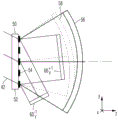
In a first embodiment, the structured pattern 54 is configured such that the input wave 42 is converted into an aspheric output wave 56, a spherical output wave 58 and a planar output wave 60 by diffraction at the structured pattern 54, as depicted in fig. 2. The spherical output wave and the planar output wave 60 act as a calibration wave, as will be explained below.
The output wave 56 is also plotted in fig. 1 and serves as a measurement wave for measuring the actual shape of the optical surface 12 of the optical element 14. To this end, the output wave 56 has a wavefront that is adapted to the desired shape of the optical surface 12. Thus, the output wave 56 is also referred to as the adapted measurement wave. As indicated above, the output wave 56 is aspheric and thus has a rotationally symmetric aspheric wavefront or a wavefront in the form of a free-form surface. The free-form surface within the meaning of the present application does not have rotational symmetry, as explained in the general part of the description.
Fig. 4 depicts in two cross-sectional views (once in yz in (a), and xy in (b)) the wave-vector k of an input wave 42 at a spatial coordinate i (x, y) on the diffractive structure pattern 54i(in), wave vector k of spherical output wave 58i(S) and wave vector k of aspheric output wave 56i(A) In that respect Here, the diffraction structure pattern 54 is arranged in the xy plane. Differential vector [ k ]i(A)-ki(in)]And a difference vector [ ki(S)-ki(in)]The angle therebetween is called angle αiThe angle α drawn in (a)i xzIs αiProjection in xz plane, angle α drawn in (b)i xyIs αiProjection in the xy plane.
Corner αi xy(i.e. projection in the xy planeAngle αi) The average of the absolute values of (a) over the spatial coordinates i (x, y) of the diffraction structure pattern 54 is referred to as an angle ω. According to one embodiment, the angle ω is greater than 5 °. Therefore, the following applies:

here, N represents the number of points i, on which an average value is formed. According to another embodiment, ω is greater than 10 ° or greater than 15 °.
As depicted in FIG. 5, the structural pattern 54 according to FIG. 2 includes a complex encoded phase grating fGComprising a plurality of phase functions f1To f4So as to be directed to a plurality of phase functions f1To f4Each individual one of which produces a corresponding diffracted wave. The diagram depicted in FIG. 5 shows the function f1To f4The contour line of (1). These contours of the phase function correspond to the grating lines of the respective diffraction grating. F depicted in FIG. 5GThe diagram of (a) shows an extremely enlarged cross section of the resulting pattern 54 according to fig. 2. In other words, a complex coded phase grating fGInfluencing the input wave 42 in such a way that the respective mutually independent diffracted waves of the first diffraction order pass through the phase function f1To f4Each of the defined diffraction gratings is produced. One can imagine a complex coded phase grating fGFor having a single phase function f superimposed at one point1To f4Several CGHs. The superposition of functionality corresponds to the operation S ═ W1*exp(i*f1)+W2*exp(i*f2)+W3*exp(i*f3)+W4*exp(i*f4). The intensities of the individual contributions are set by weights W1 to W4. The assumed unit is i. According to one embodiment of the invention, a binary phase grating (i.e., f)G0 or pi) phase grating f for implementing complex codingG。
The following applies to binary phase gratings: if Re { S }>0, then fGPi, otherwise f G0. According to another embodiment of the invention, a continuous phase grating is used to implement a complex coded phase grating fG. This situationThe following applies: f. ofGExp (i ∠ { S }). individual phase function f1、f2、f3And f4Has different amplitudes, in the present embodiment, the phase function f1And f2Each containing a weight W of 35%1And W2Phase function f3And f4Each containing a weight W of 15%3And W4。
Phase grating f according to fig. 5GPhase function f of1Producing an aspheric output wave 56. Phase grating fGPhase function f of2Producing a spherical output wave 58. The grating period corresponds very spatially to the phase function f on the diffraction structure pattern 54 according to fig. 21And f2。
Phase grating fGPhase function f of3And f4Is used to produce a signal of +1 respectivelystAnd-1stA linear grating of plane waves (P) of diffracted orders. Thus, the phase function f3Configured as a y-linear grating for producing a planar output wave deflected in the +/-y direction relative to the input wave 42. The planar output wave 60 plotted in fig. 2y +1And 60y -1To pass through a y-linear grating at +1stAnd-1stThe waves generated by the diffracted orders. Due to the selected cross-section in fig. 2, the phase function f cannot be seen in fig. 24 Planar output wave 60 produced by the formed x-linear gratingx +1And 60x -1But it is instead drawn in fig. 3.
Fig. 3 shows the output wave in the directional space generated by the center of the diffraction structure pattern 54 according to fig. 2. The x and y coordinates in the direction space are the x and y coordinates of the vector in the propagation direction normalized with respect to 1. The component of this direction vector is called the direction cosine. The following applies: -1. ltoreq. x.ltoreq.1, -1. ltoreq. y.ltoreq.1 and x2+y2≤1。
At the output wave 60y +1And 60y -1 Output wave 60 shifted in the + y or-y direction relative to aspheric output wave 56x +1And 60x -1Relative to the aspheric output wave 56-y and + x or-x. Output wave 60x +1And 60x -1Also plane wave and with +1stAnd-1stThe diffraction orders are formed by a phase function f constructed as an x-linear grating4And (4) generating. In the illustrated embodiment, the propagation direction of the spherical output wave 58 is tilted in the + x and + y directions compared to the aspherical output wave 56.
The measurement system 10 initially operates in a calibration mode prior to measuring the optical element 14 (the optical element 14 is disposed in the beam path of the aspheric output wave 56 during measurement, as depicted in fig. 1). In this way, the calibration sphere 62 is initially arranged on the output wave side with respect to the diffractive optical element 50 instead of the optical element 14 and is precise in the beam path of the spherical output wave 58, as shown in fig. 6.
The spherical output wave 58 is incident on a calibration sphere 62, the shape of which is accurately determined in absolute value. This absolute determination can be achieved, for example, by means of shearing techniques known to the person skilled in the art or by means of three-position tests likewise known.
After reflection at the calibration sphere 62, the spherical output wave 58 is directed through the diffractive optical element 50 and through the lens system 46 of the interferometer camera 45 to the detection area 47 of the camera chip 48 of the interferometer camera 45. An interference pattern is generated on the detection region 47 by superposition with the reference wave 40, from which interference pattern the deviation of the spherical output wave 58 from its expected wavefront in the form of an ideal spherical wave is determined by the evaluation device 49. Thus, the actual wavefront of the output wave 58 is determined in absolute value by the calibration sphere 62. The deviation of the spherical output wave 58 from its expected wavefront is stored as a calibration deviation K1.
Thus, the calibration sphere is again removed from the output wave side of the diffractive optical element 50, instead the plane mirror 64 is then arranged on the plane output wave 60y +1And 60y -1And 60x +1And 60x -1As in fig. 7 for the output wave 60 in (a)y +1And in (b) for the output wave 60y -1As depicted. The plane mirror 64 is in each case arranged such that a suitable output wave 60 is obtainedy +1、60y -1、60x +1Or 60x -1After passing through the diffractive optical element 50 in the beam path of the input wave 42, it is reflected to itself and returns to the interferometer 16 of the measuring system 10 and interferes with the reference wave 40 on the detection area 47 of the camera chip 48.
For two output waves 60x +1And 60x -1The same evaluation takes place. Thus, the phase function f is determined on the diffractive optical element 50 over the entire area of the diffractive structure pattern 544The y-coordinate of the deformation of (a). Therefore, the deformation of the x and y coordinates of the entire diffraction structure pattern 54 is derived from the deformation coordinates thus obtained. The deformation vector is stored as the other calibration offset K2 and is used to correct the spherical output wave 58 as well as the aspherical output wave 56.
Furthermore, the output wave 60y +1And 60y -1And an output wave 60x +1And 60x -1And the interference pattern of the spherical output wave 58 may be combined with each other, for example by summation, so that this can thus be used to determine the shape or profile deviation of the substrate surface of the diffractive optical element 50 with the diffractive structure pattern 54. The shape or contour deviations thus determined are also stored as further calibration deviations K3.
Finally, the optical surface 12 of the optical element 14 is measured by the measurement system 10. To this end, as shown in fig. 1, a test object in the form of an optical element 14 is arranged in the beam path of the aspherical output wave 56 such that the aspherical output wave 56 is incident self-aligned on the optical surface 12 and is reflected thereon. The wave reflected thereon returns as a return measurement wave 66 through the diffractive optical element 50 to the interferometer 16. The return measurement wave 66 interferes with the reference wave 40 over the detection area 47 and thus produces an interferogram. The interferogram is evaluated by an evaluation device 49 and this is used to determine the deviation of the actual shape of the optical surface 12 from its intended shape. All previously determined calibration deviations are taken into account during the evaluation.
By calibrating the deviations K1 and K2, the method makes it possible to eliminate substrate errors of the substrate 50 and errors caused by deformation of the diffractive structure pattern 54. In addition, by calibrating the deviation K3, the method makes it possible to reduce errors in the deviation of the shape or profile of the diffraction structure pattern 54.
Fig. 8 to 12 depict another embodiment of a diffractive optical element 50 for use in the measurement system 10 of fig. 1. As depicted in fig. 8, the diffractive structure pattern 54 of the diffractive optical element 50 is configured such that, by diffraction at the diffractive structure pattern 54, in addition to the aspherical output wave 56 also generated by the diffractive structure pattern of fig. 2, the input wave 42 is further converted into three spherical output waves 70, 72 and 74.
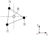
Fig. 9 depicts output waves 56, 70, 72, and 74 in directional space. As can be seen from this illustration, the spherical output waves 70, 72, and 74 are disposed around the aspheric output wave 56. Here, the direction vectors of the spherical output waves 70, 72, and 74 form a triangle. The direction vector of the aspheric output wave 56 is advantageously located in a triangle.
FIG. 10 depicts a complex phase encoded phase grating f according to the structural pattern 54 of FIG. 8GThe composition of (1). FIG. 10 shows a phase grating f similar to that of FIG. 5GIs a highly enlarged cross-section of the corresponding structure pattern 54. All depicted are square cross sections with edge lengths of 50 μm. As depicted in fig. 12, a diffractive optical element 50 according to one embodiment is arranged on a square substrate 52 having an edge length of 500 mm. In this embodiment, the diffractive structure pattern 54 is circular and mostly covers the substrate 52.
As shown in fig. 10, the complex coded phase grating f according to the structure pattern 54 of fig. 8GInvolving separate phase functions f1To f4. When the input wave 42 is radiated onto the diffractive optical element 50, the separated output waves are directed by suitable diffraction to the individual phase functions f1To f4And (4) generating.
In a suitable graph, firstly for the aspherical output wave 56(FF) and secondly for the spherical output waves 70, 72 and 74(SP1, SP2 and SP3), fig. 11 firstly shows the diffraction efficiency E of the diffractive optical element 50 according to fig. 8 during a single pass and secondly shows the contrast C of the interference pattern recorded by the camera chip 48 of the interferometric system during two passes through the diffractive optical element 50. In the graph, the phase function f is based on the generation of an aspheric output wave 56(FF)1The weights of (a) map the corresponding diffraction efficiency or contrast. The graph relates to 0.4% reflection by the fizeau element 36, 4% reflection by the optical surface 12 in the aspheric region, and 80% reflection by each of the optical surfaces of the calibration sphere adapted to the spherical output waves 70, 72, and 74. As can be seen from the graph, at f according to FIG. 101With a weight of 40%, this results in a diffraction efficiency in the single pass of slightly less than 25%, while the contrast is slightly greater than 90%. Then the contrast of the spherical output waves 70, 72 and 74 is close to 85%.
The measuring system when using the diffractive optical element 50 according to fig. 8 initially operates in a calibration mode, similar to the measurement of the optical surface 12 of the optical element 14 by means of the diffractive optical element 50 according to fig. 2. For this purpose, calibration spheres adapted to the spherical output waves 70, 72 and 74 are then arranged in a corresponding manner in the respective beam paths of the output waves 70, 72 and 74 and are measured in each case by interferometry. The interferometric measurements are stored in the evaluation device 49 as calibration measurement data for each of the spherical output waves 70, 72 and 74.
In the optical surface 12 of the test object in the form of the optical element 14, which is subsequently measured by means of the aspherical output wave 56, the measurement data thus obtained are evaluated by the evaluation device 49 taking into account the stored calibration measurement data. Because the calibration measurement data obtained during the measurement of the spherical output waves 70, 72, and 74 is taken into account, the manufacturing errors of the diffractive optical element 50 can be corrected in the measurement results of the optical surface 12, and therefore, the shape of the optical surface 12 can be determined with high accuracy. The manufacturing errors correctable here include deviations in the shape or profile of the substrate surface of the diffractive optical element 50 having the diffractive structure pattern 54, and deformation effects of the diffractive structure pattern 54.
Therefore, explicit measurement of the deformation error of the diffraction structure pattern 54 can be omitted. The option of calibrating the shape measurement of the optical surface 12 using three spherical waves enables a better error budget. This is due, inter alia, to the fact that deviations in the shape or profile of the diffractive structure pattern 54 produce very similar deviations in the spherical output waves 70, 72 and 74 and the aspherical output wave 56. Thus, these shape or contour deviations can be calibrated out over a large part.
The diffraction grating formed by the diffraction structure pattern 54 in the embodiment according to fig. 8 is constructed such that the fringe density of the grating lines averaged over a square measuring area of the diffraction grating with an edge length of 1mm has a variation over any square partial area with an edge length of 50 μm, which variation extends over a range of less than 20 line pairs/mm.
For example, as explained below with reference to fig. 12, a change in fringe density of a grating line can be determined. The diffractive structure pattern 54, which is arranged on the substrate 52 of the diffractive optical element 50 and according to one embodiment has the form of a circle with a diameter of approximately 500mm, is subdivided into individual square measuring areas MF, each having a side length of 1 mm. The measurement region MF is in turn subdivided into individual square part-regions TF, the respective side length of which is 50 μm.
Within the square part-area TF, the respective periodic distance d is determined at the measuring point i along the respective grating line GLiThe measurement points are in each case separated by 1 μm. Periodic distance diResulting from the sum of the width of the grating line GL at the measurement point i and the space to the next grating line adjacent to it on one side. Measured periodic distance diConverted to the fringe density value Di by forming the inverse. The thus obtained value of the fringe density Di is averaged over all measurement points i of all grating lines GL within the relevant partial region TF.
This occurs for all partial regions TF (e.g. 400 partial regions) within the square measurement region MF. Thus, the average fringe density D is determined for each partial region TF within the measurement region MFM. According to the above description, the average fringe density D of the individual partial regions TFMWith a range of less than 20 pairs per mm. Thus, the average fringe density D determined for each partial region TF within the measurement region MFMThe variation is less than 20 pairs/mm. For example, if the average fringe density DM200 line pairs/mm over all partial regions TF, the stripe density may vary at most in the range of 190 to 210 line pairs/mm according to the above-mentioned description.
Fig. 13 and 14 depict further characteristics of the diffractive structure pattern 54 in the embodiment according to fig. 8. Here, fig. 13 shows a square cross section with a side length of 50 μm of a diffraction grating formed by the diffraction structure pattern 54, and fig. 14 shows a cross section a of fig. 13 including one of the grating lines GL.
The diffraction grating depicted in fig. 13 has an average period distance p averaged over the diffraction grating, which is determined by the center-to-center distance between adjacent grating lines GL in each case. The periodic distance d may also be determined by averaging (described above with reference to FIG. 12)iTo determine the average period distance.
The grating lines GL have a wave-shaped form, to be precise such that the average wave period λ of the grating lines lies in a region of 3 to 20 times the average period distance d of the diffraction grating. In addition, the grating lines GL vary over a range Δ transverse to their longitudinal extent, which range Δ lies in the region of 0.1 to 3 times the average periodic distance d of the diffraction grating.
As depicted in fig. 14, the range Δ may be delimited by edge boundaries of the respective grating line GL which are approached by a straight boundary line 76, or by a deviation from the grating line GL at a trough at a peak determined with respect to the respective approached boundary line 76. The sum of these deviations, i.e. the deviation δ 1 at the peak and the deviation δ 2 at the trough, results in a range of variation Δ. However, the range Δ can also be determined by straight auxiliary lines 78 which are pushed from one side towards the grating lines until they adjoin the grating lines GL. Then, the maximum distance between the edge boundary of the grating line GL and the auxiliary line 78 also corresponds to the range Δ.
Fig. 15 and 16 show a depiction of the output waves in directional space that are generated by other embodiments of the diffraction fringe pattern 54. In both embodiments, in addition to the centrally arranged aspheric output wave 56 acting as a measurement wave, four other separate spherical output waves 70, 72, 74 and 80 acting as calibration waves are generated from the input wave 42 by diffraction at the fringe pattern 54. Here, the spherical output waves 70, 72, 74 and 80 are generated such that they are asymmetrically held free around the aspheric wave, i.e., respectively relative to a "space", which is defined by a mirror image of the corresponding point on the aspheric output wave 56 in the view plane in the direction space. In other words, the respective average propagation directions of the pairs of spherical output waves 70, 72, 74 and 80 are not in each case arranged symmetrically with respect to one another with respect to an axis defined by the average propagation direction of the aspherical output wave 56.
In the embodiment according to fig. 15, in the diagram plane in the direction space, the spherical output waves 80 and 70 are arranged symmetrically with respect to the spherical output waves 72 and 74 with respect to an axis of symmetry arranged transversely with respect to the mean propagation direction of the aspherical output wave 56. In the embodiment according to fig. 16, this symmetry is missing, but the spherical output waves 70 and 74 and 72 and 76 are arranged in each case on a straight line which extends through the aspherical output wave 56 in the diagram plane in the direction space.
The use of four aspheric output waves allows a configuration to be found in which the sensitivity to grating defects is minimized during shape measurement of the optical surface 12 of the calibration optical element 14 due to the additional degrees of freedom compared to using only three spherical output waves.
According to one embodiment variant of the diffractive optical element 50 in one of the above-described embodiments, the diffractive structure pattern 54 is implemented as a multi-stage phase grating, as in fig. 17 using the phase grating f of fig. 10GAre depicted. As will be clear to a person skilled in the art, a multi-level phase grating is to be understood to mean a phase grating having at least one intermediate level between the highest and lowest level. Thus, such a phase grating has at least three stages, and the embodiment shown in fig. 17 provides four stages. The use of a multi-stage phase grating makes it possible to at least partially compensate or even overcompensate for the loss of diffraction efficiency caused by the complex encoding undertaken.
Fig. 18 and 19 depict an embodiment of an optical element 14 manufactured according to the invention in the form of a lens element or a mirror, in particular a mirror for an EUV projection exposure apparatus. The optical element 14 has an optical surface 12 formed as a free-form surface. During manufacturing, the optical surface 12 of the optical element 14 is initially manufactured to a predetermined desired shape that approximates the form of the free-form surface, depending on the accuracy of the manufacturing. The approaching surface 12 is then measured by the interferometric measuring system 10 using the diffractive optical element 50 in one embodiment according to the invention, so that the deviation of the surface from the intended shape is determined with high accuracy. The surface 12 is further processed at appropriate points based on the measurement results so that the surface has the specifications specified below.
In fig. 18, the diameter d of the optical surface 12 can be seen, which is nearly circular, and fig. 18 shows a top view of the optical element 14. In the depicted embodiment, the diameter d is about 600 mm. Fig. 19 shows a schematic cross-section of the optical element along the axis 80 of the optical element 14. The axis 80 is the axis of rotation of a rotationally symmetric sphere 82 having a desired shape 84 best suited to the optical surface 12 and is arranged in the z-direction in the figure. As already mentioned above, the expected shape 84 has the form of a free-form surface and is therefore not rotationally symmetric. The deviation of the optical surface 12 from the intended shape 84 shown in fig. 19 is greatly exaggerated and depicted in a schematic manner for illustrative purposes.
The maximum deviation Δ of the intended shape 84 from the most suitable rotationally symmetric sphere 82 is about 6 μm in this embodiment, and is therefore greater than 5 μm. The deviation of the actual shape of the optical surface 12 from the expected shape 84 is described by a 2-dimensional deviation D (x, y), where x and y represent coordinates on the surface 12. The deviation D (x, y) from oscillation with a vibration wavelength between D/100 (i.e. about 5mm) and D/5 (i.e. about 100mm) is at most 0.05 nm.
If the deviation D (x, y) is transformed from real space into frequency space by fourier transformation, a function D (v) is obtained, where v denotes the frequency. The amplitude of the function d (v) in the region between the frequencies corresponding to the border values of the above-mentioned vibration wavelength range is therefore at most 0.05 nm.
REFERENCE SIGNS LIST
10 interferometric measuring system
12 optical surface
14 optical element
16 interferometer
18 light source
20 illumination radiation
21 laser
22 laser beam
24-focus lens
26 diaphragm
28 diverging light Beam
30 lens element group
32 optical axis
34 beam splitter
36 Fizeau element
38 fizeau area
40 reference wave
42 input wave
44 plane wave front
45 interferometer camera
46 lens system
47 detection area
48 camera chip
50 diffractive optical element
52 substrate
54 diffraction Structure Pattern
56 aspheric output wave
58 spherical output
60x +1Plane output wave
60x -1Plane output wave
60y +1Plane output wave
60y -1Plane output wave
62 calibration ball
64 plane reflector
66 return measurement wave
70 spherical output wave
72 spherical output wave
74 spherical output wave
76 closely straight boundary line
78 straight auxiliary line
80 rotating shaft
82 most suitable rotationally symmetric aspheric surface
84 desired shape
Claims (6)
1. A method for determining a deviation of an actual shape from an expected shape of an optical surface of an optical element, comprising the steps of:
-generating an input wave;
-arranging a diffractive optical element in the beam path of the input wave such that the input wave is converted into at least a measurement wave by interaction with the diffractive optical element, the measurement wave being adapted to the intended shape of the optical surface, and a reference wave is generated from the input wave at the diffractive optical element with Littrow reflection;
-arranging the optical surface in the beam path of the adapted measurement wave and measuring the wavefront of the adapted measurement wave after interaction with the optical surface by interferometry using a reference wave as reference.
2. The method according to claim 1, wherein the first step is carried out in a single step,
wherein the input wave is further converted into at least one calibration wave by interaction with the diffractive optical element.
3. The method according to claim 1 or 2,
wherein the diffractive optical element comprises a complex encoded phase grating.
4. A diffractive optical element having a substrate and a pattern of diffractive structures arranged thereon, wherein the pattern of diffractive structures is configured to convert a planar or spherical input wave radiated thereto into at least an aspherical output wave adapted to the intended shape of an optical surface to be measured, the diffractive structures being further configured to generate a reference wave from the input wave in Littrow reflection, the reference wave being configured to serve as a reference to measure the wavefront of the aspherical output wave after interaction with the optical surface by interferometry.
5. The diffractive optical element as claimed in claim 4, configured to convert the output wave also into at least one calibration wave in the form of a plane wave or a spherical wave.
6. An interferometry system for determining a deviation of an actual shape from an expected shape of an optical surface of an optical element, comprising:
-a light source for generating an input wave;
-a diffractive optical element arranged in the beam path of the input wave such that the input wave is converted by interaction with the diffractive optical element into at least a measurement wave which is adapted to the intended shape of the optical surface and at which a reference wave is generated from the input wave with Littrow reflection; and
an interferometer for measuring the wavefront of the adapted measurement wave after interaction with the optical surface using the reference wave as a reference.
Applications Claiming Priority (5)
| Application Number | Priority Date | Filing Date | Title |
|---|---|---|---|
| US201261707014P | 2012-09-28 | 2012-09-28 | |
| DE102012217800.7A DE102012217800A1 (en) | 2012-09-28 | 2012-09-28 | Diffractive optical element and measuring method |
| US61/707,014 | 2012-09-28 | ||
| DE102012217800.7 | 2012-09-28 | ||
| CN201380051045.5A CN104685317B (en) | 2012-09-28 | 2013-09-27 | Diffraction optical element and interferometric method |
Related Parent Applications (1)
| Application Number | Title | Priority Date | Filing Date |
|---|---|---|---|
| CN201380051045.5A Division CN104685317B (en) | 2012-09-28 | 2013-09-27 | Diffraction optical element and interferometric method |
Publications (2)
| Publication Number | Publication Date |
|---|---|
| CN107816939A CN107816939A (en) | 2018-03-20 |
| CN107816939B true CN107816939B (en) | 2020-04-14 |
Family
ID=50276236
Family Applications (2)
| Application Number | Title | Priority Date | Filing Date |
|---|---|---|---|
| CN201380051045.5A Active CN104685317B (en) | 2012-09-28 | 2013-09-27 | Diffraction optical element and interferometric method |
| CN201711103826.0A Active CN107816939B (en) | 2012-09-28 | 2013-09-27 | Diffractive optical element and interferometric method |
Family Applications Before (1)
| Application Number | Title | Priority Date | Filing Date |
|---|---|---|---|
| CN201380051045.5A Active CN104685317B (en) | 2012-09-28 | 2013-09-27 | Diffraction optical element and interferometric method |
Country Status (7)
| Country | Link |
|---|---|
| US (1) | US20150198438A1 (en) |
| EP (1) | EP2901101B1 (en) |
| JP (3) | JP6105731B2 (en) |
| KR (2) | KR101869141B1 (en) |
| CN (2) | CN104685317B (en) |
| DE (1) | DE102012217800A1 (en) |
| WO (1) | WO2014048574A2 (en) |
Families Citing this family (37)
| Publication number | Priority date | Publication date | Assignee | Title |
|---|---|---|---|---|
| US9234741B2 (en) * | 2014-04-01 | 2016-01-12 | Dmetrix, Inc. | Interferometric apparatus with computer-generated hologram for measuring non-spherical surfaces |
| DE102014117511A1 (en) * | 2014-11-28 | 2016-06-02 | Friedrich-Schiller-Universität Jena | Method and apparatus for interferometric testing |
| CN104656173B (en) * | 2015-02-09 | 2017-05-03 | 浙江大学 | Randomly-coded hybrid grating based on light flux constraint |
| DE102015202676B4 (en) * | 2015-02-13 | 2016-09-22 | Carl Zeiss Smt Gmbh | Interferometric measuring device |
| DE102015202695A1 (en) * | 2015-02-13 | 2016-08-18 | Carl Zeiss Smt Gmbh | Test device and method for testing a mirror |
| DE102016203562A1 (en) | 2016-03-04 | 2017-09-07 | Carl Zeiss Smt Gmbh | Measuring method and measuring arrangement for an imaging optical system |
| DE102015220588A1 (en) | 2015-10-22 | 2017-04-27 | Carl Zeiss Smt Gmbh | Measuring method and measuring arrangement for an imaging optical system |
| EP3298446A2 (en) * | 2015-05-20 | 2018-03-28 | Carl Zeiss SMT GmbH | Measuring method and measuring arrangement for an imaging optical system |
| DE102015209490A1 (en) | 2015-05-22 | 2016-11-24 | Carl Zeiss Smt Gmbh | Interferometric measuring arrangement |
| DE102015209489A1 (en) | 2015-05-22 | 2016-06-02 | Carl Zeiss Smt Gmbh | Interferometric measuring device |
| DE102015222366A1 (en) | 2015-11-12 | 2017-05-18 | Universität Stuttgart | Tilted object waves using and a Fizeau interferometer lens having interferometer |
| DE102017204719A1 (en) * | 2017-03-21 | 2018-09-27 | Carl Zeiss Smt Gmbh | Metrology target |
| GB201708100D0 (en) * | 2017-05-19 | 2017-07-05 | Sintef | Input device |
| DE102017216401A1 (en) | 2017-09-15 | 2018-10-11 | Carl Zeiss Smt Gmbh | Computer-generated hologram (CGH), as well as method for its production |
| DE102017217369A1 (en) | 2017-09-29 | 2019-04-04 | Carl Zeiss Smt Gmbh | Compensation optics for an interferometric measuring system |
| DE102018203795A1 (en) | 2018-03-13 | 2018-05-03 | Carl Zeiss Smt Gmbh | Interferometric measuring arrangement for determining a surface shape |
| DE102018209175B4 (en) | 2018-06-08 | 2024-01-04 | Carl Zeiss Smt Gmbh | Computer-generated hologram (CGH), interferometric test arrangement, and method for characterizing the surface shape of an optical element |
| DE102018221406A1 (en) * | 2018-12-11 | 2019-12-24 | Carl Zeiss Smt Gmbh | Diffractive optical element and method for its production |
| DE102019204096A1 (en) * | 2019-03-26 | 2020-10-01 | Carl Zeiss Smt Gmbh | Measurement method for the interferometric determination of a surface shape |
| DE102019212614A1 (en) | 2019-08-22 | 2021-02-25 | Carl Zeiss Smt Gmbh | Method for calibrating a measuring device |
| DE102019214979A1 (en) * | 2019-09-30 | 2021-04-01 | Carl Zeiss Smt Gmbh | Measuring device for the interferometric determination of a surface shape |
| DE102019215707A1 (en) * | 2019-10-14 | 2021-04-15 | Carl Zeiss Smt Gmbh | Method and device for characterizing the surface shape of an optical element |
| DE102019216447A1 (en) | 2019-10-25 | 2019-12-19 | Carl Zeiss Smt Gmbh | Interferometric test arrangement for testing the surface shape of a test object |
| WO2021141730A1 (en) * | 2020-01-10 | 2021-07-15 | Applied Materials, Inc. | A method to determine line angle and rotation of multiple patterning |
| DE102020200628A1 (en) * | 2020-01-21 | 2021-07-22 | Carl Zeiss Smt Gmbh | Measuring device for interferometric shape measurement |
| DE102020202623A1 (en) * | 2020-03-02 | 2021-03-25 | Carl Zeiss Smt Gmbh | Method for the complex coding of a computer-generated hologram (CGH) |
| DE102020205891A1 (en) * | 2020-05-11 | 2021-11-11 | Carl Zeiss Smt Gmbh | Method and measuring device for interferometric measurement of a shape of a surface |
| DE102020209580B3 (en) | 2020-07-30 | 2021-09-23 | Carl Zeiss Smt Gmbh | Method for determining a wavefront generated by means of a diffractive optical element, method for producing a diffractive optical element and measuring device for interferometric shape measurement of a surface of a test object |
| DE102020213762B3 (en) | 2020-11-02 | 2021-09-23 | Carl Zeiss Smt Gmbh | Diffractive optical element for an interferometric measuring device |
| DE102021200112A1 (en) | 2021-01-08 | 2021-12-16 | Carl Zeiss Smt Gmbh | Clamping system |
| DE102021202820B3 (en) | 2021-03-23 | 2022-03-03 | Carl Zeiss Smt Gmbh | Interferometric measurement method and interferometric measurement arrangement |
| DE102021202909A1 (en) | 2021-03-25 | 2022-09-29 | Carl Zeiss Smt Gmbh | Measuring device for interferometric measuring of a surface shape |
| DE102021202911A1 (en) | 2021-03-25 | 2022-09-29 | Carl Zeiss Smt Gmbh | Measuring device for interferometric measuring of a surface shape |
| DE102021208880A1 (en) | 2021-08-13 | 2023-02-16 | Carl Zeiss Smt Gmbh | Diffractive optical element for generating a test wave |
| DE102021212778A1 (en) | 2021-11-12 | 2022-11-17 | Carl Zeiss Smt Gmbh | Diffractive optical element with a structure pattern |
| DE102022209887A1 (en) | 2022-09-20 | 2023-08-24 | Carl Zeiss Smt Gmbh | Method and device for characterizing the surface shape of an optical element |
| DE102022214271B4 (en) | 2022-12-22 | 2024-02-29 | Carl Zeiss Smt Gmbh | Device for the interferometric determination of a fit error of an optical surface |
Citations (6)
| Publication number | Priority date | Publication date | Assignee | Title |
|---|---|---|---|---|
| US6005667A (en) * | 1996-07-23 | 1999-12-21 | Canon Kabushiki Kaisha | Optical displacement measurement apparatus and information recording apparatus |
| CN1973180A (en) * | 2004-06-23 | 2007-05-30 | 莱卡地球系统公开股份有限公司 | Scanner system and method for registering surfaces |
| CN1987341A (en) * | 2005-12-23 | 2007-06-27 | 安捷伦科技有限公司 | Littrow interferometer |
| CN101495833A (en) * | 2006-07-28 | 2009-07-29 | 卡尔蔡司Smt股份公司 | Optical element and method of calibrating a measuring apparatus comprising a wave shaping structure |
| CN101687302A (en) * | 2007-07-09 | 2010-03-31 | 卡尔蔡司Smt股份公司 | Method of measuring a deviation of an optical surface from a target shape |
| US7948638B2 (en) * | 2006-09-19 | 2011-05-24 | Zygo Corporation | Scanning interferometric methods and apparatus for measuring aspheric surfaces and wavefronts |
Family Cites Families (31)
| Publication number | Priority date | Publication date | Assignee | Title |
|---|---|---|---|---|
| JPS6377014A (en) * | 1986-09-19 | 1988-04-07 | Yokogawa Electric Corp | Optical scanning device using aspherical hologram |
| CN1019419B (en) * | 1987-02-20 | 1992-12-09 | 株式会社岛津制作所 | Method and apparatus for producing holographic grating |
| JPH01208292A (en) * | 1988-02-16 | 1989-08-22 | Sanoyasu:Kk | Asymmetry stern shape ship |
| US4958463A (en) * | 1988-06-06 | 1990-09-25 | United Technologies Corporation | Optical surface quality improving arrangement |
| JPH04336090A (en) * | 1991-05-10 | 1992-11-24 | Namco Ltd | Game device using concave mirror |
| JP3187093B2 (en) * | 1991-09-27 | 2001-07-11 | キヤノン株式会社 | Position shift measuring device |
| JP2709350B2 (en) * | 1992-05-28 | 1998-02-04 | 大日本スクリーン製造株式会社 | Contact printer |
| US5496616A (en) * | 1994-12-27 | 1996-03-05 | Xerox Corporation | Optical element for correcting non-uniform diffraction efficiency in a binary diffractive optical element |
| JP3590142B2 (en) * | 1995-07-21 | 2004-11-17 | オリンパス株式会社 | Interferometer device |
| JP2000267295A (en) * | 1999-03-15 | 2000-09-29 | Fujitsu Ltd | Exposing method and device therefor |
| JP2003035526A (en) * | 2001-05-18 | 2003-02-07 | Nikon Corp | Transmissive zone plate, reflective zone plate, shape measuring method, interference measuring device, and manufacturing method for projection optical system |
| US6771375B2 (en) * | 2001-06-20 | 2004-08-03 | Zygo Corporation | Apparatus and method for measuring aspherical optical surfaces and wavefronts |
| US6972849B2 (en) * | 2001-07-09 | 2005-12-06 | Kuechel Michael | Scanning interferometer for aspheric surfaces and wavefronts |
| EP1316789A1 (en) * | 2001-12-03 | 2003-06-04 | Universität Stuttgart | Calibration of a diffractive compensation or absolute normal element ( twin or dual CGH ) by faults in the wavefront of the auxiliary spherical wave |
| KR100449711B1 (en) * | 2001-12-21 | 2004-09-22 | 삼성전자주식회사 | Apparatus and method for measurement of aspheric surface with hologram and concave surface |
| JP2003269909A (en) * | 2002-03-12 | 2003-09-25 | Nikon Corp | Method of measuring shape, instrument for measuring interference, method of manufacturing projection optical system, and projection exposure unit |
| JP3891872B2 (en) * | 2002-04-04 | 2007-03-14 | 株式会社ミツトヨ | Micro periodic structure evaluation apparatus and micro periodic structure evaluation method |
| US7158215B2 (en) * | 2003-06-30 | 2007-01-02 | Asml Holding N.V. | Large field of view protection optical system with aberration correctability for flat panel displays |
| JP2007527997A (en) * | 2004-03-06 | 2007-10-04 | マイケル トレイナー, | Method and apparatus for determining particle size and shape |
| TW200630604A (en) * | 2005-01-06 | 2006-09-01 | Matsushita Electric Ind Co Ltd | Method and apparatus for inspection of optical component |
| JP2007010609A (en) * | 2005-07-04 | 2007-01-18 | Olympus Corp | Method for manufacturing aspheric lens, eccentricity measuring method of aspheric lens, eccentricity measuring device, and aspheric lens manufactured by this method |
| WO2008110239A1 (en) * | 2007-03-15 | 2008-09-18 | Carl Zeiss Smt Ag | Diffractive component, interferometer arrangement, method for qualifying a dual diffraction grating, method of manufacturing an optical element, and interferometric method |
| US7602502B2 (en) * | 2007-04-11 | 2009-10-13 | Carl Zeiss Smt Ag | Methods of testing and manufacturing optical elements |
| DE102008029970A1 (en) * | 2008-06-26 | 2009-12-31 | Carl Zeiss Smt Ag | Projection exposure apparatus for microlithography and method for monitoring a lateral imaging stability |
| US7889356B2 (en) * | 2008-12-09 | 2011-02-15 | Zygo Corporation | Two grating lateral shearing wavefront sensor |
| DE102009008644A1 (en) * | 2009-02-12 | 2010-11-18 | Carl Zeiss Smt Ag | Imaging optics and projection exposure system for microlithography with such an imaging optics |
| WO2011032572A1 (en) * | 2009-09-18 | 2011-03-24 | Carl Zeiss Smt Gmbh | Method of measuring a shape of an optical surface and interferometric measuring device |
| DE102010008629B4 (en) * | 2010-02-17 | 2020-09-03 | Carl Zeiss Meditec Ag | Reflection-free imaging optics for optical devices, especially in ophthalmology |
| KR101929836B1 (en) * | 2010-04-01 | 2018-12-18 | 시리얼 테크놀로지즈 에스.에이. | Method and device for encoding three-dimensional scenes which include transparent objects in a holographic system |
| CN102095504B (en) * | 2010-12-07 | 2012-07-11 | 四川大学 | Ring common-path point diffraction interferometer based on spatial phase modulation |
| CN102620842B (en) * | 2012-04-10 | 2013-10-30 | 中国科学院光电技术研究所 | Device for detecting optical surface shapes of hole diffraction spherical waves |
-
2012
- 2012-09-28 DE DE102012217800.7A patent/DE102012217800A1/en not_active Ceased
-
2013
- 2013-09-27 KR KR1020157007564A patent/KR101869141B1/en active IP Right Grant
- 2013-09-27 EP EP13776953.5A patent/EP2901101B1/en active Active
- 2013-09-27 WO PCT/EP2013/002904 patent/WO2014048574A2/en active Application Filing
- 2013-09-27 JP JP2015532335A patent/JP6105731B2/en active Active
- 2013-09-27 CN CN201380051045.5A patent/CN104685317B/en active Active
- 2013-09-27 KR KR1020187016531A patent/KR102056552B1/en active IP Right Grant
- 2013-09-27 CN CN201711103826.0A patent/CN107816939B/en active Active
-
2015
- 2015-03-27 US US14/670,632 patent/US20150198438A1/en not_active Abandoned
-
2017
- 2017-03-02 JP JP2017039346A patent/JP6462025B2/en active Active
-
2018
- 2018-12-26 JP JP2018243265A patent/JP2019090819A/en active Pending
Patent Citations (6)
| Publication number | Priority date | Publication date | Assignee | Title |
|---|---|---|---|---|
| US6005667A (en) * | 1996-07-23 | 1999-12-21 | Canon Kabushiki Kaisha | Optical displacement measurement apparatus and information recording apparatus |
| CN1973180A (en) * | 2004-06-23 | 2007-05-30 | 莱卡地球系统公开股份有限公司 | Scanner system and method for registering surfaces |
| CN1987341A (en) * | 2005-12-23 | 2007-06-27 | 安捷伦科技有限公司 | Littrow interferometer |
| CN101495833A (en) * | 2006-07-28 | 2009-07-29 | 卡尔蔡司Smt股份公司 | Optical element and method of calibrating a measuring apparatus comprising a wave shaping structure |
| US7948638B2 (en) * | 2006-09-19 | 2011-05-24 | Zygo Corporation | Scanning interferometric methods and apparatus for measuring aspheric surfaces and wavefronts |
| CN101687302A (en) * | 2007-07-09 | 2010-03-31 | 卡尔蔡司Smt股份公司 | Method of measuring a deviation of an optical surface from a target shape |
Also Published As
| Publication number | Publication date |
|---|---|
| CN104685317A (en) | 2015-06-03 |
| JP6105731B2 (en) | 2017-03-29 |
| KR20180069923A (en) | 2018-06-25 |
| KR101869141B1 (en) | 2018-06-19 |
| JP2019090819A (en) | 2019-06-13 |
| CN104685317B (en) | 2017-12-22 |
| JP2015535930A (en) | 2015-12-17 |
| DE102012217800A1 (en) | 2014-04-03 |
| KR20150046282A (en) | 2015-04-29 |
| EP2901101B1 (en) | 2022-05-18 |
| WO2014048574A2 (en) | 2014-04-03 |
| JP2017167133A (en) | 2017-09-21 |
| EP2901101A2 (en) | 2015-08-05 |
| CN107816939A (en) | 2018-03-20 |
| JP6462025B2 (en) | 2019-01-30 |
| WO2014048574A3 (en) | 2014-05-30 |
| US20150198438A1 (en) | 2015-07-16 |
| KR102056552B1 (en) | 2019-12-16 |
Similar Documents
| Publication | Publication Date | Title |
|---|---|---|
| CN107816939B (en) | Diffractive optical element and interferometric method | |
| US8345262B2 (en) | Method and apparatus for determining a deviation of an actual shape from a desired shape of an optical surface | |
| US8089634B2 (en) | Optical element and method of calibrating a measuring apparatus comprising a wave shaping structure | |
| CN109061887B (en) | Diffractive optical element and measuring device | |
| US20060274325A1 (en) | Method of qualifying a diffraction grating and method of manufacturing an optical element | |
| US7848031B2 (en) | Hologram and method of manufacturing an optical element using a hologram | |
| Shimizu | Laser interference lithography for fabrication of planar scale gratings for optical metrology | |
| US7072042B2 (en) | Apparatus for and method of measurement of aspheric surfaces using hologram and concave surface | |
| US7436520B1 (en) | Method of calibrating an interferometer optics and of processing an optical element having an optical surface | |
| US9557241B2 (en) | Wavefront aberration measuring method, wavefront aberration measuring apparatus and optical element manufacturing method | |
| US7349102B2 (en) | Methods and apparatus for reducing error in interferometric imaging measurements | |
| US7061626B1 (en) | Method of manufacturing an optical element using a hologram | |
| US20030067684A1 (en) | Method of aligning optical system using a hologram and apparatus therefor | |
| JP2022551063A (en) | Measuring device for interferometric measurement of surface shape | |
| Burkhardt et al. | Manufacturing method for monolithic freeform Offner-gratings for hyper-spectral imaging | |
| JP5948949B2 (en) | Diffractive optical element and measuring device | |
| Poleshchuk et al. | Methods for certification of CGH fabrication | |
| CN116075682A (en) | Method for determining a wavefront generated by a diffractive optical element | |
| Hwang et al. | Visibility optimization of phase-shifting diffraction-grating interferometer | |
| Feng et al. | Error analysis for aspheric surface testing system |
Legal Events
| Date | Code | Title | Description |
|---|---|---|---|
| PB01 | Publication | ||
| PB01 | Publication | ||
| SE01 | Entry into force of request for substantive examination | ||
| SE01 | Entry into force of request for substantive examination | ||
| GR01 | Patent grant | ||
| GR01 | Patent grant |