CN107708823B - Game system - Google Patents
Game system Download PDFInfo
- Publication number
- CN107708823B CN107708823B CN201680033735.1A CN201680033735A CN107708823B CN 107708823 B CN107708823 B CN 107708823B CN 201680033735 A CN201680033735 A CN 201680033735A CN 107708823 B CN107708823 B CN 107708823B
- Authority
- CN
- China
- Prior art keywords
- detection
- toy
- identification
- identification element
- data processing
- Prior art date
- Legal status (The legal status is an assumption and is not a legal conclusion. Google has not performed a legal analysis and makes no representation as to the accuracy of the status listed.)
- Active
Links
Images


Classifications
-
- A—HUMAN NECESSITIES
- A63—SPORTS; GAMES; AMUSEMENTS
- A63F—CARD, BOARD, OR ROULETTE GAMES; INDOOR GAMES USING SMALL MOVING PLAYING BODIES; VIDEO GAMES; GAMES NOT OTHERWISE PROVIDED FOR
- A63F13/00—Video games, i.e. games using an electronically generated display having two or more dimensions
- A63F13/90—Constructional details or arrangements of video game devices not provided for in groups A63F13/20 or A63F13/25, e.g. housing, wiring, connections or cabinets
- A63F13/98—Accessories, i.e. detachable arrangements optional for the use of the video game device, e.g. grip supports of game controllers
-
- A—HUMAN NECESSITIES
- A63—SPORTS; GAMES; AMUSEMENTS
- A63F—CARD, BOARD, OR ROULETTE GAMES; INDOOR GAMES USING SMALL MOVING PLAYING BODIES; VIDEO GAMES; GAMES NOT OTHERWISE PROVIDED FOR
- A63F13/00—Video games, i.e. games using an electronically generated display having two or more dimensions
- A63F13/20—Input arrangements for video game devices
- A63F13/21—Input arrangements for video game devices characterised by their sensors, purposes or types
-
- A—HUMAN NECESSITIES
- A63—SPORTS; GAMES; AMUSEMENTS
- A63F—CARD, BOARD, OR ROULETTE GAMES; INDOOR GAMES USING SMALL MOVING PLAYING BODIES; VIDEO GAMES; GAMES NOT OTHERWISE PROVIDED FOR
- A63F13/00—Video games, i.e. games using an electronically generated display having two or more dimensions
- A63F13/20—Input arrangements for video game devices
- A63F13/24—Constructional details thereof, e.g. game controllers with detachable joystick handles
-
- A—HUMAN NECESSITIES
- A63—SPORTS; GAMES; AMUSEMENTS
- A63F—CARD, BOARD, OR ROULETTE GAMES; INDOOR GAMES USING SMALL MOVING PLAYING BODIES; VIDEO GAMES; GAMES NOT OTHERWISE PROVIDED FOR
- A63F13/00—Video games, i.e. games using an electronically generated display having two or more dimensions
- A63F13/40—Processing input control signals of video game devices, e.g. signals generated by the player or derived from the environment
- A63F13/42—Processing input control signals of video game devices, e.g. signals generated by the player or derived from the environment by mapping the input signals into game commands, e.g. mapping the displacement of a stylus on a touch screen to the steering angle of a virtual vehicle
-
- A—HUMAN NECESSITIES
- A63—SPORTS; GAMES; AMUSEMENTS
- A63F—CARD, BOARD, OR ROULETTE GAMES; INDOOR GAMES USING SMALL MOVING PLAYING BODIES; VIDEO GAMES; GAMES NOT OTHERWISE PROVIDED FOR
- A63F13/00—Video games, i.e. games using an electronically generated display having two or more dimensions
- A63F13/60—Generating or modifying game content before or while executing the game program, e.g. authoring tools specially adapted for game development or game-integrated level editor
- A63F13/65—Generating or modifying game content before or while executing the game program, e.g. authoring tools specially adapted for game development or game-integrated level editor automatically by game devices or servers from real world data, e.g. measurement in live racing competition
-
- A—HUMAN NECESSITIES
- A63—SPORTS; GAMES; AMUSEMENTS
- A63H—TOYS, e.g. TOPS, DOLLS, HOOPS OR BUILDING BLOCKS
- A63H33/00—Other toys
- A63H33/04—Building blocks, strips, or similar building parts
- A63H33/06—Building blocks, strips, or similar building parts to be assembled without the use of additional elements
- A63H33/08—Building blocks, strips, or similar building parts to be assembled without the use of additional elements provided with complementary holes, grooves, or protuberances, e.g. dovetails
Abstract
A gaming system, comprising: a data processing system configured to execute program instructions that allow a user to participate in a digital game; a physical toy; and a detection device configured to detect the presence of the toy within a detection area of the detection device; wherein the toy comprises two or more identification elements that are detectable by the detection device when each identification element is positioned within the detection area, wherein the toy is configured to allow a user to selectively position the toy while a user-selected subset of one or more of the identification elements is within the detection area; and wherein the data processing system is configured to control the digital game in response to the detected subset of identification elements.
Description
Technical Field
The present invention relates to a game system.
Background
Gaming systems, and in particular gaming systems in which users operate virtual characters in a virtual environment, have become increasingly popular among children and adult users. There are a variety of such gaming systems that may be executed by a data processing system, such as a gaming console, handheld gaming device, desktop computer, portable computer, tablet computer, or mobile telephone. It is often desirable to make such systems more and more interesting, entertaining and/or educational.
Several attempts have been made to control virtual games through physical toys. For example, uk patent application GB 2365796 discloses a game system comprising a toy storing toy information, a reader for detecting the toy information by means of a contactless data transmission system, and a game apparatus. The game device executes a game in which characters representing toys appear in accordance with toy information detected by the reader.
In many gaming systems, various virtual objects may become available to a player during game play (e.g., when the virtual object evolves to a higher level object, when the player gains virtual equipment, etc.). Thus, during play of a virtual game, it is desirable to be able to represent different virtual objects by corresponding physical objects. It is also desirable to provide the user with additional control options for controlling game play.
Disclosure of Invention
According to a first aspect, embodiments of a gaming system are disclosed herein, comprising:
-a data processing system configured to execute program instructions for allowing a user to participate in a digital game;
-a physical toy; and
-a detection device configured to detect the presence of the toy within a detection area of the detection device;
wherein the toy comprises two or more identification elements, each identification element being detectable by the detection device when the identification element is disposed within the detection area, wherein the toy is configured to allow a user to selectively position the toy while a user-selected subset of one or more of the identification elements is within the detection area; and wherein the data processing system is configured to control the digital game in response to the detected subset of identification elements.
The subset of identification elements may be a single identification element or a plurality of identification elements, but less than the total number of identification elements comprised in the physical toy, i.e. the subset may be a proper subset; the subset may even include all identification elements contained in the physical toy. The toy is configured such that the user may selectively position the toy while only a subset of the identification elements are within the detection area of the detection device, and identification elements that are not of the user-selected subset (if any) are not within the detection area of the detection device. In some embodiments, the physical toy is configured such that the toy may only be positioned, at least in one configuration, such that each time a proper subset of the identification elements (e.g., only a single identification element) are within the detection area. In some embodiments, the identification elements of a subset may be positioned within the same detection area of the detection device. In some embodiments, the detection device comprises more than one detection area, and the toy may be configured to allow a user to position the toy with a subset of the identification elements in respective ones of the detection areas, i.e. not necessarily in the same detection area.
The physical toy may be a coherent structure, wherein two or more identification elements are physically interconnected with the structure, e.g. mounted on the structure, integrated into the structure, etc. Some or all of the identification elements may be removably attached to the structure, for example such that they may be repeatedly attached to and detached from the same toy and/or different toys, for example at the same or different locations on the toy. Alternatively or additionally, some or all of the identification elements may be integrated into the structure such that they cannot be removed or separated from the structure.
In some embodiments, the physical toy is a toy construction model constructed from a plurality of construction elements such that the construction elements are detachably interconnected to each other so as to form a coherent structure.
In some embodiments, the toy structure includes a first portion and a second portion movably interconnected with one another, e.g., hinged with respect to one another, rotatable with respect to one another, slidable or otherwise movable with respect to one another. The first portion may include a first identification element of the two or more identification elements and the second portion may include a second identification element of the two or more identification elements. The second part may be brought into the first position relative to the first part such that the second identification element is not within the detection area of the detection device when said first identification element is positioned within the detection area of the detection device. The second part can be brought into a second position relative to the first part, so that when the first identification element is positioned within the detection area of the detection device, the second identification element is also within the same or a different detection area of the detection device. The first and second parts can be brought into respective positions relative to each other, so that the identification elements can be selectively positioned in the same or different detection areas. For example, the portions may be moved in order to adjust the relative distance of the identification elements to each other, for example between a first configuration, in which the identification elements are brought close to each other and fitted within the same detection area, and a second configuration, in which the identification elements are distanced from each other and may be positioned simultaneously in the respective detection areas.
The identification element may comprise information related to the identification element and/or related to the physical toy, such as an identifier identifying said identification element and/or physical toy. The information may be stored in a memory contained in the identification element. In some embodiments, the identification elements may include the same or different information. In particular, they may comprise the same identifier indicating the physical toy. Alternatively or additionally, they may comprise a respective identifier different from the corresponding other identification element, e.g. an identifier indicating the respective identification element, e.g. a unique identifier of the identification element, which allows the detection device to distinguish the identification elements comprised in the toy. Thus, the reader may be configured to determine which one or more identification elements of the toy are currently within the detection area of the detection device.
In some embodiments, the detection device comprises at least two detection areas, and the detection device is configured to detect the presence of the identification element within each detection area, and to detect in which detection area the identification element is placed. The physical toy may be configured such that the identification element may be selectively positioned within a single one of the detection areas and/or within a corresponding one of the detection areas; and the detection means may be configured to determine whether the physical toy is arranged such that one, two or more identification elements are within the respective detection area or such that said identification elements are placed within the respective detection area. The data processing system may thus be configured to control the digital game in response to a detected subset of identification elements, and optionally in response to whether the detected subset is within the same detection area or whether corresponding identification elements of the detected subset are detected within different detection areas.
In general, controlling the digital game according to the detected subset may include providing access to digital content associated with the detected subset, controlling behavior of digital characters or digital items in response to the detected subset, modifying a manner in which user-controllable digital characters react to user input, and/or the like, and/or combinations thereof.
The present disclosure relates to different aspects, including a gaming system according to the above first aspect, and further gaming systems according to other aspects described below, and corresponding devices, systems, methods, and/or products. Each aspect may yield one or more of the benefits and advantages described in connection with the first mentioned aspect or one of the other aspects, and each aspect has one or more embodiments corresponding to the embodiments described in connection with one of the other aspects and/or disclosed in the accompanying claims.
In particular, according to a second aspect, embodiments of a gaming system are disclosed herein, comprising:
-a data processing system configured to execute program instructions for allowing a user to participate in a digital game;
-a physical toy; and
-a detection device configured to detect the presence of a toy within a detection area of the detection device;
wherein the physical toy is configured to send information to the detection device when the physical toy is positioned in a detection area of the detection device; wherein the physical toy comprises a sensor configured to detect an input, and wherein the physical toy is configured to change the transmitted information in response to the detected input; and wherein the data processing system is configured to receive a detection signal from the detection device indicative of information transmitted by the physical toy and to control the digital game in response to the received detection signal.
The sensor may be a user-controllable input, such as a user-controllable actuator, e.g., a push button, a pull button, a rotatable actuator, a linear switch, a terminal connector, an accelerometer, and so forth. Alternatively, the sensor may be a sensor that detects an environmental condition, such as a light sensor, an acoustic sensor, a transducer, a thermometer, a proximity sensor, a vibration/shake sensor, a rotation sensor, a pressure sensor, a force sensor, a gyroscope sensor, a GPS device, a magnetic field sensor, an infrared sensor, a radio frequency signal sensor, and so forth.
The information sent may vary in various ways: for example, as described in connection with the first aspect, the physical toy may comprise one or more identification elements that may selectively enter a detection area of the detection device when the physical toy is placed in a predetermined proximity of the detection device (e.g. on a contact surface of the detection device). Alternatively or additionally, the one or more identification elements or portions thereof may be selectively disabled and enabled, such as by selectively connecting/disconnecting the identification element or portion thereof to the power supply and/or communication circuitry and/or antenna, and so forth. Still alternatively or additionally, the physical toy may comprise one or more identification elements comprising a memory for storing information, e.g. as described in connection with the first aspect; thus, the identification element may be configured to transmit the stored information to the detection device, and the identification element may be configured to change the stored information in response to an input detected by the sensor.
The physical toy may be a coherent structure, such as a toy construction model, and optionally have a first part and a second part that are movable relative to each other, e.g. as described in connection with the first aspect.
The detection means may comprise one or more detection regions, e.g. as described in connection with the first aspect.
According to a third aspect, there is disclosed herein a gaming system comprising:
-a data processing system configured to execute program instructions for allowing a user to participate in a digital game;
-two or more identification elements; and
-a detection device comprising two or more detection areas and configured to detect the presence of at least one of the identification elements in each of said detection areas of the detection device;
wherein the data processing system is configured to receive input signals from the detection devices indicating the presence of two or more identification elements in respective detection areas and to control the digital game in response to whether the two or more identification elements are detected in the same detection area or in different detection areas.
The identification elements may be contained in the same physical toy or in a plurality of corresponding physical toys. Each physical toy may be a coherent structure, such as a toy construction model, and optionally have a first part and a second part that are movable relative to each other, e.g. as described in connection with the first aspect. For example, when a user places two identification elements (which may be contained in two separate physical toys or in a single physical toy) within a single detection area or within different detection areas of a detection device, the data processing system may control game play in response to whether the identification elements are positioned in the same detection area or in different detection areas. For example, if a user places two physical toys (each of which includes an identification element and each of which resembles a creature) in respective detection areas, the data processing system may introduce two digital creatures into the digital game. In some embodiments, the two creatures may be introduced into respective areas or associated with respective players, or may be controlled by the user independently of each other, and so forth. If, on the one hand, the user places the same two toys within the same detection area, the data processing may control the digital game in different ways, e.g. introducing a single creature, e.g. a larger creature, a more evolved creature, a creature with a different capability, and/or the like, or the data processing system may introduce a pair of creatures which are only pairwise controllable by the user, or controllable to cooperate with each other, and/or the like.
According to a fourth aspect, there is disclosed herein a gaming system comprising:
-a data processing system configured to execute program instructions for allowing a user to participate in a digital game;
-one or more identification elements; and
-a detection device comprising two or more detection zones and configured to detect the presence of an identification element within each detection zone of the detection device;
wherein the digital game comprises a digital environment comprising two or more regions; wherein the area can be explored by a user-controllable character; and wherein the data processing system is configured to control game play in a first one of the detection areas in response to detection of the identification element in the first one of the detection areas and to control game play in a second one of the detection areas in response to detection of the identification element in the second one of the detection areas.
The digital environment may include a space that may include landscapes, structures, buildings, and/or other forms of space in which digital characters (e.g., user-controllable digital characters) may move. The different zones may be interconnected so that the digital character may be moved from one zone to another. In some embodiments, there may be one or more inlets and/or outlets into/out of the zone. The entrance to the area may include a structure or item that marks the entrance, such as a gate, door, staircase, bridge, passageway, and/or the like.
Accordingly, respective detection regions of the detection device may be associated with respective ones of the regions. Such association may be permanent, or the association may change during game play, for example in response to user input, game events, and so forth. For example, when the presence of an identification element is detected in one of the detection areas, the data processing system may cause a digital character or item corresponding to the detected identification element to appear in an area of the digital environment currently associated with the detection area. The identification element may be interconnected with the physical toy, e.g. as described in connection with one of the above aspects. The identification element may comprise information, e.g. information stored in a memory, e.g. as described in connection with one of the other aspects.
According to some embodiments of the fourth aspect and/or according to other aspects, the detection device comprises two or more detection areas, e.g. as described in connection with one or more of the above aspects. Each or only some of the detection areas may be associated with a respective area of the digital environment, and detection of a respective identification element in both detection areas may cause the data processing system to control the digital game so as to affect both areas, for example by opening a passage, such as a shortcut, from one area to the other. The corresponding identification element may be an identification element contained in the same physical toy or in a separate toy element. The identification elements may have a universal identifier associated therewith, or they may include different identifiers or other different information, e.g., as described in connection with one or more of the other aspects disclosed herein.
In general, in some embodiments of each of the aspects described herein, the identification element may be a toy construction element comprising one or more connectors configured to mechanically connect one or more other toy construction elements to the identification element so as to allow a user to construct a toy construction model. Accordingly, the user may change the visual appearance of the physical toy construction model connected to the identification element by attaching one or more toy construction elements to the identification element. Thus, the user may adjust the visual appearance of the toy construction model to make the virtual object to which a given physical object corresponds easier to recognize by the user.
Furthermore, a given identification element need not have any particular appearance that is readily identifiable, but may be provided as a generic element that can be readily customized by a user. This reduces the cost of manufacturing the identification element.
Furthermore, the gaming system may be easy to maintain, for example when adding new types of virtual objects, as existing identification elements may be reused.
The resulting embodiments of the gaming system further provide interesting gameplay, as users may be provided with a high degree of freedom in designing the physical objects to be detected by the gaming system.
The toy construction element may be a toy construction element of a toy construction system comprising one or more different types of mutually interconnectable toy construction elements. The toy construction elements may be elements of existing toy construction systems. Thus, a user may reuse existing toy construction elements to construct a physical toy corresponding to a virtual object in a virtual environment. However, the game system may comprise a plurality of toy construction elements, each toy construction element comprising one or more connectors configured to detachably interconnect the toy construction elements with each other and/or with said identification element. For example, a toy construction set may include a sufficient number, shape and size of toy construction elements to allow a user to construct a toy construction model that resembles one or more virtual objects of a gaming system.
In some embodiments of each aspect disclosed herein, one or more of the toy construction elements has a top surface, a bottom surface, and a connector placed on at least one of the top and bottom surfaces, thereby allowing vertical stacking of the toy construction elements. Alternatively or additionally, the toy construction elements may comprise connectors on one or more of their sides, allowing lateral/horizontal interconnection of the toy construction elements. The toy construction elements may define a uniform height, or an integer multiple of the uniform height, between the top and bottom surfaces.
The connector may be configured to allow each structural element to be interconnected with another structural element in a discrete number of predetermined relative orientations with respect to the structural element. Thus, a wide variety of possible build options may be obtained while ensuring interconnectivity of the build elements. The connectors may be positioned on grid points of a regular grid; in particular, the connectors of the toy construction elements may be arranged such that the connectors of a set of mutually interconnected toy construction elements are positioned on grid points of a three-dimensional regular grid. The dimensions of the toy construction elements may be defined as integer multiples of the unit length defined by the regular grid. It will be appreciated that the three-dimensional grid may be defined by a single unit length, by two unit lengths, for example one unit length for two spatial dimensions and another unit length for a third spatial dimension. However, alternatively, the three-dimensional grid may define three unit lengths, one unit length for each spatial dimension.
The connector may releasably connect the construction element with the other construction element using any suitable mechanism. In some embodiments, the connectors include two or more types of connectors configured to matingly engage with one another, such as in a male and female fashion. Different surfaces of the toy construction element may comprise corresponding types of connectors. In some embodiments, the connector includes one or more projections and one or more cavities, each cavity adapted to receive at least one projection in frictional engagement.
Some embodiments of a gaming system according to one aspect disclosed herein allow a user to construct a wide variety of toy construction models in a consistent and well-structured manner and using a limited set of different types of toy construction elements. In some embodiments, the game system comprises a plurality of toy construction elements, and the data processing system may be configured to generate a virtual object similar to a toy construction model that may be constructed by the plurality of toy construction elements. Thus, a user may construct a toy construction model that includes recognition elements such that the construction model resembles the virtual object with which it is associated. Thus, the user can easily recognize which virtual object the physical toy construction model represents. It should be understood that the similarity may vary. For example, a representation of a virtual object rendered by a data processing system may depict a construction model constructed from toy construction elements. In some embodiments, the representation of the virtual object may depict a toy construction model constructed from the same construction elements as are included in the game system for constructing the toy construction model, optionally with or without a representation of the identification element. In other embodiments, the representation of the virtual model may depict a larger model constructed from a larger number of toy construction elements that provide a more detailed or realistic shape of a given object. In other embodiments, the virtual representation may be depicted as a living object, rather than depicting a separate toy construction element.
The detection device may use any suitable mechanism to detect the presence of a physical toy or other type of identification element within the detection zone of the detection device. The detection mechanism may require an electrical connection of the identification element, or it may be a contactless detection mechanism, e.g. based on radio frequency signals, optical detection and/or another detection technique. The size and/or shape of the detection zone is generally defined by the detection technique employed and the detection device implementing the detection technique. The detection device may be an integral part of the data processing system or a separate device, such as a computer peripheral, connectable to the data processing system via a wired or wireless connection. For the purposes of this description, the detection device will also be referred to as a reader, as some embodiments of the detection device also perform access to information associated with the physical toy or another type of identification element. The detection device may comprise an electrical connector for electrically connecting the identification element; alternatively, the detection means may comprise an antenna or other sensor for contactless detection of the identification element. In a first example, the detection area may thus be defined by the electrical connector, while in a second example, the detection area may be defined by the reception range of an antenna or other contactless sensor. The detection means may define a detection or contact surface on which the identification element may be placed for detection purposes; in some embodiments, the detection means may be configured to detect the identification element only when the identification element is positioned in contact with the surface and/or in the vicinity of the surface (e.g. within 10cm, such as 5cm or less from the surface). Thus, the surface may define a detection area. The detection/contact surface may be an outer surface, e.g. a top surface, of a housing of the detection device. The detection technique may also allow the data processing system to access information contained in the physical toy or another type of identification element via the detection device. Alternatively, information access may use a separate technology; the information access techniques may use, for example, radio frequency data communications, wired data communications, optical information access techniques, and/or the like. In some embodiments, the detection technique and/or the information access technique is a two-way technique that allows the data processing system to communicate information to the identification element, e.g., to alter, replace, and/or supplement the information contained in the identification element. In some embodiments, the detection and information access is based on Near Field Communication (NFC) or Radio Frequency Identification (RFID).
In some embodiments, the detection device includes a processor and/or other circuitry that implements the detection mechanism, and a communication interface that interfaces with the identification element. The processor and/or other circuitry may also implement a communications interface with the data processing system. The detection device may comprise a connector for mechanically connecting the toy construction element to the detection device, thereby allowing a user to construct a toy construction model comprising the detection device as an integral part, e.g. a model resembling a landscape, arena, portal or other structure associated with a virtual environment. Thus, a toy construction model with identification elements is placed in the detection area of the detection device, similarly to a toy construction model placed in a landscape, arena, etc.
In some embodiments, a connector of the toy construction system may be used to removably connect the physical toy to the detection device. Thus, the position of at least the first part of the physical toy relative to the detection area(s) of the detection device may be fixed. Thus, when the physical toy comprises a second part movably arranged with respect to said first part, wherein the second part comprises the identification element, the movement of the identification element into/out of the detection area may be performed in a controlled and reliable manner. The connector of the detection device may be comprised in a portion of the surface comprising one or more detection zones, e.g. a top surface or a side surface of a housing of the detection device.
In general, the movement of the identification element relative to the detection area may comprise changing the distance between the detection area and the identification element and/or changing the relative orientation between the identification element and the sensor. For example, the detection of the identification element in the detection area can be performed by a sensor having a predetermined detection range. Thus, the movement of the identification member may include a movement of the identification member into/out of a detection range of the sensor. Similarly, the sensor may define a detection direction, e.g. a main detection direction. For example, such as in the case of an RFID reader, the sensor may comprise a coil antenna arranged in or below the detection area and defining an axial direction of the coil, e.g. away from the detection surface, such as perpendicular to the detection surface. The identification element may further define an identification direction, and the movement of the identification element may comprise aligning the identification direction with the detection direction. For example, the identification element may also comprise a coil antenna defining an axial direction, such as in the case of an RFID identification element. Aligning the axial direction of the sensor antenna and the antenna of the identification element may cause the identification element to become detectable by the sensor. Similarly, the movement of the first identification element relative to the second identification element may comprise changing the distance and/or relative orientation between the identification elements, for example the relative orientation of the identification axes of the respective identification elements. For example, two identification elements may be moved such that their identification axes selectively become substantially parallel or substantially orthogonal with respect to each other.
The data processing system may be configured to establish an association between the identification element and the virtual object. In particular, in some embodiments, the data processing system may be configured to:
-detecting the presence of the identification element in the detection area;
-establishing an association between a virtual object in the virtual environment and the detected identification element;
-accessing information associated with the identification element when the identification element is again placed within the detection area;
-presenting a representation of the associated virtual object based on the accessed information; and
-executing a game mode program comprising a representation of a control virtual object.
The association may be established at least partially in response to a game event, for example in response to a user input, such as a user input indicating selection of a virtual object associated with the recognition element. The game event may include unlocking a new virtual object, such as an evolving variant of the current virtual object or a completely new type of virtual object. A game event may relate to a game having reached a certain stage, a player having obtained a certain amount of points, in-game currency or other type of award, etc., a user selecting a new virtual object from a list of available virtual objects, and/or the like. In some embodiments, the data processing system is configured to replace an existing association between the identification element and the virtual object with a new association between a new virtual object and the identification element in response to the game event, such that when the data processing system again detects the presence of the identification element within the detection area, the data processing system renders a representation of the new virtual object and executes a game mode program that includes controlling the representation of the new virtual object. Thus, the user may associate the recognition element with a continuous virtual object. Thus, a user may use the recognition element to selectively construct different toy construction models, each having a respective virtual object associated therewith.
Various computer-implemented digital games may be used to implement the various aspects described herein, including, for example, a computer-generated virtual environment in which virtual objects are controlled by a data processing system. Program instructions that allow a user to participate in a digital game may be provided, for example, in the form of a video game application. In general, a virtual object may be an animate or inanimate object. The virtual object may be a completely autonomous object, or an object whose behavior is partially or completely responsive to user input. Examples of inanimate virtual objects include buildings, vehicles, weapons, or other configuration accessories or devices, and so forth. The virtual object may be stationary or movable within the virtual environment. For example, the object may be carried, worn, or otherwise moved by a virtual character and/or moved by user control, such as a car or other vehicle controlled in a racing game. The virtual object may include a movable component (e.g., a door, etc.) and/or other modifiable components.
The virtual object may represent a virtual character or other animate object, such as a human-like character, an animal-like character, a fantasy creature, and the like. In some embodiments, a counterpart in the physical world is an inanimate virtual object, such as an automobile, that can be used as an animate virtual object or character in a virtual environment. Thus, in some embodiments, the virtual object is a virtual character, while in some embodiments, the virtual object is an inanimate object.
A virtual character may exhibit behavior by: by moving around within the virtual environment, by interacting or substantially interacting with other virtual roles and/or inanimate virtual objects present in the virtual environment, and/or the virtual environment itself, and/or by otherwise developing within the virtual environment (e.g., growing, aging, developing or releasing capabilities, attributes, etc.). In general, a virtual object may have attributes, such as one or more capabilities, that affect game play or other evolutionary attributes of the virtual environment. For example, a car may have a certain maximum speed, or an object may have attributes that determine whether or how a virtual character interacts with the virtual object, and/or the like.
Thus, a computer-generated virtual environment that allows a user to participate in a digital game may be implemented by a computer program executing on a data processing system and causing the data processing system to generate a virtual environment and simulate the evolution of the virtual environment over time, including simulating the behavior of one or more virtual characters and/or the evolution of the attributes of one or more virtual objects over time within the virtual environment. The computer-generated virtual environment may be persistent, i.e., it may continue to evolve and exist even when no user interacts with it (e.g., between user sessions). In an alternative embodiment, the virtual environment may evolve only when the user interacts with it, for example only during an active user session. The virtual object may be at least partially user controlled, i.e., the data processing system may control the behavior of the virtual object based at least in part on the received user input. The computer-generated virtual environment may be a single-user environment or a multi-user environment. In a multi-user environment, more than one user may interact with the virtual environment at the same time, for example by controlling respective virtual characters or other virtual objects in the virtual environment. Computer-generated virtual environments, particularly persistent multi-user environments, are sometimes referred to as virtual worlds. Computer-generated virtual environments are often used in gaming systems where a user may control one or more virtual characters within the virtual environment. The virtual character controlled by the user is sometimes also referred to as a "player". It should be understood that at least some embodiments of aspects described herein may also be used in scenarios other than gaming. Examples of computer-generated virtual environments may include, but are not limited to, electronic games, such as games of skill, adventure, action, real-time strategy, role-playing, simulation, and the like, or combinations thereof.
The game system can present a representation of the virtual environment, including representations of one or more virtual objects (e.g., virtual characters) within the virtual environment. The virtual environment and/or virtual objects may be presented as a two-dimensional or three-dimensional graphical representation on a display of the data processing system. The user may access the computer-generated virtual environment to view the graphical presentation and/or to interact with the computer-generated virtual environment.
Typically, the information associated with the physical toy or another type of identification element may include an identifier of the identification element. The data processing system may thus establish an association to the virtual object by storing an identifier associated with the identifier of the virtual toy construction element. The data processing system may store the association in a storage device of the data processing system or in a storage device otherwise accessible by the data processing system. The storage media of, or accessible by, the data processing system may be memory or storage devices contained within or connected to the data processing system. Alternatively or additionally, the data processing system may store an identifier of the virtual object in a memory of the identification element. The memory of the identification element may comprise any suitable storage medium, such as EPROM, EEPROM, NVRAM, etc. The memory may be read-only or rewritable.
In some embodiments, the information associated with the identification element may include information about the virtual object, such as an identifier of the virtual object. Thus, the data processing system may establish an association to the virtual object by storing information about the virtual object in the memory of the identification element. For example, the memory of the identification element may include an identifier of the virtual object associated with the identification element.
In some embodiments, the data processing system is configured to present build instructions for building a toy construction model from toy construction elements of the gaming system, which are similar to or otherwise represent virtual objects, and which are connectable to the identification tag element. Thus, the game system provides guidance that assists the user in constructing a toy construction model that resembles or otherwise represents the virtual object. The build instructions may be presented in any suitable form, such as an animation, a video, a series of pictures, text, and/or a combination thereof. For example, the build instructions may be presented in response to a game event and/or user input.
The game system may include a plurality of identifiable physical toys and/or a plurality of other identification elements. The game system may further comprise a plurality of toy construction elements allowing a user to construct a plurality of toy construction models for use in the game system. However, it may be desirable to limit the freedom of a user to freely use any identification element at any point in game play. For example, the user may choose to disassemble a previously constructed toy construction model and reuse the corresponding recognition element to construct a new toy construction model similar to the most recently unlocked virtual object. However, the user may later need the now disassembled toy construction model to complete game play, as in some embodiments, use of the virtual object may be conditioned on detecting the identification element to which the virtual object has been associated. Thus, the user may need to establish a corresponding new association with the recognition element in order to be able to use the virtual object again, resulting in a potentially frustrating gaming experience. In some embodiments, a gaming system includes a first identification element and a second identification element, each of which includes information associated with a respective identification element; wherein the data processing system is configured to unlock/enable the one or more new virtual objects at least in response to detecting the first identification element; wherein the second identification element comprises one or more connectors configured to connect one or more toy construction elements to the second identification element so as to allow a user to construct a toy construction model; and wherein the data processing system is configured to establish an association between one of the unlocked virtual objects and the second identification element at least in response to detecting the first identification element and the second identification element in the same or different detection areas. Thus, the system provides a mechanism to effectively guide the user to use a selected identification element of a set of identification elements. In particular, since establishing an association with a second identification element requires that the first identification element (which has an existing association) also exists, it may be prevented that the existing association is unintentionally overwritten. In some embodiments, the first identification element is associated with a virtual character and the second identification element is associated with an inanimate object, such as an accessory used by the virtual character.
In some embodiments, a gaming system includes a detection device that defines a first detection region and a second detection region that is different from the first detection region. The detection device may be configured to access information associated with identification elements detected within the first detection zone; the detection device may be further configured to transmit information associated with the identification element to the identification element detected at the second detection region to store the transmitted information by the identification element. Thus, the first detection area may be a read area, e.g. a read-only area, while the second detection area may be a write area, e.g. a write-only area, or an area allowing reading and writing of information from/to the identification element. At least some of the identification elements are operable to be selectively placed on each detection region and to interact with the detection device via each detection region. Providing separate dedicated detection areas for detecting and for writing information, respectively, reduces the risk of a user inadvertently overwriting the information of the identification element or of the identification element causing a reading error. This risk may be further reduced in case the data processing system is configured to send information to the identification element for storage only when said identification element is positioned within the second detection area and when another (e.g. predetermined) identification element is detected within the first detection area. In some embodiments, some identification elements are associated with fixed virtual objects such that the association cannot be changed by the user, for example by storing information about the associated virtual object in a read-only memory of the identification element. The other identification elements may be rewritable, i.e. their association may be changed by the user. In some embodiments, the game system is configured to only allow the user to change the association between the inanimate virtual object and the identification element, while the association between the identification element and the virtual character is fixed/read-only.
In some embodiments, the identification element is in the form of a substrate for supporting the toy construction model and for placing the toy construction model within a detection area of the game system. The base plate may comprise one or more connectors on its upper surface that allow a user to place and connect one or more toy construction elements on top of the base plate. The substrate may comprise electronic circuitry, for example comprising one or more of: a processor, as well as an antenna, memory, RFID circuitry, and/or the like.
The data processing system may include or be connectable to a computer readable medium, from which a computer program may be loaded into a processor (e.g., CPU) for execution. Thus, the computer readable medium may have stored thereon program code means adapted to cause a data processing system to perform the steps of the methods described herein, when the program code means are executed on the data processing system. The data processing system may include a suitably programmed computer, such as a portable computer, a tablet computer, a smart phone, a PDA, a gaming console, a gaming device, or another programmable computing device with a graphical user interface. In some embodiments, a data processing system may include a guest system (e.g., including a user interface) and a host system that may create and control the virtual environment. The client system and the host system may be connected via a suitable communication network, such as the internet.
Here and hereinafter, the term "processor" is intended to include any circuitry and/or device adapted to perform the functions described herein as appropriate. In particular, the above terms include general or special purpose programmable microprocessors, such as a Central Processing Unit (CPU), Digital Signal Processor (DSP), Application Specific Integrated Circuit (ASIC), Programmable Logic Array (PLA), Field Programmable Gate Array (FPGA), application specific electronic circuitry, etc., or a combination thereof, of a computer or other data processing system.
The present disclosure also relates to a method for operating a data processing system, the method comprising performing some or all of the steps disclosed herein as performed by the data processing system. The present disclosure also relates to a computer program product comprising program code means adapted to cause a data processing system to perform the steps of the method described herein as being performed by the data processing system, when the program code means are executed on the data processing system.
The computer program product may be provided as a computer readable medium, such as a CD-ROM, DVD, optical disc, memory card, flash memory, magnetic memory device, floppy disc, hard disc, etc. In other embodiments, the computer program product may be provided as a downloadable software package, for example on a web server for downloading over the internet or other computer or communication network, or an application for downloading from an App Store to a mobile device.
The present disclosure also relates to a toy construction set comprising a plurality of toy construction elements and one or more identification elements. The toy construction set may further comprise a storage medium having stored therein a computer program product as described herein and/or instructions to obtain a computer program product as described herein. For example, the instruction may be provided in the form of an Internet address, a reference to an App Store, and the like. Some embodiments of the toy construction set may further comprise a detection device, such as a peripheral device that may be connected to a conventional computer via a wired or wireless interface (e.g., via a USB interface).
Drawings
Figures 1-3 each show a prior art toy construction element;
4-5 illustrate examples of toy construction systems;
FIG. 6 shows an example of a usage scenario of the gaming system described herein;
FIG. 7 illustrates another example of operation of an embodiment of a gaming system;
fig. 8 shows an example of a detection device, also referred to as a reader;
FIG. 9 shows the reader of FIG. 8 with a toy construction model removably attached thereto;
10A-B and 11A-C illustrate examples of physical toys that include more than one identification element;
12A-C illustrate examples of toys including push buttons;
FIG. 13 shows an example of a toy including three push buttons;
FIG. 14 shows an alternative example of a toy including push buttons;
figures 15A-C illustrate another example of a toy including sensors.
Detailed Description
Various aspects and embodiments of the play systems and toy construction systems disclosed herein will now be described with reference to toy construction elements in the form of bricks. However, the invention may be applied to other forms of construction elements for toy construction sets.
In fig. 1 is shown a toy construction element with coupling studs on its part surface, and cavities extending from the bottom into the bricks. The cavity has a central tube and the coupling studs on the other block may be received in the cavity in a frictional engagement as disclosed in US 3005282. Fig. 2 and 3 show other such prior art construction elements. The construction elements shown in the remaining figures have connectors in the form of mating posts and cavities of this known type. However, other types of connectors in addition to or in place of posts and cavities may be used. The coupling studs are arranged in a square planar grid, i.e. defining orthogonal directions along which the continuous coupling studs are arranged. The distance between adjacent coupling studs is uniform and equal in both directions. This or a similar arrangement of the connectors at the coupling positions defining a regular planar grid allows the toy construction elements to be interconnected in a discrete number of positions and orientations relative to each other, in particular at right angles to each other.
FIG. 4 illustrates an embodiment of a gaming system. The system comprises a computer 401, an input device 402 connected to the computer, and a display 403 connected to the computer, a reader 404 connected to the computer, a plurality of identification elements 407, 408, and a plurality of toy construction elements 409, 410.
The computer 401 may be a personal computer, desktop computer, laptop computer, handheld computer (e.g., tablet computer, smart phone, etc.), game console, handheld entertainment device, or any other suitably programmed computer. The computer 401 includes a processor 411, e.g., a Central Processing Unit (CPU), and one or more storage devices 412, e.g., memory, hard disk, and/or the like.
A display 403 is operatively coupled to the computer 401, and the computer 401 is configured to present a graphical representation of the virtual environment on the display 403. Although illustrated as separate components in fig. 1, it should be understood that the display may be integrated into the housing of the computer.
An input device 402 is operatively coupled to the computer 401 and configured to receive user input. For example, the input device may include a keyboard, mouse or other pointing device, and/or the like. In some embodiments, the system includes more than one input device. In some embodiments, the input device may be integrated in the computer and/or display, for example in the form of a touch screen. It should be understood that the system may include additional peripheral computer devices operatively coupled to (e.g., integrated into) the computer.
The reader 404 is operable to detect one or more identification elements. To this end, the reader defines two detection zones 405 and 406, respectively, and is operable to detect an identification element when it is positioned in one of the detection zones. The reader includes one or more RFID circuits 413 and corresponding one or more antennas operable to detect an identification element placed on one of the detection areas. Alternatively, the reader may employ different detection and data communication techniques. In some embodiments, the reader may be integrated into the computer and/or display and/or input device 402.
The identification elements 407 and 408 have the form of a substrate with connectors 414 on its top surface. The connector 414 is compatible with known construction elements as described in connection with fig. 1-3. The game system further comprises one or more toy construction elements 409 and 410, for example of the type described in connection with fig. 1-3. While fig. 4 shows two construction elements, it should be understood that the gaming system may include any number of construction elements. One of the construction elements 409 has the shape of a building block as described in connection with fig. 1 and the other construction element 410 has the shape of a portrait. Both structural elements have a connector, in this example a cavity, for attachment to the connector of the identification element. Both construction elements have additional connectors 415, 417 allowing a user to connect additional construction elements in order to construct a toy construction model comprising a plurality of construction elements. Each of the identification elements includes an RFID circuit 418, 419, respectively, which is operable to receive and store information. If another detection technique is used, the identification element may comprise a corresponding detection circuit or device. In particular, the stored information may identify a virtual object associated with the identification toy construction element. In some embodiments, one or more of the identification elements included in the gaming system may be manufactured with pre-stored information indicative of the predetermined virtual object. Alternatively or additionally, one or more identification elements may be manufactured without pre-stored information about any particular virtual object. In some embodiments, the game system may comprise one or more toy identification elements, in which case the pre-stored information is read-only, i.e. in which case the identification elements are associated to fixed virtual objects. For example, a game set may include one or more read-only identification elements and additionally include one or more rewritable identification elements. The read-only and rewritable identification elements can be visually distinguished from each other; for example, they may be of different sizes, shapes, colors, designs, and so forth. The read-only identification element may be associated with a virtual character of the game, and the game system may allow a user to associate the rewritable identification element with an inanimate virtual object.
The display 403, reader 404, and input device 402 may be operatively coupled to the computer in a variety of ways. For example, one or more of the above-described devices may be coupled to the computer via a suitable wired or wireless input interface of the computer 401, such as via a serial or parallel port (e.g., a USB port) of the computer, via bluetooth, Wifi, or another suitable wireless communication interface. Alternatively, one or all of the devices may be integrated into a computer. For example, the computer may comprise an integrated display and/or input device and/or an integrated detection device. In particular, many tablet computers and smart phones include an integrated touch screen that is operable as a display and input device.
The computer 401 has stored thereon a program, such as an App or other software application, suitable for simulating a virtual environment and creating and controlling virtual objects as described herein.
It should be understood that in some embodiments, the computer 401 may be communicatively connected to a host system, such as via the internet or other suitable computer network. At least a portion of the processing described herein may then be performed by the host system. For example, in some embodiments, a host system may generate and simulate a virtual environment, such as a virtual world, that may be accessed by multiple users from respective client computers. The user may use a client computer executing an appropriate program to detect the identification element and cause the client or host system to create a corresponding virtual object. The host system may then add the virtual object to the virtual world and control the virtual object within the virtual world.
The user may construct a respective toy construction model on top of each of the identification elements, each identification element having the form of a substrate. Alternatively, the recognition element may be incorporated into the toy construction model in a different manner. In use, when a user places an identification element (e.g., having a toy construction model attached thereto) on the detection region 405 of the reader, the reader detects the presence of the identification element and accesses the information (if any) stored therein. The accessed information includes information about which virtual object the identification element is associated with, or the accessed information allows the computer to otherwise identify the associated virtual object. In some embodiments, the information includes additional information, such as additional information indicative of input to the sensor, as will be described in more detail below. In response to detecting the recognition element in the detection area 405, the computer thus creates or otherwise renders a representation of the associated virtual object in the virtual environment. In particular, the computer may create a representation of the associated virtual object on the display and/or allow a user to control or otherwise use or interact with the virtual object created in the virtual environment.
When the user positions the identification element (e.g., with the toy construction model attached thereto) within the detection area 406 of the reader, the reader detects the presence of the identification element and allows the user to store information about the virtual object on the identification element. Thus, when the user subsequently positions the identification element on the detection region 405, the computer creates or implements a corresponding virtual object as described above. In general, the detection region 406 may be shaped and/or sized to allow a user to position a single identification element only on the detection region 406, thereby allowing only a single identification element to be written at a time. For example, the detection area may be formed as a recess having a size and shape corresponding to the size and shape of the identification element, i.e. such that a single identification element may be placed in the recess. To this end, the detection region 406 may be recessed into a top surface of a housing of the detection device. Alternatively or additionally, a raised rim may be formed around the detection region. It should be understood that the detection region 405 may be shaped and/or sized to allow detection of more than one identification element at a time.
In some embodiments, the detection region 406 is selectively used to write to and read from identification elements, but such that when an identification element is placed on the detection region 406, the data processor only reads data from or only writes data to the identification element. For example, the identification element may include multiple storage areas and/or have multiple types/categories of information stored thereon. When an identification element is placed within the detection region 405, all memory regions and/or data categories may be read but cannot be changed. When an identification element is placed within detection region 406, some memory regions and/or data types may be read but not changed, while other memory regions may be written but not read.
FIG. 5 illustrates another embodiment of a gaming system. The system of fig. 5 is similar to the system of fig. 4 and comprises a computer 401, an input device 402 connected to the computer, a display 403 connected to the computer, a reader 404 connected to the computer, a plurality of identification elements 407, 408, and a plurality of toy construction elements 409, 410 as described with reference to fig. 4. The system of fig. 5 differs from the system of fig. 4 in that the reader comprises three detection zones: a writable detection region 406 as described in connection with fig. 4, and two read- only detection regions 405a, 405b, each as the detection region 405 of fig. 4. The provision of two read- only detection areas 405a, 405b facilitates two-player games or other types of games in which two classes of virtual objects are to be distinguished, for example objects belonging to two different players, two different teams. Thus, the physical separation of the two detection regions provides an easy-to-use mechanism for a user to define members of the two classes of virtual objects by simply placing the corresponding identification element on a selected one of the detection regions 405a, 405b, wherein each detection region is associated with one of the classes. It should be understood that other embodiments may include additional detection regions, for example to define more than two categories of objects. In some embodiments, the respective detection regions 405a, 405b are associated with different regions of the game space or another virtual environment.
FIG. 6 shows an example of the use of an embodiment of a gaming system, such as the gaming system of FIG. 4. In particular, the system of fig. 6 comprises a computer 401, an input device 402 connected to the computer, a display 403 connected to the computer, a reader 404 connected to the computer, a plurality of identification elements 407, 408, and a plurality of toy construction elements 409, 410, as all described in connection with fig. 4.
In this example, one of the identification elements 408 has stored thereon information about the virtual character, and the game system includes a physical toy figure 410 that resembles the virtual character. In an initial step, a user is instructed to assemble toy figure 410 using identification element 408. The computer 401 is configured to execute a video game program that includes corresponding virtual characters that are controllable by a user via the input device 402. When the user positions the identification element 408 over the detection area 405 of the reader, the computer detects the identification element, identifies the associated avatar and causes the associated avatar to appear in the video game. During a game in which the user controls the virtual character, a game event may occur that unlocks certain devices, in this example tractors that the virtual character may use during a subsequent game.
In response to the game event, the computer may provide an indication to the user that the user may obtain the virtual tractor (or another virtual object, such as a device that the virtual character may use or otherwise participate in the game). Fig. 5A shows a game system having an identification element 408 and an attached toy figure 410 positioned within a detection area 405 of a reader 404, and an indication 620 of an unlocked virtual object displayed on a display 403. Optionally, the computer may also provide construction instructions to instruct the user how to construct a corresponding toy construction model similar to a tractor from the toy construction element 409. Thus, the user may construct a toy construction model and attach it to another identification element 407 of the game system. When the user places the identification element 407 and the newly constructed model on the detection area 406 of the reader 404, the computer stores an identifier and/or other information indicating the newly unlocked virtual object on the identification element 407. In some embodiments, the process may require that the identification element 408 associated with the original avatar remain positioned in the detection area 405. Storing the identification of the new virtual object on the recognition element does not require the system to access information currently stored on the recognition element; thus, the detection area 406 may operate as a write only area.
Once the information about the new virtual object is successfully stored on the identification element 407, the user may remove the identification element from the detection area 406. When the user then places the identification element 407 on the detection area 405, for example, along with the identification element 408, as shown in fig. 5B, the computer 401 controls the video game so as to allow the user to control the virtual character associated with the identification element 408 and to allow the virtual character to use or otherwise interact with the virtual object associated with the identification element 407. For example, the virtual character can now drive a virtual tractor. It should be appreciated that the user may then create or unlock additional virtual objects in a manner similar to that described above, and the virtual character may then use additional devices or other virtual objects. Additional virtual objects may be associated with additional recognition elements or the system may create a new association of recognition element 407 with a new virtual object, such as a larger tractor or a different type of machine. Such a new association may then replace the previous association.
It should also be understood that in some embodiments, the detection region 406 may be used by the data processing system to read data from the identification element, for example, in a manner similar to the detection region 406. For example, when it is detected that an identification element is placed within the detection region 406, the data processing system may selectively operate the detection region 406 as a read-only region or as a write-only region until the identification element is again removed from the detection region 406. When the identification element is subsequently placed, the processing system may again determine/select whether to operate the detection region 406 as a write-only region or a read-only region, e.g., in response to user input, game events, and/or other conditions, until the identification element is again removed from the detection region. It should be understood that selective operation of the detection region 406 in a read-only or write-only mode may also be implemented in embodiments having two or more detection regions, for example, in the embodiment described in connection with fig. 5.
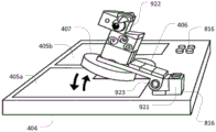
FIG. 7 illustrates another example of operation of an embodiment of a gaming system, such as the gaming system of one of FIGS. 4-6. In particular, fig. 7 shows a reader 404. Although not explicitly shown in fig. 7, reader 404 may be connected to a computer as described in connection with one or more of the previous figures. The reader 404 is of the type described in connection with fig. 5, i.e. a reader for reading RFID identification elements, in which case the reader comprises three detection areas: a writable detection area 406, as described in connection with fig. 4, and two read-only detection areas 405a, b. Fig. 7 also shows a first toy 409 comprising a first identification element positioned on the detection area 405 b. In this example, the first toy resembles a tractor attached to an identification element 407 including an RFID circuit as described in connection with the previous figures. When a tractor is positioned on the detection area 405b, the computer may control the video game to allow the user to control the virtual character to use or otherwise interact with the virtual tractor. To this end, the information associating the identification element 407 with the virtual tractor may have been previously stored on the identification element during manufacture of the system, or the information may have been stored by the user, such as described in connection with fig. 1 or 6.
Fig. 7 shows a second toy 709 which includes a second RFID identification element 707 and which is also positioned on the detection area 405b, together with and beside the first toy. In this example, the second toy resembles a motor block attached to an identification element 707 as described in connection with the previous figures. When the tractor 409 is positioned on the detection area 405b with the engine block 709, the computer may control the video game to allow the user to control the virtual character to use or otherwise interact with an enhanced virtual tractor, for example, a tractor that is able to travel faster and/or a tractor that pulls heavier equipment than a tractor without the enhancement. To this end, the information associating the identification element 707 with the augmentation to the virtual tractor may have been previously stored on the identification element during manufacture of the system, or the information may have been stored by the user, such as described in connection with fig. 4-6. Thus, a virtual tractor corresponding to toy 409 may have different attributes depending on whether toy 409 is positioned within the detection area of the reader alone (or with other items not configured to modify the tractor) or with engine block toy 709. When a tractor 409 is placed within the detection zone 405b, the corresponding virtual tractor may also be represented in a different manner on the display of the computer depending on whether it is placed in the reading zone with or without the engine block. For example, a virtual tractor may be displayed with a smaller or larger engine. It should be appreciated that the engine block 709 may also be configured to affect other virtual toys, such as virtual cars, virtual planes, etc., depending on whether the engine block is disposed on the detection area with the toy associated with the virtual car, virtual plane, etc. Further, it should be understood that the engine block may be configured to not affect certain other virtual items, such as virtual characters, virtual trees, etc., even if the engine block is placed on the detection area with a physical toy associated with the virtual character, virtual tree, etc. Thus, a physical toy may be associated with an attachment or augmentation to a virtual object that associates itself with another physical toy. When physical toys and other physical toys are placed within the detection area of the reader, virtual objects associated with the other physical toys may be represented as having accessories or enhancements. It will be appreciated that in some embodiments, the accessory toy must be positioned within the same detection area as another toy in order for it to affect a virtual object associated with the other toy. In other embodiments, the accessory toy must be positioned within a different detection area than another toy in order for it to affect a virtual object associated with the other toy. Finally, in yet other alternative embodiments, the accessory toy may affect a virtual object associated with another toy whether the physical toy and the other toy are positioned in the same or different detection areas. The particular enhancement provided may depend on placement in the same or different detection zones.
Fig. 8 shows an example of the RFID reader 404. Although not explicitly shown in fig. 8, the reader 404 may be connected to the computer via a wired or wireless connection, as described in connection with one or more of the previous figures. The reader 404 is of the type described in connection with fig. 5, i.e. a reader comprising three detection areas: a writable detection area 406, as described in connection with fig. 4, and two read- only detection areas 405a, 405 b.
The detection zones are all located on the top surface of the housing of the reader 404, but are spaced apart from each other. In this example, the detection zones 405a and 405b are L-shaped and allow at least three identification elements to be positioned within each of the detection zones 405a and 405b, e.g., one identification element in each leg of the L and a third identification element in the region where the legs meet. The detection zone 406 is shaped and dimensioned to allow only a single identification element to be positioned within the detection zone 406 at a time. The top surface of the reader 406 includes two sets of connectors 816a, 816 b. In this example, the connectors are protrusions arranged in a regular two-dimensional grid and are configured to frictionally engage corresponding cavities on the bottom surface of another toy construction element. The connectors are disposed adjacent to the respective detection regions 405a and 405 b. So as to allow toy construction elements of the type described herein to be connected to the reader 404. Thus, a user may add decorative parts to the reader, or a user may attach a toy construction model including an identification element to the reader, such as described below in connection with fig. 9.
Fig. 9 shows the reader 404 of fig. 8 with a toy construction model 909 attached to a connector 816a alongside the detection region 405 a. The toy construction model 909 includes a first portion 921, and a second portion 922 connected to the first portion via a hinge 924. The first and second portions may be formed as a single component or from a plurality of toy construction elements. The second part comprises an identification element 407, such as the RFID identification element described in connection with fig. 4-6. Thus, when the first part 1 is fixedly attached to the top surface of the reader 404, the second part 922 comprising the identification element 407 may be pivoted about the hinge 923 such that the identification element 407 may be moved to an activated state proximate to the detection region 405a or to a deactivated state further removed from the detection region 405 a. Further, the identification element 407 comprises a coil antenna defining an axis axially protruding from the bottom surface of the disc-shaped identification element. Similarly, the detection region 405a has a reader antenna associated therewith that also defines an axial axis projecting normally from the detection region 405 a. In the activated state, the axes of the identification element 407 and the detection zone 405a are aligned with each other, whereas in the deactivated state they are not aligned. The reader is configured such that: when the second portion 922 is pivoted such that the identification element 407 is in the activated state, it can only detect the presence of the identification element 407 within the detection region 405 a. Thus, a computer connected to the reader 404 may be configured to control game play in response to whether the detection element 407 is currently in an activated state or in a deactivated state. Thus, the user may conveniently activate/deactivate the functionality of the game system by lowering the second portion of the toy onto or raising it away from the detection surface defining the detection region 405 a. It will be appreciated that other embodiments may include different mechanisms for moving the movable part of the toy relative to the fixed part which is detachably attached to the reader, in order to bring the identification element contained in the movable part into/out of a detectable state, i.e. such that the identification element may be selectively detected by the detection area of the reader or remain undetected. Examples of such movements include rotational, translational movements, e.g. along or towards/away from a contact surface of the reader, etc. It should also be understood that the second portion may have a default state. For example, the second portion may be spring loaded or otherwise held in a detectable state or a non-detectable state by default. Similarly, the movement of the movable part relative to the fixed part may be operated manually, or it may be operated by a driver device, for example an actuator or motor which may be driven by electrical energy or other suitable energy source. Activation or deactivation may be triggered by a sensor input, such as a user pressing a button, a detected environmental state, such as a light sensor, a microphone, a proximity sensor, and the like.
Figures 10A-B and 11A-C illustrate examples of physical toys that include more than one identification element. In particular, fig. 10A-B and 11A-C show a physical toy comprising a first part 1021 and a second part 1022 movably interconnected with each other, i.e. the toy is formed as a coherent structure, but such that their respective interconnected parts can move relative to each other. In this example, the movement includes pivoting the portions relative to each other about hinge 1023. However, other forms of relative movement may be provided, such as translational movement, rotation, and the like. Each of the first and second portions includes a respective identification element 407a and 407b, respectively, such as an RFID identification element of the type described in connection with fig. 4-6. The toy is configured such that portions thereof are movable relative to one another between a single detection state (such as shown in fig. 10B, 11A, and 11B) and a dual detection state (such as shown in fig. 10A and 11C). When in the single detection state, the two parts are oriented such that the toy can be placed on the detection area of the reader with only a single one of the identification elements within the detection area, i.e. such that only a single one of the identification elements is detectable within the detection area, while the other identification elements are out of range of the detection area and cannot be detected. When in the dual detection state, the two parts are oriented such that the toy can be placed on the detection surface of the reader with the two identification elements within the detection area, i.e. such that the two identification elements are detectable by the reader.
For example, the toy of fig. 10A-B resembles a bridge spanned between two posts; the base of each post is formed by one of the identification elements. The bridge can be brought into an open state, in which two posts can be placed on the contact surface, and into a closed state, in which only one of the posts can be rested on the contact surface at any time, while the base of the other post is directed upwards away from the contact surface.
The toy of fig. 11A-C resembles a shell with an identification element located on the outer surface of the shell. The shell can be brought into an open state, in which both identification elements can be placed on the contact surface, and the shell can be brought into a closed state, in which only one of the identification elements can be positioned on the contact surface at any time, while the base of the other is directed upwards away from the contact surface.
Thus, depending on how the parts are positioned relative to each other, the toy may be positioned on the reader with only one or two identification elements on the detection area, e.g. in the same detection area, or as shown in fig. 10A, each in a different detection area. Fig. 11A-C show the shell in three different states: fig. 11A shows such a shell with the identification element 407a pointing downwards and positioned on the detection area of the reader (not explicitly shown in fig. 11A-C). In this state, when the identification element 407a is positioned within the detection area of the reader, the other identification element 407b cannot be detected by the reader. Fig. 11B shows such a shell with the identification element 407B pointing downwards and positioned on the detection area of the reader. In this state, when the identification element 407b is positioned within the detection area of the reader, the identification element 407a cannot be detected by the reader. Fig. 11C shows such a shell with both identification elements 407a and 407b pointing downwards and positioned on the detection area of the reader. In this state, the two identification elements 407a and 407b can be detected simultaneously in the same or corresponding detection areas of the reader.
Similarly, fig. 10B shows such a bridge with the identification element 407a pointing downward and positioned on the detection area of the reader (not explicitly shown in fig. 10B). In this state, when the identification element 407a is positioned within the detection area of the reader, the identification element 407b cannot be detected by the reader. Fig. 10B shows a bridge in which two identification elements 407B are directed downwards and positioned on the respective detection areas of the reader and are simultaneously detectable by the respective detection areas of the reader, i.e. so that identification element 407a is positioned in detection area 405a and identification element 407B is positioned in detection area 405B.
Thus, in the examples of fig. 10A-B and 11A-C, the reader may detect one or both identification recognition elements and, thus, the current state of the corresponding toy, i.e. how the respective parts are arranged relative to each other. To this end, the identification elements 407a, 407b of the toy may comprise the same identifier or other information identifying the toy, for example identifying a shell or a bridge. Thus, in such embodiments, the reader may identify the toy and distinguish between a single detection state and a dual detection state. Alternatively, the identification elements of the toy may comprise different information, such as information identifying the toy and the corresponding identification element, allowing the reader to further distinguish which of the two identification elements is detected in the single detection state, e.g. in order to distinguish the states shown in fig. 11A and 13B. Accordingly, the computer may control game play in response to the detected state, e.g., allowing a virtual character to traverse a virtual bridge associated with the physical toy of fig. 10A-B, depending on whether the physical toy bridge is detected in its open or closed state. Similarly, the virtual shell may allow access to its contents or have other attributes depending on whether the physical shell of fig. 11A-C is detected in its open or closed state.
The reader may also be configured to detect which detection zone the or each identification element is placed in, and the computer may control game play in response to the determined detection zone(s). For example, each detection region may be associated with a respective region of a virtual world or other game space. When a toy is positioned within the detection area, a virtual character or virtual object may be positioned in an associated area of the virtual world or game space. In the example of fig. 10A, i.e., when a bridge or other object is positioned such that its identification elements are positioned in two different detection areas, the areas associated with the two detection areas may be connected in the game, for example, by a bridge or other pathway, so as to allow the virtual character to move between the areas along the bridge or other pathway. For example, a bridge or channel may provide a shortcut or channel that is not available to other avatars in the game.
As described above in connection with fig. 9, relative movement of portions of the toy may be performed by application of manual force, by a motor or other actuator. The toys of fig. 10A-B and 11A-C may be assembled for use with the toy construction elements described herein.
Although the above examples show toys having two identification elements, it should be understood that other examples of physical toys may include 3, 4, or even more identification elements.
In the following, examples of toys comprising sensors (e.g. user controllable inputs) and one or more identification elements to transmit information about the sensor inputs to the reader will be described.
In particular, figures 12A-C illustrate an example of a toy 1209 that includes push buttons. The toy may be formed as a stand-alone toy element, or it may be assembled from a plurality of toy construction elements, for example of the type described above. Toy 1209 includes a tubular member 1224, and button 1225 is slidably disposed within tubular member 1224. The end of the button facing the tubular member is spring loaded and it can be pushed towards the other end by finger pressure. The base of the button includes an identification element 1207, such as an RFID tag as described herein. When the toy 1209 is placed in the detection area of a reader, such as the reader described above in connection with fig. 4-6, with the button 1225 facing upward, the identification element 1207 is positioned at a distance from the detection area, the distance being defined by the axial length of the tubular member. Thus, the distance may be configured such that the identification element is not detected by the detection area unless it is pressed downwards by finger pressure applied directly to the button or by pressure applied by another toy building element (another toy building element attached to the button). To this end, the button may comprise a connector for attaching other toy construction elements described herein. Fig. 12A shows a perspective view of a toy with button 1225 in its undetectable state. Fig. 12B shows a cross-sectional view of a toy with button 1225 in an undetectable state, while fig. 12C shows a cross-sectional view of a toy with button 1225 in an activated and detectable state.
Fig. 13 illustrates another example of a toy 1309 that includes three buttons 1325A-C that each include an identification element that can be selectively placed into a detectable state by applying finger pressure to the corresponding button. The identification elements of the respective buttons may be configured to transmit the same information when detected by the reader, or they may be configured to each transmit different information. Thus, the reader may be configured to detect the presence of a toy in the detection area, and how many buttons are currently pressed. In some embodiments, the reader is even able to identify which respective buttons are currently pressed.
It should be understood that other embodiments of the toy may include other types of movable elements that may be selectively brought into a detectable state. Other toys may include an automatic mechanism that includes a sensor and an actuator configured to automatically bring an identification element into a detectable state in response to a sensor signal.
The identification element may also control the information sent to the reader in different ways in response to sensor input.
For example, an alternative example of a toy including push buttons may be implemented using two RFID identification circuits, each configured to transmit a respective ID, for example as schematically shown in fig. 14. The toy element 1409 of fig. 14 includes two ID circuits 1426a, 1426b that are electrically coupled to an antenna 1427 via a switch 1425. For example, each identification circuit may include an RFID chip. The switch is configured to selectively couple one of the ID circuits to the antenna 1427 while the other ID circuit is decoupled from the antenna. Thus, depending on the activation state of the switch, information from one ID circuit or the other is transmitted. It should be understood that alternative embodiments of the toy may include a different number of ID circuits that may be selectively coupled to the antenna. For example, one embodiment of the toy may include a single identification circuit that may be selectively coupled to or decoupled from the antenna. Other examples may include 3, 4, or even more identification circuits, such that no circuit or one of the circuits may be coupled to the antenna at a given time.
It will be appreciated that the coupling of the identification circuit may be performed by galvanic, inductive or capacitive coupling, or in a different suitable way. In yet another embodiment, the information transmitted by the toy may be controlled in different ways, such as by selectively shielding the antenna or otherwise changing the transmission characteristics of the antenna. Further alternatively, the identification circuit may comprise a memory, wherein the identification circuit is configured to send information stored in the memory to the reader. The identification circuit may also include a control circuit that receives a signal indicating the activation state of the selector or another form of sensor signal. The control circuit may then be configured to store information about the activation state or other sensor signal in the memory, thereby causing the identification circuit to transmit the stored information indicative of the activation state or other sensor signal to the reader. The toy may be configured such that the memory content may only be changed when the toy is located within the detection region. Alternatively, the toy may be configured such that the memory content may only be changed when the toy is not located within the detection area. In yet another alternative embodiment, the toy may be configured such that the memory content may be changed regardless of whether the toy is located within the detection region. Thus, a computer receiving input from the reader may control game play based on the detected activation state of the toy or other sensor signals.
In the example of fig. 13A-C, the toy includes push buttons. However, alternative embodiments may include other forms of user-controllable activator or selector, such as a rotary button. For example, turning the button may allow a user to selectively couple one of the plurality of ID circuits to the antenna, such as by rotating the contact member. Other embodiments may include other types of sensors, such as light sensors, vibration sensors, tilt sensors, and the like.
In the example of fig. 13A-C, as well as other embodiments, activation of the push button can only be detected when the button is pressed while the toy is within the detection zone. Still, other embodiments of the toy may include sensors configured to: detecting activation, measuring a parameter, or providing another form of sensor input when the toy is not in the detection zone; and when the toy is subsequently positioned within the detection area of the reader, information is sent about such vibrations, measurements, or other forms of sensor input. For example, the user may change the position of the selector switch while the user holds the toy in the user's hand before placing the toy on the detection area of the reader. Another example of a toy may include a vibration sensor that detects a degree of vibration, e.g., a degree to which a user shakes the toy, and stores the detected degree in memory so that information may be subsequently sent when the toy is again placed in a detection area of the reader.
Figures 15A-C illustrate another example of a toy including sensors. In the example of fig. 5A-C, the sensor is a user-controllable rotatable knob. The toy includes a circuit including an identification element that transmits information indicative of the angular position of the rotatable knob. In particular, fig. 5A schematically illustrates an electrical control circuit of the toy, fig. 5B illustrates an exploded view of the toy, and fig. 5C illustrates a 3D view of the assembled toy.
The toy, generally designated 1509, includes a housing formed by a base plate 1536 and a generally dome-shaped cover 1528. The dome-shaped cover 1528 includes a hole 1540 at the apex of the dome, and the knob 1525 extends through the hole 1540. In particular, a portion of the knob extends up outside of the bore 1540 such that the portion of the knob may rotate relative to the cover and about a central axis defined by the knob and dome-shaped cover. Knob 1525 includes a connector 1514 at its top surface that allows one or more toy construction elements to be attached to the knob, for example, to configure the knob using decorative components, or to provide a customized grip therefor. The knob 1525 also includes a radially outwardly extending indicator element 1542 that indicates the current angular position of the knob relative to the cover. To this end, different markings may be provided on the outer surface of the cover, such that the indicator points at different angular positions to the different markings.
The portion of the knob that extends inwardly into the bore 1540 is attached to the rotatable member 1529 such that when the knob is rotated, the rotatable member 1529 rotates about the central axis. For this, the rotatable member is rotatably supported on the base plate 1536. The rotatable member comprises an electrically conductive activation member 1530 that also rotates with the rotatable member 1529 and knob 1525. The activation member includes two spring-biased conductive terminals 1531 and 1532, respectively, each configured to follow a circular trajectory as the knob 1525 is rotated. The conductive activation member provides a conductive path that connects the terminals 1531 and 1532 to each other. The trajectories defined by the movement of the terminals 1531 and 1532 when the knob 1525 is rotated are concentric circles around the central axis. The radius of the circle defined by the traces of the terminals 1532 is greater than the corresponding radius of the traces of the terminals 1531.
The toy also includes an identification element in the form of a ring-shaped circuit board 1533 that is fixedly disposed on the substrate 1536 and within the cover 1528 such that the spring-biased terminals are in contact with the top surface of the circuit board 1533. The top surface of the circuit board includes an internal circular conductive path 1535 and a plurality of separate conductive path segments 1534. Each conductive path segment is formed in an arc such that they together define an outer circle, but wherein the respective path segments are electrically isolated from each other and from the inner circular conductive path 1535. The inner and outer circles are concentric and correspond to the circular traces of terminals 1531 and 1532, respectively. Thus, when the knob is turned, the internal terminal 1531 is always in electrical contact with the internal circular conductive path 1535, while the external terminal 1532 is in contact with one of the conductive path segments 1534 or with the portion of the insulating arc separating the two conductive path segments 1534. Accordingly, depending on the angular position of the knob, the activation member provides an electrically conductive path before one or more electrically conductive path segments 1534 and the internal circular electrically conductive path 1535. In the example of fig. 15A-C, the circuit board includes eight path segments 1534. However, it should be understood that other embodiments may include a different number of path segments.
The circuit board 1533 also accommodates the circuit shown in fig. 15A. The circuit includes a microcontroller unit 1538, an RFID identification circuit 1539 operatively coupled to the microcontroller unit, an RFID antenna 1527 operatively coupled to the RFID identification circuit 1539. The microcontroller unit 1538 includes a plurality of switch contacts connected to respective path segments 1534. The microcontroller unit also includes a baseline input connected to the internal circular conductive path 1535. Thus, depending on the angular position of knob 1525, one or none of the switch contacts of the microcontroller unit is connected to the baseline input of the microcontroller unit. The microcontroller unit is configured to cause the RFID identification circuit, when interrogated, to transmit data indicating which, if any, of the switch contact tips are connected to the baseline. Accordingly, the control circuit of fig. 15A responds with data indicating the current angular position of knob 1525 when interrogated by an RFID reader. For example, each angular position of the knob may be associated with a different ID.
When toy 1509 is placed in a detection area of a reader, such as the reader described above in connection with fig. 4-6, the reader may detect the current angular position of the knob, and may control the digital game in response to the detected angular position of knob 1525. Thus, knob 1525 is a user-controllable actuator whose position is detected by the toy and communicated to the reader.
The above various embodiments of the various aspects disclosed in this specification have been described.
For example, embodiments of toys having two or more identical identification elements (e.g., identification elements that transmit the same ID or other information, also referred to as tags) have been described. Examples of toys allow a user to adjust the physical appearance of the toy. The adjustment also allows the user to change the relative position and/or orientation of the identification elements with respect to each other. Thus, the same two (or more tags) may be placed in the toy so that they can be read by the reader in one (or more) detection zones, either one after the other or more than one at a time. Embodiments of the digital game executed by the gaming system may display different virtual items, or change the behavior of virtual items, depending on how many tags are read, and optionally whether different tags are on the same detection area. For example, a physical toy may resemble a shell, and if a tag is read, a virtual shell may be displayed with the shell closed. If both tags are read, the shell is opened. This may allow access to different digital content if the tag is read by different read regions.
In some embodiments of aspects described herein, the different detection regions of the reader each represent a different location in the game. If two identical tags connected to the same toy are placed on different detection areas, i.e. such that the toy spans the gap between the detection areas, the areas represented in the game are connected, for example via a line, bridge, rope or spiral. This function may also be implemented with two (or more) toys (similar or dissimilar) with the same tag, which are not connected but visually represent a connection point, which may be an elevator, a train station, a gate, a phone, etc.
In some embodiments, virtual counterparts of unconnected or connected toys with the same tag may become connected in a digital game if placed on the same detection area. For example, if two toys similar to a small creature are positioned on the detection area, a single creature with a new appearance and/or capability may appear in the digital game.
In some embodiments, a label may be provided that may operate as a button. In such embodiments, the tag(s) may be positioned near or even in contact with the detection device, but with the tag(s) outside of the detection range of the detection device. When a button or other activator is pushed/rotated, etc., the tag may come into detection range of the reader and cause the function of the digital game to be activated, for example by presenting different possibilities in the digital game. Selection may then be made by flipping the tag (the marking go). In some embodiments, the toy may have two or more identical tags, with different functions/representations activated in the game depending on how many tags are read. In some embodiments, the function/representation may also be implemented depending on which of a plurality of detection regions the tag is detected in.
Similarly, examples of toys having two or more unique identification elements (e.g., identification elements that transmit different IDs or other information) have been described. Here, the term "unique" means tags that can be distinguished from each other. In some embodiments, two (or more) unique tags may be placed in the toy so that the reader can read them in one (or more) detection zones, either one after the other or more than one at a time. Depending on which tags of the physical toy are read, optionally in what combination and whether different tags are in the same detection area, the digital game may then display virtual items that differ in appearance, or virtual items that behave or operate differently. The physical toy may include two distinguishable tags configured such that only one tag may be detected at a time. For example, the tags may be disposed on different sides of the toy, such as opposite sides. When tags of toys like items/vehicles/motors are placed in the detection area designated by the game system, these tags may cause the virtual in-game counterpart of the toy to be combined into one item/vehicle/motor or the like with new attributes. These toys may also resemble puzzles in shape, or be physically interlocked so their appearance indicates that they can be combined.
The embodiments of the method described herein may be implemented by means of hardware comprising several distinct elements, and/or by means of a suitably programmed microprocessor, at least in part.
In the claims enumerating several means, several of these means may be embodied by one and the same item of hardware, component or item of hardware. The mere fact that certain measures are recited in mutually different dependent claims or described in different embodiments does not indicate that a combination of these measures cannot be used to advantage.
It should be emphasized that the term "comprises/comprising" when used in this specification is taken to specify the presence of stated features, elements, steps or components, but does not preclude the presence or addition of one or more other features, elements, steps, components or groups thereof.
Claims (14)
1. A gaming system, comprising:
a data processing system configured to execute program instructions that allow a user to participate in a digital game;
a physical toy; and
a detection device configured to detect the presence of a toy within a detection area of the detection device;
wherein the physical toy comprises two or more identification elements that are detectable by the detection device when each identification element is positioned within the detection area, wherein the physical toy is a coherent structure, wherein the two or more identification elements are physically interconnected with the structure, wherein the physical toy is configured to allow a user to selectively position the physical toy while having only a user-selected subset of one or more of the identification elements within the detection area; and wherein the data processing system is configured to control the digital game in response to the detected subset of identification elements, an
Wherein the physical toy is a coherent toy structure comprising a first portion and a second portion movably interconnected to each other; wherein the first portion comprises a first identification element of the two or more identification elements and the second portion comprises a second identification element of the two or more identification elements; wherein the second part is capable of entering into a first position relative to the first part such that the second identification element is not within the detection area of the detection device when the first identification element is positioned within the detection area of the detection device; and wherein the second part is capable of being brought into a second position relative to the first part such that when the first identification element is positioned within the detection area of the detection device, the second identification element is also within the detection area of the detection device.
2. The gaming system of claim 1, wherein the detection device includes at least two detection zones, and the detection device is configured to detect the presence of an identification element within each of the detection zones and to detect in which detection zone an identification element is placed; and wherein the data processing system is configured to control the digital game in response to a subset of the detected identification elements and in response to whether the detected subset is detected within the same detection area or whether the corresponding identification elements of the detected subset are detected within different detection areas.
3. The game system of claim 1 or 2, wherein the physical toy is configured to send information to the detection device when the physical toy is positioned in a detection area of the detection device; wherein the physical toy comprises a sensor configured to detect an input, and wherein the physical toy is configured to change the transmitted information in response to the detected input; and wherein the data processing system is configured to receive a detection signal from the detection device indicative of information transmitted by the physical toy and to control the digital game in response to the received detection signal.
4. The game system of claim 1 or 2, wherein the physical toy is configured such that it can only be positioned, at least in one configuration, such that each time a proper subset of the identification elements are within the detection area.
5. A gaming system, comprising:
a data processing system configured to execute program instructions that allow a user to participate in a digital game;
a physical toy; and
a detection device configured to detect the presence of the toy within a detection area of the detection device;
wherein the physical toy is configured to transmit information to the detection device when the physical toy is positioned in a detection area of the detection device; wherein the physical toy comprises a rotatable knob for controllable configured to detect an input, and wherein the physical toy is configured to change the transmitted information in response to the detected input; and wherein the data processing system is configured to receive a detection signal from the detection device indicative of information transmitted by the physical toy and to control the digital game in response to the received detection signal; wherein the physical toy comprises a circuit comprising an identification element configured to transmit information indicative of an angular position of the rotatable knob.
6. The gaming system of any preceding claim, wherein the data processing system is configured to receive input signals from the detection device indicative of the presence of two or more identification elements in respective detection areas, and to control the digital game in response to whether the two or more identification elements are detected in the same detection area or in different detection areas.
7. A gaming system, comprising:
a data processing system configured to execute program instructions that allow a user to participate in a digital game;
two or more identification elements included in the same physical toy, the toy being a coherent structure having a first portion and a second portion that are movable relative to each other; and
a detection device comprising two or more detection areas and configured to detect the presence of at least one of said identification elements in each of said detection areas of said detection device;
wherein the same physical toy is configured such that its first and second parts are relatively movable between a single detection state and a double detection state, and when in the single detection state, the first and second parts are oriented such that the same physical toy can be placed on a detection area within which only one identification element is located, while the other identification element is not within the range of the detection area and cannot be detected; when in the dual detection state, the first portion and the second portion are oriented such that the same physical toy can be placed on a detection surface and both identification elements are within a detection area such that both identification elements can be detected by a reader; and is
Wherein the data processing system is configured to receive input signals from the detection device indicative of the presence of two or more identification elements in respective detection areas and to control the digital game in response to whether the two or more identification elements are detected in the same detection area or in different detection areas.
8. The gaming system of any preceding claim, wherein the detection device comprises two or more detection areas and is configured to detect the presence of one or more identification elements in each detection area of the detection device; wherein the digital game comprises a digital environment comprising two or more regions; wherein the area is capable of being explored by a user-controllable character; and wherein the data processing system is configured to control game play in a first one of the zones in response to detecting the one or more identification elements in the first one of the detection zones and to control game play in a second one of the zones in response to detecting the one or more identification elements in the second one of the detection zones.
9. A gaming system, comprising:
a data processing system configured to execute program instructions that allow a user to participate in a digital game;
one or more identification elements; and
a detection device comprising two or more detection areas and configured to detect the presence of the identification element in each detection area of the detection device;
wherein the digital game comprises a digital environment comprising two or more regions; wherein the area is capable of being explored by a user-controllable character; and wherein the data processing system is configured to control game play in a first one of the zones in response to detection of the one or more identification elements in the first one of the detection zones and to control game play in a second one of the zones in response to detection of the one or more identification elements in a second one of the detection zones,
wherein the detection device comprises two or more detection areas, each detection area being associated with a respective one of the areas of the digital environment; and wherein the data processing system is configured to control the digital game in response to detecting the respective identification element in two different detection areas so as to affect both areas, an
Wherein the data processing system is configured to open a passage between two different detection areas in response to detecting respective identification elements in the two areas so as to allow the avatar to move along the opened passage from one of the two areas to the other of the two areas.
10. The game system of claim 9, wherein the identification element is a toy construction element comprising one or more connectors configured to mechanically connect one or more other toy construction elements to the identification element so as to allow a user to construct a toy construction model.
11. The gaming system of claim 10; wherein the data processing system is configured to:
detecting the presence of the identification element within a detection zone;
establishing an association between a virtual object in the virtual environment and the detected identification element;
accessing information associated with the identification element when the identification element is again placed within a detection area;
presenting a representation of the associated virtual object based on the accessed information; and
executing a game mode program including controlling a representation of the virtual object.
12. The gaming system of claim 11, wherein the data processing system is configured to replace an existing association between a new virtual object and the identification element with a new association between the identification element and the virtual object in response to a game event, such that when the data processing system again detects the presence of the identification element, the data processing system renders a representation of the new virtual object and executes a game mode program that includes controlling the representation of the new virtual object.
13. The gaming system of any of claims 11 to 12, wherein the data processing system is configured to replace an existing association with a new association of a new virtual object with the identification element in response to a game event so as to allow a user to construct different toy construction models using the identification element, each toy construction model having a respective virtual object associated therewith.
14. A gaming system as claimed in claim 11 or 12, wherein the gaming system comprises a plurality of toy construction elements, and wherein the data processing system is configured to present a graphical representation of a virtual object, the graphical representation resembling a toy construction model that can be constructed from the plurality of toy construction elements.
Priority Applications (1)
| Application Number | Priority Date | Filing Date | Title |
|---|---|---|---|
| CN202110947508.2A CN113952732A (en) | 2015-04-08 | 2016-04-07 | Game system |
Applications Claiming Priority (3)
| Application Number | Priority Date | Filing Date | Title |
|---|---|---|---|
| DKPA201570204 | 2015-04-08 | ||
| DKPA201570204 | 2015-04-08 | ||
| PCT/EP2016/057592 WO2016162403A1 (en) | 2015-04-08 | 2016-04-07 | Game system |
Related Child Applications (1)
| Application Number | Title | Priority Date | Filing Date |
|---|---|---|---|
| CN202110947508.2A Division CN113952732A (en) | 2015-04-08 | 2016-04-07 | Game system |
Publications (2)
| Publication Number | Publication Date |
|---|---|
| CN107708823A CN107708823A (en) | 2018-02-16 |
| CN107708823B true CN107708823B (en) | 2021-08-31 |
Family
ID=55699635
Family Applications (2)
| Application Number | Title | Priority Date | Filing Date |
|---|---|---|---|
| CN201680033735.1A Active CN107708823B (en) | 2015-04-08 | 2016-04-07 | Game system |
| CN202110947508.2A Pending CN113952732A (en) | 2015-04-08 | 2016-04-07 | Game system |
Family Applications After (1)
| Application Number | Title | Priority Date | Filing Date |
|---|---|---|---|
| CN202110947508.2A Pending CN113952732A (en) | 2015-04-08 | 2016-04-07 | Game system |
Country Status (6)
| Country | Link |
|---|---|
| US (2) | US10799802B2 (en) |
| EP (1) | EP3280504A1 (en) |
| JP (2) | JP6974173B2 (en) |
| KR (2) | KR102513852B1 (en) |
| CN (2) | CN107708823B (en) |
| WO (1) | WO2016162403A1 (en) |
Families Citing this family (15)
| Publication number | Priority date | Publication date | Assignee | Title |
|---|---|---|---|---|
| US10835810B2 (en) * | 2015-10-21 | 2020-11-17 | Activision Publishing, Inc. | Interactive videogame using a physical object with touchpoints |
| IL250429A0 (en) * | 2017-02-02 | 2017-03-30 | Jug Tech Ltd | Motion sensing device with interchangeable designed elements and method for using the same |
| EP3593406B1 (en) * | 2017-03-06 | 2023-11-01 | Suffuse Inc. | Interactive digital platform device and method |
| CN107008018B (en) * | 2017-04-28 | 2021-09-14 | 广东乐博士教育装备有限公司 | Building blocks picture arragement assembly structure and building blocks toy |
| EP3697511A1 (en) * | 2017-10-16 | 2020-08-26 | Lego A/S | Interactive play apparatus |
| WO2019111604A1 (en) * | 2017-12-08 | 2019-06-13 | ソニー株式会社 | First information processing apparatus, second information processing apparatus, information processing method, program, and information processing system |
| EP3727623B1 (en) | 2017-12-19 | 2022-05-04 | Lego A/S | Play system and method for detecting toys |
| US11311250B2 (en) * | 2017-12-26 | 2022-04-26 | Amrita Vishwa Vidyapeetham | Spectroscopic monitoring for the measurement of multiple physiological parameters |
| USD844394S1 (en) | 2018-03-29 | 2019-04-02 | Kraft Foods Group Brands Llc | Mold |
| US10894342B2 (en) | 2018-03-29 | 2021-01-19 | Kraft Foods Group Brands Llc | System and method for molding comestible building blocks |
| CN110975281A (en) * | 2019-11-12 | 2020-04-10 | 武汉金运激光股份有限公司 | Game interaction method and system based on NFC chip |
| US20210248285A1 (en) * | 2020-02-07 | 2021-08-12 | John Herbert Orsos Barrenechea | Application software to teach how to build a stock car racing |
| CN113521754B (en) * | 2021-08-04 | 2024-02-27 | 广州四三九九信息科技有限公司 | Method for preventing conflict of configuration of multiple persons in data processing of map editor |
| IT202100025214A1 (en) * | 2021-10-01 | 2023-04-01 | Stress | COMPUTERIZED BUILDING ELEMENT |
| WO2023212176A1 (en) * | 2022-04-27 | 2023-11-02 | Modern Games, Inc. | Systems and methods for physical blocks and corresponding virtual game elements |
Citations (4)
| Publication number | Priority date | Publication date | Assignee | Title |
|---|---|---|---|---|
| CN1342275A (en) * | 1999-02-01 | 2002-03-27 | 英特莱格公司 | Interactive entertainment systems and methods |
| JP3927921B2 (en) * | 2003-05-19 | 2007-06-13 | 株式会社バンダイナムコゲームス | PROGRAM, INFORMATION STORAGE MEDIUM, AND GAME DEVICE |
| US20140179446A1 (en) * | 2012-12-20 | 2014-06-26 | Leo Zuniga | Interactive video game with toys having interchangeable parts |
| US20140274412A1 (en) * | 2013-03-15 | 2014-09-18 | Digital Dream Labs, Llc | System and Method for Using Interconnecting Blocks as Input and Output for Electronic Devices |
Family Cites Families (18)
| Publication number | Priority date | Publication date | Assignee | Title |
|---|---|---|---|---|
| US3005282A (en) | 1958-01-28 | 1961-10-24 | Interlego Ag | Toy building brick |
| TW393334B (en) * | 1998-10-14 | 2000-06-11 | Interlego Ag | Toy building set |
| US6443796B1 (en) * | 2000-06-19 | 2002-09-03 | Judith Ann Shackelford | Smart blocks |
| JP2002000938A (en) | 2000-06-20 | 2002-01-08 | Tomy Co Ltd | Game system information rewrite device and storage medium |
| JP4565096B2 (en) * | 2001-03-14 | 2010-10-20 | 新世代株式会社 | Identification method, identification device, input device, and recording medium for identifying an object to be identified without contact |
| JP4025685B2 (en) * | 2003-05-23 | 2007-12-26 | 株式会社バンダイナムコゲームス | PROGRAM, INFORMATION STORAGE MEDIUM, AND GAME DEVICE |
| JP2006116122A (en) | 2004-10-22 | 2006-05-11 | Tomy Co Ltd | Magnetic display device |
| JP2007072719A (en) * | 2005-09-06 | 2007-03-22 | Nec Corp | Story output system, robot device and story output method |
| US20130288563A1 (en) * | 2005-10-21 | 2013-10-31 | Patent Category Corporation | Interactive toy system |
| US7843471B2 (en) * | 2006-03-09 | 2010-11-30 | International Business Machines Corporation | Persistent authenticating mechanism to map real world object presence into virtual world object awareness |
| US8257157B2 (en) * | 2008-02-04 | 2012-09-04 | Polchin George C | Physical data building blocks system for video game interaction |
| US10155156B2 (en) | 2008-06-03 | 2018-12-18 | Tweedletech, Llc | Multi-dimensional game comprising interactive physical and virtual components |
| CN201668949U (en) * | 2010-01-12 | 2010-12-15 | 王青方 | Electronic game system and device utilizing radio-frequency identification technology |
| US9381430B2 (en) | 2011-05-17 | 2016-07-05 | Activision Publishing, Inc. | Interactive video game using game-related physical objects for conducting gameplay |
| JP5474919B2 (en) * | 2011-12-06 | 2014-04-16 | 株式会社コナミデジタルエンタテインメント | GAME SYSTEM, GAME SYSTEM CONTROL METHOD, AND PROGRAM |
| WO2013183328A1 (en) | 2012-06-05 | 2013-12-12 | ソニー株式会社 | Information processing device, information processing method, program and toy system |
| US9575156B2 (en) | 2013-01-15 | 2017-02-21 | Disney Enterprises, Inc. | Spatial recognition of RFID tag placement using antenna multiplexing |
| US9011194B2 (en) | 2013-03-15 | 2015-04-21 | Disney Enterprises, Inc. | Managing virtual content based on information associated with toy objects |
-
2016
- 2016-04-07 KR KR1020177031946A patent/KR102513852B1/en active IP Right Grant
- 2016-04-07 KR KR1020237009642A patent/KR102593302B1/en active IP Right Grant
- 2016-04-07 EP EP16715290.9A patent/EP3280504A1/en active Pending
- 2016-04-07 JP JP2017552913A patent/JP6974173B2/en active Active
- 2016-04-07 CN CN201680033735.1A patent/CN107708823B/en active Active
- 2016-04-07 CN CN202110947508.2A patent/CN113952732A/en active Pending
- 2016-04-07 US US15/563,832 patent/US10799802B2/en active Active
- 2016-04-07 WO PCT/EP2016/057592 patent/WO2016162403A1/en active Application Filing
-
2020
- 2020-02-12 US US16/789,177 patent/US10881970B2/en active Active
-
2021
- 2021-11-01 JP JP2021178677A patent/JP7273926B2/en active Active
Patent Citations (4)
| Publication number | Priority date | Publication date | Assignee | Title |
|---|---|---|---|---|
| CN1342275A (en) * | 1999-02-01 | 2002-03-27 | 英特莱格公司 | Interactive entertainment systems and methods |
| JP3927921B2 (en) * | 2003-05-19 | 2007-06-13 | 株式会社バンダイナムコゲームス | PROGRAM, INFORMATION STORAGE MEDIUM, AND GAME DEVICE |
| US20140179446A1 (en) * | 2012-12-20 | 2014-06-26 | Leo Zuniga | Interactive video game with toys having interchangeable parts |
| US20140274412A1 (en) * | 2013-03-15 | 2014-09-18 | Digital Dream Labs, Llc | System and Method for Using Interconnecting Blocks as Input and Output for Electronic Devices |
Also Published As
| Publication number | Publication date |
|---|---|
| JP7273926B2 (en) | 2023-05-15 |
| EP3280504A1 (en) | 2018-02-14 |
| US10881970B2 (en) | 2021-01-05 |
| JP2022009815A (en) | 2022-01-14 |
| CN113952732A (en) | 2022-01-21 |
| US20200179815A1 (en) | 2020-06-11 |
| CN107708823A (en) | 2018-02-16 |
| US20180078863A1 (en) | 2018-03-22 |
| KR102593302B1 (en) | 2023-10-25 |
| KR20170134644A (en) | 2017-12-06 |
| US10799802B2 (en) | 2020-10-13 |
| JP6974173B2 (en) | 2021-12-01 |
| KR20230044322A (en) | 2023-04-03 |
| JP2018516109A (en) | 2018-06-21 |
| KR102513852B1 (en) | 2023-03-27 |
| WO2016162403A1 (en) | 2016-10-13 |
Similar Documents
| Publication | Publication Date | Title |
|---|---|---|
| CN107708823B (en) | Game system | |
| EP3200886B1 (en) | Game system | |
| US11014014B2 (en) | Toy construction system for augmented reality | |
| KR102156537B1 (en) | Information processing apparatus, information processing method, and information medium | |
| EP3160606B1 (en) | Interactive play sets | |
| US20090005167A1 (en) | Mobile Gaming with External Devices in Single and Multiplayer Games | |
| EP3593406B1 (en) | Interactive digital platform device and method | |
| US20180071626A1 (en) | Tag reader and system comprising a tag reader | |
| WO2007045944A1 (en) | Interoperation between virtual gaming environment and real-world environments | |
| CN116056771A (en) | User configurable interactive toy | |
| US20230338865A1 (en) | User configurable interactive toy |
Legal Events
| Date | Code | Title | Description |
|---|---|---|---|
| PB01 | Publication | ||
| PB01 | Publication | ||
| SE01 | Entry into force of request for substantive examination | ||
| SE01 | Entry into force of request for substantive examination | ||
| GR01 | Patent grant | ||
| GR01 | Patent grant |