CN107664012B - Turbine type bidirectional high-frequency composite impactor - Google Patents
Turbine type bidirectional high-frequency composite impactor Download PDFInfo
- Publication number
- CN107664012B CN107664012B CN201711085649.8A CN201711085649A CN107664012B CN 107664012 B CN107664012 B CN 107664012B CN 201711085649 A CN201711085649 A CN 201711085649A CN 107664012 B CN107664012 B CN 107664012B
- Authority
- CN
- China
- Prior art keywords
- turbine
- impact
- body cylinder
- hammer
- liquid inlet
- Prior art date
- Legal status (The legal status is an assumption and is not a legal conclusion. Google has not performed a legal analysis and makes no representation as to the accuracy of the status listed.)
- Active
Links
Images


Classifications
-
- E—FIXED CONSTRUCTIONS
- E21—EARTH DRILLING; MINING
- E21B—EARTH DRILLING, e.g. DEEP DRILLING; OBTAINING OIL, GAS, WATER, SOLUBLE OR MELTABLE MATERIALS OR A SLURRY OF MINERALS FROM WELLS
- E21B4/00—Drives for drilling, used in the borehole
- E21B4/06—Down-hole impacting means, e.g. hammers
- E21B4/14—Fluid operated hammers
-
- Y—GENERAL TAGGING OF NEW TECHNOLOGICAL DEVELOPMENTS; GENERAL TAGGING OF CROSS-SECTIONAL TECHNOLOGIES SPANNING OVER SEVERAL SECTIONS OF THE IPC; TECHNICAL SUBJECTS COVERED BY FORMER USPC CROSS-REFERENCE ART COLLECTIONS [XRACs] AND DIGESTS
- Y02—TECHNOLOGIES OR APPLICATIONS FOR MITIGATION OR ADAPTATION AGAINST CLIMATE CHANGE
- Y02E—REDUCTION OF GREENHOUSE GAS [GHG] EMISSIONS, RELATED TO ENERGY GENERATION, TRANSMISSION OR DISTRIBUTION
- Y02E10/00—Energy generation through renewable energy sources
- Y02E10/20—Hydro energy
Landscapes
- Engineering & Computer Science (AREA)
- Life Sciences & Earth Sciences (AREA)
- Geology (AREA)
- Mining & Mineral Resources (AREA)
- Mechanical Engineering (AREA)
- Physics & Mathematics (AREA)
- Environmental & Geological Engineering (AREA)
- Fluid Mechanics (AREA)
- General Life Sciences & Earth Sciences (AREA)
- Geochemistry & Mineralogy (AREA)
- Earth Drilling (AREA)
Abstract
The invention provides a turbine type bidirectional high-frequency composite impactor, which consists of a turbine assembly, an impact assembly and an adapter. The front end of the turbine assembly is connected with the adapter, the front end of the adapter is connected with the impact assembly, hydraulic energy is converted into mechanical energy for rotating a turbine shaft through the turbine assembly, so that a rotary valve of the impact assembly is driven to rotate, drilling fluid periodically enters a hammer head and a hammer body cylinder cavity due to the fact that holes are formed in the rotary valve and a valve cover, the hammer head periodically impacts the hammer body cylinder to generate circumferential shock under the pushing of the fluid, meanwhile, the axial holes of the rotary valve and the valve cover periodically misplacement to enable the fluid pressure to change, high-frequency axial shock is generated, axial impact force and circumferential impact force are transmitted to a drill bit through the lower connector, stick-slip phenomenon is eliminated, the drill bit is protected, and accordingly rock breaking efficiency of the drill bit is improved. The turbine type bidirectional high-frequency composite impactor disclosed by the invention utilizes drilling fluid to generate axial and circumferential impacts, and can effectively improve the drilling efficiency.
Description
Technical Field
The invention relates to a downhole tool for petroleum drilling, in particular to a turbine type bidirectional high-frequency composite impactor.
Background
In conventional petroleum drilling, PDC drill bits are widely used, and in field operation, drilling speed is often affected due to unstable drilling pressure applied to the drill bit, influence on rock breaking efficiency, and even damage to the drill bit, cutting teeth of a broken drill bit and the like caused by sudden increase of drilling pressure due to untimely drilling or too fast drilling caused by driller technology and experience problems or due to friction resistance of a well wall. On the other hand, PDC bits often do not have enough torque to break rock when drilling hard or abrasive formations, thereby creating a stuck bit, and release of torque from the drill rod downhole results in bit failure. The rock of the deep stratum of the oil field is hard and has high grinding extremum, the conventional roller bit is used for drilling, the single bit has small footage, multiple tripping is needed, and the mechanical drilling speed is low; when the screw is used for compound drilling, the service life of the screw is low and the use effect is not ideal due to higher temperature in a deep well; in addition, the mechanical drilling speed can be improved to a greater extent by adopting the gas drilling technology, but the underground complex situation is easy to occur under the condition of stratum water outlet, and the gas drilling supporting equipment is more, so that the cost is relatively high.
Aiming at the problems, various tools are tried at home and abroad, and a certain accelerating effect is achieved, wherein the high-frequency torsional impact type tools take the dominant role of the accelerating tools. The tool can add high-frequency torsional impact force to the drill bit to assist the drill bit in breaking rock, reduce the stick-slip phenomenon of the drill string and improve the mechanical drilling speed. In recent years, axial impact type speed-increasing tools are also emerging, and the tools can greatly improve the rock penetration depth of a drill bit, increase the rock breaking efficiency and have the characteristics of simplicity in operation, good speed-increasing effect and the like. Therefore, it is necessary to develop a power which can be provided by drilling fluid, and a composite double-acting impactor which can provide axial impact and circumferential impact, and has the advantages of assisting the rock breaking of the drill bit, protecting the drill bit, prolonging the service life of the drill bit and improving the drilling speed.
Disclosure of Invention
In order to solve the stick-slip phenomenon of the drill bit stuck and the drill string in the drilling process, a turbine type bidirectional high-frequency composite impactor is provided, so that the defects of the prior art are overcome, and the drilling speed is improved. The tool has axial impact and circumferential impact at the same time, can effectively protect a drill bit, reduce cost, improve rock breaking efficiency and increase drilling efficiency.
The technical scheme of the invention is as follows: the turbine type bidirectional high-frequency composite impactor consists of a turbine assembly, an impact assembly and an adapter, wherein the front end of the turbine assembly is connected with the adapter; the turbine assembly comprises a turbine body, an angular contact ball bearing, an anti-drop ring a, a limit sleeve a, a turbine stator, a turbine rotor, a transmission key, a limit sleeve b, a rectangular sealing ring, a turbine shaft, a cylindrical roller bearing, a thrust ball bearing and the anti-drop ring b, wherein the turbine rotor, the turbine stator and the limit sleeve b are sequentially arranged on the turbine shaft through the transmission key, the anti-drop ring a is arranged on the upper part of the turbine shaft, the two angular contact ball bearings are reversely arranged on the turbine body and the upper part of the turbine shaft, the limit sleeve a and the rectangular sealing ring are arranged on the turbine body in advance, the turbine stator is placed in the turbine body through spline fit, the cylindrical roller bearing, the thrust ball bearing and the limit ring are sequentially arranged on the front step of the turbine shaft from top to bottom, and the front end of the turbine shaft is in threaded connection with the transmission shaft; the rear end of the adapter is connected with the turbine body, and the front end of the adapter is connected with the short joint; the impact assembly comprises a sleeve, a rotary valve, a valve cover, a hammer head, a hammer body cylinder, an impact shell, a locking cylinder and a lower joint, wherein the rear end of the rotary valve is fixed at the front end of a transmission shaft through threads; the turbine rotor of the turbine assembly converts the energy of the liquid into the mechanical energy of rotation, so that the rotary valve of the impact assembly is driven to rotate, and because holes are formed in the rotary valve and the valve cover, drilling fluid periodically enters the hammer head and the hammer body cylinder cavity, the hammer head periodically impacts the hammer body cylinder to generate circumferential shock under the pushing of the liquid, meanwhile, the axial holes of the rotary valve and the valve cover periodically misplacement to enable the liquid pressure to change, high-frequency axial vibration is generated, and the axial impact force and the circumferential impact force are transmitted to the drill bit through the lower joint, so that the stick-slip phenomenon is eliminated, and the rock breaking efficiency is improved.
The turbine type bidirectional high-frequency composite impactor is characterized in that: the rotary valve is driven by the turbine assembly to rotate, and the liquid pressure is periodically changed under the action of the valve cover to generate axial vibration impact; the valve cover is provided with 4 fan-shaped liquid inlet holes, wherein the fan-shaped liquid inlet holes comprise two impact liquid inlet holes and two return liquid inlet holes, liquid periodically enters the impact liquid inlet holes and the return liquid inlet holes through rotation of the rotary valve, enters cavities of the hammer head and the hammer body cylinder through the liquid inlet holes, rotates at a notch of the hammer body cylinder by utilizing hydraulic pressure to push the hammer head, liquid enters the push hammer head from the impact liquid inlet holes to impact the hammer body cylinder in the circumferential forward direction, liquid enters the push hammer head from the return liquid inlet holes to return in the circumferential reverse direction, the cross section area of the impact liquid inlet holes is larger than the area of the return liquid inlet holes, and single circumferential impact can be realized.
According to the turbine type bidirectional high-frequency composite impactor, the hammer body barrel is provided with the two step notches which are uniformly distributed at the impact end, and the front end is provided with the internal thread for being matched with the external thread of the locking barrel.
The beneficial effects of the invention are as follows: (1) The difficult problem of blockage or clamping caused by a downhole drilling tool in the drilling process is solved; (2) The turbine assembly of the tool does not generate axial pressure, and has high energy conversion efficiency and short axial dimension; (3) The tool has reasonable design and reliable performance, can generate axial vibration impact while generating circumferential impact, thereby effectively protecting the drill bit, eliminating the stick-slip and drill sticking phenomena of the drill bit and improving the mechanical drilling speed; (4) The tool has strong adaptability, not only can be applied to deep vertical wells, but also can be applied to directional wells and horizontal wells by being matched with a screw drilling tool and a directional instrument; (5) The tool has the advantages of no dead point in action, large forward impact force in the circumferential direction, small reverse impact force and the like; (6) The mechanical drilling speed of the deep well hard stratum can be effectively improved by being matched with the PDC drill bit.
Drawings
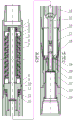
Fig. 1 is a schematic structural view of the present invention.
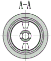
FIG. 2 is a cross-sectional view A-A of FIG. 1 in accordance with the present invention.
FIG. 3 is a sectional view B-B of FIG. 1 according to the present invention.
FIG. 4 is a cross-sectional view of the C-C of FIG. 1 in accordance with the present invention.
Fig. 5 is a schematic diagram of a rotary valve structure.
Fig. 6 is a schematic view of a valve cover structure.
Fig. 7 is a three-dimensional schematic of a hammer head structure.
Fig. 8 is a schematic view of the hammer barrel structure.
Fig. 9 is a three-dimensional schematic view of the lower joint structure.
The turbine engine comprises a turbine body 1, an angular contact ball bearing 3, an anti-drop ring a,4, a limit sleeve a,5, a turbine stator, 6, a turbine rotor, 7, a drive key, 8, a limit sleeve b,9, a rectangular sealing ring, 10, a turbine shaft, 11, a cylindrical roller bearing 12, a thrust ball bearing 13, an anti-drop ring b,14, a conversion joint 15, a transmission shaft 16, a short joint 17, a sleeve 18, a rotary valve 19, a valve cover 20, a hammer head 21, a hammer body cylinder 22, an impact shell 23, a locking cylinder 24 and a lower joint.
Detailed Description
The present invention will be described in detail with reference to the accompanying drawings and examples.
Referring to the drawings, the turbine type bidirectional high-frequency composite impactor consists of a turbine assembly, an impact assembly and an adapter (14), wherein the front end of the turbine assembly is connected with the adapter 14, and the front end of the adapter 14 is connected with the impact assembly; the turbine assembly comprises a turbine body 1, an angular contact ball bearing 2, a drop-proof ring a3, a limit sleeve a4, a turbine stator 5, a turbine rotor 6, a transmission key 7, a limit sleeve b8, a rectangular sealing ring 9, a turbine shaft 10, a cylindrical roller bearing 11, a thrust ball bearing 12 and a drop-proof ring b13, wherein the turbine rotor 6, the turbine stator 5 and the limit sleeve b8 are sequentially arranged on the turbine shaft 10 through the transmission key 7, the drop-proof ring a3 is arranged on the upper part of the turbine shaft 10, the two angular contact ball bearings 2 are reversely arranged on the turbine body 1 and the upper part of the turbine shaft 10, the limit sleeve a4 and the rectangular sealing ring 9 are arranged on the turbine body 1 in advance, the turbine stator 5 is placed in the turbine body 1 through spline fit, the cylindrical roller bearing 11, the thrust ball bearing 12 and the limit ring 13 are sequentially arranged on the front step of the turbine shaft 10 from top to bottom, and the front end of the turbine shaft 10 is in threaded connection with a transmission shaft 15; the rear end of the adapter 14 is connected with the turbine body 1, and the front end is connected with the short joint 16.
The impact assembly consists of a sleeve 17, a rotary valve 18, a valve cover 19, a hammer head 20, a hammer body cylinder 21, an impact shell 22, a locking cylinder 23 and a lower joint 24, wherein the rear end of the rotary valve 18 is fixed at the front end of a transmission shaft 15 through threads, the valve cover 19 is arranged on the end face of the hammer body cylinder 21, the hammer head 20 is arranged between the valve cover 21 and the hammer body cylinder 21, the hammer body cylinder 21 is arranged in the impact shell 22, the lower joint 24 is axially fixed on the impact shell 22 through the threaded connection of the locking cylinder 23 and the hammer body cylinder 21, the hammer body cylinder 21 and the impact shell 22 are circumferentially fixed with the lower joint 24 in a jaw manner, and the sleeve 17 is arranged between the conversion joint 14 and the hammer body cylinder 21; the turbine rotor 6 of the turbine assembly converts the energy of the liquid into the mechanical energy of rotation, so that the rotary valve 18 of the impact assembly is driven to rotate, the drilling fluid periodically enters the cavities of the hammer head 20 and the hammer body cylinder 21 due to the fact that holes are formed in the rotary valve 18 and the valve cover 19, the hammer head 20 periodically impacts the hammer body cylinder to generate circumferential shock under the pushing of the liquid, meanwhile, the axial holes of the rotary valve 18 and the valve cover 19 periodically misplacement to enable the pressure of the liquid to change, high-frequency axial shock is generated, and axial and circumferential impact forces are transmitted to the drill bit through the lower joint 24, so that the stick-slip phenomenon is eliminated, and the rock breaking efficiency is improved.
The front end disc surface of the rotary valve 18 is provided with two symmetrical sector holes, the circumference of the rear end cylinder is provided with two symmetrical round holes, the rotary valve 18 is driven by the turbine assembly to rotate, and the liquid pressure is periodically changed under the action of the valve cover 19 to generate axial vibration impact; the valve cover 19 is provided with 4 fan-shaped liquid inlet holes, wherein the fan-shaped liquid inlet holes comprise two impact liquid inlet holes and two return liquid inlet holes, the rotary valve 18 rotates to enable liquid to periodically enter the impact liquid inlet holes and the return liquid inlet holes, the liquid enters the cavities of the hammer head 20 and the hammer body cylinder 21 through the liquid inlet holes, the hydraulic pressure is utilized to push the hammer head 20 to rotate at a notch of the hammer body cylinder 21, the liquid enters the push hammer head 20 from the impact liquid inlet holes to impact the hammer body cylinder 21 in the positive direction in the circumferential direction, the liquid enters the push hammer head 20 from the return liquid inlet holes in the reverse direction in the circumferential direction, the cross section area of the impact liquid inlet holes is larger than the area of the return liquid inlet holes, and single circumferential impact can be realized.
The impact end of the hammer body cylinder 21 is provided with two step notches which are uniformly distributed, and the front end of the hammer body cylinder is provided with internal threads which are used for being matched with external threads of the locking cylinder 23.
Claims (4)
1. The turbine type bidirectional high-frequency composite impactor is characterized in that: the turbine type bidirectional high-frequency composite impactor consists of a turbine assembly, an impact assembly and an adapter (14), wherein the front end of the turbine assembly is connected with the adapter (14), and the front end of the adapter (14) is connected with the impact assembly; the turbine assembly comprises a turbine body (1), an angular contact ball bearing (2), a drop-proof ring a (3), a limit sleeve a (4), a turbine stator (5), a turbine rotor (6), a transmission key (7), a limit sleeve b (8), a rectangular sealing ring (9), a turbine shaft (10), a cylindrical roller bearing (11), a thrust ball bearing (12) and a drop-proof ring b (13), wherein the turbine rotor (6), the turbine stator (5) and the limit sleeve b (8) are sequentially arranged on the turbine shaft (10) through the transmission key (7), the drop-proof ring a (3) is arranged on the upper part of the turbine shaft (10), the two angular contact ball bearings (2) are reversely arranged on the upper parts of the turbine body (1) and the turbine shaft (10), the limit sleeve a (4) and the rectangular sealing ring (9) are arranged on the turbine body (1) in advance, the turbine stator (5) is placed in the turbine body (1) through spline fit, the cylindrical roller bearing (11), the thrust ball bearing (12) and the limit sleeve b (13) are sequentially arranged on the front of the turbine shaft (10) from top to bottom, and the front end of the turbine shaft (10) is connected with a transmission shaft (15); the rear end of the adapter (14) is connected with the turbine body (1), and the front end is connected with the short joint (16); the impact assembly comprises a sleeve (17), a rotary valve (18), a valve cover (19), a hammer head (20), a hammer body cylinder (21), an impact shell (22), a locking cylinder (23) and a lower joint (24), wherein the rear end of the rotary valve (18) is fixed at the front end of a transmission shaft (15) through threads, the valve cover (19) is arranged on the end face of the hammer body cylinder (21), the hammer head (20) is arranged between the valve cover (21) and the hammer body cylinder (21), the hammer body cylinder (21) is arranged in the impact shell (22), the lower joint (24) is axially fixed on the impact shell (22) through the threaded connection of the locking cylinder (23) and the hammer body cylinder (21), the hammer body cylinder (21) and the impact shell (22) are circumferentially fixed with the lower joint (24) through a jaw mode, and the sleeve (17) is arranged between the conversion joint (14) and the hammer body cylinder (21); the turbine rotor (6) of the turbine assembly converts the energy of the liquid into the mechanical energy of rotation, so that the rotary valve (18) of the impact assembly is driven to rotate, as holes are formed in the rotary valve (18) and the valve cover (19), the drilling fluid periodically enters the hammer head (20) and the hammer body cylinder (21) cavity, the hammer head (20) periodically impacts the hammer body cylinder to generate circumferential shock under the pushing of the liquid, and meanwhile, the axial holes of the rotary valve (18) and the valve cover (19) periodically misplacement to change the pressure of the liquid to generate high-frequency axial shock, and the axial and circumferential impact force is transmitted to the drill bit through the lower joint (24), so that the stick-slip phenomenon is eliminated, and the rock breaking efficiency is improved.
2. The turbine type bidirectional high frequency composite impactor of claim 1, wherein: the front end disc surface of the rotary valve (18) is provided with two symmetrical sector holes, the circumference of the rear end cylinder is provided with two symmetrical round holes, the rotary valve (18) is driven by the turbine assembly to rotate, and the liquid pressure is periodically changed under the action of the valve cover (19) to generate axial vibration impact.
3. The turbine type bidirectional high frequency composite impactor of claim 1, wherein: the valve cover (19) is provided with 4 fan-shaped liquid inlet holes, wherein the fan-shaped liquid inlet holes comprise two impact liquid inlet holes and two return liquid inlet holes, the rotary valve (18) rotates to enable liquid to periodically enter the impact liquid inlet holes and the return liquid inlet holes, the liquid enters the cavities of the hammer head (20) and the hammer body cylinder (21) through the liquid inlet holes, the hydraulic pressure is utilized to push the hammer head (20) to rotate at the notch of the hammer body cylinder (21), liquid enters the push hammer head (20) from the impact liquid inlet holes to impact the hammer body cylinder (21) in the positive direction in the circumferential direction, the liquid enters the push hammer head (20) from the return liquid inlet holes in the opposite direction in the circumferential direction to return, and the sectional area of the impact liquid inlet holes is larger than the area of the return liquid inlet holes in the return direction, so that single circumferential impact can be realized.
4. The turbine type bidirectional high frequency composite impactor of claim 1, wherein: the hammer body cylinder (21) is provided with two step notches which are uniformly distributed at the impact end, and an internal thread is processed at the front end and is used for being matched with an external thread of the locking cylinder (23).
Priority Applications (1)
| Application Number | Priority Date | Filing Date | Title |
|---|---|---|---|
| CN201711085649.8A CN107664012B (en) | 2017-11-07 | 2017-11-07 | Turbine type bidirectional high-frequency composite impactor |
Applications Claiming Priority (1)
| Application Number | Priority Date | Filing Date | Title |
|---|---|---|---|
| CN201711085649.8A CN107664012B (en) | 2017-11-07 | 2017-11-07 | Turbine type bidirectional high-frequency composite impactor |
Publications (2)
| Publication Number | Publication Date |
|---|---|
| CN107664012A CN107664012A (en) | 2018-02-06 |
| CN107664012B true CN107664012B (en) | 2023-05-02 |
Family
ID=61145139
Family Applications (1)
| Application Number | Title | Priority Date | Filing Date |
|---|---|---|---|
| CN201711085649.8A Active CN107664012B (en) | 2017-11-07 | 2017-11-07 | Turbine type bidirectional high-frequency composite impactor |
Country Status (1)
| Country | Link |
|---|---|
| CN (1) | CN107664012B (en) |
Families Citing this family (9)
| Publication number | Priority date | Publication date | Assignee | Title |
|---|---|---|---|---|
| CN108104715B (en) * | 2018-02-08 | 2023-07-21 | 西南石油大学 | Torsion impactor based on turbine and gear |
| CN108104714A (en) * | 2018-02-08 | 2018-06-01 | 西南石油大学 | Differential torsion impact device based on screw rod and gear |
| CN108798502A (en) * | 2018-07-03 | 2018-11-13 | 西南石油大学 | Screw composite impact device |
| CN109555471B (en) * | 2018-11-21 | 2020-10-27 | 中国石油大学(华东) | Rotary impact type torsion impact generating device and working method thereof |
| CN109826558B (en) * | 2019-04-03 | 2024-04-05 | 四川省贝特石油技术有限公司 | Hydraulic high-frequency impact rock breaking tool |
| CN110259374B (en) * | 2019-07-26 | 2024-02-06 | 中国地质科学院勘探技术研究所 | High Wen Yingyan accelerating drilling tool |
| CN112627721B (en) * | 2020-12-19 | 2022-11-01 | 盘锦卓汇钻井技术开发有限责任公司 | Continuous axial impact rock breaking hammer |
| CN113006680B (en) * | 2021-03-19 | 2022-10-28 | 成都欧维恩博石油科技有限公司 | Low-pressure-loss torsion impact drilling tool and rock breaking method |
| CN117386314B (en) * | 2023-12-13 | 2024-03-08 | 中国石油集团川庆钻探工程有限公司 | Liquid-driven coiled tubing jar |
Citations (7)
| Publication number | Priority date | Publication date | Assignee | Title |
|---|---|---|---|---|
| US6279670B1 (en) * | 1996-05-18 | 2001-08-28 | Andergauge Limited | Downhole flow pulsing apparatus |
| US6439318B1 (en) * | 1997-04-24 | 2002-08-27 | Andergauge Limited | Downhole apparatus |
| CN103244052A (en) * | 2013-05-15 | 2013-08-14 | 西南石油大学 | Hydraulic hammer rod type impact drilling tool |
| CN104533283A (en) * | 2014-12-26 | 2015-04-22 | 长江大学 | Hydraulic circumferential torque impact generator |
| CN105672885A (en) * | 2016-03-25 | 2016-06-15 | 中国地质大学(北京) | Turbine power type double-action hydraulic oscillating-drag-reduced drilling jig |
| CN106089018A (en) * | 2016-06-16 | 2016-11-09 | 西南石油大学 | A kind of high-frequency torsional pulse drilling tool |
| CN206368686U (en) * | 2016-12-05 | 2017-08-01 | 江苏航天鸿鹏数控机械有限公司 | Drill bit radial direction bumper jar |
Family Cites Families (3)
| Publication number | Priority date | Publication date | Assignee | Title |
|---|---|---|---|---|
| GB2456421B (en) * | 2008-01-17 | 2012-02-22 | Weatherford Lamb | Flow operated orienter |
| CA2933482C (en) * | 2014-01-21 | 2018-11-20 | Halliburton Energy Services Inc. | Variable valve axial oscillation tool |
| US20170122034A1 (en) * | 2015-11-02 | 2017-05-04 | Cauldron Oil Tools, Llc | Turbine Assembly for use in a Downhole Pulsing Apparatus |
-
2017
- 2017-11-07 CN CN201711085649.8A patent/CN107664012B/en active Active
Patent Citations (7)
| Publication number | Priority date | Publication date | Assignee | Title |
|---|---|---|---|---|
| US6279670B1 (en) * | 1996-05-18 | 2001-08-28 | Andergauge Limited | Downhole flow pulsing apparatus |
| US6439318B1 (en) * | 1997-04-24 | 2002-08-27 | Andergauge Limited | Downhole apparatus |
| CN103244052A (en) * | 2013-05-15 | 2013-08-14 | 西南石油大学 | Hydraulic hammer rod type impact drilling tool |
| CN104533283A (en) * | 2014-12-26 | 2015-04-22 | 长江大学 | Hydraulic circumferential torque impact generator |
| CN105672885A (en) * | 2016-03-25 | 2016-06-15 | 中国地质大学(北京) | Turbine power type double-action hydraulic oscillating-drag-reduced drilling jig |
| CN106089018A (en) * | 2016-06-16 | 2016-11-09 | 西南石油大学 | A kind of high-frequency torsional pulse drilling tool |
| CN206368686U (en) * | 2016-12-05 | 2017-08-01 | 江苏航天鸿鹏数控机械有限公司 | Drill bit radial direction bumper jar |
Non-Patent Citations (3)
| Title |
|---|
| SLTIDT型钻井提速工具研制;周燕;金有海;董怀荣;谢慧;罗熙;;石油矿场机械(第01期);67-70页 * |
| 复合冲击破岩钻井新技术;柳贡慧;李玉梅;李军;查春青;张涛;霍明明;;石油钻探技术(第05期);10-13页 * |
| 扭力冲击器的工作机理与实验研究;朱永豪;CNKI硕士电子期刊;1-86页 * |
Also Published As
| Publication number | Publication date |
|---|---|
| CN107664012A (en) | 2018-02-06 |
Similar Documents
| Publication | Publication Date | Title |
|---|---|---|
| CN107664013B (en) | Impeller type axial and circumferential compound impactor | |
| CN107664012B (en) | Turbine type bidirectional high-frequency composite impactor | |
| CN107664015B (en) | Screw type double-acting accelerating tool | |
| CN108104715B (en) | Torsion impactor based on turbine and gear | |
| CN108798503B (en) | Screw type circumferential impact drilling tool | |
| CN107542397B (en) | Coupling impactor for petroleum drilling | |
| CN202990851U (en) | Screw type high-frequency percussion drilling tool | |
| CN106121513A (en) | A kind of composite impact drilling tool | |
| CN108661550B (en) | Unidirectional impactor based on turbine and spring | |
| CN106894755A (en) | A kind of waterpower pulse formula is spun helicoid hydraulic motor | |
| CN108756732B (en) | Circumferential impactor based on screw and spring | |
| CN109098654B (en) | Mechanical axial rotation percussion drilling tool based on screw drilling tool | |
| CN108049803B (en) | Impeller type differential torque impact device | |
| CN104632072B (en) | Underground vibration impact tool based on turbine and double helix ball screw | |
| CN108798502A (en) | Screw composite impact device | |
| CN206129207U (en) | Novel oscillatory surge ware based on turbine and cam | |
| CN109138848B (en) | Steerable screw drilling tool | |
| CN107882525B (en) | Rope salvaging type torsional impact coring drilling tool | |
| CN104120971A (en) | Torsion generator for providing one-way impact | |
| CN108661551B (en) | Torsional vibration tool based on impeller and spring | |
| CN207377489U (en) | Vane type axial and circumferential composite impact device | |
| CN207436906U (en) | The two-way high frequency composite impact device of turbine type | |
| CN105178860A (en) | Torsional pendulum oscillator | |
| CN214616392U (en) | Constant-torque and constant-weight-on-bit drilling device | |
| CN208252022U (en) | Vane type differential torsion impact device |
Legal Events
| Date | Code | Title | Description |
|---|---|---|---|
| PB01 | Publication | ||
| PB01 | Publication | ||
| SE01 | Entry into force of request for substantive examination | ||
| SE01 | Entry into force of request for substantive examination | ||
| GR01 | Patent grant | ||
| GR01 | Patent grant |