CN107643039B - Tool for detecting mounting precision of rudder bearing base and using method thereof - Google Patents
Tool for detecting mounting precision of rudder bearing base and using method thereof Download PDFInfo
- Publication number
- CN107643039B CN107643039B CN201710757613.3A CN201710757613A CN107643039B CN 107643039 B CN107643039 B CN 107643039B CN 201710757613 A CN201710757613 A CN 201710757613A CN 107643039 B CN107643039 B CN 107643039B
- Authority
- CN
- China
- Prior art keywords
- rudder
- sleeve
- positioning
- dial indicator
- central line
- Prior art date
- Legal status (The legal status is an assumption and is not a legal conclusion. Google has not performed a legal analysis and makes no representation as to the accuracy of the status listed.)
- Active
Links
Images


Classifications
-
- G—PHYSICS
- G01—MEASURING; TESTING
- G01B—MEASURING LENGTH, THICKNESS OR SIMILAR LINEAR DIMENSIONS; MEASURING ANGLES; MEASURING AREAS; MEASURING IRREGULARITIES OF SURFACES OR CONTOURS
- G01B5/00—Measuring arrangements characterised by the use of mechanical techniques
- G01B5/28—Measuring arrangements characterised by the use of mechanical techniques for measuring roughness or irregularity of surfaces
-
- G—PHYSICS
- G01—MEASURING; TESTING
- G01B—MEASURING LENGTH, THICKNESS OR SIMILAR LINEAR DIMENSIONS; MEASURING ANGLES; MEASURING AREAS; MEASURING IRREGULARITIES OF SURFACES OR CONTOURS
- G01B5/00—Measuring arrangements characterised by the use of mechanical techniques
- G01B5/24—Measuring arrangements characterised by the use of mechanical techniques for measuring angles or tapers; for testing the alignment of axes
- G01B5/25—Measuring arrangements characterised by the use of mechanical techniques for measuring angles or tapers; for testing the alignment of axes for testing the alignment of axes
- G01B5/252—Measuring arrangements characterised by the use of mechanical techniques for measuring angles or tapers; for testing the alignment of axes for testing the alignment of axes for measuring eccentricity, i.e. lateral shift between two parallel axes
Landscapes
- Physics & Mathematics (AREA)
- General Physics & Mathematics (AREA)
- A Measuring Device Byusing Mechanical Method (AREA)
Abstract
The invention discloses a tool for detecting the mounting precision of a rudder bearing base and a using method thereof, and belongs to the technical field of ship construction. This frock includes positioning mechanism and measuring mechanism, positioning mechanism includes position sleeve and positioning support frame, positioning support frame includes location clamp and a plurality of flexible locating lever, the position sleeve is established on the position sleeve to the location clamp cover, a plurality of flexible locating lever are radial distribution around the position clamp, measuring mechanism includes rotatory sleeve and connecting rod, rotatory telescopic lower extreme and position sleeve are connected, rotatory telescopic central line and position sleeve's central line coincidence, rotatory sleeve is connected with the one end of connecting rod, rotatory telescopic central line is perpendicular with the central line of connecting rod, the percentage table is installed to the other end of connecting rod. The flatness and the installation precision of the upper surface of the rudder bearing base panel and the inner side surface of the rudder bearing base panel can be accurately measured by utilizing the tool.
Description
Technical Field
The invention belongs to the technical field of ship manufacturing, and particularly relates to a tool for detecting the mounting precision of a rudder bearing base and a using method thereof.
Background
The reciprocating type steering engine has extremely high requirements on the installation precision of a rudder bearing and mainly aims to ensure the running reliability of a rudder system. The mounting accuracy of the rudder bearing determines the mounting accuracy of the entire rudder system, which in turn is closely related to the mounting accuracy of the rudder bearing base. When the rudder bearing base is installed, the planeness of the upper plane of the panel, the verticality of the upper plane of the panel and the center line of the rudder system and the coaxiality of the center of the inner circle of the panel and the center of the rudder system need to be guaranteed. The existing method is that a steel wire is pulled according to a rudder system central line determined when an axle rudder system shines before a rudder bearing base is positioned, a steel angle square is vertically placed on a base panel, one side of the steel angle square is aligned with the steel wire so as to ensure the verticality of the rudder bearing base panel, and meanwhile, the distance from the inner circle of the base panel to the steel wire is measured to ensure the consistency of the center of the base and the rudder system central line. After the base is adjusted in place, the periphery of the base is firstly spot-welded and positioned, and then welding deformation is controlled by symmetrical continuous welding, so that the base is installed. This approach has several drawbacks: firstly, on one hand, the flatness of a base panel can determine the accuracy of the steel angle square for checking the verticality of the base panel, and on the other hand, the steel angle square is thin, one side of the steel angle square is placed on the base panel, the contact surface of the steel angle square and a base is too narrow, the verticality of the other side of the steel angle square and the base panel is difficult to guarantee, and the checking accuracy of the steel angle square is not high; secondly, in the aspect of measuring the concentricity of the inner circle of the base panel, the distance between the steel wire and the inner circle is measured through an inside micrometer, so that the requirement on the skill of a measuring person is high on one hand, and the measurement precision is difficult to ensure because the inner circle is not subjected to finish machining on the other hand; in addition, the welding deformation of the base is controlled but difficult to guarantee. In summary, the conventional method is difficult to ensure the installation accuracy of the rudder bearing base, once the rudder bearing base is askew and inclined, the actual central line of the whole rudder system is out of shape, the most direct influence is that the gaps around the rudder stock bearing and the rudder pintle bearing are not uniform, and even the phenomenon that the single side of the rudder stock or the rudder pintle is stuck can occur, the phenomenon is often discovered only at the later installation stage of the whole rudder system, once the phenomenon occurs, the phenomenon is often difficult to pass the inspection and approval of the shipowner and the ship inspection, and the use efficiency of the future rudder system is unfavorable, and the service life of the rudder system is influenced.
Disclosure of Invention
Aiming at the defects in the prior art, the invention aims to provide a tool for detecting the mounting precision of a rudder bearing base and a using method thereof.
The purpose of the invention is realized by the following technical scheme:
a tool for detecting the mounting accuracy of a rudder carrier base comprises a positioning mechanism and a measuring mechanism, wherein the positioning mechanism comprises a positioning sleeve and a positioning support frame, the positioning support frame comprises a positioning hoop and a plurality of telescopic positioning rods, the positioning hoop is sleeved on the positioning sleeve, the telescopic positioning rods are radially distributed around the positioning hoop, the central line of each telescopic positioning rod is perpendicular to the central line of the positioning sleeve, the lower end of the positioning sleeve is provided with a fixing sleeve, the upper end of the fixing sleeve is in threaded connection with the lower end of the positioning sleeve, the central line of the fixing sleeve is coincident with the central line of the positioning sleeve, the measuring mechanism comprises a rotating sleeve and a connecting rod, the lower end of the rotating sleeve is connected with the positioning sleeve, the central line of the rotating sleeve is coincident with the central line of the positioning sleeve, and the upper end of the rotating sleeve and the lower end of the positioning sleeve are both provided, the utility model discloses a rotary sleeve, including the connecting rod, rotatory sleeve, first percentage table, second percentage table, pointer direction, rotatory sleeve and connecting rod, rotatory sleeve is connected with the one end of connecting rod, rotatory sleeve's central line is perpendicular with the central line of connecting rod, the percentage table is installed to the other end of connecting rod, the percentage table includes first percentage table and second percentage table, the pointer of first percentage table is vertical downwards, the pointer direction of second percentage table is parallel with the central line of connecting rod, just the pointer direction of second percentage table is rotatory sleeve dorsad.
The positioning support frame supports the tool in a rudder stock hole of a rudder bearing base, the center line of the positioning sleeve is coincided with the center line of a rudder system, the dial indicator connected with the end part of the stock measures the upper surface of the rudder bearing base panel and the inner side surface of the rudder bearing base panel through rotating the rotary sleeve, and the flatness of the upper surface of the rudder bearing base panel and the concentricity of the inner side surface of the rudder bearing base panel are detected.
The pointer of the first dial indicator vertically faces downwards and is in contact with the upper surface of the rudder bearing base panel to detect the flatness of the upper surface of the rudder bearing base panel, and the pointer of the second dial indicator is in contact with the inner side surface of the rudder bearing base panel when the rudder bearing base panel is used to detect the concentricity of the inner side surface of the rudder bearing base panel.
Preferably, the tip of connecting rod is equipped with first table frame and second table frame, first percentage table passes through first table frame with the connecting rod and is connected, the second percentage table passes through the second table frame with the connecting rod and is connected.
Preferably, the rotating sleeve is provided with a connecting rod penetrating hole, the central line of the connecting rod penetrating hole is perpendicular to the central line of the rotating sleeve, one end of the connecting rod is provided with a threaded rod, the threaded rod penetrates through the connecting rod penetrating hole, and a nut is fastened on the threaded rod.
The threaded rod is arranged in the connecting rod penetrating hole in a penetrating mode, the nut is fixedly arranged on the threaded rod, the stability of connection between the connecting rod and the rotating sleeve is improved, and the detection precision of the tool is improved.
Preferably, the irradiation target comprises a target holder and a lens, the target holder is of a cylindrical structure, a cross line is carved on the lens, the lens is installed on the target holder, the center line of the target holder is overlapped with the center line of the positioning sleeve, and the center line of the target holder passes through the center of the cross line of the lens.
Preferably, the side of location clamp is equipped with a plurality of screw holes, a plurality of screw holes are cyclic annular distribution along the side of location clamp, all be equipped with fastening bolt in a plurality of screw holes.
The fastening bolt is used for fastening the positioning clamp on the outer side wall of the positioning sleeve, so that the connection stability between the positioning clamp and the positioning sleeve is improved, and the detection precision of the tool is improved.
Preferably, the number of the positioning support frames is two, and the two positioning support frames are both arranged on the positioning sleeve.
Two positioning support frames are respectively arranged at the upper end and the lower end of the positioning sleeve, so that the supporting stability of the positioning support frames to the positioning sleeve is improved.
Preferably, flexible locating lever all includes first branch and second branch, the one end and the location clamp connection of first branch, the other end of first branch passes through the screw thread with the one end of second branch and is connected.
The first supporting rod and the second supporting rod are connected through screw threads, the first screw rod and the second screw rod are both in threaded connection with the screw threads, and the screw threads are rotated to further adjust the screwing depths of the first screw rod and the second screw rod into the screw threads, so that the overall length of the telescopic positioning rod is adjusted.
A use method of a tool for detecting the mounting accuracy of a rudder carrier base comprises the following steps:
step one, installing a rudder carrier base in place on a deck of a rudder carrier cabin, placing the tool in the rudder carrier base, and adjusting the screwing depth of the first support rod and the second support rod into the screw threads to enable the end part of the second screw rod to be propped against the inner side wall of the rudder carrier base;
secondly, respectively placing a positioning lens engraved with cross lines in the rudder stock hole and the rudder pintle hole, connecting the positioning lens placed in the rudder stock hole with the side wall of the rudder stock hole through a positioning lens support, connecting the positioning lens placed in the rudder pintle hole with the side wall of the rudder pintle hole through another positioning lens support, enabling the central line of a rudder system to sequentially pass through the centers of the cross lines of the two positioning lenses, irradiating laser at the top of the rotary sleeve, enabling the light of the laser to sequentially pass through the centers of the cross lines of the two lenses, adjusting the screwing depth of the first supporting rod and the second supporting rod into the screw thread, and enabling the light of the laser to sequentially pass through the centers of the cross lines of the two lenses and the centers of the cross lines of the two positioning lenses;
adjusting the mounting positions of the first dial indicator and the second dial indicator on the connecting rod, enabling a pointer of the first dial indicator to be in contact with the upper surface of the rudder carrier base panel, enabling a pointer of the second dial indicator to be in contact with the inner side surface of the rudder carrier base panel, and reading and recording the readings of the first dial indicator and the second dial indicator;
step four, the readings of the first dial indicator and the second dial indicator are reset to zero, the rotating sleeve is rotated for 45 degrees, and the readings of the first dial indicator and the second dial indicator are read and recorded;
step five, repeating the step four until the rotating sleeve rotates for a circle;
analyzing and comparing all readings measured by the first dial indicator, if the difference value between the maximum reading and the minimum reading measured by the first dial indicator is less than or equal to 0.1mm, the flatness of the upper surface of the rudder bearing base panel is qualified, and if the difference value between the maximum reading and the minimum reading measured by the first dial indicator is more than 0.1mm, a boring bar needs to be set up to bore the upper surface of the rudder bearing base panel; and analyzing and comparing all readings measured by the second dial indicator, if the difference value between the maximum reading and the minimum reading measured by the second dial indicator is less than or equal to 0.2mm, determining that the concentricity of the inner side surface of the rudder bearing base panel is qualified, and if the difference value between the maximum reading and the minimum reading measured by the second dial indicator is more than 0.2mm, constructing a boring row to bore the inner side surface of the rudder bearing base panel.
The invention has the beneficial effects that: the tool is simple in structure, convenient to manufacture, low in manufacturing cost, convenient to use and high in detection precision; the whole tool can be disassembled, and is convenient to store and carry; the tool is used for detecting the flatness of the upper surface of the rudder carrier base panel and the concentricity of the inner side surface of the rudder carrier base panel, so that the mounting precision of the rudder carrier base is detected, the mounting precision of the rudder carrier is improved, the eccentric condition after the installation of a rudder stock is avoided, and the service life of the rudder stock is prolonged.
Drawings
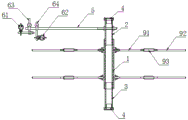
Fig. 1 is a schematic view of the overall structure of the tool for detecting the mounting accuracy of the rudder bearing base.
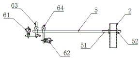
FIG. 2 is a schematic structural diagram of a tooling measurement mechanism for detecting the mounting accuracy of a rudder bearing base according to the present invention.
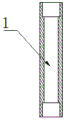
FIG. 3 is a schematic structural view of a tooling positioning sleeve for detecting the mounting accuracy of a rudder bearing base according to the present invention.
FIG. 4 is a schematic structural view of a tool rotating sleeve for detecting the mounting accuracy of a rudder bearing base according to the present invention.
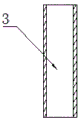
FIG. 5 is a schematic structural view of a fixture fixing sleeve for detecting the mounting accuracy of a rudder bearing base according to the present invention.
FIG. 6 is a schematic structural view of a tool illumination target for detecting the mounting accuracy of a rudder bearing base according to the present invention.
Fig. 7 is a schematic structural view of a tool positioning support frame for detecting the mounting accuracy of a rudder bearing base according to the present invention.
FIG. 8 is a schematic view of a telescopic positioning rod of the tooling for detecting the mounting accuracy of the rudder bearing base according to the present invention.
FIG. 9 is a sectional view of a rudder bearing base in the embodiment of the tooling for detecting the mounting accuracy of the rudder bearing base of the present invention.
FIG. 10 is a schematic view of the use state of the tool for detecting the mounting accuracy of the rudder bearing base.
FIG. 11 is an enlarged view of the area A in FIG. 10 of the tooling for detecting the mounting accuracy of the rudder bearing base according to the present invention.
FIG. 12 is an enlarged view of the area B in FIG. 10 of the tooling for detecting the mounting accuracy of the rudder bearing base according to the present invention.
FIG. 13 is an enlarged view of the area C in FIG. 10 of the tooling for detecting the mounting accuracy of the rudder bearing base according to the present invention.
In fig. 1 to 13: 1 is the location sleeve, 2 is rotatory sleeve, 21 is the connecting rod through-hole, 3 is the fixed sleeve, 4 is the illumination target, 41 is the target holder, 42 is the lens, 5 is the connecting rod, 51 is the threaded rod, 52 is the nut, 61 is the first percentage table, 62 is the second percentage table, 63 is first table frame, 64 is the second table frame, 7 is the location clamp, 8 is fastening bolt, 9 is flexible locating lever, 91 is first branch, 92 is the second branch, 93 is the screw thread, 10 is the rudder bearing base, 101 is the upper surface of rudder bearing base panel, 102 is the medial surface of rudder bearing base panel, 11 is the cabin deck, 12 is location lens, 13 is the location lens support, 14 is the rudder stock hole, 15 is the rudder pinhole.
Detailed Description
The tool for detecting the mounting accuracy of the rudder carrier base and the method for using the tool are further described in detail with reference to the accompanying drawings and specific embodiments, so as to clearly and clearly express the structural features and the specific applications of the invention, but the protection scope of the invention is not limited thereby.
Example (b): as shown in fig. 1 to 8, a tool for detecting the mounting accuracy of a rudder carrier base comprises a positioning mechanism and a measuring mechanism, wherein the positioning mechanism comprises a positioning sleeve 1 and a positioning support frame, the positioning support frame comprises a positioning hoop 7 and a plurality of telescopic positioning rods 9, the positioning hoop 7 is sleeved on the positioning sleeve 1, the plurality of telescopic positioning rods 9 are radially distributed around the positioning hoop 7, the central line of the telescopic positioning rods 9 is perpendicular to the central line of the positioning sleeve 1, the lower end of the positioning sleeve 1 is provided with a fixing sleeve 3, the upper end of the fixing sleeve 3 is in threaded connection with the lower end of the positioning sleeve 1, the central line of the fixing sleeve 3 is coincident with the central line of the positioning sleeve 1, the measuring mechanism comprises a rotating sleeve 2 and a connecting rod 5, the lower end of the rotating sleeve 2 is connected with the positioning sleeve 1, the central line of the rotating sleeve 2 is coincident with the central line of the positioning sleeve 1, the upper end of rotatory sleeve 2 and the lower extreme of positioning sleeve all are equipped with illumination target 4, rotatory sleeve 2 is connected with the one end of connecting rod 5, the central line of rotatory sleeve 2 is perpendicular with the central line of connecting rod 5, the percentage table is installed to the other end of connecting rod 5, the percentage table includes first percentage table 61 and second percentage table 62, the pointer of first percentage table 61 is vertical downwards, the pointer direction of second percentage table 62 is parallel with the central line of connecting rod 5, just the pointer direction of second percentage table 62 is rotatory sleeve dorsad.
In this embodiment, the pointer of the first dial indicator 61 is vertically downward and contacts with the upper surface 101 of the rudder carrier base panel to detect the flatness of the upper surface 101 of the rudder carrier base panel, and the pointer of the second dial indicator 62 contacts with the inner side surface 102 of the rudder carrier base panel to detect the concentricity of the inner side surface 102 of the rudder carrier base panel when in use; the end part of the connecting rod is provided with a first meter frame and a second meter frame, the first dial indicator is connected with the connecting rod through the first meter frame, and the second dial indicator is connected with the connecting rod through the second meter frame; the rotating sleeve 2 is provided with a connecting rod through hole 21, the central line of the connecting rod through hole 21 is perpendicular to the central line of the rotating sleeve 2, one end of the connecting rod 5 is provided with a threaded rod 51, the threaded rod 51 is arranged in the connecting rod through hole 21 in a penetrating manner, and a nut 52 is fastened on the threaded rod 51; the illumination target 4 comprises a target holder 41 and a lens 42, wherein the target holder 41 is of a cylindrical structure, the lens 42 is carved with a cross line, the lens 42 is installed on the target holder 41, the center line of the target holder 41 is superposed with the center line of the positioning sleeve 3, and the center line of the target holder 41 passes through the center of the cross line of the lens 42; the side surface of the positioning hoop 7 is provided with four threaded holes which are annularly distributed along the side surface of the positioning hoop 7, and fastening bolts 8 are arranged in the four threaded holes; the number of the positioning support frames is two, the two positioning support frames are both arranged on the positioning sleeve 1, and the two positioning support frames are respectively arranged at the upper end and the lower end of the positioning sleeve 1, so that the stability of the positioning support frames for supporting the positioning sleeve 1 is improved; telescopic positioning pole 9 all includes first branch 91 and second branch 92, the one end and the location clamp 7 of first branch 91 are connected, the other end and the second branch 92 of first branch 91 are connected through screw thread 93, and first branch 91 and second branch 92 are connected through screw thread 93, and first lead screw 91 and second lead screw 92 all with screw thread 93 threaded connection, through rotatory screw thread 93, adjust the degree of depth of first lead screw 91 and second lead screw 92 screw in screw thread 93, and then adjust telescopic positioning pole 9's overall length.
A use method of a tool for detecting the mounting accuracy of a rudder carrier base comprises the following steps:
step one, installing the rudder carrier base 10 in place on a rudder cabin deck 11, placing the tool in the rudder carrier base 10, and adjusting the screwing depth of the first support rod 91 and the second support rod 92 to enable the end part of the second screw rod 92 to be propped against the inner side wall of the rudder carrier base 10;
secondly, respectively placing a positioning lens 12 engraved with cross lines in a rudder stock hole 14 and a rudder pintle hole 15, connecting the positioning lens 12 placed in the rudder stock hole 14 with the side wall of the rudder stock hole 14 through a positioning lens support 13, connecting the positioning lens 12 placed in the rudder pintle hole 15 with the side wall of the rudder pintle hole 15 through another positioning lens support 13, enabling a rudder system center line to sequentially pass through the centers of the cross lines of the two positioning lenses 12, irradiating laser at the top of the rotary sleeve 2, enabling the light of the laser to sequentially pass through the centers of the cross lines of the two lenses 42, adjusting the depth of the first support rod 91 and the second support rod 92 screwed into the screw thread 93, enabling the light of the laser to sequentially pass through the centers of the cross lines of the two lenses 42 and the centers of the cross lines of the two positioning lenses 12, and enabling the positioning lens support 13 to be of a rod-shaped structure with telescopic length;
step three, adjusting the installation positions of the first dial indicator 61 and the second dial indicator 62 on the connecting rod 5, enabling the pointer of the first dial indicator 61 to be in contact with the upper surface 101 of the rudder bearing base panel, enabling the pointer of the second dial indicator 62 to be in contact with the inner side surface 102 of the rudder bearing base panel, and reading and recording the readings of the first dial indicator 61 and the second dial indicator 62;
step four, the readings of the first dial indicator 61 and the second dial indicator 62 are reset to zero, the rotating sleeve is rotated for 45 degrees, and the readings of the first dial indicator 61 and the second dial indicator 62 are read and recorded;
step five, repeating the step four until the rotary sleeve 2 rotates for a circle;
analyzing and comparing all readings measured by the first dial indicator 61, if the difference value between the maximum reading and the minimum reading measured by the first dial indicator 61 is less than or equal to 0.1mm, the flatness of the upper surface 101 of the rudder bearing base panel is qualified, and if the difference value between the maximum reading and the minimum reading measured by the first dial indicator 61 is greater than 0.1mm, a boring row needs to be built to bore the upper surface 101 of the rudder bearing base panel; and analyzing and comparing all the readings measured by the second dial indicator 62, if the difference value between the maximum reading and the minimum reading measured by the second dial indicator 62 is less than or equal to 0.2mm, the concentricity of the inner side surface 102 of the rudder bearing base panel is qualified, and if the difference value between the maximum reading and the minimum reading measured by the second dial indicator is more than 0.2mm, a boring bar needs to be set up to bore the inner side surface 102 of the rudder bearing base panel.
Fig. 9 shows a cross-sectional view of the rudder carrier base 10, fig. 10 shows a use state view of the tool, and fig. 11, 12 and 13 sequentially show enlarged views of a region a, a region B and a region C in fig. 10.
Claims (8)
1. The utility model provides a frock for detecting rudder carrier base installation accuracy, its characterized in that, this frock includes positioning mechanism and measuring mechanism, positioning mechanism includes location sleeve (1) and location support frame, location support frame includes location clamp (7) and a plurality of flexible locating lever (9), location clamp (7) cover is established on location sleeve (1), a plurality of flexible locating lever (9) are radial distribution around location clamp (7), the central line of flexible locating lever (9) is perpendicular with the central line of location sleeve (1), the lower extreme of location sleeve (1) is equipped with fixed sleeve (3), the upper end of fixed sleeve (3) and the lower extreme threaded connection of location sleeve (1), the central line of fixed sleeve (3) and the central line coincidence of location sleeve (1), measuring mechanism includes rotatory sleeve (2) and connecting rod (5), the lower extreme and the locating sleeve (1) of rotatory sleeve (2) are connected, the central line of rotatory sleeve (2) coincides with the central line of locating sleeve (1), the upper end of rotatory sleeve (2) and the lower extreme of fixed sleeve (3) all are equipped with illumination target (4), rotatory sleeve (2) are connected with the one end of connecting rod (5), the central line of rotatory sleeve (2) is perpendicular with the central line of connecting rod (5), the percentage table is installed to the other end of connecting rod (5), the percentage table includes first percentage table (61) and second percentage table (62), the pointer of first percentage table (61) is vertical downwards, the pointer direction of second percentage table (62) is parallel with the central line of connecting rod (5), just the pointer direction of second percentage table (62) is rotatory sleeve (2) dorsad.
2. The tool for detecting the mounting accuracy of the rudder bearing base according to claim 1, wherein a first gauge stand (63) and a second gauge stand (64) are arranged at the end of the connecting rod (5), the first dial indicator (61) is connected with the connecting rod (5) through the first gauge stand (63), and the second dial indicator (62) is connected with the connecting rod (5) through the second gauge stand (64).
3. The tool for detecting the mounting accuracy of the rudder bearing base according to claim 1, wherein the rotating sleeve (2) is provided with a connecting rod through hole (21), the central line of the connecting rod through hole (21) is perpendicular to the central line of the rotating sleeve (2), one end of the connecting rod (5) is provided with a threaded rod (51), the threaded rod (51) is arranged in the connecting rod through hole (21) in a penetrating manner, and a nut (52) is fastened on the threaded rod (51).
4. The tooling for detecting the mounting accuracy of the rudder bearing base is characterized in that the illumination target (4) comprises a target seat (41) and a lens (42), the target seat (41) is of a cylindrical structure, the lens (42) is carved with a cross line, the lens (42) is mounted on the target seat (41), the central line of the target seat (41) is coincident with the central line of the positioning sleeve (1), and the central line of the target seat (41) passes through the center of the cross line of the lens (42).
5. The tool for detecting the mounting accuracy of the rudder carrier base according to claim 1, wherein the side surface of the positioning clamp (7) is provided with a plurality of threaded holes, the plurality of threaded holes are annularly distributed along the side surface of the positioning clamp (7), and fastening bolts (8) are arranged in the plurality of threaded holes.
6. The tool for detecting the mounting accuracy of the rudder carrier base according to claim 1, wherein there are two positioning support frames, and the two positioning support frames are both mounted on the positioning sleeve (1).
7. The tooling for detecting the mounting accuracy of the rudder bearing base according to any one of the claims 1 to 6, wherein each telescopic positioning rod (9) comprises a first supporting rod (91) and a second supporting rod (92), one end of the first supporting rod (91) is connected with the positioning clamp (7), and the other end of the first supporting rod (91) is connected with one end of the second supporting rod (92) through a screw thread (93).
8. The use method of the tool for detecting the mounting accuracy of the rudder carrier base is characterized by comprising the following steps:
step one, installing a rudder carrier base (10) in place on a rudder cabin deck (11), placing a tool for detecting the installation accuracy of the rudder carrier base in the rudder carrier base (10), and adjusting the screwing depth of a first support rod (91) and a second support rod (92) into a screw thread (93) to enable the end part of the second screw rod (92) to be propped against the inner side wall of the rudder carrier base (10);
secondly, a positioning lens (12) carved with a cross line is respectively arranged in the rudder stock hole (14) and the rudder pin hole (15), the positioning lens (12) arranged in the rudder stock hole (14) is connected with the side wall of the rudder stock hole (14) through a positioning lens bracket (13), the positioning lens (12) arranged in the rudder pin hole (15) is connected with the side wall of the rudder pin hole (15) through another positioning lens bracket (13), and the central line of the rudder system passes through the centers of the cross lines of the two positioning lenses (12) in turn, irradiating laser into the top of the rotating sleeve (2), enabling the light of the laser to sequentially pass through the centers of the cross lines of the two lenses (42), adjusting the depth of the first supporting rod (91) and the second supporting rod (92) screwed into the screw thread (93), and enabling the light of the laser to sequentially pass through the centers of the cross lines of the two lenses (42) and the centers of the cross lines of the two positioning lenses (12);
thirdly, adjusting the mounting positions of the first dial indicator (61) and the second dial indicator (62) on the connecting rod (5), enabling a pointer of the first dial indicator (61) to be in contact with the upper surface (101) of the rudder bearing base panel, enabling a pointer of the second dial indicator (62) to be in contact with the inner side surface (102) of the rudder bearing base panel, and reading and recording the readings of the first dial indicator (61) and the second dial indicator (62);
the reading of the first dial indicator (61) and the reading of the second dial indicator (62) are reset to zero, the rotating sleeve (2) is rotated for 45 degrees, and the reading of the first dial indicator (61) and the reading of the second dial indicator (62) are read and recorded;
step five, repeating the step four until the rotary sleeve (2) rotates for a circle;
analyzing and comparing all readings measured by the first dial indicator (61), if the difference value between the maximum reading and the minimum reading measured by the first dial indicator (61) is less than or equal to 0.1mm, the flatness of the upper surface (101) of the rudder bearing base panel is qualified, and if the difference value between the maximum reading and the minimum reading measured by the first dial indicator (61) is greater than 0.1mm, a boring bar needs to be set up to bore the upper surface (101) of the rudder bearing base panel; and analyzing and comparing all readings measured by the second dial indicator (62), if the difference value between the maximum reading and the minimum reading measured by the second dial indicator (62) is less than or equal to 0.2mm, the concentricity of the inner side surface (102) of the rudder bearing base panel is qualified, and if the difference value between the maximum reading and the minimum reading measured by the second dial indicator (62) is more than 0.2mm, a boring row is required to be built to bore the inner side surface (102) of the rudder bearing base panel.
Priority Applications (2)
| Application Number | Priority Date | Filing Date | Title |
|---|---|---|---|
| CN201710757613.3A CN107643039B (en) | 2017-08-29 | 2017-08-29 | Tool for detecting mounting precision of rudder bearing base and using method thereof |
| CN201711400282.4A CN108195275B (en) | 2017-08-29 | 2017-08-29 | Use method of tool for detecting mounting precision of rudder bearing base |
Applications Claiming Priority (1)
| Application Number | Priority Date | Filing Date | Title |
|---|---|---|---|
| CN201710757613.3A CN107643039B (en) | 2017-08-29 | 2017-08-29 | Tool for detecting mounting precision of rudder bearing base and using method thereof |
Related Child Applications (1)
| Application Number | Title | Priority Date | Filing Date |
|---|---|---|---|
| CN201711400282.4A Division CN108195275B (en) | 2017-08-29 | 2017-08-29 | Use method of tool for detecting mounting precision of rudder bearing base |
Publications (2)
| Publication Number | Publication Date |
|---|---|
| CN107643039A CN107643039A (en) | 2018-01-30 |
| CN107643039B true CN107643039B (en) | 2020-04-14 |
Family
ID=61110919
Family Applications (2)
| Application Number | Title | Priority Date | Filing Date |
|---|---|---|---|
| CN201711400282.4A Active CN108195275B (en) | 2017-08-29 | 2017-08-29 | Use method of tool for detecting mounting precision of rudder bearing base |
| CN201710757613.3A Active CN107643039B (en) | 2017-08-29 | 2017-08-29 | Tool for detecting mounting precision of rudder bearing base and using method thereof |
Family Applications Before (1)
| Application Number | Title | Priority Date | Filing Date |
|---|---|---|---|
| CN201711400282.4A Active CN108195275B (en) | 2017-08-29 | 2017-08-29 | Use method of tool for detecting mounting precision of rudder bearing base |
Country Status (1)
| Country | Link |
|---|---|
| CN (2) | CN108195275B (en) |
Families Citing this family (8)
| Publication number | Priority date | Publication date | Assignee | Title |
|---|---|---|---|---|
| CN108955501A (en) * | 2018-08-27 | 2018-12-07 | 濮阳市鸿宇压力容器有限公司 | A kind of detection device rotating cleaner |
| CN109186427A (en) * | 2018-09-28 | 2019-01-11 | 中船重工(武汉)船舶与海洋工程装备设计有限公司 | A kind of shafting brearing bore center line detecting tooling and detection method |
| CN110901854B (en) * | 2019-10-29 | 2021-06-01 | 沪东中华造船(集团)有限公司 | Method for adjusting eccentricity of rudder stock |
| CN111439351B (en) * | 2020-03-26 | 2021-09-28 | 中船澄西船舶修造有限公司 | Plunger type hydraulic steering engine installation detection device |
| CN111878065B (en) * | 2020-07-15 | 2023-05-16 | 中国一冶集团有限公司 | Device and method for monitoring center deviation of pile foundation in construction of percussion drilling bored pile |
| CN113587784A (en) * | 2021-07-27 | 2021-11-02 | 中船澄西扬州船舶有限公司 | Novel steering engine alignment positioning device and using method thereof |
| CN114203003B (en) * | 2021-11-23 | 2023-04-21 | 华中科技大学 | Multifunctional simulation test device for ship |
| CN114485315B (en) * | 2021-12-31 | 2023-12-22 | 国家能源集团宁夏煤业有限责任公司 | Inner peripheral wall detection device and cylinder body detection equipment |
Citations (9)
| Publication number | Priority date | Publication date | Assignee | Title |
|---|---|---|---|---|
| CN2084603U (en) * | 1989-11-12 | 1991-09-11 | 青州水泵厂 | Inner hole centering device |
| WO2001004573A1 (en) * | 1999-07-12 | 2001-01-18 | Re-Source America, I.P., Inc. | Flatness tester for shipping trays |
| CN101618465A (en) * | 2009-07-10 | 2010-01-06 | 上海江南长兴造船有限责任公司 | Method for boring hole on screw shaft pipe subsection in supertanker construction |
| CN101723057A (en) * | 2010-01-21 | 2010-06-09 | 江南造船(集团)有限责任公司 | Installation method of ship single shafting without setting front bearing of stern shaft tube |
| CN202471021U (en) * | 2011-12-27 | 2012-10-03 | 上海重型机器厂有限公司 | Measurer for axiality of barrel |
| CN103090765A (en) * | 2013-01-28 | 2013-05-08 | 江苏一汽铸造股份有限公司 | Wind-electricity bearing-seat size and geometric-tolerance detection tool and installation detection method thereof |
| CN103322891A (en) * | 2013-06-27 | 2013-09-25 | 林全忠 | Method for detecting coaxiality of machine body |
| CN106217136A (en) * | 2016-06-13 | 2016-12-14 | 宁波市镇海峻诚文化传媒有限公司 | A kind of multifunctional guy illuminating apparatus |
| CN206540509U (en) * | 2016-12-16 | 2017-10-03 | 杭州鹤见南方泵业有限公司 | A kind of pump case axiality and flatness detect fixture |
Family Cites Families (1)
| Publication number | Priority date | Publication date | Assignee | Title |
|---|---|---|---|---|
| RO117813B1 (en) * | 1997-10-20 | 2002-07-30 | Iulian Dumitriu | Method and apparatus for measuring deviations from smoothness of surfaces |
-
2017
- 2017-08-29 CN CN201711400282.4A patent/CN108195275B/en active Active
- 2017-08-29 CN CN201710757613.3A patent/CN107643039B/en active Active
Patent Citations (9)
| Publication number | Priority date | Publication date | Assignee | Title |
|---|---|---|---|---|
| CN2084603U (en) * | 1989-11-12 | 1991-09-11 | 青州水泵厂 | Inner hole centering device |
| WO2001004573A1 (en) * | 1999-07-12 | 2001-01-18 | Re-Source America, I.P., Inc. | Flatness tester for shipping trays |
| CN101618465A (en) * | 2009-07-10 | 2010-01-06 | 上海江南长兴造船有限责任公司 | Method for boring hole on screw shaft pipe subsection in supertanker construction |
| CN101723057A (en) * | 2010-01-21 | 2010-06-09 | 江南造船(集团)有限责任公司 | Installation method of ship single shafting without setting front bearing of stern shaft tube |
| CN202471021U (en) * | 2011-12-27 | 2012-10-03 | 上海重型机器厂有限公司 | Measurer for axiality of barrel |
| CN103090765A (en) * | 2013-01-28 | 2013-05-08 | 江苏一汽铸造股份有限公司 | Wind-electricity bearing-seat size and geometric-tolerance detection tool and installation detection method thereof |
| CN103322891A (en) * | 2013-06-27 | 2013-09-25 | 林全忠 | Method for detecting coaxiality of machine body |
| CN106217136A (en) * | 2016-06-13 | 2016-12-14 | 宁波市镇海峻诚文化传媒有限公司 | A kind of multifunctional guy illuminating apparatus |
| CN206540509U (en) * | 2016-12-16 | 2017-10-03 | 杭州鹤见南方泵业有限公司 | A kind of pump case axiality and flatness detect fixture |
Also Published As
| Publication number | Publication date |
|---|---|
| CN108195275B (en) | 2020-04-14 |
| CN108195275A (en) | 2018-06-22 |
| CN107643039A (en) | 2018-01-30 |
Similar Documents
| Publication | Publication Date | Title |
|---|---|---|
| CN107643039B (en) | Tool for detecting mounting precision of rudder bearing base and using method thereof | |
| CN100507436C (en) | Meter for conic hole | |
| CN208383045U (en) | A kind of two sections of coaxiality detecting tools | |
| CN108177024B (en) | Tool rest positioning precision and repeated positioning precision detection device and use method | |
| CN104457668A (en) | Portable axle diameter measuring instrument | |
| CN100523710C (en) | Measurer for measuring distance between off-centering taper hole and periphery of revolution body | |
| CN105423843A (en) | Integrated raceway measuring instrument for bearing | |
| CN2932303Y (en) | Inside diameter measuring device | |
| CN200968845Y (en) | Device for measuring distance between rotary part eccentric hole and excircle | |
| CN212779065U (en) | Device for detecting verticality of rod piece on bolt ball | |
| CN102967246A (en) | Inner cone obliquity steel ball measuring gauge and measuring method thereof | |
| CN211552699U (en) | Verticality measuring tool for long bolt installation screw hole | |
| CN110779418A (en) | Method for measuring length of cone on line by double meters | |
| CN103234424A (en) | Measurer for outer diameters of valve seats | |
| CN202630902U (en) | Laser measure seat used for fixture installation | |
| CN213688184U (en) | Sealing plug verticality gauge | |
| CN113654779B (en) | Device and method for testing conical surface stress relaxation | |
| CN211651487U (en) | Threaded hole verticality measuring device | |
| CN210664301U (en) | Portable long stud coaxiality measuring tool | |
| CN111426259A (en) | Detection device and method for medium-large-aperture parts | |
| CN203177784U (en) | Gauge for measuring excircle dimension and roundness of part | |
| CN209055060U (en) | A kind of coaxiality check fixture of the support of bearing | |
| CN211717363U (en) | Detection device for medium and large aperture parts | |
| CN106017373A (en) | Flywheel cover basin mouth and end face run-out detection device | |
| CN219945894U (en) | Positioning device and detection system for measuring arbitrary reference axis in space |
Legal Events
| Date | Code | Title | Description |
|---|---|---|---|
| PB01 | Publication | ||
| PB01 | Publication | ||
| SE01 | Entry into force of request for substantive examination | ||
| SE01 | Entry into force of request for substantive examination | ||
| GR01 | Patent grant | ||
| GR01 | Patent grant |