CN107640277B - Bicycle speed variator - Google Patents
Bicycle speed variator Download PDFInfo
- Publication number
- CN107640277B CN107640277B CN201710601647.3A CN201710601647A CN107640277B CN 107640277 B CN107640277 B CN 107640277B CN 201710601647 A CN201710601647 A CN 201710601647A CN 107640277 B CN107640277 B CN 107640277B
- Authority
- CN
- China
- Prior art keywords
- connecting member
- transmission
- operating configuration
- locking device
- locking
- Prior art date
- Legal status (The legal status is an assumption and is not a legal conclusion. Google has not performed a legal analysis and makes no representation as to the accuracy of the status listed.)
- Active
Links
Images


Classifications
-
- B—PERFORMING OPERATIONS; TRANSPORTING
- B62—LAND VEHICLES FOR TRAVELLING OTHERWISE THAN ON RAILS
- B62M—RIDER PROPULSION OF WHEELED VEHICLES OR SLEDGES; POWERED PROPULSION OF SLEDGES OR SINGLE-TRACK CYCLES; TRANSMISSIONS SPECIALLY ADAPTED FOR SUCH VEHICLES
- B62M9/00—Transmissions characterised by use of an endless chain, belt, or the like
- B62M9/04—Transmissions characterised by use of an endless chain, belt, or the like of changeable ratio
- B62M9/06—Transmissions characterised by use of an endless chain, belt, or the like of changeable ratio using a single chain, belt, or the like
- B62M9/10—Transmissions characterised by use of an endless chain, belt, or the like of changeable ratio using a single chain, belt, or the like involving different-sized wheels, e.g. rear sprocket chain wheels selectively engaged by the chain, belt, or the like
- B62M9/12—Transmissions characterised by use of an endless chain, belt, or the like of changeable ratio using a single chain, belt, or the like involving different-sized wheels, e.g. rear sprocket chain wheels selectively engaged by the chain, belt, or the like the chain, belt, or the like being laterally shiftable, e.g. using a rear derailleur
- B62M9/121—Rear derailleurs
- B62M9/124—Mechanisms for shifting laterally
- B62M9/1244—Mechanisms for shifting laterally limiting or positioning the movement
-
- B—PERFORMING OPERATIONS; TRANSPORTING
- B62—LAND VEHICLES FOR TRAVELLING OTHERWISE THAN ON RAILS
- B62M—RIDER PROPULSION OF WHEELED VEHICLES OR SLEDGES; POWERED PROPULSION OF SLEDGES OR SINGLE-TRACK CYCLES; TRANSMISSIONS SPECIALLY ADAPTED FOR SUCH VEHICLES
- B62M9/00—Transmissions characterised by use of an endless chain, belt, or the like
- B62M9/04—Transmissions characterised by use of an endless chain, belt, or the like of changeable ratio
- B62M9/06—Transmissions characterised by use of an endless chain, belt, or the like of changeable ratio using a single chain, belt, or the like
- B62M9/10—Transmissions characterised by use of an endless chain, belt, or the like of changeable ratio using a single chain, belt, or the like involving different-sized wheels, e.g. rear sprocket chain wheels selectively engaged by the chain, belt, or the like
- B62M9/12—Transmissions characterised by use of an endless chain, belt, or the like of changeable ratio using a single chain, belt, or the like involving different-sized wheels, e.g. rear sprocket chain wheels selectively engaged by the chain, belt, or the like the chain, belt, or the like being laterally shiftable, e.g. using a rear derailleur
- B62M9/121—Rear derailleurs
- B62M9/128—Accessories, e.g. protectors
-
- B—PERFORMING OPERATIONS; TRANSPORTING
- B62—LAND VEHICLES FOR TRAVELLING OTHERWISE THAN ON RAILS
- B62M—RIDER PROPULSION OF WHEELED VEHICLES OR SLEDGES; POWERED PROPULSION OF SLEDGES OR SINGLE-TRACK CYCLES; TRANSMISSIONS SPECIALLY ADAPTED FOR SUCH VEHICLES
- B62M9/00—Transmissions characterised by use of an endless chain, belt, or the like
- B62M9/04—Transmissions characterised by use of an endless chain, belt, or the like of changeable ratio
- B62M9/06—Transmissions characterised by use of an endless chain, belt, or the like of changeable ratio using a single chain, belt, or the like
- B62M9/10—Transmissions characterised by use of an endless chain, belt, or the like of changeable ratio using a single chain, belt, or the like involving different-sized wheels, e.g. rear sprocket chain wheels selectively engaged by the chain, belt, or the like
- B62M9/12—Transmissions characterised by use of an endless chain, belt, or the like of changeable ratio using a single chain, belt, or the like involving different-sized wheels, e.g. rear sprocket chain wheels selectively engaged by the chain, belt, or the like the chain, belt, or the like being laterally shiftable, e.g. using a rear derailleur
- B62M9/121—Rear derailleurs
- B62M9/125—Mounting the derailleur on the frame
Landscapes
- Engineering & Computer Science (AREA)
- Chemical & Material Sciences (AREA)
- Combustion & Propulsion (AREA)
- Transportation (AREA)
- Mechanical Engineering (AREA)
- Steering Devices For Bicycles And Motorcycles (AREA)
- Axle Suspensions And Sidecars For Cycles (AREA)
- Gear-Shifting Mechanisms (AREA)
- Automatic Cycles, And Cycles In General (AREA)
Abstract
The present invention relates to a bicycle shifter (10) including an actuating link (20) and a connecting member (30). The actuating link includes a first body (24), a second body (26), and a pair of hinge levers (28). The first body is connected to the connecting member. The connecting member is fixed to the frame. A locking device (32) acting between the connecting member and the first body is switchable between a first operating configuration and a second operating configuration. The locking device (32) comprises a pin (34), the pin (34) comprising an actuating end (34a) and an opposite locking end (34b), the actuating end (34a) being intended to be actuated commanding a passage from the first operating configuration to the second operating configuration, and the locking end (34b) abutting against the connecting member (30) when the locking device (32) is in the second operating configuration. When the locking device (32) is in the second operating configuration, the actuating end (34a) is arranged on one side of the connecting member (30) and the locking end (34b) is arranged on the other side of the connecting member (30).
Description
Technical Field
The present invention relates to a bicycle derailleur, preferably a racing bicycle derailleur.
Background
In the context of the present invention, the derailleur of particular interest is a rear derailleur that moves a chain between different sprockets of a sprocket assembly associated with a rear wheel of a bicycle.
The movement of the chain is typically actuated by the movement of a derailleur associated with an actuating link associated with the bicycle frame at the rear wheel.
The bicycle transmission can be mechanically actuated or motorized. In the first case, the movement of the derailleur is performed by using a sheathed wire (so-called bowden cable). In the second case, the movement of the derailleur is performed by using a suitably driven, usually electrically driven, drive member. The action of the sheath wire or drive member on the actuating link causes the actuating link to deform, thus causing movement of the derailleur.
The actuating link generally includes a first body configured to be rotatably coupled to the bicycle frame, a second body configured to support the derailleur, and a pair of hinge levers coupling the first body and the second body.
In order to facilitate the removal/reinstallation of the rear wheel (for example, in the case of rear wheel tyre puncturing), rear derailleurs provided with a derailleur locking device are known. These locking devices lock the transmission in a pulled-back position with respect to the position occupied in the operating state of normal operation of the transmission. This allows the upper pulley of the derailleur of the transmission to be moved to a position so as not to impede the removal/reattachment of the rear wheel of the bicycle to the bicycle frame.
EP 1902936 describes a locking device of a bicycle derailleur, which is arranged between a connecting member of an actuating link to a bicycle frame and a first body of the actuating link. The connecting member is fixed to the frame by an attachment screw, while the first body is rotatably connected to the connecting member at an axis of rotation and moves between an unlocked position of the transmission and a locked position of the transmission, the positions being angularly spaced apart. The locking device is configured to selectively retain the first body in a locked position and includes a first pin that acts on a spring received within a blind cavity of the first body, wherein when the first body is in the locked position, the spring is in a preloaded state and pushes the first pin into a recess formed in the connecting member. Such a recess is defined within a stepped through-hole formed in the connecting member. A second pin is mounted within such a stepped through-hole, said second pin comprising an actuating end portion protruding from the connecting member on the opposite side with respect to the first body. The second pin is actuated to push the first pin outside the recess so as to be able to rotate the first body with respect to the connecting member into the unlocked position.
The applicant has noticed that the locking device of the bicycle derailleur described in the above-mentioned prior art document requires two distinct cavities (a blind cavity in the first body, and a stepped through hole in the connecting member) in which two distinct pins (the first pin and the second pin) slide. This results in a complicated construction and structure. Furthermore, the two chambers exposed to the outside can be containers of dirt or water, with the risk of compromising the correct operation of the locking device.
The problem underlying the present invention is to provide a bicycle derailleur comprising a locking device which is simpler and more reliable in construction than that described above with reference to the prior art.
Disclosure of Invention
Accordingly, the present invention is directed to a bicycle shifter comprising:
an actuating link configured to deform in order to move a derailleur of the transmission, the actuating link comprising a first body configured to be rotatably coupled to a bicycle frame, a second body configured to support the derailleur of the transmission, and a pair of hinge levers connecting the first body and the second body;
-a connecting member for connecting the actuating link to a bicycle frame, wherein the first body is rotatably connected to the connecting member at the rotational axis and the connecting member is configured to be fixed to the frame;
-locking means acting between the connecting member and the first body and selectively actuatable to switch between a first operating configuration in which the first body is free to move about the axis of rotation with respect to the connecting member, and a second operating configuration in which the first body is held in a predetermined angular position with respect to the connecting member;
-characterized in that the locking device comprises a pin slidable along a sliding axis inside a through cavity formed on the first body and comprising an actuating end to be actuated commanding the passage from the first operating configuration to the second operating configuration and an opposite locking end abutting the connecting member when the locking device is in the second operating configuration, thus preventing the relative rotation between the first body and the connecting member, wherein when the locking device is in the second operating configuration the actuating end is arranged at one side of the connecting member and the locking end is arranged at the other side of the connecting member.
Advantageously, providing a single pin sliding within a single through cavity makes the locking device of the invention simpler and more reliable to construct than the locking devices described above with reference to the prior art.
In the above-described locking device, the locking of the transmission is obtained only by the abutment of the locking end portion of the pin against the connecting member.
Preferred features of the bicycle derailleur according to the invention are described below, wherein these features can be provided individually or in combination with each other.
Preferably, when the locking means is in the second operative configuration, the locking end abuts against a lower surface and a rear surface of the connecting member.
In the present description and in the following claims, the terms "lower", "rear" and "front" surface of the connecting member are used to indicate the surfaces located below, behind and in front of the connecting member, respectively, with reference to their relative position with respect to the first body and the position of the connecting member when mounted on the bicycle frame. In particular, the lower surface of the connecting member is a downwardly facing surface, the front surface of the connecting member being on its side facing towards the first body and the rear surface of the connecting member being on its other side facing away from the first body.
In an embodiment of the invention, the locking end comprises a shank terminating in an enlarged head, wherein the shank abuts the lower surface of the connecting member and the enlarged head abuts the rear surface of the connecting member when the locking device is in the second operative configuration.
In an alternative embodiment, the locking end comprises a shank comprising a circumferential recess housing a resilient washer, wherein when the locking device is in the second operative configuration, the shank abuts the lower surface of the connecting member and the resilient washer abuts the rear surface of the connecting member.
Preferably, the locking means comprise an elastic element which is housed in the through cavity in a preloaded condition and acts between the actuation end and an abutment surface defined in the through cavity.
More preferably, the elastic member is a coil spring.
Advantageously, when the locking device is in its first operating configuration, i.e. when the locking end of the pin is not abutting against the connecting member, the elastic element is in the rest configuration and keeps the pin away from the connecting member.
In a first preferred embodiment of the present invention, the connecting member is a bracket rotatably connected to the first body by a first rotating pin coaxial with the rotation axis and configured to be fixed to the vehicle frame by a first attachment screw arranged at an attachment axis different from the rotation axis.
In a second preferred embodiment of the invention, said connecting member is a bushing rotatably connected to the first body by a second rotation pin coaxial with the rotation axis and configured to be fixed to the frame by a second attachment screw made integral with a free end of said second rotation pin.
Advantageously, the bushing makes it possible to impart greater compactness to the bicycle derailleur. Due to the fact that the second rotation pin is made in one piece with the second attachment screw, a faster mounting/dismounting of the bicycle transmission to/from the frame is also obtained.
Preferably, the connecting member and the first body include an end stop adjustment arrangement configured to adjust an end stop corner position of the first body relative to the connecting member when the locking arrangement is in the first operative configuration.
More preferably, said end stop adjustment means comprise an adjustment screw screwed into a threaded seat made integral with one of said connecting member and said first body and having an end portion that rests against an abutment element fixedly associated with the other of said connecting member and said first body.
In a preferred embodiment of the invention, an elastic torsion element is provided between the connecting member and the first body, the elastic torsion element being coaxial with the rotation axis.
Preferably, the elastic torsion element is a helical torsion spring.
Advantageously, thanks to the provision of the torsion spring element, the second operating configuration is maintained in an extremely stable manner, thus reducing the risk of the bicycle derailleur accidentally losing the second configuration when a possible impact is received during the step of disassembling the wheel.
Drawings
Other features and advantages of the present invention will become more apparent from the following detailed description of the preferred embodiments thereof, given for indicative and non-limiting purposes, with reference to the accompanying drawings. In these drawings:
FIG. 1 is a perspective view of a first preferred embodiment of a bicycle shifter in accordance with the present invention, with the bicycle shifter in its normal operating configuration;
FIG. 2 is a perspective view of the bicycle shifter of FIG. 1, with the bicycle shifter in a locked operating configuration;
FIG. 3 is another perspective view of the bicycle derailleur of FIG. 1, taken from the opposite point of view from FIG. 1;
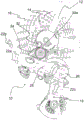
FIG. 4 is a partial cross-sectional perspective view of an enlarged portion of the bicycle transmission of FIG. 3;
FIG. 5 is another perspective view of the bicycle derailleur of FIG. 2, taken from the opposite viewpoint as FIG. 2;
FIG. 6 is an exploded perspective view of a second preferred embodiment of the bicycle shifter according to the present invention;
FIG. 7 is a perspective view of a third preferred embodiment of the bicycle transmission in accordance with the present invention, with the bicycle transmission in its normal operating configuration;
FIG. 8 is a perspective view of the bicycle shifter of FIG. 7, with the bicycle shifter in a locked operating configuration;
FIG. 9 is another perspective view of the bicycle shifter of FIG. 7, taken from the opposite viewpoint from FIG. 7;
fig. 10 is another perspective view of the bicycle shifter of fig. 8, taken from the opposite point of view from fig. 8.
Detailed Description
In fig. 1 to 5, reference numeral 10 designates a bicycle derailleur, particularly a rear derailleur, in accordance with a first preferred embodiment of the present invention.
The rear derailleur 10 is mounted on a bicycle frame 12 (fig. 1 and 2) and moves a chain (not shown) between different sprockets 14 of a sprocket assembly 16 associated with a rear wheel (not shown) of the bicycle.
The movement of the chain is actuated by movement of the derailleur 18 (or chain guide) associated with the actuating link 20.
The transmission 10 can be mechanically actuated or motorized. The drawings show, as a non-limiting example, a motorized transmission in which movement of the derailleur 18 is performed by using a drive member 22 that is typically electrically suitably driven. Once driven, the actuating link 20 deforms to move the derailleur 18.
The actuating link 20 is an articulated quadrilateral link, preferably in the form of an articulated parallelogram. The actuating link 20 includes a first body 24 configured to be rotatably coupled to the bicycle frame 12, a second body 26 configured to support the derailleur 18, and a pair of hinge levers 28 connecting the first and second bodies 24, 26. The levers 28 are also referred to as "inner levers" and "outer levers," respectively, with reference to their relative positions with respect to the bicycle frame.
The pre-tensioned spring is disposed between the second body 26 and the derailleur 18 in a per se conventional manner.
In the example shown herein, the drive member 22 is housed within the first body 24 and commands the deformation of the actuating link 20, lengthening or shortening the diagonal of the articulated quadrilateral. In particular, this diagonal lengthening is used to perform upshifting (toward the sprocket 14 having a larger diameter), whereas the diagonal shortening is used to downshift (toward the sprocket 14 having a smaller diameter).
The drive member 22 includes a motor 22a fixedly connected to the first body 24 (powered and driven by the cable and the drive member 22 b), and a transmission element 22c rotationally driven by the motor 22 a. For example, the transmission element 22c is defined by a transmission shaft of the electric motor 22 a.
The transmission 10 includes a connecting member 30 for connecting the actuating link 20 to the bicycle frame 12. Such a connecting member 30 is fixed to the frame 12.
The first body 24 is rotatably connected to the connecting member 30 at the rotation axis X. Preferably, no element for adjusting the reciprocating position thereof is provided between the connecting member 30 and the frame 12.
In particular, in this first preferred embodiment of the invention, the connecting member 30 is a bracket 31, the bracket 31 being rotatably connected to the first body 24 by a first rotation pin 31a coaxial with the rotation axis X and being fixed to the frame 12 by a first attachment screw 31b arranged at an attachment axis Z different from the rotation axis X (fig. 2 and 3). Preferably, the attachment axis Z is substantially parallel to the rotation axis X (as shown in fig. 1).
As shown in fig. 3 and 4, the first rotation pin 31a is mounted on the connection member by an elastic washer 31c fitted in a circumferential recess 31d thereof. Preferably, the elastic washer 31c is shaped like an open ring.
The transmission 10 further includes a locking device 32 acting between the connecting member 30 and the first body 24.
The locking device 32 is selectively actuatable to switch between a first operating configuration (shown in fig. 1, 3 and 4) in which the first body 24 is free to move about the rotation axis X with respect to the connecting member 30, and a second operating configuration (shown in fig. 2 and 5) in which the first body 24 is held in a predetermined angular position with respect to the connecting member 30.
As shown in fig. 2, in the second operating configuration, the transmission 10 is in a pulled-back position with respect to the position occupied in the first operating configuration of normal operation of the transmission 10 shown in fig. 1. This allows the upper pulley or sprocket 19a of the derailleur 18 to be moved away under the sprocket assembly 16, otherwise the upper pulley or sprocket 19a would prevent the rear wheel from being removed from the frame of the bicycle. In fact, the upper pulley 19a of the derailleur 18 is moved, leaving sufficient free space under the sprocket assembly 16 for removing and reinstalling the wheel.
The locking device 32 comprises a pin 34, the pin 34 being configured to slide along a sliding axis Y within a through cavity 36 formed on the first body 24. Preferably, the sliding axis Y is substantially parallel to the rotation axis X (as shown in fig. 1).
The pin 34 comprises a braking end 34a (preferably configured like a push-button), the braking end 34a being intended to be actuated to command the passage from the first operating configuration to the second operating configuration.
The pin 34 also includes an opposite locking end 34 b. As best shown in fig. 2 and 5, when the locking device 32 is in the second operative configuration, the locking end 34b abuts against the lower and rear surfaces of the connecting member 30, thus preventing relative rotation between the first body 24 and the connecting member 30. In this operating configuration, the locking end 34b is therefore arranged at the side of the connection configuration 30 opposite to the side on which the actuating end 34a is arranged. In particular, the actuating end 34a is arranged at the front side of the connecting member 30, i.e. on the side thereof facing towards the first body 24, while the locking end 34b is located on the other rear side thereof facing away with respect to the first body 24.
In this first preferred embodiment of the invention, as shown in fig. 4, the locking end 34b includes a shank 34c terminating in an enlarged head 34 d. When the locking device 32 is in the second operative configuration, the shank 34c abuts against the lower surface of the connecting member 30 and the enlarged head 34d abuts against the rear surface of the connecting member 30. The abutment between the shank 34c of the locking end 34b of the pin 34 and the connecting member 30 occurs at a shaped housing seat 30a formed in the connecting member 30. Such a shaped housing seat 30a is defined by a recess, which is in turn defined by a projecting portion 30b projecting from the lower surface of the connecting member 30.
As shown in fig. 4, the locking device 32 further comprises an elastic element 38 housed in the through cavity 36 in the preloaded condition. The elastic element 38 of the non-limiting example of fig. 4 is a helical spring. The elastic element 38 acts between the actuation end 34a and an abutment surface 36a defined inside the through cavity 36.
Furthermore, as shown in fig. 4, the locking device 32 comprises a resilient torsion element 40 arranged between the connecting member 30 and the first body 24. The elastic torsion element 40 is coaxial with the rotation axis X. The elastic torsion element 40 of the non-limiting example of fig. 4 is a helical torsion spring mounted around the first rotation pin 31 a.
The connecting member 30 and the first body 24 include an end stop adjustment device 42, the end stop adjustment device 42 being configured to adjust an end stop angular position of the first body 24 relative to the connecting member 30 when the locking device 32 is in the first operating configuration.
In the non-limiting example shown in the figures, the end stop adjustment means 42 comprise an adjustment screw 42a, which adjustment screw 42a is screwed into a threaded seat made in one piece with the first body 24 and has an end that abuts against an abutment element 42b fixedly associated with the connection member 30. Alternatively, there may be a variant embodiment (not shown) in which the adjustment screw 42a is screwed into a threaded seat made integral with the connecting member 30 and the abutment element 42 is fixedly associated with the first body 24.
FIG. 6 illustrates a second preferred embodiment of the bicycle shifter 10 in accordance with the present invention.
The components of the bicycle transmission 10 of fig. 6 that are similar or functionally equivalent to those of the bicycle transmission 10 of fig. 1-5 are designated with the same reference numerals and their description should be referenced to that described above.
The bicycle shifter 10 of fig. 6 basically differs from the bicycle shifter 10 of fig. 1-5 only in the pin 34 of the locking device 32, and in particular the locking end 34b of the pin 34.
In this second preferred embodiment, the locking end 34b includes a shank 134c, the shank 134c including a circumferential recess 134e that receives a corresponding resilient washer 134 d. When the locking device 32 is in the second operative configuration, the shank 134c abuts against the lower surface of the connecting member 30 and the resilient washer 134d abuts against the rear surface of the connecting member 30. Preferably, the elastic washer 134d is formed in an open ring shape.
Thus, the resilient washer 134d of the pin 34 of the bicycle shifter 10 of fig. 6 performs the same function as performed by the enlarged head portion 34d of the pin 34 of the bicycle shifter 10 of fig. 1-5.
7-10 illustrate a third preferred embodiment of a bicycle shifter in accordance with the present invention.
The components of the bicycle transmission 10 of fig. 7-10 that are similar or functionally equivalent to those of the bicycle transmission 10 of fig. 1-5 are designated with the same reference numerals and their description should be referenced to that which is described above.
The bicycle shifter 10 of fig. 7-10 basically differs from the bicycle shifter 10 of fig. 1-5 only in that the connecting member 30 is the bushing 231 instead of the bracket 31.
Such a bush 231 is rotatably connected to the first body 24 by a second rotation pin 231a, the second rotation pin 231a being associated with the rotation axis X and being fixed to the frame by a second attachment screw (not shown), preferably made in one piece at the free end of the second rotation pin 231 a. The second attachment screw is coaxial with the second rotation pin 231a and thus with the rotation axis X.
During travel, the bicycle shifter 10 is generally in a first operating configuration (shown in fig. 1, 3, 4, 7 and 9) in which the first body 24 is free to move about the rotational axis X with respect to the connecting member 30 to allow the chain to move between the different sprockets 14 of the sprocket assembly 16 associated with the rear wheel of the bicycle.
To allow the derailleur 18 to be positioned in a position suitable for making rear wheel changes of the bicycle easier, the locking device 32 is actuated to shift to a second operating configuration (shown in fig. 2, 5, 8 and 10) in which the first body 24 is positioned and held in a predetermined angular position with respect to the connecting member 30.
As mentioned above, in the second operating configuration, the transmission 10 is in a position in which the upper pulley 19b of the derailleur 18 (which is a pulley that normally prevents the rear wheel of a bicycle from backing out of its base) is moved and sufficient free space is left under the sprocket assembly 16.
The locking device 32 is mainly used in particular in transmissions provided with a clutch for stabilizing the vibrations of the chain, wherein such a clutch is a further obstacle when the rear wheels are dismounted.
The first body 24 is caused to rotate in one rotational direction (clockwise, with reference to figures 1 and 7) about the rotation axis X until it reaches a predetermined angular position with respect to the connecting member 30, so that the actuating end 34a can be pushed to move the locking end 34b of the pin 34 up to and beyond the connecting member 30. At this point, the first body 24 and the actuating end 34a are released, obtaining an abutment between the lower surface of the connecting member 30 and the shank 34c, 134c of the locking end 34b at the shaped housing seat 30a of the connecting member 30, and, by effect of the elastic return action exerted by the elastic element 38 on the pin 34, obtaining an abutment between the locking end 34b and the rear surface of the connecting member 30. In this way, locking of the transmission 10 in the above-mentioned angular position is obtained. In fact, in this position, the first body 24 cannot rotate in the opposite direction of rotation (anticlockwise, with reference to figures 1 and 7).
During rotation of the first body 24 to the second operating configuration, the derailleur 18 is extended by the pulling of the chain, and in particular, the upper pulley 19a of the derailleur 18 releases the channel under the sprocket assembly 16 for extracting the rear wheel.
A slight rotation of the first body 24 in the above-mentioned direction of rotation (clockwise, with reference to fig. 1 and 7) is sufficient to restore the transmission 10 to the first operating configuration, so that the locking end 34b of the pin 34 is released from the connecting member 30 due to the elastic restoring action exerted by the elastic element 38 on the pin 34. Thereafter, by rotating the first body 24 in the opposite direction (counterclockwise, with reference to fig. 1 and 7), the transmission 10 is restored to the first operating configuration.
When the locking device 32 is "unlocked", the first body 24 is transitioned to the first operating configuration and, with respect to the connecting member 30, occupies the operative and end-braking reciprocal angular position due to the chain-applied pull acting on the derailleur 18. The end stop adjustment device 242 has the function of adjusting the end stop angular position of the first body 24 with respect to the connecting member 30 when the locking device 32 is in the first operative configuration.
Upon rotation of the first body 24 in the above-mentioned direction of rotation (clockwise, with reference to figures 1 and 7), the possible elastic torsion element 40 provided between the connecting member 30 and the first body 24 is then loaded, so that the second operating configuration can be maintained in an extremely stable manner.
Of course, a person skilled in the art will be able to make numerous variations and modifications to the bicycle derailleur described above in order to satisfy specific and certain requirements, all of which are in any case covered by the scope of protection of the present invention, as defined by the following claims.
In particular, in the third preferred embodiment of fig. 7-10, a pin 34 can be used, wherein the locking end 34b is of the type shown in the second preferred embodiment of fig. 6, i.e. the pin 34 is provided with a corresponding elastic washer 134 d.
Furthermore, in all the preferred embodiments described above, the through cavity 36 can be formed on the connecting member 30 and, in this case, the locking end 34b of the pin 34 will abut against the first body 24, with a clear operation similar to that discussed above.
Claims (7)
1. A bicycle shifter (10), comprising:
-an actuating link (20), the actuating link (20) being configured to deform in order to move a derailleur (18) of the transmission, the actuating link (20) comprising a first body (24) configured to be rotatably connected to a bicycle frame (12), a second body (26) configured to support the derailleur (18) of the transmission, and a pair of hinge levers (28) connecting the first body (24) and the second body (26);
-a connecting member (30) for connecting the actuating link (20) to the bicycle frame (12), wherein the first body (24) is rotatably connected to the connecting member (30) at an axis of rotation (X), and the connecting member (30) is configured to be fixed to the frame (12);
-locking means (32) acting between the connection member (30) and the first body (24) and selectively actuatable to switch between a first operating configuration, in which the first body (24) is free to move about the rotation axis (X) with respect to the connection member (30), and a second operating configuration, in which the first body (24) is maintained in a predetermined angular position with respect to the connection member (30);
characterized in that said locking device (32) comprises a single pin (34), said pin (34) being slidable along a sliding axis (Y) in a through cavity (36) formed on said first body (24), and in that said pin (34) comprises an actuating end (34a) to be actuated in order to command the passage from said first operating configuration to said second operating configuration, and an opposite locking end (34b), said locking end (34b) abutting against said connecting member (30) when said locking device (32) is in said second operating configuration, thereby preventing the relative rotation between said first body (24) and said connecting member (30), wherein said actuating end (34a) is arranged at one side of said connecting member (30) when said locking device (32) is in said second operating configuration, and the locking end (34b) is arranged at the other side of the connecting member (30);
wherein when the locking device (32) is in the second operative configuration, the locking end (34b) abuts against a lower surface and a rear surface of the connecting member (30);
wherein the locking end (34b) comprises a shank (34c, 134c) terminating in an enlarged head (34d) or comprising a circumferential recess (134e) in which a resilient washer (134d) is accommodated, wherein when the locking device (32) is in the second operative configuration, the shank (34c, 134c) abuts against the lower surface of the connecting member (30) and the enlarged head (34d) or the resilient washer (134d) abuts against the rear surface of the connecting member (30);
wherein the abutment between the shank (34c, 134c) and the lower surface of the connecting member (30) occurs at a profiled housing seat (30a) formed in the lower surface of the connecting member (30).
2. The transmission (10) according to claim 1, wherein the locking device (32) comprises an elastic element (38), the elastic element (38) being housed in the through cavity (36) in a preloaded condition and acting between the actuation end (34a) and an abutment surface (36a) defined in the through cavity (36).
3. The transmission (10) according to claim 1, wherein the connecting member (30) is a bracket (31) rotatably connected to the first body (24) by a first rotation pin (31a) coaxial with the rotation axis (X) and configured to be fixed to the frame (12) by a first attachment screw (31b) arranged at an attachment axis (Z) different from the rotation axis (X).
4. The transmission (10) according to claim 1, wherein the connecting member (30) is a bushing (231) rotatably connected to the first body by a second rotation pin (231a) coaxial with the rotation axis (X) and configured to be fixed to the frame (12) by a second attachment screw made integral with a free end of the second rotation pin (231 a).
5. The transmission (10) of claim 1, wherein the connecting member (30) and the first body (24) include an end brake adjustment device (42) configured to adjust an end brake corner position of the first body (24) relative to the connecting member (30) when the locking device (32) is in the first operating configuration.
6. Transmission (10) according to claim 5, wherein said end stop adjustment means (42) comprise an adjustment screw (42a) screwed into a threaded seat made integral with one of said connecting member (30) and said first body (24) and having an end abutting against an abutment element (42b) fixedly associated with the other of said connecting member (30) and said first body (24).
7. The transmission (10) according to claim 1, wherein a torsion element (40) is provided between the connecting member (30) and the first body (24), the torsion element (40) being coaxial with the rotation axis (X).
Applications Claiming Priority (2)
| Application Number | Priority Date | Filing Date | Title |
|---|---|---|---|
| IT102016000076517 | 2016-07-21 | ||
| IT102016000076517A IT201600076517A1 (en) | 2016-07-21 | 2016-07-21 | BICYCLE CHANGE |
Publications (2)
| Publication Number | Publication Date |
|---|---|
| CN107640277A CN107640277A (en) | 2018-01-30 |
| CN107640277B true CN107640277B (en) | 2020-12-15 |
Family
ID=57610124
Family Applications (1)
| Application Number | Title | Priority Date | Filing Date |
|---|---|---|---|
| CN201710601647.3A Active CN107640277B (en) | 2016-07-21 | 2017-07-21 | Bicycle speed variator |
Country Status (6)
| Country | Link |
|---|---|
| US (1) | US10486769B2 (en) |
| EP (1) | EP3272634B1 (en) |
| JP (1) | JP6814705B2 (en) |
| CN (1) | CN107640277B (en) |
| IT (1) | IT201600076517A1 (en) |
| TW (1) | TWI730144B (en) |
Families Citing this family (3)
| Publication number | Priority date | Publication date | Assignee | Title |
|---|---|---|---|---|
| DE102018001253A1 (en) * | 2017-03-20 | 2018-09-20 | Sram Deutschland Gmbh | Rear derailleur for coaxial mounting |
| TWI680911B (en) * | 2018-08-22 | 2020-01-01 | 彥豪金屬工業股份有限公司 | Bicycle rear derailleur |
| DE102020000827A1 (en) * | 2019-04-25 | 2020-10-29 | Sram Deutschland Gmbh | Electromechanical switching mechanism for coaxial assembly |
Family Cites Families (27)
| Publication number | Priority date | Publication date | Assignee | Title |
|---|---|---|---|---|
| US3964330A (en) * | 1974-11-08 | 1976-06-22 | Maeda Industries, Ltd. | Chain guide connector device for use in bicycle derailleurs |
| FR2427243A1 (en) * | 1978-06-01 | 1979-12-28 | Huret Roger | CYCLE DERAILLEUR |
| IT1132005B (en) * | 1979-08-08 | 1986-06-25 | Huret & Fils | FRONT DERAILLEUR FOR BICYCLE |
| JPH0226794Y2 (en) * | 1985-06-17 | 1990-07-20 | ||
| JP2606242Y2 (en) * | 1993-02-03 | 2000-10-10 | 株式会社シマノ | Rear derailleur bracket for bicycle |
| US5498211A (en) * | 1994-11-29 | 1996-03-12 | Hsu; Yi-Hsung | Bicycle speed change mechanisms |
| US5961409A (en) * | 1996-12-26 | 1999-10-05 | Shimano, Inc. | Rear derailleur for a bicycle |
| US5931753A (en) * | 1998-02-09 | 1999-08-03 | Shimano, Inc. | Rear deraileur with shock absorber |
| EP1107902B1 (en) * | 1998-08-26 | 2003-12-03 | Shimano Inc. | Rear changer device for bicycle |
| US6287228B1 (en) * | 1999-11-12 | 2001-09-11 | Shimano, Inc. | Rear derailleur with cable guide roller |
| JP3708515B2 (en) | 2002-10-30 | 2005-10-19 | 株式会社シマノ | Bicycle rear derailleur |
| JP3667312B2 (en) * | 2002-10-30 | 2005-07-06 | 株式会社シマノ | Bicycle rear derailleur |
| US8277346B2 (en) * | 2006-02-28 | 2012-10-02 | Shimano, Inc. | Low profile rear derailleur |
| US20080051237A1 (en) * | 2006-08-24 | 2008-02-28 | Shimano Inc. | Bicycle rear derailleur |
| US7905804B2 (en) * | 2006-09-08 | 2011-03-15 | Shimano Inc. | Bicycle derailleur |
| US20080081716A1 (en) * | 2006-09-25 | 2008-04-03 | Shimano Inc. | Bicycle rear derailleur |
| US7722488B2 (en) * | 2006-09-25 | 2010-05-25 | Shimano Inc. | Bicycle rear derailleur |
| US8137223B2 (en) * | 2007-05-16 | 2012-03-20 | Shimano Inc. | Bicycle rear derailleur |
| US7942767B2 (en) * | 2007-12-19 | 2011-05-17 | Shimano, Inc. | Bicycle derailleur with multiple mounting adjustments |
| US7963870B2 (en) * | 2008-05-01 | 2011-06-21 | Shimano Inc. | Bicycle rear derailleur |
| US8142312B2 (en) * | 2008-07-02 | 2012-03-27 | Shimano Inc. | Bicycle rear derailleur |
| DE102011118912A1 (en) * | 2011-11-18 | 2013-05-23 | Sram Deutschland Gmbh | A derailleur device for a bicycle circuit, in particular rear derailleur device |
| US9334016B2 (en) * | 2012-07-13 | 2016-05-10 | Shimano Inc. | Bicycle rear derailleur |
| ITMI20131825A1 (en) * | 2013-11-04 | 2015-05-05 | Campagnolo Srl | MOTORIZED DRIVE DERAILLEUR FOR A BICYCLE CHANGE |
| ITMI20131949A1 (en) * | 2013-11-22 | 2015-05-23 | Campagnolo Srl | ASSEMBLY DEVICE FOR A FRONT DERAILLEUR OF A REAR TRANSMISSION ON A BICYCLE FRAME |
| DE102014225036A1 (en) * | 2013-12-23 | 2015-06-25 | Sram Deutschland Gmbh | Bicycle decanter with friction damping |
| ITMI20142069A1 (en) * | 2014-12-02 | 2016-06-02 | Campagnolo Srl | DERAILLEUR OF A BICYCLE CHANGE AND METHOD OF ELECTRONICALLY CONTROL OF A BICYCLE CHANGE |
-
2016
- 2016-07-21 IT IT102016000076517A patent/IT201600076517A1/en unknown
-
2017
- 2017-07-11 EP EP17180674.8A patent/EP3272634B1/en active Active
- 2017-07-12 TW TW106123281A patent/TWI730144B/en active
- 2017-07-17 US US15/651,495 patent/US10486769B2/en active Active
- 2017-07-19 JP JP2017139850A patent/JP6814705B2/en active Active
- 2017-07-21 CN CN201710601647.3A patent/CN107640277B/en active Active
Also Published As
| Publication number | Publication date |
|---|---|
| IT201600076517A1 (en) | 2018-01-21 |
| JP2018058574A (en) | 2018-04-12 |
| US10486769B2 (en) | 2019-11-26 |
| US20180022417A1 (en) | 2018-01-25 |
| EP3272634B1 (en) | 2019-11-06 |
| EP3272634A1 (en) | 2018-01-24 |
| TW201803770A (en) | 2018-02-01 |
| CN107640277A (en) | 2018-01-30 |
| JP6814705B2 (en) | 2021-01-20 |
| TWI730144B (en) | 2021-06-11 |
Similar Documents
| Publication | Publication Date | Title |
|---|---|---|
| CN107640277B (en) | Bicycle speed variator | |
| EP2616616B1 (en) | Vehicle door handle comprising an inertial mass and a fuse | |
| EP2563999B1 (en) | Handle for an openable body section of a vehicle, including a safety device | |
| US20080042395A1 (en) | Retractable Vehicle Step | |
| TW201829246A (en) | Rear derailleur of a bicycle | |
| WO2010133372A1 (en) | Handle for a door leaf of an automobile | |
| EP1479578B1 (en) | Pedal assembly that is retractable in the case of a frontal impact on a vehicle | |
| EP2622157B1 (en) | Vehicle door handle comprising two levers | |
| TWI729124B (en) | Actuator device for a bicycle gearshift and respective bicycle gearshift | |
| EP1605122A1 (en) | Opening/closing mechanism for vehicle door | |
| US5881605A (en) | Parking brake actuator with plastic operating lever | |
| EP4177425B1 (en) | External opening control device for a motor vehicle opening | |
| EP3429875B1 (en) | Window guidance device for vehicle door with blocking in x-direction, guideshoe, corresponding door and vehicle | |
| EP3864241B1 (en) | Self-mounting handle for a motor vehicle door | |
| EP2640915B1 (en) | Automobile handle having a blocking inertial body actuated by a counterweight | |
| FR2949498A1 (en) | Opening frame opening device for motor vehicle, has clamp with programmed weakness zones that are arranged between two ends to limit course of finger with respect to actuator in case of lateral impact on device | |
| EP1861636A1 (en) | Device for offset control of an automatic gearbox allowing manual control | |
| FR2876811A1 (en) | Immobilization hook operating mechanism for lateral sliding door of motor vehicle, has sheath with proximal end coupled to movable arm, and hand lever displaced in direction to actuate arm for displacing hook from one position to another | |
| EP1571520A1 (en) | Toggle action lever. | |
| FR3120038A1 (en) | Foot pedal for motor vehicle pedal brake control. | |
| KR100472184B1 (en) | Recliner for vehicle | |
| CA2597428C (en) | Retractable vehicle step | |
| JP2012504074A (en) | Locking device for parking brake | |
| EP2462300A1 (en) | Device for assembling an outer handle onto a vehicle door | |
| EP1475288A1 (en) | Pedal assembly retractable in case of a frontal impact on a vehicle |
Legal Events
| Date | Code | Title | Description |
|---|---|---|---|
| PB01 | Publication | ||
| PB01 | Publication | ||
| SE01 | Entry into force of request for substantive examination | ||
| SE01 | Entry into force of request for substantive examination | ||
| GR01 | Patent grant | ||
| GR01 | Patent grant |