JP6814705B2 - Bicycle gear shift device - Google Patents
Bicycle gear shift device Download PDFInfo
- Publication number
- JP6814705B2 JP6814705B2 JP2017139850A JP2017139850A JP6814705B2 JP 6814705 B2 JP6814705 B2 JP 6814705B2 JP 2017139850 A JP2017139850 A JP 2017139850A JP 2017139850 A JP2017139850 A JP 2017139850A JP 6814705 B2 JP6814705 B2 JP 6814705B2
- Authority
- JP
- Japan
- Prior art keywords
- connecting member
- gear shift
- shift device
- locking
- bicycle
- Prior art date
- Legal status (The legal status is an assumption and is not a legal conclusion. Google has not performed a legal analysis and makes no representation as to the accuracy of the status listed.)
- Active
Links
- 230000033001 locomotion Effects 0.000 claims description 17
- 230000007704 transition Effects 0.000 claims description 8
- 230000000149 penetrating effect Effects 0.000 claims 2
- 230000005540 biological transmission Effects 0.000 description 4
- 230000009471 action Effects 0.000 description 3
- 230000007246 mechanism Effects 0.000 description 2
- 230000004048 modification Effects 0.000 description 2
- 238000012986 modification Methods 0.000 description 2
- 230000003213 activating effect Effects 0.000 description 1
- 230000000694 effects Effects 0.000 description 1
- 238000009434 installation Methods 0.000 description 1
- 230000001568 sexual effect Effects 0.000 description 1
- 238000004904 shortening Methods 0.000 description 1
- 230000000087 stabilizing effect Effects 0.000 description 1
- XLYOFNOQVPJJNP-UHFFFAOYSA-N water Substances O XLYOFNOQVPJJNP-UHFFFAOYSA-N 0.000 description 1
Images


Classifications
-
- B—PERFORMING OPERATIONS; TRANSPORTING
- B62—LAND VEHICLES FOR TRAVELLING OTHERWISE THAN ON RAILS
- B62M—RIDER PROPULSION OF WHEELED VEHICLES OR SLEDGES; POWERED PROPULSION OF SLEDGES OR SINGLE-TRACK CYCLES; TRANSMISSIONS SPECIALLY ADAPTED FOR SUCH VEHICLES
- B62M9/00—Transmissions characterised by use of an endless chain, belt, or the like
- B62M9/04—Transmissions characterised by use of an endless chain, belt, or the like of changeable ratio
- B62M9/06—Transmissions characterised by use of an endless chain, belt, or the like of changeable ratio using a single chain, belt, or the like
- B62M9/10—Transmissions characterised by use of an endless chain, belt, or the like of changeable ratio using a single chain, belt, or the like involving different-sized wheels, e.g. rear sprocket chain wheels selectively engaged by the chain, belt, or the like
- B62M9/12—Transmissions characterised by use of an endless chain, belt, or the like of changeable ratio using a single chain, belt, or the like involving different-sized wheels, e.g. rear sprocket chain wheels selectively engaged by the chain, belt, or the like the chain, belt, or the like being laterally shiftable, e.g. using a rear derailleur
- B62M9/121—Rear derailleurs
- B62M9/124—Mechanisms for shifting laterally
- B62M9/1244—Mechanisms for shifting laterally limiting or positioning the movement
-
- B—PERFORMING OPERATIONS; TRANSPORTING
- B62—LAND VEHICLES FOR TRAVELLING OTHERWISE THAN ON RAILS
- B62M—RIDER PROPULSION OF WHEELED VEHICLES OR SLEDGES; POWERED PROPULSION OF SLEDGES OR SINGLE-TRACK CYCLES; TRANSMISSIONS SPECIALLY ADAPTED FOR SUCH VEHICLES
- B62M9/00—Transmissions characterised by use of an endless chain, belt, or the like
- B62M9/04—Transmissions characterised by use of an endless chain, belt, or the like of changeable ratio
- B62M9/06—Transmissions characterised by use of an endless chain, belt, or the like of changeable ratio using a single chain, belt, or the like
- B62M9/10—Transmissions characterised by use of an endless chain, belt, or the like of changeable ratio using a single chain, belt, or the like involving different-sized wheels, e.g. rear sprocket chain wheels selectively engaged by the chain, belt, or the like
- B62M9/12—Transmissions characterised by use of an endless chain, belt, or the like of changeable ratio using a single chain, belt, or the like involving different-sized wheels, e.g. rear sprocket chain wheels selectively engaged by the chain, belt, or the like the chain, belt, or the like being laterally shiftable, e.g. using a rear derailleur
- B62M9/121—Rear derailleurs
- B62M9/128—Accessories, e.g. protectors
-
- B—PERFORMING OPERATIONS; TRANSPORTING
- B62—LAND VEHICLES FOR TRAVELLING OTHERWISE THAN ON RAILS
- B62M—RIDER PROPULSION OF WHEELED VEHICLES OR SLEDGES; POWERED PROPULSION OF SLEDGES OR SINGLE-TRACK CYCLES; TRANSMISSIONS SPECIALLY ADAPTED FOR SUCH VEHICLES
- B62M9/00—Transmissions characterised by use of an endless chain, belt, or the like
- B62M9/04—Transmissions characterised by use of an endless chain, belt, or the like of changeable ratio
- B62M9/06—Transmissions characterised by use of an endless chain, belt, or the like of changeable ratio using a single chain, belt, or the like
- B62M9/10—Transmissions characterised by use of an endless chain, belt, or the like of changeable ratio using a single chain, belt, or the like involving different-sized wheels, e.g. rear sprocket chain wheels selectively engaged by the chain, belt, or the like
- B62M9/12—Transmissions characterised by use of an endless chain, belt, or the like of changeable ratio using a single chain, belt, or the like involving different-sized wheels, e.g. rear sprocket chain wheels selectively engaged by the chain, belt, or the like the chain, belt, or the like being laterally shiftable, e.g. using a rear derailleur
- B62M9/121—Rear derailleurs
- B62M9/125—Mounting the derailleur on the frame
Landscapes
- Engineering & Computer Science (AREA)
- Chemical & Material Sciences (AREA)
- Combustion & Propulsion (AREA)
- Transportation (AREA)
- Mechanical Engineering (AREA)
- Steering Devices For Bicycles And Motorcycles (AREA)
- Axle Suspensions And Sidecars For Cycles (AREA)
- Gear-Shifting Mechanisms (AREA)
- Automatic Cycles, And Cycles In General (AREA)
Description
本発明は、自転車のギアシフト装置に関する。好ましくは、前記ギアシフト装置は、競走用自転車のギアシフト装置である。 The present invention relates to a bicycle gear shift device. Preferably, the gear shift device is a gear shift device for a racing bicycle.
本願明細書において、特に言及するギアシフト装置は、自転車の後輪に結合したスプロケットアセンブリの異なるスプロケット間で、チェーンを移動させるリアギアシフト装置である。 A gear shift device specifically referred to herein is a rear gear shift device that moves a chain between different sprockets of a sprocket assembly coupled to the rear wheel of a bicycle.
チェーンの移動は、通常、後輪で自転車のフレームに結合した作動リンク機構に結合したディレイラの動きによって行われる。 The movement of the chain is usually carried out by the movement of the derailleur coupled to the actuating link mechanism coupled to the bicycle frame at the rear wheels.
自転車のギアシフト装置は機械的に作動させたり、モータ駆動で作動させたりすることが可能である。最初のケースにおいて、ディレイラの動きは、シース付きのケーブル(一般的に「ボーデンケーブル」と称される)を用いて行われる。2つ目のケースでは、ディレイラの動き、適宜に駆動(典型的には、電気的に駆動)される駆動部材を用いて行われる。シース付きのケーブルによって、または駆動部材によって作動リンク機構に加えられる作用によって、作動リンクが変形し、結果としてディレイラの動きが生じる。 The bicycle gear shift device can be mechanically actuated or motor driven. In the first case, the derailleur movement is carried out using a sheathed cable (commonly referred to as a "Bowden cable"). In the second case, the movement of the derailleur is carried out using a drive member that is appropriately driven (typically electrically driven). The action exerted on the actuation link mechanism by the sheathed cable or by the drive member deforms the actuation link, resulting in derailleur movement.
作動リンクは、通常、自転車のフレームに回転可能に接続されるように構成された第1のボディと、ディレイラを支持するように構成された第2のボディと、第1のボディおよび第2のボディを接続する一対の関節ロッドとを備える。 Activating links are typically a first body configured to rotatably connect to the frame of the bicycle, a second body configured to support the derailleur, a first body and a second body. It is equipped with a pair of joint rods that connect the bodies.
リアギアシフト装置としては、(例えば、後輪のタイヤがパンクした場合において)後輪の取外し/取付けを容易にするために、ギアシフト装置の係止手段(locking means; ロック手段)が設けられたものが知られている。こうした係止装置は、ギアシフト装置の通常操作時の作動状態において占められる位置に対して後方に牽引された位置(pulled-back position)にギアシフト装置を係止する。これにより、自転車のフレームから自転車の後輪を取り外したり、自転車のフレームに再び取り付けたりする際に障害とならない位置へと、ギアシフト装置のディレイラの上方プーリを移動させることが可能である。 The rear gear shift device is provided with locking means (locking means) for facilitating the removal / installation of the rear wheels (for example, when the tires of the rear wheels are punctured). It has been known. Such a locking device locks the gear shifting device to a position pulled backward (pulled-back position) with respect to a position occupied by the operating state of the gear shifting device during normal operation. This makes it possible to move the upper pulley of the derailleur of the gearshift device to a position that does not interfere with removing the rear wheel of the bicycle from the frame of the bicycle or reattaching it to the frame of the bicycle.
特許文献1には、自転車のフレームに作動リンクを接続する接続部材と作動リンクの第1のボディとの間に配置された自転車のギアシフト装置の係止装置が記載されている。接続部材は取付ねじを介してフレームに固定されており、第1のボディは回転軸においてこの接続部材に回転可能に接続され、かつギアシフト装置のロック位置とロック解除位置との間で移動する。これらの位置は角度方向に離間している。係止装置は、係止位置において第1のボディを選択的に保持するように構成されており、第1のボディのブラインドキャビティ(盲空洞;blind bore)に収納されたばねに作用する第1のピンを備える。第1のボディが係止位置にあるとき、このばねはプレロードされた状態にあり、接続部材内に形成された凹部に第1のピンを押圧する。こうした凹部は、接続部材内に形成された段付き貫通孔(stepped through bore)に形成される。第2のピンは、こうした段付き貫通孔内に装着され、前記第2のピンは、接続部材から第1のボディに対して反対側に突出する作動端部を備える。第2のピンが作動されると、第1のピンを凹部の外側に押圧し、これにより、第1のボディを接続部材に対して回転させて解除位置へと移動させることが可能である。 Patent Document 1 describes a locking device for a bicycle gear shift device arranged between a connecting member that connects an actuating link to a bicycle frame and a first body of the actuating link. The connecting member is fixed to the frame via a mounting screw, the first body is rotatably connected to the connecting member on a rotating shaft, and moves between the locked and unlocked positions of the gear shift device. These positions are separated in the angular direction. The locking device is configured to selectively hold the first body in the locking position and acts on a spring housed in a blind cavity of the first body. Equipped with pins. When the first body is in the locked position, the spring is in the preloaded state and presses the first pin into the recess formed in the connecting member. These recesses are formed in stepped through bores formed within the connecting member. A second pin is mounted in such a stepped through hole, the second pin comprising an actuating end that projects from the connecting member to the opposite side of the first body. When the second pin is activated, the first pin is pressed to the outside of the recess, which allows the first body to rotate with respect to the connecting member and move to the release position.
出願人は、上記の先行技術文献に記載された自転車のギアシフト装置の係止装置には、2つの異なるピン(第1のピンおよび第2のピン)がスライドする2つの異なるキャビティ(第1のボディ内のブラインドキャビティおよび接続部材内の段付き貫通孔)が必要である点を認めた。これにより、構成および構造が複雑になる。さらに、2つのキャビティは外部に曝されているので、泥や水が入ってしまう可能性があり、係止装置の正確な作動が損なわれるというリスクを生じさせる。 Applicants have placed two different cavities (first pin) on which two different pins (first pin and second pin) slide into the locking device of the bicycle gear shift device described in the prior art document above. It was recognized that a blind cavity in the body and a stepped through hole in the connecting member) were required. This complicates the configuration and structure. In addition, since the two cavities are exposed to the outside, mud and water can enter, creating the risk of impairing the correct operation of the locking device.
本発明の基礎にある課題は、先行技術を引用して上述したものよりも、構成が簡易で、かつ信頼性の高い係止装置を備える自転車のギアシフト装置を提供することである。 An object underlying the present invention is to provide a bicycle gear shift device provided with a locking device having a simpler configuration and higher reliability than those described above by citing the prior art.
したがって、本発明は、自転車のギアシフト装置に関し、前記ギアシフト装置は、
‐前記ギアシフト装置のディレイラを動かすために変形するように構成された作動リンクであって、前記作動リンクは、自転車のフレームに回転可能に接続されるように構成された第1のボディと、前記ギアシフト装置の前記ディレイラを支持するように構成された第2のボディと、前記第1のボディおよび前記第2のボディを接続する一対の関節ロッドとを備える、作動リンクと、
‐前記作動リンクを前記自転車のフレームに接続する接続部材(connection member)であって、回転軸において前記第1のボディを回転可能に接続するために、前記フレームに固定されるように構成されている、接続部材と、
‐前記接続部材と前記第1のボディとの間で作用し、且つ前記第1のボディが前記回転軸を中心として前記接続部材に対して移動自在である第1の動作形態(operative configuration)と、前記第1のボディが前記接続部材に対して所定の角度方向位置に保持される第2の動作形態との間で移行するように選択的に作動可能である係止装置と、
を備える、ギアシフト装置において、
前記係止装置は、前記第1のボディ上に形成された貫通キャビティ内のスライド軸に沿ってスライド可能なピンを備え、前記ピンは、前記第1の動作形態から前記第2の動作形態への移行をコマンドするために作動される作動端部と、前記係止装置が前記第2の動作形態にあるとき、前記接続部材に当接することで前記第1のボディと前記接続部材の間の相対的な回転を防止する、前記作動端部とは反対側の係止端部とを備え、前記係止装置が前記第2の動作形態にあるとき、前記作動端部は前記接続部材の一方側に配置され、前記係止端部は前記接続部材の他方側に配置されることを特徴とする、ギアシフト装置に関する。
Therefore, the present invention relates to a bicycle gear shift device, wherein the gear shift device is a device.
-A working link configured to deform to move the derailleur of the gearshifting device, wherein the working link is rotatably connected to the frame of the bicycle with a first body and said. An actuating link comprising a second body configured to support the derailleur of the gearshift device and a pair of joint rods connecting the first body and the second body.
-A connection member that connects the actuation link to the frame of the bicycle and is configured to be fixed to the frame in order to rotatably connect the first body on a rotating shaft. There are connecting members and
-With a first operative configuration that acts between the connecting member and the first body and the first body is movable with respect to the connecting member about the axis of rotation. A locking device that can be selectively actuated to transition between a second mode of motion in which the first body is held at a predetermined angular position with respect to the connecting member.
In a gear shift device equipped with
The locking device comprises a pin that is slidable along a slide axis in a through cavity formed on the first body, from the first mode of operation to the second mode of operation. When the locking device is in the second mode of operation, the actuating end actuated to command the transition of the first body and the connecting member by abutting against the connecting member. When the locking device is in the second mode of operation, the actuating end is one of the connecting members, with a locking end opposite to the actuating end, which prevents relative rotation. The present invention relates to a gear shift device, which is arranged on the side and the locking end is arranged on the other side of the connecting member.
有利なことに、単一の貫通キャビティ内をスライドする単一のピンを設けることにより、本発明の係止装置は、先行技術を引用して上述したものよりも、構成が簡易で、かつ信頼性の高いものである。
上記の係止装置において、前記ギアシフト装置の係止は、単に、前記ピンの前記係止端部によって前記接続部材に加えられる当接によって実現される。
Advantageously, by providing a single pin that slides within a single through cavity, the locking device of the present invention is simpler and more reliable than those described above with reference to the prior art. It is highly sexual.
In the locking device, locking of the gearshifting device is achieved simply by abutting applied to the connecting member by the locking end of the pin.
以下に、本発明に係る自転車のギアシフト装置の好適な構成を記載する。これらの構成は、単独で、または組合せとして採用することが可能である。 Hereinafter, a suitable configuration of the bicycle gear shift device according to the present invention will be described. These configurations can be adopted alone or in combination.
好ましくは、前記係止装置が前記第2の動作形態にあるとき、前記係止端部は前記接続部材の下面および背面に当接している。 Preferably, when the locking device is in the second mode of operation, the locking end is in contact with the lower and back surfaces of the connecting member.
本願明細書および特許請求の範囲において、前記接続部材の「下面」、「背面」および「前面」といった用語は、それぞれ、前記接続部材の下にある表面、その後ろにある表面、およびその前にある表面を示すために用いており、前記第1のボディに対する前記接続部材の相対的な位置および前記自転車のフレームに装着された際の前記接続部材の位置を指している。具体的に述べると、前記接続部材の下面は下方を向く表面であり、前記接続部材の前面は第1のボディに面する側にあり、また、前記接続部材の背面は前記第1のボディに対して反対側を向く他方側にある。 In the specification and claims, the terms "bottom surface", "back surface" and "front surface" of the connecting member are the surfaces below the connecting member, the surface behind the connecting member and the surface before the connecting member, respectively. It is used to indicate a surface and refers to the relative position of the connecting member with respect to the first body and the position of the connecting member when mounted on the frame of the bicycle. Specifically, the lower surface of the connecting member is a surface facing downward, the front surface of the connecting member is on the side facing the first body, and the back surface of the connecting member is on the first body. On the other side facing the other side.
本発明の実施形態において、前記係止端部は、拡大ヘッドをその終端とするステムを備え、前記係止装置が前記第2の動作形態にあるとき、前記ステムは前記接続部材の前記下面に当接し、かつ前記拡大ヘッドは前記接続部材の前記背面に当接している。 In an embodiment of the invention, the locking end comprises a stem having an expansion head as its termination, and when the locking device is in the second mode of operation, the stem is on the lower surface of the connecting member. The expansion head is in contact with the back surface of the connecting member.
代替的な実施形態において、前記係止端部は、弾性ワッシャが収納される周方向凹部を備えるステムを備え、前記係止装置が前記第2の動作形態にあるとき、前記ステムは前記接続部材の前記下面に当接し、かつ前記弾性ワッシャは前記接続部材の前記背面に当接している。 In an alternative embodiment, the locking end comprises a stem with a circumferential recess in which an elastic washer is housed, and when the locking device is in the second mode of operation, the stem is the connecting member. The elastic washer is in contact with the lower surface of the connecting member and is in contact with the back surface of the connecting member.
好ましくは、前記係止装置は、前記貫通キャビティ内にプレロード(preload)された状態で収納され、かつ前記作動端部と前記貫通キャビティ内に形成された当接面との間で作用する弾性エレメントを備える。
より好ましくは、前記弾性エレメントは螺旋ばね(helical spring)である。
Preferably, the locking device is an elastic element that is preloaded and housed in the through cavity and acts between the working end and an abutting surface formed in the through cavity. To be equipped.
More preferably, the elastic element is a helical spring.
有利なことに、前記係止装置が前記第1の動作形態にあるとき、すなわち、前記ピンの前記係止端部が前記接続部材に当接していないとき、前記弾性エレメントは休止形態にあり、前記接続部材から離れたところに前記ピンを保持する。 Advantageously, the elastic element is in the dormant mode when the locking device is in the first mode of operation, i.e., when the locking end of the pin is not in contact with the connecting member. The pin is held away from the connecting member.
本発明の第1の好適な実施形態において、前記接続部材は、前記回転軸と同軸の第1の回転ピンを介して前記第1のボディに回転可能に接続され、かつ前記回転軸とは異なる取付軸に配置された第1の取付ねじを介して前記フレームに固定されるように構成されたブラケットである。 In a first preferred embodiment of the present invention, the connecting member is rotatably connected to the first body via a first rotating pin coaxial with the rotating shaft and is different from the rotating shaft. It is a bracket configured to be fixed to the frame via a first mounting screw arranged on a mounting shaft.
本発明の第2の好適な実施形態において、前記接続部材は、前記回転軸と同軸の第2の回転ピンを介して前記第1のボディに回転可能に接続され、かつ前記第2の回転ピンの自由端部に一体化された第2の取付ねじを介して前記フレームに固定されるように構成されたブッシュである。 In a second preferred embodiment of the present invention, the connecting member is rotatably connected to the first body via a second rotating pin coaxial with the rotating shaft, and the second rotating pin. It is a bush configured to be fixed to the frame via a second mounting screw integrated with the free end of the.
有利なことに、前記ブッシュにより、前記自転車のギアシフト装置をよりコンパクトにすることが可能である。前記第2の回転ピンが前記第2の取付ねじに一体化されることによって、より速やかに、前記自転車のギアシフト装置を前記フレームに取り付けたり、前記フレームから取り外したりすることも可能となる。 Advantageously, the bush makes it possible to make the bicycle gear shifter more compact. By integrating the second rotating pin with the second mounting screw, the bicycle gear shift device can be attached to or removed from the frame more quickly.
好ましくは、前記接続部材および前記第1のボディは、前記係止装置が前記第1の動作形態にあるとき、前記接続部材に対する前記第1のボディのエンドストップ角度方向位置を調節するように構成されたエンドストップ調節手段を備える。 Preferably, the connecting member and the first body are configured to adjust the end-stop angular orientation of the first body with respect to the connecting member when the locking device is in the first mode of operation. Provided with end-stop adjusting means.
より好ましくは、前記エンドストップ調節手段は、前記接続部材および前記第1のボディの一方と一体形成されたねじ孔を有する着座部にねじ込まれ、かつ前記接続部材および前記第1のボディの他方と結合固定された当接エレメント上に当接する端部を有する調節ねじを備える。 More preferably, the end stop adjusting means is screwed into a seating portion having a screw hole integrally formed with one of the connecting member and the first body, and with the connecting member and the other of the first body. It comprises an adjusting screw having an end that abuts on a bonded and fixed abutting element.
本発明の好適な実施形態において、前記接続部材および前記第1のボディの間に弾性トーションエレメント(elastic torsion element)が設けられ、前記弾性トーションエレメントは前記回転軸と同軸にある。
好ましくは、前記弾性トーションエレメントは螺旋トーションスプリング(helical torsion spring)である。
In a preferred embodiment of the present invention, an elastic torsion element is provided between the connecting member and the first body, and the elastic torsion element is coaxial with the rotation axis.
Preferably, the elastic torsion element is a helical torsion spring.
有利なことに、弾性トーションエレメントを設けることにより、前記第2の動作形態は極めて安定的に保たれ、これにより、車輪が取り外される際に衝撃を受けた時に自転車のギアシフト装置が第2の動作形態を失ってしまうというリスクが低減される。 Advantageously, the elastic torsion element keeps the second mode of motion extremely stable, which allows the bicycle gearshift device to perform the second motion when it receives an impact when the wheels are removed. The risk of losing shape is reduced.
本発明のさらなる特徴および利点は、添付の図面を参照しながら行う、本発明の好適な実施形態(あくまでも例示に過ぎず本発明を限定するものではない)についての以下の説明から明らかになる。 Further features and advantages of the present invention will become apparent from the following description of preferred embodiments of the invention (which are merely exemplary and not limiting the invention), with reference to the accompanying drawings.
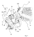
図1から図5において、本発明の第1の好適な実施形態に係る自転車のギアシフト装置、特に、リアギアシフト装置を符号10で示している。
In FIGS. 1 to 5, the bicycle gear shift device according to the first preferred embodiment of the present invention, particularly the rear gear shift device, is indicated by
リアギアシフト装置10は、自転車のフレーム12に装着されており(図1および図2)、自転車の後輪(図示せず)に結合されたスプロケットアセンブリ16の異なるスプロケット14間でチェーン(図示せず)を移動させる。
チェーンの移動は、作動リンク(actuation linkage)20に結合されたディレイラ18(またはチェーンガイド)の動きを介して行われる。
The rear
The movement of the chain is carried out via the movement of the derailleur 18 (or chain guide) coupled to the
ギアシフト装置10は、機械的に作動またはモータ駆動されることが可能である。添付の図面には、限定的でない実施例として、電動のギアシフト装置が示されており、ディレイラ18の動きは、適宜(典型的には、電気的に)駆動される駆動部材22を用いて実現される。駆動されると、作動リンク20は、ディレイラ18を移動させるために変形する。
The
作動リンク20は、(好ましくは、関節型平行四辺形の形状を有する)関節型四辺形リンクであり、自転車のフレーム12に回転可能に接続されるように構成された第1のボディ24と、ディレイラ18を支持するように構成された第2のボディ26と、第1のボディ24および第2のボディ26を接続する一対の関節ロッド28とを備える。このロッド28は、自転車のフレームに対する自身の相対位置を基準として、それぞれ「内側ロッド」および「外側ロッド」とも称される。
第2のボディ26およびディレイラ18の間にプリテンションばね(pre-tensioning spring)が配置されること自体は、従来的な方法でなされる。
The
The arrangement of the pre-tensioning spring between the
本願に図示された実施例において、駆動部材22は第1のボディ24内に収納され、作動リンク20の変形をコマンドして、関節型四辺形の対角線を伸長または短縮する。具体的に述べると、そうした対角線を伸長することによって、(より大径のスプロケット14に向かって)アップギアシフト動作が行われ、また逆に、対角線を短縮することによって、(より小径のスプロケット14に向かって)ダウンギアシフト動作が行われる。
In the embodiment illustrated in the present application, the
駆動部材22は、第1のボディ24に固定的に接続された(ケーブルおよび駆動部材22bから動力を得て、駆動される)電動モータ22aと、電動モータ22aによって回転駆動される伝動エレメント(motion transmission element)22cとを備える。例えば、動作伝達エレメント22cは、電動モータ22aの伝動シャフトによって形成される。
The
ギアシフト装置10は、作動リンク20を自転車のフレーム12に接続する接続部材30を備える。こうした接続部材30はフレーム12に固定される。
The
第1のボディ24は、回転軸Xにおいて接続部材30に回転可能に接続される。好ましくは、相互の位置の調節のために、接続部材30とフレーム12との間にいかなるエレメントも設けられていない。
The
具体的に述べると、本発明の第1の好適な実施形態において、接続部材30は、回転軸Xと同軸の第1の回転ピン31aを介して第1のボディ24に回転可能に接続され、かつ回転軸Xとは異なる取付軸Zに配置された第1の取付ねじ31bを介してフレーム12に固定されたブラケット31である(図2および図3)。好ましくは、取付軸Zは、(図1に示されるように)回転軸Xに実質的に平行である。
Specifically, in the first preferred embodiment of the present invention, the connecting
図3および図4に示されるように、第1の回転ピン31aは、周方向凹部31dに嵌合された弾性ワッシャ31cを介して接続部材30に装着される。好ましくは、弾性ワッシャ31cはオープンリング(open ring)のような形状である。
As shown in FIGS. 3 and 4, the first
ギアシフト装置10は、さらに、接続部材30と第1のボディ24との間で作用する係止装置(locking device)32を備える。
係止装置32は、接続部材30に対して回転軸Xを中心として第1のボディ24が移動自在である(図1、図3および図4に示された)第1の動作形態と、第1のボディ24が接続部材30に対して所定の角度方向位置に保持される(図2および図5に示された)第2の動作形態との間で移行するために、選択的に作動可能である。
The
In the
図2に示されるように、第2の動作形態においては、ギアシフト装置10は、図1に示されたギアシフト装置10の第1の通常動作の動作形態において占められる位置に対して後退した位置にある。これにより、ディレイラ18の上方プーリまたはスプロケット19aをスプロケットアセンブリ16の下方に離れたところに移動させることが可能であり、この上方プーリまたはスプロケット19aが移動されなければ、自転車のフレームから後輪を取り外す際の妨げとなるであろう。実際には、ディレイラ18の上方プーリ19aは移動され、自由に車輪を取り外したり、再び取り付けたりすることができる十分な空間をスプロケットアセンブリ16の下方に残す。
As shown in FIG. 2, in the second operation mode, the
係止装置32は、第1のボディ24上に形成された貫通キャビティ(through cavity)
36内のスライド軸Yに沿ってスライドするように構成されたピン34を備える。好ましくは、スライド軸Yは、(図1に示されるように)回転軸Xに対して実質的に平行である。
ピン34は、第1の動作形態から第2の動作形態への移行をコマンドするために作動される(好ましくは、ボタンのように構成された)作動端部34aを備える。
The locking
A
The
ピン34は、さらに、反対側の係止端部34bを備える。図2および図5に明瞭に示されるように、係止装置32が第2の動作形態にあるとき、係止端部34bは接続部材30の下面および背面に当接しており、これにより、第1のボディ24および接続部材30の間の相対的回転を防止する。したがって、このような動作形態において、係止端部34bは、作動端部34aが配置されている接続部材30の一方側とは反対の他方側に配置されている。具体的に述べると、作動端部34aは接続部材30の前側、すなわち、第1のボディ24に面している側に配置されており、係止端部34bは第1のボディ24に対して反対側を向いている他方の後側に配置されている。
The
本発明の当前記第1の好適な実施形態において、係止端部34bは、図4に示されるように、拡大ヘッド34dをその終端とするステム34cを備える。係止装置32が第2の動作形態にあるとき、ステム34cは、接続部材30の下面に当接しており、また、拡大ヘッド34dは接続部材30の背面に当接している。ピン34の係止端部34bのステム34cと接続部材30との間の当接は、接続部材30内に形成された成形収容座部30aにおいて生じる。このような成形収容座部30aは、接続部材30の下面から突出する突出部30bによって順次形成される凹部によって形成される。
In the first preferred embodiment of the present invention, the locking
図4に示されるように、係止装置32は、さらに、貫通キャビティ36内においてプレロードされた状態で収納された弾性エレメント38を備える。図4の限定的でない実施例の弾性エレメント38は、螺旋ばね(helical spring)である。弾性エレメント38は、作動端部34aと貫通キャビティ36内に形成された当接面36aとの間で作用する。
As shown in FIG. 4, the locking
さらに、図4に示されるように、係止装置32は、接続部材30と第1のボディ24との間に配置された弾性トーションエレメント40を備える。弾性トーションエレメント40は回転軸Xと同軸にある。図4の限定的でない実施例の弾性トーションエレメント40は、第1の回転ピン31aを中心として装着された螺旋トーションばねである。
Further, as shown in FIG. 4, the locking
接続部材30および第1のボディ24は、係止装置32が第1の動作形態にあるとき、接続部材30に対する第1のボディ24のエンドストップ角度方向位置を調節するように構成されたエンドストップ調節手段42を備える。
The connecting
図面に示された限定的でない実施例において、エンドストップ調節手段42は、第1のボディ24と一体形成されたねじ着座部(threaded seat)に螺合され、かつ接続部材30と固定的に結合された当接エレメント42b上に当接する端部を有する調節ねじ42aを備える。代替的に、変更された実施形態(図示せず)において、調節ねじ42aが接続部材30と一体形成されたねじ着座部に螺合され、かつ当接エレメント42bが第1のボディ24と固定的に結合される構成とすることも可能である。
In a non-limiting embodiment shown in the drawings, the end stop adjusting means 42 is screwed into a threaded seat integrally formed with the
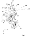
図6には、本発明に係る自転車のギアシフト装置10の第2の好適な実施形態が示されている。
図6の自転車のギアシフト装置10の構成品のうち、図1から図5の自転車のギアシフト装置10の構成品と類似または機能的に同等のものは同一の符号で示されており、それらの説明については上記を参照されたい。
図6の自転車のギアシフト装置10は、実質的に係止装置32のピン34のみにおいて、特に、ピン34の係止端部34bのみにおいて、図1から図5の自転車のギアシフト装置10と相異する。
FIG. 6 shows a second preferred embodiment of the bicycle
Among the components of the bicycle
The bicycle
この第2の好適な実施形態において、係止端部34bは、それぞれの弾性ワッシャ134dが収納される周方向凹部134eを備えたステム134cを備える。係止装置32が第2の動作形態にあるとき、ステム134cは接続部材30の下面に当接しており、また、弾性ワッシャ134dは接続部材30の背面に当接している。好ましくは、弾性ワッシャ134dはオープンリングのような形状である。
In this second preferred embodiment, the locking
よって、図6の自転車のギアシフト装置10のピン34の弾性ワッシャ134dは、図1から図5の自転車のギアシフト装置10のピン34の拡大ヘッド34dが果たす機能と同一の機能を果たす。
Therefore, the
図7から図10には、本発明に係る自転車のギアシフト装置の第3の好適な実施形態が示されている。
図7から図10の自転車のギアシフト装置10の構成品のうち、図1から図5の自転車のギアシフト装置10の構成品と類似または機能的に同等のものは同一の符号で示されており、それらの説明については上記を参照されたい。
図7から図10の自転車のギアシフト装置10は、実質的に、接続部材30がブラケット31ではなくブッシュ231である点のみにおいて、図1から図5の自転車のギアシフト装置10と相異する。
7 to 10 show a third preferred embodiment of the bicycle gear shift device according to the present invention.
Among the components of the bicycle
The bicycle
このようなブッシュ231は、回転軸Xと同軸の第2の回転ピン231aを介して第1のボディ24に回転可能に接続され、かつ第2の取付ねじ(図示せず)を介してフレームに固定されている。この第2の取付ねじが、第2の回転ピン231aの自由端部に一体化されていることが好ましい。第2の取付ねじは第2の回転ピン231aと同軸であり、したがって、回転軸Xと同軸である。
Such a
走行時において、自転車のギアシフト装置10は、通常、(図1、図3、図4、図7および図9に示される)第1の動作形態にある。この動作形態において、第1のボディ24は接続部材30に対して回転軸Xを中心として移動自在であり、これにより、自転車の後輪と結合されたスプロケットアセンブリ16の異なるスプロケット14間でチェーンを移動させることが可能である。
When traveling, the bicycle
自転車の後輪の交換を容易にするのに適した位置にディレイラ18を配置することができるように、係止装置32は、(図2、図5、図8および図10に示される)第2の動作形態へと移行するために作動され、第1のボディ24は接続部材30に対して所定の角度方向位置に配置され、かつ保持される。
The locking
既に述べたように、第2の動作形態において、ギアシフト装置10は、(通常、自転車の後輪がその座部から出ないようにする)ディレイラ18の上方プーリ19aが移動されて、スプロケットアセンブリ16の下に実質的に自由な空間を残す位置にある。
As already mentioned, in the second mode of operation, the
係止装置32は、主に、チェーンの振動を安定させるためのクラッチが設けられたギアシフト装置において特に有益である。そうしたクラッチが、後輪を取り外す際にさらなる障害となるからである。
The locking
第1のボディ24は、接続部材30に対する所定の角度方向位置に達するまで、一方の回転方向に(図1および図7を基準として、時計回りに)回転軸Xを中心として回転させられ、これにより作動端部34aがプッシュされて、ピン34の係止端部34bを接続部材30へと、そして接続部材30を超えて移動させることが可能である。この時点において、第1のボディ24および作動端部34aがリリースされ、接続部材30の成形収納座部30aにおける接続部材30の下面と、係止端部34bのステム34c、134cとの間の当接、および、ピン34上の弾性エレメント38によって加えられる弾性戻し作用の効果によって係止端部34bと接続部材30の背面との間の当接が実現する。これにより、上記の角度方向位置におけるギアシフト装置10の係止が実現する。実際のところ、こうした位置において、第1のボディ24は反対側の回転方向に(図1および図7を基準として、反時計回りに)回転不能である。
The
第1のボディ24の回転時に第2の動作形態に到達するために、ディレイラ18はチェーンの牽引によって延びて、特に、ディレイラ18の上方プーリ19aは、後輪の取り出しのためにスプロケットアセンブリ16の下の通路を空ける。
The
ギアシフト装置10を第1の動作形態に戻すためには、第1のボディ24を上記の回転方向に(図1および図7を基準として、時計回りに)僅かに回転させるだけで十分であり、これにより、ピン34の係止端部34bは、ピン34上の弾性エレメント38によって加えられる弾性戻り作用によって接続部材30からリリースされる。その後、ギアシフト装置10は、反対側の回転方向に(図1および図7を基準として、反時計回りに)第1のボディ24を回転させることによって、第1の動作形態に戻る。
In order to return the
係止装置32が「解除」されているとき、ディレイラ18に作用するチェーンによって加えられる牽引により、第1のボディ24は、第1の動作形態になり、かつ接続部材30に対して可動のエンドストップ回転角度方向位置を取る。エンドストップ調節手段42は、係止装置32が第1の動作形態にあるとき、接続部材30に対する第1のボディ24のエンドストップ角度方向位置を調節する機能を有する。
When the
接続部材30と第1のボディ24との間に弾性トーションエレメント40が設けられた場合、第1のボディ24を上記の回転方向に(図1および図7を基準として、時計回りに)回転させる際に弾性トーションエレメント40に負荷が加わり、これにより、第2の動作形態を極めて安定的に保つことが可能である。
When the
当然ながら、当業者であれば、特定の要件や付随の要件を満足するために、これまでに記載した自転車のギアシフト装置に様々な変更や変形を施すことが考えられる。いずれにせよ、そのような変更および変形は全て、添付の特許請求の範囲によって定められる本発明の保護範囲に包含される。 Of course, one of ordinary skill in the art can make various changes and modifications to the bicycle gear shift devices described above in order to satisfy specific requirements and incidental requirements. In any case, all such changes and modifications are within the scope of the invention as defined by the appended claims.
特に、図7から図10の第3の好適な実施形態において、係止端部34bが図6の第2の好適な実施形態において説明された型のものである場合、すなわち、それぞれの弾性ワッシャ134dが設けられたピン34である場合、ピン34を用いることが可能である。
In particular, in the third preferred embodiment of FIGS. 7 to 10, when the locking
さらに、上記の全ての好適な実施形態において、貫通キャビティ36は、接続部材30上に形成することも可能であり、この場合、上記の作動と明らかに類似した作動によって、ピン34の係止端部34bは第1のボディ24に当接するであろう。
以下、本発明に含まれる態様を記す。
〔態様1〕自転車のギアシフト装置(10)において、
‐前記ギアシフト装置(10)のディレイラ(18)を動かすために変形するように構成された作動リンク(20)であって、自転車のフレーム(12)に回転可能に接続されるように構成された第1のボディ(24)と、前記ギアシフト装置の前記ディレイラ(18)を支持するように構成された第2のボディ(26)と、前記第1のボディ(24)および前記第2のボディ(26)を接続する一対の関節ロッド(28)とを備える、作動リンク(20)と、
‐前記作動リンク(20)を前記自転車のフレーム(12)に接続する接続部材(30)であって、回転軸(X)において前記第1のボディ(24)を回転可能に接続するために、前記フレーム(12)に固定されるように構成されている、接続部材(30)と、
‐前記接続部材(30)と前記第1のボディ(24)との間で作用し、且つ前記第1のボディ(24)が回転軸(X)を中心として前記接続部材(30)に対して移動自在である第1の動作形態と、前記第1のボディ(24)が前記接続部材(30)に対して所定の角度方向位置に保持される第2の動作形態と、の間で移行するように選択的に作動可能である係止装置(32)と、
を備える、ギアシフト装置において、
前記係止装置(32)は、前記第1のボディ(24)に形成された貫通キャビティ(36)内のスライド軸(Y)に沿ってスライド可能なピン(34)を備え、前記ピン(34)は、第1の動作形態から第2の動作形態への移行をコマンドするために作動される作動端部(34a)と、前記係止装置(32)が前記第2の動作形態にあるとき、前記接続部材(30)に当接することで前記第1のボディ(24)と前記接続部材(30)の間の相対的な回転を防止する、前記作動端部(34a)とは反対側の係止端部(34b)とを備え、前記係止装置(32)が第2の動作形態にあるとき、前記作動端部(34a)は前記接続部材(30)の一方側に配置され、前記係止端部(34b)は前記接続部材(30)の他方側に配置されることを特徴とする、ギアシフト装置。
〔態様2〕態様1に記載のギアシフト装置(10)において、前記係止装置(32)が第2の動作形態にあるとき、前記係止端部(34b)は前記接続部材(30)の下面および背面に当接している、ギアシフト装置。
〔態様3〕態様2に記載のギアシフト装置(10)において、前記係止端部(34b)は、拡大ヘッド(34d)をその終端とするステム(34c)を備え、前記係止装置(32)が第2の動作形態にあるとき、前記ステム(34c)は前記接続部材(30)の前記下面に当接し、かつ前記拡大ヘッド(34d)は前記接続部材(30)の前記背面に当接している、ギアシフト装置。
〔態様4〕態様2に記載のギアシフト装置(10)において、前記係止端部(34b)は、弾性ワッシャ(134d)が収納される周方向凹部(134e)を備えるステム(134c)を備え、前記係止装置(32)が第2の動作形態にあるとき、前記ステム(134c)は前記接続部材(30)の前記下面に当接し、かつ前記弾性ワッシャ(134d)は前記接続部材(30)の前記背面に当接している、ギアシフト装置。
〔態様5〕態様1から4のいずれか一態様に記載のギアシフト装置(10)において、前記係止装置(32)は、前記貫通キャビティ(36)内にプレロードされた状態で収納され、かつ前記作動端部(34a)と前記貫通キャビティ(36)内に形成された当接面(36a)との間で作用する弾性エレメント(38)を備える、ギアシフト装置。
〔態様6〕態様1から5のいずれか一態様に記載のギアシフト装置(10)において、前記接続部材(30)は、回転軸(X)と同軸の第1の回転ピン(31a)を介して前記第1のボディ(24)に回転可能に接続され、かつ回転軸(X)とは異なる取付軸(Z)に配置された第1の取付ねじ(31b)を介して前記フレーム(12)に固定されるように構成されたブラケット(31)である、ギアシフト装置。
〔態様7〕態様1から5のいずれか一態様に記載のギアシフト装置(10)において、前記接続部材(30)は、回転軸(X)と同軸の第2の回転ピン(231a)を介して前記第1のボディ(24)に回転可能に接続され、かつ前記第2の回転ピン(231a)の自由端部に一体化された第2の取付ねじを介して前記フレーム(12)に固定されるように構成されたブッシュ(231)である、ギアシフト装置。
〔態様8〕態様1から7のいずれか一態様に記載のギアシフト装置(10)において、前記接続部材(30)および前記第1のボディ(24)は、前記係止装置(32)が第1の動作形態にあるとき、前記接続部材(30)に対する前記第1のボディ(24)のエンドストップ角度方向位置を調節するように構成されたエンドストップ調節手段(42)を備える、ギアシフト装置。
〔態様9〕態様8に記載のギアシフト装置(10)において、前記エンドストップ調節手段(42)は、前記接続部材(30)および前記第1のボディ(24)の一方と一体形成されたねじ孔を有する着座部にねじ込まれ、かつ前記接続部材(30)および前記第1のボディ(24)の他方と結合固定された当接エレメント(42b)上に当接する端部を有する調節ねじ(42a)を備える、ギアシフト装置。
〔態様10〕態様1から9のいずれか一態様に記載のギアシフト装置(10)において、前記接続部材(30)および前記第1のボディ(24)の間に弾性トーションエレメント(40)が設けられ、前記弾性トーションエレメント(40)は回転軸(X)と同軸にある、ギアシフト装置。
Further, in all the preferred embodiments described above, the through
Hereinafter, aspects included in the present invention will be described.
[Aspect 1] In the bicycle gear shift device (10),
-A working link (20) configured to deform to move the derailleur (18) of the gearshifting device (10) and rotatably connected to the bicycle frame (12). A first body (24), a second body (26) configured to support the derailleur (18) of the gear shift device, the first body (24), and the second body ( An actuating link (20) comprising a pair of joint rods (28) connecting the 26).
-A connecting member (30) that connects the actuating link (20) to the bicycle frame (12) to rotatably connect the first body (24) on a rotation shaft (X). A connecting member (30) configured to be fixed to the frame (12) and
-Acting between the connecting member (30) and the first body (24), and the first body (24) with respect to the connecting member (30) about the rotation axis (X). There is a transition between a first mode of motion that is movable and a second mode of motion in which the first body (24) is held at a predetermined angular position with respect to the connecting member (30). With a locking device (32) that can be selectively operated as
In a gear shift device equipped with
The locking device (32) comprises a pin (34) slidable along a slide axis (Y) in a through cavity (36) formed in the first body (24). ) Is when the operating end portion (34a) operated to command the transition from the first operating mode to the second operating mode and the locking device (32) are in the second operating mode. , On the side opposite to the working end (34a), which prevents relative rotation between the first body (24) and the connecting member (30) by abutting on the connecting member (30). When the locking end (34b) is provided and the locking device (32) is in the second mode of operation, the actuating end (34a) is disposed on one side of the connecting member (30). A gear shift device, characterized in that the locking end (34b) is arranged on the other side of the connecting member (30).
[Aspect 2] In the gear shift device (10) according to the first aspect, when the locking device (32) is in the second operating mode, the locking end portion (34b) is the lower surface of the connecting member (30). And a gear shift device that is in contact with the back.
[Aspect 3] In the gear shift device (10) according to the second aspect, the locking end (34b) includes a stem (34c) whose end is an expansion head (34d), and the locking device (32) Is in the second mode of operation, the stem (34c) is in contact with the lower surface of the connecting member (30), and the expansion head (34d) is in contact with the back surface of the connecting member (30). There is a gear shift device.
[Aspect 4] In the gear shift device (10) according to the second aspect, the locking end portion (34b) includes a stem (134c) including a circumferential recess (134e) in which an elastic washer (134d) is housed. When the locking device (32) is in the second mode of operation, the stem (134c) is in contact with the lower surface of the connecting member (30), and the elastic washer (134d) is in contact with the connecting member (30). A gear shift device that is in contact with the back surface of the.
[Aspect 5] In the gear shift device (10) according to any one of aspects 1 to 4, the locking device (32) is housed in the through cavity (36) in a preloaded state, and said. A gear shift device comprising an elastic element (38) that acts between an actuating end (34a) and an abutting surface (36a) formed within the through cavity (36).
[Aspect 6] In the gear shift device (10) according to any one of aspects 1 to 5, the connecting member (30) is via a first rotating pin (31a) coaxial with the rotating shaft (X). To the frame (12) via a first mounting screw (31b) rotatably connected to the first body (24) and arranged on a mounting shaft (Z) different from the rotating shaft (X). A gear shift device, which is a bracket (31) configured to be fixed.
[Aspect 7] In the gear shift device (10) according to any one of aspects 1 to 5, the connecting member (30) is via a second rotating pin (231a) coaxial with the rotating shaft (X). It is rotatably connected to the first body (24) and fixed to the frame (12) via a second mounting screw integrated with the free end of the second rotating pin (231a). A gear shift device, which is a bush (231) configured to be such.
[Aspect 8] In the gear shift device (10) according to any one of aspects 1 to 7, the locking device (32) is the first of the connecting member (30) and the first body (24). A gear shift device comprising an end stop adjusting means (42) configured to adjust the end stop angular direction position of the first body (24) with respect to the connecting member (30) when in the mode of operation.
[Aspect 9] In the gear shift device (10) according to the eighth aspect, the end stop adjusting means (42) is a screw hole integrally formed with one of the connecting member (30) and the first body (24). Adjusting screw (42a) having an end that is screwed into a seating portion having the A gear shift device.
[Aspect 10] In the gear shift device (10) according to any one of aspects 1 to 9, an elastic torsion element (40) is provided between the connecting member (30) and the first body (24). , The elastic torsion element (40) is a gear shift device coaxial with the rotation axis (X).
Claims (7)
‐前記ギアシフト装置(10)のディレイラ(18)を動かすために変形するように構成された作動リンク(20)であって、自転車のフレーム(12)に回転可能に接続されるように構成された第1のボディ(24)と、前記ギアシフト装置の前記ディレイラ(18)を支持するように構成された第2のボディ(26)と、前記第1のボディ(24)および前記第2のボディ(26)を接続する一対の関節ロッド(28)とを備える、作動リンク(20)と、
‐前記作動リンク(20)を前記自転車のフレーム(12)に接続する接続部材(30)であって、回転軸(X)において前記第1のボディ(24)を回転可能に接続するために、前記フレーム(12)に固定されるように構成されている、接続部材(30)と、
‐前記接続部材(30)と前記第1のボディ(24)との間で作用し、且つ前記第1のボディ(24)が回転軸(X)を中心として前記接続部材(30)に対して移動自在である第1の動作形態と、前記第1のボディ(24)が前記接続部材(30)に対して所定の角度方向位置に保持される第2の動作形態と、の間で移行するように選択的に作動可能である係止装置(32)と、を備え、
前記係止装置(32)は、前記第1のボディ(24)に形成された貫通キャビティ(36)内のスライド軸(Y)に沿ってスライド可能な、単一のピン(34)を備え、前記ピン(34)は、第1の動作形態から第2の動作形態への移行をコマンドするために作動される作動端部(34a)と、前記係止装置(32)が前記第2の動作形態にあるとき、前記接続部材(30)に当接することで前記第1のボディ(24)と前記接続部材(30)の間の相対的な回転を防止する、前記作動端部(34a)とは反対側の係止端部(34b)とを備え、前記係止装置(32)が第2の動作形態にあるとき、前記作動端部(34a)は前記接続部材(30)の一方側に配置され、前記係止端部(34b)は前記接続部材(30)の他方側に配置され、
前記係止装置(32)が第2の動作形態にあるとき、前記係止端部(34b)は前記接続部材(30)の下面および背面に当接しており、
前記係止端部(34b)は、拡大ヘッド(34d)をその終端とする、または、弾性ワッシャ(134d)が収納されている周方向凹部(134e)を備える、ステム(34c、134c)を備え、
前記係止装置(32)が第2の動作形態にあるとき、前記ステム(34c、134c)は前記接続部材(30)の前記下面に当接し、かつ前記拡大ヘッド(34d)または前記弾性ワッシャ(134d)は前記接続部材(30)の前記背面に当接しており、
前記ステム(34c、134c)と前記接続部材(30)の下面との間の当接は、前記接続部材(30)の下面に形成されている成形収容座部(30a)において生じることを特徴とするギアシフト装置。 In the bicycle gear shift device (10)
-A working link (20) configured to deform to move the derailleur (18) of the gearshifting device (10) and rotatably connected to the bicycle frame (12). A first body (24), a second body (26) configured to support the derailleur (18) of the gear shift device, the first body (24), and the second body ( An actuating link (20) comprising a pair of joint rods (28) connecting the 26).
-A connecting member (30) that connects the actuating link (20) to the bicycle frame (12) to rotatably connect the first body (24) on a rotation shaft (X). A connecting member (30) configured to be fixed to the frame (12) and
-Acting between the connecting member (30) and the first body (24), and the first body (24) with respect to the connecting member (30) about the rotation axis (X). There is a transition between a first mode of motion that is movable and a second mode of motion in which the first body (24) is held at a predetermined angular position with respect to the connecting member (30). With a locking device (32), which can be selectively operated as described above.
The locking device (32) comprises a single pin (34) that is slidable along a slide axis (Y) within the through cavity (36) formed in the first body (24). The pin (34) has an operating end (34a) that is activated to command a transition from the first operating mode to the second operating mode, and the locking device (32) has the second operation. With the working end (34a), which, when in the form, abuts on the connecting member (30) to prevent relative rotation between the first body (24) and the connecting member (30). Is provided with a locking end (34b) on the opposite side, and when the locking device (32) is in the second mode of operation, the actuating end (34a) is on one side of the connecting member (30). Arranged, the locking end (34b) is disposed on the other side of the connecting member (30).
When the locking device (32) is in the second operating mode, the locking end (34b) is in contact with the lower surface and the back surface of the connecting member (30).
The locking end (34b) includes stems (34c, 134c) ending in an expansion head (34d) or having a circumferential recess (134e) in which an elastic washer (134d) is housed. ,
When the locking device (32) is in the second mode of operation, the stems (34c, 134c) are in contact with the lower surface of the connecting member (30) and the expansion head (34d) or the elastic washer ( 134d) is in contact with the back surface of the connecting member (30).
The contact between the stem (34c, 134c) and the lower surface of the connecting member (30) is characterized in that it occurs in the molded accommodating seat portion (30a) formed on the lower surface of the connecting member (30). Gear shift device.
Applications Claiming Priority (2)
| Application Number | Priority Date | Filing Date | Title |
|---|---|---|---|
| IT102016000076517 | 2016-07-21 | ||
| IT102016000076517A IT201600076517A1 (en) | 2016-07-21 | 2016-07-21 | BICYCLE CHANGE |
Publications (3)
| Publication Number | Publication Date |
|---|---|
| JP2018058574A JP2018058574A (en) | 2018-04-12 |
| JP2018058574A5 JP2018058574A5 (en) | 2020-06-25 |
| JP6814705B2 true JP6814705B2 (en) | 2021-01-20 |
Family
ID=57610124
Family Applications (1)
| Application Number | Title | Priority Date | Filing Date |
|---|---|---|---|
| JP2017139850A Active JP6814705B2 (en) | 2016-07-21 | 2017-07-19 | Bicycle gear shift device |
Country Status (6)
| Country | Link |
|---|---|
| US (1) | US10486769B2 (en) |
| EP (1) | EP3272634B1 (en) |
| JP (1) | JP6814705B2 (en) |
| CN (1) | CN107640277B (en) |
| IT (1) | IT201600076517A1 (en) |
| TW (1) | TWI730144B (en) |
Families Citing this family (3)
| Publication number | Priority date | Publication date | Assignee | Title |
|---|---|---|---|---|
| DE102018001253A1 (en) * | 2017-03-20 | 2018-09-20 | Sram Deutschland Gmbh | Rear derailleur for coaxial mounting |
| TWI680911B (en) * | 2018-08-22 | 2020-01-01 | 彥豪金屬工業股份有限公司 | Bicycle rear derailleur |
| DE102020000827A1 (en) * | 2019-04-25 | 2020-10-29 | Sram Deutschland Gmbh | Electromechanical switching mechanism for coaxial assembly |
Family Cites Families (27)
| Publication number | Priority date | Publication date | Assignee | Title |
|---|---|---|---|---|
| US3964330A (en) * | 1974-11-08 | 1976-06-22 | Maeda Industries, Ltd. | Chain guide connector device for use in bicycle derailleurs |
| FR2427243A1 (en) * | 1978-06-01 | 1979-12-28 | Huret Roger | CYCLE DERAILLEUR |
| IT1132005B (en) * | 1979-08-08 | 1986-06-25 | Huret & Fils | FRONT DERAILLEUR FOR BICYCLE |
| JPH0226794Y2 (en) * | 1985-06-17 | 1990-07-20 | ||
| JP2606242Y2 (en) * | 1993-02-03 | 2000-10-10 | 株式会社シマノ | Rear derailleur bracket for bicycle |
| US5498211A (en) * | 1994-11-29 | 1996-03-12 | Hsu; Yi-Hsung | Bicycle speed change mechanisms |
| US5961409A (en) * | 1996-12-26 | 1999-10-05 | Shimano, Inc. | Rear derailleur for a bicycle |
| US5931753A (en) * | 1998-02-09 | 1999-08-03 | Shimano, Inc. | Rear deraileur with shock absorber |
| EP1107902B1 (en) * | 1998-08-26 | 2003-12-03 | Shimano Inc. | Rear changer device for bicycle |
| US6287228B1 (en) * | 1999-11-12 | 2001-09-11 | Shimano, Inc. | Rear derailleur with cable guide roller |
| JP3708515B2 (en) | 2002-10-30 | 2005-10-19 | 株式会社シマノ | Bicycle rear derailleur |
| JP3667312B2 (en) * | 2002-10-30 | 2005-07-06 | 株式会社シマノ | Bicycle rear derailleur |
| US8277346B2 (en) * | 2006-02-28 | 2012-10-02 | Shimano, Inc. | Low profile rear derailleur |
| US20080051237A1 (en) * | 2006-08-24 | 2008-02-28 | Shimano Inc. | Bicycle rear derailleur |
| US7905804B2 (en) * | 2006-09-08 | 2011-03-15 | Shimano Inc. | Bicycle derailleur |
| US20080081716A1 (en) * | 2006-09-25 | 2008-04-03 | Shimano Inc. | Bicycle rear derailleur |
| US7722488B2 (en) * | 2006-09-25 | 2010-05-25 | Shimano Inc. | Bicycle rear derailleur |
| US8137223B2 (en) * | 2007-05-16 | 2012-03-20 | Shimano Inc. | Bicycle rear derailleur |
| US7942767B2 (en) * | 2007-12-19 | 2011-05-17 | Shimano, Inc. | Bicycle derailleur with multiple mounting adjustments |
| US7963870B2 (en) * | 2008-05-01 | 2011-06-21 | Shimano Inc. | Bicycle rear derailleur |
| US8142312B2 (en) * | 2008-07-02 | 2012-03-27 | Shimano Inc. | Bicycle rear derailleur |
| DE102011118912A1 (en) * | 2011-11-18 | 2013-05-23 | Sram Deutschland Gmbh | A derailleur device for a bicycle circuit, in particular rear derailleur device |
| US9334016B2 (en) * | 2012-07-13 | 2016-05-10 | Shimano Inc. | Bicycle rear derailleur |
| ITMI20131825A1 (en) * | 2013-11-04 | 2015-05-05 | Campagnolo Srl | MOTORIZED DRIVE DERAILLEUR FOR A BICYCLE CHANGE |
| ITMI20131949A1 (en) * | 2013-11-22 | 2015-05-23 | Campagnolo Srl | ASSEMBLY DEVICE FOR A FRONT DERAILLEUR OF A REAR TRANSMISSION ON A BICYCLE FRAME |
| DE102014225036A1 (en) * | 2013-12-23 | 2015-06-25 | Sram Deutschland Gmbh | Bicycle decanter with friction damping |
| ITMI20142069A1 (en) * | 2014-12-02 | 2016-06-02 | Campagnolo Srl | DERAILLEUR OF A BICYCLE CHANGE AND METHOD OF ELECTRONICALLY CONTROL OF A BICYCLE CHANGE |
-
2016
- 2016-07-21 IT IT102016000076517A patent/IT201600076517A1/en unknown
-
2017
- 2017-07-11 EP EP17180674.8A patent/EP3272634B1/en active Active
- 2017-07-12 TW TW106123281A patent/TWI730144B/en active
- 2017-07-17 US US15/651,495 patent/US10486769B2/en active Active
- 2017-07-19 JP JP2017139850A patent/JP6814705B2/en active Active
- 2017-07-21 CN CN201710601647.3A patent/CN107640277B/en active Active
Also Published As
| Publication number | Publication date |
|---|---|
| IT201600076517A1 (en) | 2018-01-21 |
| JP2018058574A (en) | 2018-04-12 |
| CN107640277B (en) | 2020-12-15 |
| US10486769B2 (en) | 2019-11-26 |
| US20180022417A1 (en) | 2018-01-25 |
| EP3272634B1 (en) | 2019-11-06 |
| EP3272634A1 (en) | 2018-01-24 |
| TW201803770A (en) | 2018-02-01 |
| CN107640277A (en) | 2018-01-30 |
| TWI730144B (en) | 2021-06-11 |
Similar Documents
| Publication | Publication Date | Title |
|---|---|---|
| JP6814705B2 (en) | Bicycle gear shift device | |
| ES2226067T3 (en) | INTERLOCK SYSTEM OF THE PARKING POSITION. | |
| CN106043573B (en) | Bicycle control device for operating a bicycle component | |
| FR2541225A1 (en) | DERAILLEUR FOR A BICYCLE | |
| TWI729124B (en) | Actuator device for a bicycle gearshift and respective bicycle gearshift | |
| JP6999438B2 (en) | Bicycle front derailleur | |
| JP2018058574A5 (en) | ||
| EP4177425B1 (en) | External opening control device for a motor vehicle opening | |
| FR2601628A1 (en) | ADVANCE MECHANISM FOR A WRITING INSTRUMENT | |
| US7097260B2 (en) | Parking brake for a tractor | |
| EP2659076B1 (en) | Control device for a vehicle door locking system | |
| EP1861636B1 (en) | Device for offset control of an automatic gearbox allowing manual control | |
| JP4750503B2 (en) | Selector device for transmission | |
| JP2006345764A (en) | Riding type rice transplanter | |
| FR3120038A1 (en) | Foot pedal for motor vehicle pedal brake control. | |
| JP5796077B2 (en) | Shift device having excessive shift prevention mechanism | |
| EP4206430A1 (en) | External opening control device for a motor vehicle wing | |
| FR2644861A1 (en) | Automatic coupling of two shafts, one driving and one driven | |
| FR2918006A1 (en) | Seat height adjustment mechanism for motor vehicle, has locking element engaged with toothed element, and arm for rotating locking element for disengaging locking element from toothed element to place connection elements in unlocked state | |
| FR3077358A1 (en) | MECHANICAL LOCKING DEVICE OF A TRANSMISSION SHAFT IN PARKING POSITION | |
| BE638537A (en) | ||
| FR2873735A1 (en) | Opening e.g. rear quarter window, locking device for motor vehicle, has elastic return unit inserted between rear zone of locking unit`s movable inner hook and fixed part of operating lever to obtain permanent elastic return of locking unit | |
| BE360410A (en) | ||
| FR3056944A1 (en) | JOINT MECHANISM FOR A VEHICLE SEAT AND SEAT COMPRISING SUCH A JOINT MECHANISM | |
| FR3047960A1 (en) | MOTOR VEHICLE EQUIPPED WITH A BRACKET OF A STEERING WHEEL WITH A LEVER FOR SECURE ADJUSTMENT |
Legal Events
| Date | Code | Title | Description |
|---|---|---|---|
| AA79 | Non-delivery of priority document |
Free format text: JAPANESE INTERMEDIATE CODE: A24379 Effective date: 20171128 |
|
| A521 | Request for written amendment filed |
Free format text: JAPANESE INTERMEDIATE CODE: A523 Effective date: 20200428 |
|
| A621 | Written request for application examination |
Free format text: JAPANESE INTERMEDIATE CODE: A621 Effective date: 20200428 |
|
| A871 | Explanation of circumstances concerning accelerated examination |
Free format text: JAPANESE INTERMEDIATE CODE: A871 Effective date: 20200428 |
|
| A975 | Report on accelerated examination |
Free format text: JAPANESE INTERMEDIATE CODE: A971005 Effective date: 20200623 |
|
| A131 | Notification of reasons for refusal |
Free format text: JAPANESE INTERMEDIATE CODE: A131 Effective date: 20200721 |
|
| A521 | Request for written amendment filed |
Free format text: JAPANESE INTERMEDIATE CODE: A523 Effective date: 20201019 |
|
| TRDD | Decision of grant or rejection written | ||
| A01 | Written decision to grant a patent or to grant a registration (utility model) |
Free format text: JAPANESE INTERMEDIATE CODE: A01 Effective date: 20201124 |
|
| A61 | First payment of annual fees (during grant procedure) |
Free format text: JAPANESE INTERMEDIATE CODE: A61 Effective date: 20201221 |
|
| R150 | Certificate of patent or registration of utility model |
Ref document number: 6814705 Country of ref document: JP Free format text: JAPANESE INTERMEDIATE CODE: R150 |
|
| R250 | Receipt of annual fees |
Free format text: JAPANESE INTERMEDIATE CODE: R250 |