CN107531232B - Motor device - Google Patents
Motor device Download PDFInfo
- Publication number
- CN107531232B CN107531232B CN201680020380.2A CN201680020380A CN107531232B CN 107531232 B CN107531232 B CN 107531232B CN 201680020380 A CN201680020380 A CN 201680020380A CN 107531232 B CN107531232 B CN 107531232B
- Authority
- CN
- China
- Prior art keywords
- phase
- motor
- mode
- windings
- internal combustion
- Prior art date
- Legal status (The legal status is an assumption and is not a legal conclusion. Google has not performed a legal analysis and makes no representation as to the accuracy of the status listed.)
- Active
Links
Images


Classifications
-
- B—PERFORMING OPERATIONS; TRANSPORTING
- B60—VEHICLES IN GENERAL
- B60W—CONJOINT CONTROL OF VEHICLE SUB-UNITS OF DIFFERENT TYPE OR DIFFERENT FUNCTION; CONTROL SYSTEMS SPECIALLY ADAPTED FOR HYBRID VEHICLES; ROAD VEHICLE DRIVE CONTROL SYSTEMS FOR PURPOSES NOT RELATED TO THE CONTROL OF A PARTICULAR SUB-UNIT
- B60W10/00—Conjoint control of vehicle sub-units of different type or different function
- B60W10/04—Conjoint control of vehicle sub-units of different type or different function including control of propulsion units
- B60W10/08—Conjoint control of vehicle sub-units of different type or different function including control of propulsion units including control of electric propulsion units, e.g. motors or generators
-
- B—PERFORMING OPERATIONS; TRANSPORTING
- B60—VEHICLES IN GENERAL
- B60W—CONJOINT CONTROL OF VEHICLE SUB-UNITS OF DIFFERENT TYPE OR DIFFERENT FUNCTION; CONTROL SYSTEMS SPECIALLY ADAPTED FOR HYBRID VEHICLES; ROAD VEHICLE DRIVE CONTROL SYSTEMS FOR PURPOSES NOT RELATED TO THE CONTROL OF A PARTICULAR SUB-UNIT
- B60W20/00—Control systems specially adapted for hybrid vehicles
-
- F—MECHANICAL ENGINEERING; LIGHTING; HEATING; WEAPONS; BLASTING
- F02—COMBUSTION ENGINES; HOT-GAS OR COMBUSTION-PRODUCT ENGINE PLANTS
- F02N—STARTING OF COMBUSTION ENGINES; STARTING AIDS FOR SUCH ENGINES, NOT OTHERWISE PROVIDED FOR
- F02N11/00—Starting of engines by means of electric motors
- F02N11/04—Starting of engines by means of electric motors the motors being associated with current generators
-
- F—MECHANICAL ENGINEERING; LIGHTING; HEATING; WEAPONS; BLASTING
- F02—COMBUSTION ENGINES; HOT-GAS OR COMBUSTION-PRODUCT ENGINE PLANTS
- F02N—STARTING OF COMBUSTION ENGINES; STARTING AIDS FOR SUCH ENGINES, NOT OTHERWISE PROVIDED FOR
- F02N11/00—Starting of engines by means of electric motors
- F02N11/08—Circuits or control means specially adapted for starting of engines
-
- H—ELECTRICITY
- H02—GENERATION; CONVERSION OR DISTRIBUTION OF ELECTRIC POWER
- H02P—CONTROL OR REGULATION OF ELECTRIC MOTORS, ELECTRIC GENERATORS OR DYNAMO-ELECTRIC CONVERTERS; CONTROLLING TRANSFORMERS, REACTORS OR CHOKE COILS
- H02P27/00—Arrangements or methods for the control of AC motors characterised by the kind of supply voltage
- H02P27/04—Arrangements or methods for the control of AC motors characterised by the kind of supply voltage using variable-frequency supply voltage, e.g. inverter or converter supply voltage
- H02P27/06—Arrangements or methods for the control of AC motors characterised by the kind of supply voltage using variable-frequency supply voltage, e.g. inverter or converter supply voltage using dc to ac converters or inverters
-
- Y—GENERAL TAGGING OF NEW TECHNOLOGICAL DEVELOPMENTS; GENERAL TAGGING OF CROSS-SECTIONAL TECHNOLOGIES SPANNING OVER SEVERAL SECTIONS OF THE IPC; TECHNICAL SUBJECTS COVERED BY FORMER USPC CROSS-REFERENCE ART COLLECTIONS [XRACs] AND DIGESTS
- Y02—TECHNOLOGIES OR APPLICATIONS FOR MITIGATION OR ADAPTATION AGAINST CLIMATE CHANGE
- Y02T—CLIMATE CHANGE MITIGATION TECHNOLOGIES RELATED TO TRANSPORTATION
- Y02T10/00—Road transport of goods or passengers
- Y02T10/10—Internal combustion engine [ICE] based vehicles
- Y02T10/40—Engine management systems
Landscapes
- Engineering & Computer Science (AREA)
- Chemical & Material Sciences (AREA)
- Combustion & Propulsion (AREA)
- Mechanical Engineering (AREA)
- Transportation (AREA)
- General Engineering & Computer Science (AREA)
- Power Engineering (AREA)
- Automation & Control Theory (AREA)
- Control Of Ac Motors In General (AREA)
- Electric Propulsion And Braking For Vehicles (AREA)
- Hybrid Electric Vehicles (AREA)
Abstract
The motor device (1) comprises: a rotating electrical machine (4) having 3-phase windings (7U-7W); a switch (S) that turns on and off the application of voltage to the windings (7U-7W); a control means (6) for giving a command to the switch (S) to control the operation of the rotating electrical machine (4); and a rotational speed detection means (12) that detects the rotational speed of the internal combustion engine (3). The control unit (6) has a 3-phase mode in which 3 modes for applying voltages to the 3-phase windings (7U to 7W) are sequentially performed, and a 2-phase mode in which two modes are selected from the 3 modes and repeatedly performed. The control unit (6) has a 1 st threshold (C0) corresponding to the rotation speed of the internal combustion engine (3), and the control unit (6) uses the 2-phase mode when the detection value detected by the rotation speed detection unit (12) is greater than the 1 st threshold (C0).
Description
Technical Field
The present disclosure relates to a motor apparatus for a vehicle that assists an output of an internal combustion engine such as a vehicle engine.
Background
Conventionally, various arrangements have been made in a motor device in which a rotating electric machine is operated as a motor in order to reduce cost and size.
For example, patent document 1 discloses a motor device including a plurality of 3-phase bridge circuits as a switching means for turning on and off the energization of windings of each phase of a rotating electrical machine.
In the motor device of patent document 1, the semiconductor switches included in the plurality of 3-phase bridge circuits are configured by MOSFETs of 1 chip, and the 3-phase bridge circuits are controlled so that the switching times are shifted from each other.
Thus, in patent document 1, a transient increase in chip temperature at the time of current interruption due to turning off of the semiconductor switch can be suppressed, and therefore, cost reduction and downsizing of the motor device can be achieved.
However, the motor device is required to be reduced in cost and size, and particularly, in a motor device for a vehicle that assists an output of an internal combustion engine, the motor device is required to be further reduced in cost and size. Therefore, further improvement strategies are required with respect to cost reduction and miniaturization of the motor device.
In the following patent documents 2 to 5, the cost reduction and the size reduction of the motor device are not directly described, but the outline thereof is omitted.
First, in patent documents 2 and 3, since appropriate control can be performed according to the load to be driven of the motor device, the number of turns of current to be supplied from the battery (hereinafter referred to as the actual number of turns) can be further changed for each phase change by the relay switch.
Thus, for example, when a low-speed high-torque output is required, the number of actual windings per phase can be increased, and when a high-speed low-torque output is required, the number of actual windings per phase can be decreased, whereby torque can be generated from low rotation to high rotation, thereby improving operability.
Next, patent document 4 discloses the following structure: in the engine starting apparatus, the maximum torque of the starter motor as the rotating electrical machine is set to 60% or less of the "maximum starting torque over compression (passing し: japanese passenger space り)". Further, with this configuration, the inertial mass can be reduced to improve drivability.
In addition, in patent document 5, in the motor device including the electric excitation type rotating electric machine, the limit value of the excitation current can be changed according to the rotation speed, and safety can be improved.
Documents of the prior art
Patent document
Patent document 4 Japanese patent No. 4039604
Disclosure of Invention
An object of the present disclosure is to promote cost reduction and size reduction in a motor device for a vehicle.
In a first aspect of the present disclosure, a motor apparatus includes: a rotating electrical machine having windings of 3 phases; a switch for turning on and off the application of voltage to the winding; and a control unit that gives a command to the switch to control the operation of the rotating electric machine. The motor device is a motor device for a vehicle, which operates the rotating electric machine as a motor by supplying power from a battery based on control of the control means, and assists an output of the internal combustion engine with an output generated as an operation of the motor.
The motor device further includes rotation speed detecting means for detecting a rotation speed of the internal combustion engine, and the control means has the following 2-phase mode and phase mode.
That is, the 3-phase mode is a mode in which the 1 st combination (W, U), the 2 nd combination (U, V), and the 3 rd combination (V, W) are sequentially repeated as combinations of windings that become the high potential side when the voltage of the battery is applied to the windings (U to W) of the 3 phases. In addition, the 2-phase mode is a mode in which at least 1 combination of the 1 st combination (W, U), the 2 nd combination (U, V), and the 3 rd combination (V, W) is not performed. Also, the control means has a 1 st threshold value corresponding to the rotation speed of the internal combustion engine, and uses the 2-phase mode when the detection value detected by the rotation speed detection means is larger than the 1 st threshold value.
Thus, by using the 2-phase mode, it is possible to reduce the power consumption required to operate the rotating electric machine as a motor, and to disperse the energization to the switches and the windings to suppress heat generation. Even if the rotational driving force of the rotating electrical machine is reduced by using the 2-phase mode, the reverse rotation and the stop can be prevented by utilizing the interlocking of the rotating electrical machine by the internal combustion engine. Therefore, in the motor device for a vehicle, cost reduction and downsizing can be promoted.
Drawings
The above and other objects, features and advantages of the present disclosure will become more apparent from the following detailed description with reference to the accompanying drawings. The following is with respect to the drawings.
Fig. 1 is a general configuration diagram showing a motor device according to embodiment 1.
Fig. 2A is a transition diagram showing transition of on/off of the switch in the large mode operation of embodiment 1.
Fig. 2B is a table showing an example of the combination of opening and closing of the switches in the operation of the inverter according to embodiment 1.
Fig. 3 shows the correlation between the rotation speed and the torque when the rotary electric machine of embodiment 1 is operated as a motor.
Fig. 4 is a characteristic diagram showing an operation example of the motor device according to embodiment 1.
Fig. 5 is an overall configuration diagram showing the motor device of embodiment 2.
Fig. 6 is a table showing an example of the combination of on and off in the switches in the operation of the inverter of embodiment 2.
Fig. 7(a) is a diagram showing a correlation between the rotational speed and the torque when the rotating electrical machine of embodiment 2 is operated as a motor, and fig. 7 (b) is a diagram showing a correlation between the rotational speed and the generated current when the rotating electrical machine of embodiment 2 is operated as a generator.
Fig. 8 is an overall configuration diagram showing the motor device according to embodiment 3.
Fig. 9 is a timing chart showing the transition of switching between the electric motor and the generator according to the stroke division in the internal combustion engine of embodiment 3.
Fig. 10 is a block diagram illustrating a part of the functions of the control unit in embodiment 1.
Fig. 11 is a block diagram illustrating a part of the functions of the control unit in embodiment 2.
Fig. 12 is a block diagram illustrating a part of the functions of the control unit in embodiment 3. .
Detailed Description
Hereinafter, a mode for carrying out the present invention will be described with reference to examples. It should be understood that the embodiment is a specific example disclosed, and the present invention is not limited to the embodiment.
Examples
[ 1 st embodiment ]
The structure of the motor device 1 according to embodiment 1 will be described with reference to fig. 1.
The motor device (hereinafter, referred to as a system) 1 is provided in a vehicle, and generates an output by a power supply from a vehicle-mounted battery (hereinafter, simply referred to as a battery 2) to start the internal combustion engine 3, assist the output of the internal combustion engine 3, or charge the battery 2 by a voltage induced by a driving force of the internal combustion engine 3, and the motor device 1 has functions of both a motor and a generator.
The system 1 includes the following rotating electric machine 4, an inverter 5, and a control unit (functioning as a control means) 6.
First, the rotating electrical machine 4 operates as a motor that starts the internal combustion engine 3 or assists the output of the internal combustion engine 3, or operates as a generator that charges the battery 2. The rotating electric machine 4 has 3- phase windings 7U, 7V, and 7W, i.e., U-phase, V-phase, and W-phase, star-connected to a stator, and a rotor having a permanent magnet incorporated therein.
The rotor of the rotating electrical machine 4 is directly coupled to the crankshaft of the internal combustion engine 3. A position sensor 4a for detecting the position of the magnet of the rotor is attached to the rotating electrical machine 4, and the position sensor 4a includes 3 hall sensors PU, PV, PW arranged at intervals between the poles of the stator.
Next, the inverter 5 is a 3-phase bridge circuit in which two semiconductor switches are connected in series and three semiconductor switches are connected in series (hereinafter, the semiconductor switches are referred to as switches S).
In the inverter 5, one terminal of the series connection is connected to the positive electrode of the battery 2, and the other terminal is connected to the ground. Further, the 3 midpoints of the series connection are connected to the U terminal 9U, V terminal 9V, W terminal 9W, respectively.
Further, a smoothing capacitor 10 is connected in parallel to the inverter 5. The switch S is, for example, an N-channel power MOSFET.
In the following description, of the two switches S included in the series connection in which the midpoint of the 3 series connections of the inverter 5 is connected to the U terminal 9U, the high-potential side switch S may be referred to as a switch Sup, and the low-potential side switch S may be referred to as a switch Sun. In addition, regarding the two switches S included in the series connection in which the midpoint is connected to the V terminal 9V, the high-side switch S may be referred to as a switch Svp, and the low-side switch S may be referred to as a switch Svn. In addition, regarding the two switches S included in the series connection in which the midpoint is connected to the W terminal 9W, the high-side switch S may be referred to as a switch Swp, and the low-side switch S may be referred to as a switch Swn.
Next, the Control Unit (Control means) 6 is an Electronic Control Unit (ECU) for controlling the operation of the rotating electric machine 4. The control Unit 6 includes, for example, an input circuit 6A for Processing an input signal, a CPU6B (Central Processing Unit) for performing control Processing and calculation Processing based on the input signal, various memories 6C for storing data, programs, and the like necessary for the control Processing and the calculation Processing, and an output circuit 6D for outputting a necessary signal based on a Processing result of the CPU 6B.
Further, in order to control the operation of the rotating electric machine 4, the control unit 6 sequentially selects the switches S to be turned on and off from among the 6 switches S included in the inverter 5, and sequentially changes the switches S to be turned on and off.
The control unit 6 has the following 3-phase mode and 2-phase mode as control modes for operating the rotating electrical machine 4 as a motor (see fig. 2B.).
Here, fig. 2A shows the transition of on and off of the switch S in the operation as a motor with the rotation speed Ne of the internal combustion engine 3 on the abscissa, and fig. 2B shows an example of a combination of on and off in 6 switches S in each of the 3-phase mode and the 2-phase mode.
First, the 3-phase mode is a known drive mode of the 3-phase motor that applies a voltage to the windings 7U to 7W, and is a mode in which the following 1 st to 3 rd combinations are repeated as combinations of the windings 7U to 7W that become the high potential side when the voltage of the battery 2 is applied to the windings 7U to 7W.
Here, the 1 st combination is a combination in which the windings 7W and 7U are on the high potential side, and is realized by the 1 st pattern of fig. 2B. The 2 nd combination is a combination in which the windings 7U and 7V are at a high potential, and is realized by the 2 nd pattern of fig. 2B. The 3 rd combination is a combination in which the windings 7V and 7W are at a high potential, and is realized by the 3 rd pattern of fig. 2B.
Next, the 2-phase mode is a mode in which at least 1 combination out of the 1 st to 3 rd combinations is not performed. Here, fig. 2B illustrates 4 patterns (illustrated as 2-phase patterns 1 to 4.) in which none of the 1 st to 3 rd combinations is executed, as a 2-phase pattern.
First, in the 2-phase mode 1, by repeating the pattern 4, the pattern 5, and the pattern 20, a state in which a voltage is applied to the windings 7U and 7V when only the winding 7U is on the high potential side, a state in which a voltage is applied to the windings 7V and 7W when only the winding 7V is on the high potential side, and a state in which a voltage is not applied to any of the windings 7U to 7W are repeated.
In the 2-phase mode 2, by repeating the 20 th pattern, the 5 th pattern, and the 6 th pattern, a state in which no voltage is applied to any of the windings 7U to 7W, a state in which a voltage is applied to the windings 7V and 7W when only the winding 7V is on the high potential side, and a state in which a voltage is applied to the windings 7W and 7U when only the winding 7W is on the high potential side are repeated.
In the 2-phase mode 3, by repeating the pattern 4, the pattern 20, and the pattern 6, a state in which a voltage is applied to the windings 7U and 7V when only the winding 7U is on the high potential side, a state in which a voltage is not applied to any of the windings 7U to 7W, and a state in which a voltage is applied to the windings 7W and 7U when only the winding 7W is on the high potential side are repeated.
In the 2-phase mode 4, by repeating the patterns 4 to 6, a state in which a voltage is applied to the windings 7U and 7V when only the winding 7U is on the high potential side, a state in which a voltage is applied to the windings 7V and 7W when only the winding 7V is on the high potential side, and a state in which a voltage is applied to the windings 7W and 7U when only the winding 7W is on the high potential side are repeated.
In the 2-phase modes 1 to 4, a period during which no voltage is applied to any of the windings 7U to 7W is repeated. Therefore, in the 2-phase modes 1 to 4, the rotation as the motor is maintained by the interlocking rotation of the internal combustion engine 3 in a state where no voltage is applied to any of the windings 7U to 7W.
The system 1 further includes a rotation speed detector 12 (functioning as a rotation speed detecting means) that detects the rotation speed of the internal combustion engine 3. The control unit 6 has a 1 st threshold value C0 preset in the accumulator 6C with respect to the rotation speed of the internal combustion engine 3. The CPU6B reads the control program stored in the memory 6C in advance, and executes the main routine and the sub-routine assigned thereto based on the 1 st threshold C0 and the detection value of the rotation speed detector 12. Here, the lowest frequency at which the interlocking rotation of the internal combustion engine 3 can be performed based on the 1 st threshold C0 > is set.
The control unit 6 controls driving of the inverter 5 by execution of a control program by the CPU6B, and performs a mode control function B1 schematically shown in fig. 10.
The controller 6 determines whether or not the detection value detected by the rotation speed detector 12 is greater than the 1 st threshold C0 and equal to or less than the limit rotation speed using the mode control function B1 (threshold comparison determination B11). Here, the limit rotational speed is a limit rotational speed at which the electric motor can be rotationally driven. When the detected value detected by the rotation speed detector 12 is greater than the 1 st threshold C0 and equal to or less than the limit rotation speed using the function B1, the control unit 6 selects either the 3-phase mode or the 2-phase mode and instructs the mode (mode selection instruction B12).
The rotation speed detector 12 is a crank angle sensor of a known configuration for detecting the crank angle of the internal combustion engine 3, for example. That is, the rotation speed detector 12 detects a crank angle by a protrusion provided on an outer periphery of the crankshaft, and is used for ignition control and fuel injection control of the internal combustion engine 3.
Here, as shown in fig. 3, the correlation between the rotational speed and the torque when the 2-phase mode is used is low torque and slightly higher than when the 3-phase mode is used. In addition, when the 2-phase mode is used, there is a lower limit value of the number of revolutions that can be driven by the interlocking rotation of the internal combustion engine 3. When the rotation speed is equal to or less than the lower limit, no torque is generated in the motor alone (the rotating electrical machine 4 does not rotate), and therefore the rotating electrical machine 4 needs to be fixedly controlled in the 3-phase mode.
Therefore, the controller 6 determines whether or not the detected rotation speed is equal to or lower than the lower limit value using the mode control function B1 (lower limit value comparison determination B13), and if the determination is affirmative, commands the drive mode so that the mode is fixed to the 3-phase mode (mode fixing command B14).
When the 2-phase mode is used, the 2-phase mode 1, the 2-phase mode 2, and the 2-phase mode 3 may be sequentially switched. That is, the 2-phase pattern 1 → the 2-phase pattern 2 → the 2-phase pattern 3 may be sequentially repeated. In this case, the current flow to the windings 7U to 7W and the switch S can be dispersed, and heat generation can be suppressed. Therefore, since the amount of heat generation that may occur when the rotation speed of the internal combustion engine 3 is high can be reduced, the size and cost of the device can be reduced.
The control unit 6 controls charging of the battery 2 not selected as the parasitic diode attached to the semiconductor switch S to be turned on by the operation of the inverter 5. For example, when the 1 st pattern is selected, the switches S selected to be turned on are the switches Sup and Svn, and the current flows from the battery 2 to the windings 7U and 7V. Therefore, for example, the voltage induced in the winding 7W can be adjusted and the battery 2 can be charged by the parasitic diode attached to the switch Swp by turning on and off the switch Swn (for example, refer to a portion encircled by a circle in fig. 2A).
Here, an example of the operational characteristics of the system 1 will be described with reference to fig. 4.
Fig. 4 illustrates an operation characteristic in the case where the rotation speed of the internal combustion engine 3 changes between N1 and N2. In fig. 4, the horizontal axis represents the rotation speed Ne of the internal combustion engine 3, and the vertical axis represents the current I flowing between the battery 2 and the inverter 5, and the direction in which the current flows when operating as a generator is defined as the forward direction. The current flowing as the generator is referred to as a generated current, and the current flowing as the motor is referred to as a motor current, and is indicated by a solid line. The current flowing through the other electrical load is referred to as an electrical load current and is indicated by a broken line.
According to fig. 4, in the operation as a generator, the generated current is controlled to be larger than the electric load current. In the operation as the motor, the 3-phase mode or the 2-phase mode is selected in accordance with the control algorithm within a range in which the rotation speed of the internal combustion engine 3 is lower than the 1 st threshold value C0 and equal to or higher than the lower limit value. When the rotation speed of the internal combustion engine 3 is greater than the 1 st threshold value C0 but equal to or less than the limit rotation speed, the 3-phase mode or the 2-phase mode is selected similarly. Further, in the case where the detected rotation speed is less than the lower limit value, the 3-phase mode is fixedly selected. Fig. 4 shows an example in which the 3-phase mode is found in a region smaller than the 1 st threshold C0 as the motor operation, and the 2-phase mode is selected in a region equal to or larger than the 1 st threshold C0.
When the operation is observed as time passes, the rotation speed Ne and the current I go between the solid line of the generated current and the solid line of the motor current in accordance with the rotation speed of the internal combustion engine 3 and the charge balance of the battery 2.
[ effect of embodiment 1 ]
According to the system 1 of embodiment 1, the control portion 6 has the 3-phase mode and the 2-phase mode, and the 2-phase mode is used when the detection value detected by the detector 12 is larger than the 1 st threshold value C0.
Thus, by using the 2-phase mode, the power consumption required to operate the rotating electrical machine 4 as a motor can be reduced, and heat generation can be suppressed by partially omitting the energization of the switch S and the windings 7U to 7W. Even if the rotational driving force of the rotating electrical machine 4 is reduced by the use of the 2-phase mode, the reverse rotation and the stop can be prevented by utilizing the interlocking of the rotating electrical machine 4 by the internal combustion engine 3. Therefore, in the system 1, cost reduction and downsizing can be promoted.
Further, since the rotor of the rotating electrical machine 4 is directly coupled to the crankshaft of the internal combustion engine 3, the interlocking of the rotating electrical machine 4 by the internal combustion engine 3 can be effectively utilized.
Further, the control section 6 controls charging of the battery 2 operated by the inverter without being selected as a parasitic diode attached to the semiconductor switch S that should be turned on. This can improve the charging efficiency.
[ 2 nd embodiment ]
The system 1 of embodiment 2 is explained. In embodiment 2, a description will be given mainly of a configuration different from that of system 1 of embodiment 1, and the same reference numerals are used for the same configurations as those described in embodiment 1, and the description thereof will be omitted or simplified.
With the system 1 of embodiment 2, as shown in fig. 5, by providing the intermediate taps 8U, 8V, 8W in the windings 7U to 7W, the actual number of turns per phase can be made variable.
The actual number of turns is the number of turns of a portion of each of the windings 7U to 7W that is energized by the power supplied from the battery 2 during operation as a motor, or the number of turns of a portion that supplies induced voltage to the battery 2 during operation as a generator.
Therefore, in the windings 7U to 7W of the rotating electrical machine 4, the resistance value of a portion energized by the power supplied from the battery 2 in the operation as a motor is variable, or the resistance value of a portion supplying the induced voltage to the battery 2 in the operation as a generator is variable.
Specifically, in the winding 7U, two windings 7U1, 7U2 are connected in series, and an intermediate tap 8U is provided at a connection portion between the winding 7U1 and the winding 7U 2. Similarly, in the winding 7V, two windings 7V1 and 7V2 are connected in series, and a center tap 8V is provided at a connection portion between the winding 7V1 and the winding 7V 2. In the winding 7W, two windings 7W1, 7W2 are connected in series, and an intermediate tap 8W is provided at a connection portion between the winding 7W1 and the winding 7W 2. Thus, in the rotating electrical machine 4, the actual number of turns per phase is made variable.
The windings 7U1, 7U2, 7V1, 7V2, 7W1, and 7W2 are all turns communicated with each other, and terminals of the windings not having the center taps 8U, 8V, and 8W are star-connected to the windings 7U2, 7V2, and 7W2, respectively.
In the following description, among the windings 7U1, 7V1, and 7W1, the terminal of the winding not provided with the center taps 8U, 8V, and 8W is referred to as a U terminal 9U, V terminal 9V, W terminal 9W. For simplicity of explanation, the number of turns of each of the windings 7U1, 7U2, 7V1, 7V2, 7W1, and 7W2 is set to the same integer n.
Next, the system 1 of embodiment 2 has two inverters 5.
In both of the inverters 5, 3-phase bridge circuits are formed by connecting two switches S in series and connecting 3 semiconductor switches S in series.
In the one inverter 5, the terminal on one side of the series connection is connected to the positive electrode of the battery 2, and the terminal on the other side of the series connection is connected to the ground. Further, the 3 midpoints of the series connection are connected to the U terminal 9U, V terminal 9V, W terminal 9W, respectively. In addition, in the other inverter 5, the terminal on one side of the series connection is connected to the positive electrode of the battery 2, and the terminal on the other side of the series connection is connected to the ground. The 3 intermediate points connected in series are connected to the intermediate taps 8U, 8V, and 8W, respectively (hereinafter, the inverter 5 connected to the U terminal 9U, V terminal 9V, W terminal 9W is referred to as an inverter 5a, and the inverter 5 connected to the intermediate taps 8U, 8V, and 8W is referred to as an inverter 5 b).
Further, a smoothing capacitor is connected in parallel to the inverter 5. The semiconductor switch S is, for example, an N-channel power MOSFET.
In the following description, of the 3 series connections of the inverter 5a, the two switches S included in the series connection in which the midpoint is connected to the U terminal 9U are referred to as a switch Sup1 for the high-potential side switch S and a switch Sun1 for the low-potential side switch S. In the two switches S included in the series connection connected to the V terminal 9V at the midpoint, the high-potential side switch S is referred to as Svp1, and the low-potential side switch S is referred to as Svn 1. In addition, regarding the two switches S connected in series to the W terminal 9W at the midpoint, the switch S on the high potential side is referred to as a switch Swp1, and the switch S on the low potential side is referred to as a switch Swn 1.
Similarly, of the 3 series connections of the inverter 5b, the two switches S included in the series connection in which the midpoint is connected to the center tap 8U are referred to as a switch Sup2 for the high-potential side switch S and a switch Sun2 for the low-potential side switch S. Regarding the two switches S included in the series connection in which the midpoint is connected to the center tap 8V, the high-side switch S is referred to as a switch Svp2, and the low-side switch S is referred to as a switch Svn 2. Regarding the two switches S included in the series connection in which the midpoint is connected to the center tap 8W, the high-side switch S is referred to as a switch Swp2, and the low-side switch S is referred to as a switch Swn 2.
In addition, in the system 1 according to embodiment 2, the control unit 6 sequentially selects the switches S to be turned on and off from among the 12 switches S included in the inverters 5a and 5b, and sequentially changes the switch S to be selected (hereinafter, the operation of sequentially selecting the switches S to be turned on and off from among the 12 switches S and sequentially changing the switch S to be selected is referred to as an inverter operation).
And, the control section 6 changes the actual number of turns of each phase by performing an inverter operation. More specifically, the control section 6 selects from 3 values of 2n, 3n, 4n with respect to the actual number of turns of the entire phase in the inverter operation.
For example, when the switches Sup1 and Svn1 are selected as switches to be turned on when the motors are operating and power is supplied to the windings 7U and 7V, respectively, since power is supplied from the battery 2 to the windings 7U1, 7U2, 7V1, and 7V2, the actual number of turns of the U phase and the V phase is 2n and 2n, and the actual number of turns of the entire phase is 4 n.
When the switches Sup2 and Svn2 are selected as switches to be turned on, the windings 7U2 and 7V2 are supplied with power from the battery 2, so that the actual number of turns of the U-phase and the actual number of turns of the V-phase are n and n, respectively, and the actual number of turns of the entire phase is 2 n.
When the switches Sup1 and Svn2 are selected as switches to be turned on, the actual number of turns of the U-phase and V-phase is 2n and n, respectively, and the actual number of turns of the entire phase is 3n, because power is supplied from the battery 2 to the windings 7U1, 7U2, and 7V 2.
When the switches Svn1 and Sup2 are selected as switches to be turned on, the windings 7U2, 7V1, and 7V2 are supplied with power from the battery 2, so that the actual number of turns of each of the U-phase and the V-phase is n and 2n, and the actual number of turns of the entire phase is 3 n.
Hereinafter, from the viewpoint of the magnitude of the driving energy, the modes in which the actual number of turns of the entire phase is selected to be 4n, 2n, 3n when the voltage is applied from the battery 2 to 2 phases among the 3-phase windings 7U to 7W or the induced voltage is supplied from the 2 phases in the inverter operation are referred to as a large mode, a small mode, and a medium mode, respectively.
Based on the above, in the system 1, there are mode discrimination of 3-phase and 2-phase modes and mode discrimination of large, small, and medium modes. That is, in the system 1, as options of the inverter operation, there are six cases of 3-phase mode and large mode, 3-phase mode and small mode, 3-phase mode and medium mode, 2-phase mode and large mode, 2-phase mode and small mode, 2-phase mode and medium mode.
Here, fig. 6 shows a combination of on and off of the 12 switches S in each case of the 3-phase mode and large mode, the 3-phase mode and small mode, and the 3-phase mode and medium mode.
That is, in the 3-phase mode and the large mode and the 3-phase mode and the small mode, the 7 th to 9 th patterns and the 10 th to 12 th patterns are sequentially repeated. In the 3-phase mode and the medium mode, 13 th to 15 th patterns, or 16 th to 18 th patterns are sequentially repeated. In the 3-phase mode and the middle mode, for example, the group of patterns 13 to 15 and the group of patterns 16 to 18 are alternately repeated such that the pattern 13 → the pattern 17 → the pattern 15 → the pattern 18 → thereby dispersing heat generated by the drive currents of the windings 7U to 7W and the switch S and suppressing heat generation.
The 2-phase mode and large mode, the 2-phase mode and small mode, and the 2-phase mode and medium mode are based on the 2-phase modes 1 to 4 of embodiment 1, and the description thereof is omitted.
Further, the correlation between the rotational speed and the torque when the rotating electrical machine 4 is operated as a motor, and the correlation between the rotational speed and the generated current when the rotating electrical machine 4 is operated as a generator are in various cases of the 3-phase mode and the large mode, the 3-phase mode and the medium mode, and the 3-phase mode and the small mode, for example, as shown in fig. 7. In the correlation between the rotational speed and the torque, the correlations of the 2-phase mode and the large mode, the 2-phase mode and the medium mode, and the 2-phase mode and the small mode are collectively shown.
According to fig. 7, while operating as a motor, the large mode is applied to assist when the rotation speed of the internal combustion engine 3 is in the low rotation to medium rotation region, the medium mode is applied to assist when the rotation speed of the internal combustion engine 3 is in the medium rotation region, for example, around 3000rpm, and the small mode is applied to assist when the rotation speed of the internal combustion engine 3 is in the high rotation region, for example, around 5000rpm or more.
Further, according to fig. 7, in the operation as the generator, even if the induced voltage becomes high in the low rotation region where the rotation speed of the internal combustion engine 3 is low and charging is possible in the large mode because the number of actual windings is large, charging is possible in the medium mode when the rotation speed of the internal combustion engine 3 is at the medium speed or more, and charging is possible in the small mode when the rotation speed of the internal combustion engine 3 is at the high speed or more.
The system 1 according to embodiment 2 includes a voltage detector 15 (functioning as a voltage detection means) for detecting the voltage of the battery 2. The voltage detector 15 is provided as an a/D conversion circuit having a known structure, for example.
The control unit 6 selects one of the large, small, and medium modes based on the detection values of the rotation speed detector 12 and the voltage detector 15 to perform an inverter operation, and operates the rotating electrical machine 4 as a motor or a generator.
First, the control unit 6 determines whether or not to operate the rotating electrical machine 4 as a motor based on the charge balance of the battery 2 predicted using the age of the detection value detected by the voltage detector 15 or the detection value detected by the voltage detector 15 at the time of starting the internal combustion engine 3.
Specifically, when the predicted charge balance of the battery 2 is negative or when the detected value of the voltage of the battery 2 at the time of starting the internal combustion engine 3 is lower than the reference value, the control unit 6 determines that the necessity of charging the battery 2 is high, and controls the rotating electrical machine 4 to operate as a generator and not to operate the rotating electrical machine 4 as a motor. That is, the control unit 6 selects the actual number of turns so that the voltage induced in the windings 7U to 7W is higher than the voltage of the battery 2, and causes the rotating electrical machine 4 to operate as a generator.
Next, as shown in fig. 7(a), the control section 6 has 2 nd threshold values C1, C2(C1 < C2) set in advance corresponding to the rotation speed of the internal combustion engine 3 for each phase. As shown in the figure, the relationship between the rotation speed and the threshold value is, as an example:
"lower limit rotation speed (lower limit) driven by linkage is less than or equal to 1 st threshold value C0
< 2 nd threshold C1 corresponding to 3-phase mode < 2 nd threshold C2 corresponding to 2-phase mode
< limit rotational speed capable of rotating in small mode (3-phase mode and 2-phase mode). The 2 nd threshold values C1 and C2 may be set to have a rotation speed at which the torque becomes 0 as a maximum value, or may be a value equal to or less than the maximum value. Note that, the 2 nd thresholds C1 and C2 have the same values in the 3-phase mode and the 2-phase mode, respectively (actually, as shown in fig. 7(a), the torque equal to 0 rotation speed は and the torque equal to 0 in the 2-phase mode are slightly higher than the torque equal to 0 in the 3-phase mode).
When the rotating electrical machine 4 is operated as a motor, the control unit 6 makes the number of turns more realistic for each phase change based on the result of comparison between the detection value detected by the rotation speed detector 12 and the threshold values C1 and C2.
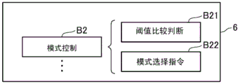
Specifically, the control unit 6 obtains a mode selection function B2 as schematically shown in fig. 11 by executing a control program of the CPU 6B. Therefore, a comparison determination between the detection value detected by the rotation speed detector 12 and the lower limit rotation speed, one 2 nd threshold value C1, the other 2 nd threshold value C2, and the limit rotation speed is performed by this mode selection function B2 (threshold comparison determination B21). Then, the control unit 6 selectively instructs the driving modes of the inverters 5a and 5B from the combination of the 3-phase/2-phase mode and the large/medium/small mode for each range of the rotation speed by the mode selection function B2 based on the threshold comparison determination (mode selection command B22).
The mode selection instruction B22 is adopted
Selecting a drive mode from a total of 3 modes of a large mode, a medium mode, and a small mode of the 3-phase mode in a case where the detected rotation speed is less than the lower limit rotation speed,
when it is determined that the detected rotation speed is within the range of not less than the lower limit rotation speed and less than one 2 nd threshold value C1, the drive mode is selected from 6 modes in total, i.e., a large mode, a medium mode, and a small mode, of each of the 3-phase mode and the 2-phase mode,
when it is determined that the detected rotation speed is within a range of one 2 nd threshold value C1 or more and less than another 2 nd threshold value C2, the drive mode is selected from 4 modes in total of the middle mode and the small mode of each of the 3-phase mode and the 2-phase mode,
when it is determined that the detected rotation speed is within the range of the other 2 nd threshold value C2 or more and less than the limit rotation speed, the drive mode is selected from 2 modes in total, which are small modes of the 3-phase mode and the 2-phase mode.
Typically, in the above-described drive mode, that is, when the detection value detected by the rotation speed detector 12 is smaller than one 2 nd threshold value C1, the rotating electrical machine 4 is operated as a motor by adopting any mode from the large mode, the medium mode, and the small mode of the 3-phase mode and the 2-phase mode. Thereby, the internal combustion engine 3 can be assisted by the output of any selected torque.
When the detection value detected by the rotation speed detector 12 is greater than one 2 nd threshold value C1 and less than the other 2 nd threshold value C2, the controller 6 operates the rotating electrical machine 4 as a motor in the middle mode or the small mode of each of the 3-phase mode and the 2-phase mode. Thereby, the internal combustion engine 3 can be assisted by any output of the medium speed medium torque or the medium speed small torque.
When the detection value detected by the rotation speed detector 12 is larger than the other 2 nd threshold value C2, the control unit 6 operates the rotating electrical machine 4 as a motor in a small mode of the 3-phase mode or the 2-phase mode. Thereby, the internal combustion engine 3 can be assisted by any output of the high speed-to-torque high speed-to-low torque.
[ effect of embodiment 2 ]
In this manner, in the system 1 according to embodiment 2, the rotary electric machine 4 can change the actual number of turns for each phase by providing the center tap 14 for each of the phase windings 7U to 7W.
The control unit 6 controls the operation of the rotating electric machine 4 by sequentially selecting the switches S that are turned on and off from among the switches S included in the two inverters 5a and 5b, and by sequentially changing the inverter operation of the switch S to be selected. Also, the control section 6 changes the actual number of turns for each phase by performing the inverter operation. Here, fig. 11 shows a function provided by the CPU6B reading the control program of embodiment 2 of the memory 6C and executing the program, that is, a functional block of the control unit 6.
This makes it possible to increase or decrease the actual number of turns for each phase at high speed, and therefore, to change the output of the electric motor or the electric generator at high speed, or to switch the operation of the rotating electrical machine 4 between the electric motor and the electric generator at high speed. Therefore, the system 1 can improve the fuel consumption reduction effect.
The controller 6 has 2 nd threshold values C1 and C2 corresponding to the rotation speed of the internal combustion engine 3, and changes the actual number of turns for each phase based on the result of comparison between the detection value detected by the rotation speed detector 12 and the 2 nd threshold values C1 and C2. This makes it possible to change the output of the rotating electrical machine 4 at a high speed in response to the load variation of the internal combustion engine 3.
The control unit 6 determines whether or not to operate the rotating electrical machine 4 as a motor based on the charge balance of the battery 2 predicted using the age of the detection value detected by the voltage detector 15 or the detection value detected by the voltage detector 15 at the time of starting the internal combustion engine 3.
This can reduce the influence of voltage fluctuations of the battery 2 on other electrical loads, which is caused by operating the rotating electrical machine 4 as a motor.
[ embodiment 3 ]
The system 1 of embodiment 3 is explained. In embodiment 3, a description will be given mainly of a configuration different from that of system 1 of embodiment 2, and the same reference numerals are used for the same configurations as those described in embodiment 2, and the description thereof will be omitted or simplified.
In the control section 6 of the system 1 of embodiment 3, as shown in fig. 12, the functions of the control section 6 are provided by the CPU6B reading the control program of embodiment 3 of the storage 6C and executing the program. This function also includes a stroke determination unit 17 (fig. 12: functions as a process determination means) that determines the stroke of the internal combustion engine 3. The stroke determining unit 17, that is, the control unit 6 determines the stroke of the internal combustion engine 3, for example, by using a signal (a signal indicating a crank angle) output from the rotation speed detector 12, a signal indicating the intake pressure of the internal combustion engine 3, and the like.
The control unit 6 determines whether or not to operate the rotating electrical machine 4 as a motor based on the determination result determined by the stroke determination unit 17 (see block B31 of fig. 12).
When the stroke determination unit 17 determines that the stroke of the internal combustion engine 3 is at least the compression stroke or the explosion stroke, the control unit 6 operates the rotating electrical machine 4 as a motor (see block diagram 32 of fig. 12). For example, as shown in fig. 9, the rotary electric machine 4 is operated as a motor in the second half of the compression stroke, the entire explosion stroke, and the first half of the exhaust stroke, which are considered to be particularly effective for assisting the internal combustion engine 3.
Further, the control unit 6 operates the rotating electrical machine 4 as a generator at a time other than the period in which the rotating electrical machine 4 is operated as a motor (see block B33 of fig. 12). Further, the control unit 6 extends or shortens the period during which the rotating electrical machine 4 is operated as a motor in accordance with the charge balance of the battery 2. That is, when it is considered that the amount of charge of the battery 2 is decreased, the control unit 6 shortens the period during which the rotating electrical machine 4 is operated as a motor.
In the above, the system 1 of embodiment 3 is adopted in accordance with the stroke of the internal combustion engine 3. The operation of the rotating electrical machine 4 is switched between the motor and the generator more finely. The fuel consumption reduction effect can be further improved.
In addition, according to the system 1 of embodiment 3, while the rotating electrical machine 4 is operated as a motor, it is possible to further expect that the 2-phase mode is performed in the explosion stroke and the exhaust stroke by the interlocking of the internal combustion engine 3, and the 3-phase mode is performed in the other times.
This can promote cost reduction and size reduction of the system 1 using the 2-phase mode.
[ modified example ]
The invention of the present application is not limited to the embodiments, and various modifications can be considered.
For example, although the system 1 according to the embodiment is provided with 1 intermediate tap 8U, 8V, 8W for each phase, for example, two or more intermediate taps 8U to 8W may be provided, and the number of the inverters 5 may be increased according to the increase in the number of the intermediate taps 8U to 8W.
In addition, in the system 1 according to embodiment 2 and embodiment 3, the intermediate taps 8U to 8W are provided to the windings 7U to 7W of the rotating electric machine 4, and the plurality of inverters 5 are connected to the windings 7U to 7W, so that the actual number of turns can be changed by the control unit 6, and for example, the actual number of turns per phase may be increased or decreased by turning on or off the relay switch in the windings 7U to 7W of each phase so that the actual number of turns per phase is variable.
In addition, although the windings 7U to 7W of the embodiment are used, for example, the windings 7U1 and 7U2 are connected in series in the winding 7U, and the actual number of turns of the windings 7U1 and 7U2 is set to n, which is the same, the form of the windings 7U to 7W is not limited to this. For example, the winding 7U1 is provided by connecting two windings of the actual number n of turns in parallel.
The motor generator in which the number of poles of the rotor and the number of poles of the stator of the rotating electric machine 4 are 3 phases is not limited to the general 12 poles and 18 poles, and delta (Δ) connection may be used as a connection method of the windings.
The timing for switching the operation of the rotating electrical machine 4 between the motor and the generator is not limited to the example, and may be switched at regular intervals or may be switched according to temperature conditions or the like.
In addition, the control unit 6 may execute the short-circuit mode described below in order to increase the engine brake during deceleration or the like. That is, the short-circuit mode is a control mode for short-circuiting the induced voltages of the windings 7U to 7W to the ground by the inverter operation, and is different from a control mode for operating the rotating electrical machine 4 as a motor or a generator.
Here, with the system 1 of embodiment 2 and embodiment 3, for example, the switches Sun1, Svn1, and Swn1 may be turned on in the short-circuit mode to short-circuit the generated current, or the switches Sun2, Svn2, and Swn2 may be turned on in addition to the switches Sun1, Svn1, and Swn 1.
At this time, for example, when the generated currents generated by the windings 7U1, 7U2, 7V1, and 7V2 are short-circuited, the switches Sun1 and Svn1 are opened to enable short-circuiting, but the switches Sun2 and Svn2 are opened in addition to the switches Sun1 and Svn1, so that heat generated at the time of short-circuiting can be dissipated, and the braking capability can be improved.
Further, the power generation, the driving assistance, and the engine braking may be optimized by adjusting the degree thereof by PWM control or the like as appropriate. In addition, the short-circuit mode may be performed at regular intervals regardless of the stroke of the internal combustion engine 3.
Further, in the system 1 of the embodiment, as the 2-phase mode, the mode in which the 1 st pattern to the 3 rd pattern are not executed is exemplified, but, for example, only 1 of the 1 st pattern to the 3 rd pattern in which the 3-phase mode is not executed may be adopted. For example, in the system 1 of embodiment 1, when the 2 nd and 3 rd patterns are executed without executing the 1 st pattern (the combination in which the windings 7W and 7U are on the high potential side), the 4 th pattern may be adopted instead of the 1 st pattern, and the 2 nd phase mode may be partially realized by repeating three patterns of the 4 th pattern, the 2 nd pattern, and the 3 rd pattern.
The present disclosure is described based on the embodiments, but the present disclosure is not to be construed as being limited to the embodiments and the structures. The present disclosure also includes various modifications and equivalent variations. Various combinations and forms, and other combinations and forms including only one of the elements, more than the above, or less than the above are also within the scope and spirit of the present disclosure.
Claims (9)
1. A motor device (1) for a vehicle includes: a rotating electrical machine (4) having 3-phase windings (7U-7W); a switch (S) that turns on and off the application of voltage to the windings (7U-7W); and a control means (6) for giving a command to the switch (S) to control the operation of the rotating electric machine (4),
based on the control of the control means (6), the rotating electrical machine (4) is operated as a motor by supplying power from the battery (2), and the output of the internal combustion engine (3) is assisted by the output generated as the operation of the motor,
the motor device (1) comprises a rotational speed detection means (12) for detecting the rotational speed of the internal combustion engine (3),
the control unit (6) has:
a 3-phase mode in which the 1 st combinations (7W, 7U), the 2 nd combinations (7U, 7V), and the 3 rd combinations (7V, 7W) are sequentially repeated as combinations of the windings (7U to 7W) that become the high potential side when the voltage of the battery (2) is applied to the windings (7U to 7W) of the 3 phases; and
a 2-phase mode not performing at least 1 combination of the 1 st combination (7W, 7U), the 2 nd combination (7U, 7V), and the 3 rd combination (7V, 7W),
the motor device (1) for a vehicle is characterized in that,
the control means (6) has a 1 st threshold value (C0) corresponding to the rotation speed of the internal combustion engine (3), the control means (6) uses the 2-phase mode when the detection value detected by the rotation speed detection means (12) is larger than the 1 st threshold value (C0),
the motor device (1) further comprises a stroke determination means (17) for determining the stroke of the internal combustion engine (3),
the control means (6) determines whether or not to operate the rotating electrical machine (4) as the motor, based on the determination result determined by the stroke determination means (17).
2. The motor apparatus (1) according to claim 1,
the control means (6) has 3 or more options as the 2-phase mode, and sequentially switches at least two options among the 3 or more options when the 2-phase mode is used.
3. The motor apparatus (1) according to claim 1 or claim 2,
the control unit (6) uses the 3-phase mode when the detection value detected by the rotation speed detection unit (12) is smaller than the 1 st threshold (C0).
4. The motor apparatus (1) according to claim 1 or 2,
the rotating electrical machine (4) has the number of turns, i.e., the actual number of turns, of the portion of the windings (7U-7W) that is energized by the power supplied from the battery (2) variable for each phase,
the control means (6) further changes the actual number of turns for each phase change.
5. The motor apparatus (1) according to claim 4,
the control means (6) has a 2 nd threshold value corresponding to the rotation speed of the internal combustion engine (3), and the actual number of turns is changed for each phase according to the result of comparison between the detection value detected by the rotation speed detection means (12) and the 2 nd threshold value.
6. The motor apparatus (1) according to claim 1,
the period in which the rotary electric machine (4) is operated as the motor includes a period in which the stroke determination means (17) determines that the compression stroke is performed.
7. The motor apparatus (1) according to claim 1 or 2,
the motor device (1) has a voltage detection means (15) for detecting the voltage of the battery (2),
the control means (6) determines whether or not to operate the rotating electrical machine (4) as the electric motor, based on a charge balance of the battery (2) predicted using a change over time of a detection value detected by the voltage detection means (15), or a detection value detected by the voltage detection means (15) at the time of starting the internal combustion engine (3).
8. The motor apparatus (1) according to claim 1 or 2,
the rotor of the rotating electrical machine (4) is directly connected to the crankshaft of the internal combustion engine (3).
9. The motor apparatus (1) according to claim 1 or 2,
the motor device (1) has an inverter (5) connected to the 3-phase windings (7U-7W),
the rotating electrical machine (4) controls the operation of the rotating electrical machine (4) by operating the turning on and off of a semiconductor switch (S) provided in the inverter (5),
the control means (6) controls charging of the battery (2) by a parasitic diode attached to the semiconductor switch (S) that is not turned on by operation of the inverter (5).
Applications Claiming Priority (3)
| Application Number | Priority Date | Filing Date | Title |
|---|---|---|---|
| JP2015-078198 | 2015-04-07 | ||
| JP2015078198A JP6492901B2 (en) | 2015-04-07 | 2015-04-07 | Electric motor device |
| PCT/JP2016/061401 WO2016163459A1 (en) | 2015-04-07 | 2016-04-07 | Electrical motor device |
Publications (2)
| Publication Number | Publication Date |
|---|---|
| CN107531232A CN107531232A (en) | 2018-01-02 |
| CN107531232B true CN107531232B (en) | 2020-01-07 |
Family
ID=57073241
Family Applications (1)
| Application Number | Title | Priority Date | Filing Date |
|---|---|---|---|
| CN201680020380.2A Active CN107531232B (en) | 2015-04-07 | 2016-04-07 | Motor device |
Country Status (3)
| Country | Link |
|---|---|
| JP (1) | JP6492901B2 (en) |
| CN (1) | CN107531232B (en) |
| WO (1) | WO2016163459A1 (en) |
Families Citing this family (1)
| Publication number | Priority date | Publication date | Assignee | Title |
|---|---|---|---|---|
| US11414065B2 (en) * | 2018-12-17 | 2022-08-16 | Quantentech Limited | Hybrid electric vehicle system and control method |
Citations (11)
| Publication number | Priority date | Publication date | Assignee | Title |
|---|---|---|---|---|
| CA2252842C (en) * | 1997-02-20 | 2001-05-22 | Honda Giken Kogyo Kabushiki Kaisha | Generator motor for internal combustion engine |
| JP2001271759A (en) * | 2000-03-24 | 2001-10-05 | Tokico Ltd | Air compressor and its control method |
| JP2005057818A (en) * | 2003-08-01 | 2005-03-03 | Aisin Aw Co Ltd | Motor drive controller, motor drive controlling method, and its program |
| CN1860675A (en) * | 2003-10-02 | 2006-11-08 | 东芝开利株式会社 | Motor operation control device |
| JP2007288858A (en) * | 2006-04-13 | 2007-11-01 | Sharp Corp | Motor controller, refrigerator, and air conditioner |
| JP2008019789A (en) * | 2006-07-13 | 2008-01-31 | Honda Motor Co Ltd | Control system for electric motor |
| CN101535611A (en) * | 2006-11-15 | 2009-09-16 | 三菱电机株式会社 | Hybrid engine assist system for vehicle |
| CN101682288A (en) * | 2007-11-01 | 2010-03-24 | 爱信艾达株式会社 | Motor controller, electric vehicle and hybrid electric vehicle |
| JP2012130220A (en) * | 2010-12-17 | 2012-07-05 | Aisin Aw Co Ltd | Rotary electric machine controlling apparatus |
| JP2014058825A (en) * | 2012-09-18 | 2014-04-03 | Hitachi Constr Mach Co Ltd | Construction machine |
| RU2013133516A (en) * | 2013-07-18 | 2015-01-27 | Российская Федерация, От Имени Которой Выступает Министерство Промышленности И Торговли Российской Федерации | METHOD OF CONTROL MOTOR-GENERATOR |
-
2015
- 2015-04-07 JP JP2015078198A patent/JP6492901B2/en active Active
-
2016
- 2016-04-07 CN CN201680020380.2A patent/CN107531232B/en active Active
- 2016-04-07 WO PCT/JP2016/061401 patent/WO2016163459A1/en active Application Filing
Patent Citations (11)
| Publication number | Priority date | Publication date | Assignee | Title |
|---|---|---|---|---|
| CA2252842C (en) * | 1997-02-20 | 2001-05-22 | Honda Giken Kogyo Kabushiki Kaisha | Generator motor for internal combustion engine |
| JP2001271759A (en) * | 2000-03-24 | 2001-10-05 | Tokico Ltd | Air compressor and its control method |
| JP2005057818A (en) * | 2003-08-01 | 2005-03-03 | Aisin Aw Co Ltd | Motor drive controller, motor drive controlling method, and its program |
| CN1860675A (en) * | 2003-10-02 | 2006-11-08 | 东芝开利株式会社 | Motor operation control device |
| JP2007288858A (en) * | 2006-04-13 | 2007-11-01 | Sharp Corp | Motor controller, refrigerator, and air conditioner |
| JP2008019789A (en) * | 2006-07-13 | 2008-01-31 | Honda Motor Co Ltd | Control system for electric motor |
| CN101535611A (en) * | 2006-11-15 | 2009-09-16 | 三菱电机株式会社 | Hybrid engine assist system for vehicle |
| CN101682288A (en) * | 2007-11-01 | 2010-03-24 | 爱信艾达株式会社 | Motor controller, electric vehicle and hybrid electric vehicle |
| JP2012130220A (en) * | 2010-12-17 | 2012-07-05 | Aisin Aw Co Ltd | Rotary electric machine controlling apparatus |
| JP2014058825A (en) * | 2012-09-18 | 2014-04-03 | Hitachi Constr Mach Co Ltd | Construction machine |
| RU2013133516A (en) * | 2013-07-18 | 2015-01-27 | Российская Федерация, От Имени Которой Выступает Министерство Промышленности И Торговли Российской Федерации | METHOD OF CONTROL MOTOR-GENERATOR |
Also Published As
| Publication number | Publication date |
|---|---|
| WO2016163459A1 (en) | 2016-10-13 |
| CN107531232A (en) | 2018-01-02 |
| JP6492901B2 (en) | 2019-04-03 |
| JP2016201861A (en) | 2016-12-01 |
Similar Documents
| Publication | Publication Date | Title |
|---|---|---|
| US9979329B2 (en) | Power converting device and power converting system | |
| JP4483911B2 (en) | Rotating electric machine for vehicles | |
| RU2660963C1 (en) | Scheme and method of controlling a reactive electrically commutated motor | |
| JP4655431B2 (en) | Generator motor device for vehicle | |
| JP5174617B2 (en) | Rotating electrical machine device and control device thereof | |
| JP7243676B2 (en) | Power converter control circuit | |
| CN107531232B (en) | Motor device | |
| JP7259563B2 (en) | Rotating electric machine control system | |
| JP5441979B2 (en) | Power converter control device and control method | |
| JP2004320861A (en) | Controller for three-phase motor-generator for vehicle | |
| WO2016163458A1 (en) | Electromotive power-generator device | |
| US20220321035A1 (en) | Motor control apparatus | |
| CN111279607A (en) | Control device for rotating electric machine | |
| JP5225709B2 (en) | Switched reluctance motor controller | |
| JP6541844B1 (en) | Control device of rotating electric machine | |
| JP2004129379A (en) | Motor control device and computer-readable recording medium stored with program for making computer execute driving control of motor | |
| JP5441951B2 (en) | Rotating electric machine | |
| JP4983939B2 (en) | Synchronous motor drive device | |
| JP6377190B2 (en) | Control device and control method for rotating electrical machine | |
| JP6645405B2 (en) | Rotary electric machine control device, rotary electric machine unit | |
| US12101046B2 (en) | Motor driving apparatus | |
| JP2016201861A5 (en) | ||
| EP4239876A1 (en) | Motor driving apparatus | |
| JP7206722B2 (en) | motor generator controller | |
| JP6058085B1 (en) | Rotating electric machine and control method of rotating electric machine |
Legal Events
| Date | Code | Title | Description |
|---|---|---|---|
| PB01 | Publication | ||
| PB01 | Publication | ||
| SE01 | Entry into force of request for substantive examination | ||
| SE01 | Entry into force of request for substantive examination | ||
| GR01 | Patent grant | ||
| GR01 | Patent grant |