CN107252742B - Degassing and oil-removing hydraulic coalescence device - Google Patents
Degassing and oil-removing hydraulic coalescence device Download PDFInfo
- Publication number
- CN107252742B CN107252742B CN201710491548.4A CN201710491548A CN107252742B CN 107252742 B CN107252742 B CN 107252742B CN 201710491548 A CN201710491548 A CN 201710491548A CN 107252742 B CN107252742 B CN 107252742B
- Authority
- CN
- China
- Prior art keywords
- channel
- coalescence
- separation
- oil
- pressurizing
- Prior art date
- Legal status (The legal status is an assumption and is not a legal conclusion. Google has not performed a legal analysis and makes no representation as to the accuracy of the status listed.)
- Active
Links
Images


Classifications
-
- B—PERFORMING OPERATIONS; TRANSPORTING
- B04—CENTRIFUGAL APPARATUS OR MACHINES FOR CARRYING-OUT PHYSICAL OR CHEMICAL PROCESSES
- B04C—APPARATUS USING FREE VORTEX FLOW, e.g. CYCLONES
- B04C5/00—Apparatus in which the axial direction of the vortex is reversed
-
- B—PERFORMING OPERATIONS; TRANSPORTING
- B04—CENTRIFUGAL APPARATUS OR MACHINES FOR CARRYING-OUT PHYSICAL OR CHEMICAL PROCESSES
- B04C—APPARATUS USING FREE VORTEX FLOW, e.g. CYCLONES
- B04C5/00—Apparatus in which the axial direction of the vortex is reversed
- B04C5/02—Construction of inlets by which the vortex flow is generated, e.g. tangential admission, the fluid flow being forced to follow a downward path by spirally wound bulkheads, or with slightly downwardly-directed tangential admission
- B04C5/06—Axial inlets
-
- B—PERFORMING OPERATIONS; TRANSPORTING
- B04—CENTRIFUGAL APPARATUS OR MACHINES FOR CARRYING-OUT PHYSICAL OR CHEMICAL PROCESSES
- B04C—APPARATUS USING FREE VORTEX FLOW, e.g. CYCLONES
- B04C5/00—Apparatus in which the axial direction of the vortex is reversed
- B04C5/08—Vortex chamber constructions
- B04C5/107—Cores; Devices for inducing an air-core in hydrocyclones
-
- B—PERFORMING OPERATIONS; TRANSPORTING
- B04—CENTRIFUGAL APPARATUS OR MACHINES FOR CARRYING-OUT PHYSICAL OR CHEMICAL PROCESSES
- B04C—APPARATUS USING FREE VORTEX FLOW, e.g. CYCLONES
- B04C5/00—Apparatus in which the axial direction of the vortex is reversed
- B04C5/12—Construction of the overflow ducting, e.g. diffusing or spiral exits
- B04C5/13—Construction of the overflow ducting, e.g. diffusing or spiral exits formed as a vortex finder and extending into the vortex chamber; Discharge from vortex finder otherwise than at the top of the cyclone; Devices for controlling the overflow
-
- B—PERFORMING OPERATIONS; TRANSPORTING
- B04—CENTRIFUGAL APPARATUS OR MACHINES FOR CARRYING-OUT PHYSICAL OR CHEMICAL PROCESSES
- B04C—APPARATUS USING FREE VORTEX FLOW, e.g. CYCLONES
- B04C5/00—Apparatus in which the axial direction of the vortex is reversed
- B04C5/14—Construction of the underflow ducting; Apex constructions; Discharge arrangements ; discharge through sidewall provided with a few slits or perforations
- B04C5/181—Bulkheads or central bodies in the discharge opening
-
- Y—GENERAL TAGGING OF NEW TECHNOLOGICAL DEVELOPMENTS; GENERAL TAGGING OF CROSS-SECTIONAL TECHNOLOGIES SPANNING OVER SEVERAL SECTIONS OF THE IPC; TECHNICAL SUBJECTS COVERED BY FORMER USPC CROSS-REFERENCE ART COLLECTIONS [XRACs] AND DIGESTS
- Y02—TECHNOLOGIES OR APPLICATIONS FOR MITIGATION OR ADAPTATION AGAINST CLIMATE CHANGE
- Y02A—TECHNOLOGIES FOR ADAPTATION TO CLIMATE CHANGE
- Y02A20/00—Water conservation; Efficient water supply; Efficient water use
- Y02A20/20—Controlling water pollution; Waste water treatment
- Y02A20/204—Keeping clear the surface of open water from oil spills
Landscapes
- Physics & Mathematics (AREA)
- Fluid Mechanics (AREA)
- Cyclones (AREA)
Abstract
A degassing and oil-removing hydraulic coalescence device. The main purpose is to provide a novel separation device for separating gas-liquid three-phase media. The method is characterized in that: a first-stage variable-pitch supercharging body (6) and a coalescence separation pipe (7) are arranged in the coalescence outer cylinder (2); the first-stage variable-pitch pressurizing body (6) is connected with the coalescence-separation pipe (7) through threads; the tail end of the coalescence-separation pipe (7) penetrates through the diversion outer cylinder (3) and then is connected with a secondary variable-flow-channel pressurizing body (9) positioned in the variable-diameter separation cylinder (4); the secondary variable-flow-channel pressurizing body is formed by integrally connecting a secondary flow guide channel (23) and a secondary pressurizing channel (24). The device realizes the coalescence of the oil phase after the degassing between a gas phase and a two-phase liquid medium with different densities and then carries out the liquid-liquid separation, thereby removing the adverse effect of the gas phase on the liquid-liquid separation, increasing the particle size of the oil phase and further improving the precision of the liquid-liquid separation.
Description
The technical field is as follows:
the invention relates to a separation device for separating a gas-liquid three-phase medium.
Background art:
in the research and development process of the multi-phase medium separation technology, in order to adapt to the application of different requirements and different occasions, various separation methods and forms such as cyclone separation, coalescence separation, sedimentation separation, chemical separation and the like are formed. The cyclone separation has the advantages of small equipment volume, high separation speed and the like and is widely applied to the field of multiphase flow separation. Conventional hydrocyclone designs typically consist of a tangential inlet, a large cone section, a small cone section, an underflow opening and an overflow opening. The mixed liquid enters the rotational flow cavity from the tangential inlet, the fluid medium is further accelerated through the two conical sections, the rotational flow liquid is separated according to different densities, the light phase flows out from the overflow port, and the heavy phase is discharged from the underflow port. This type of cyclone is generally only suitable for pre-separation of two-phase media and is not suitable for high-precision separation of three-phase media. Coalescence can be divided into hydraulic coalescence, i.e. increasing the probability of collision between droplets to change small droplets into large droplets, and material coalescence, according to the separation method, to accelerate the separation efficiency and accuracy. Meanwhile, the coalescence-separation of materials has the advantage of high-precision separation, but the separation speed is low, a long coalescence time is generally needed, the coalescence is usually used together with a sedimentation separation method to realize the separation between media, but the separation speed is low, and the rapid continuous separation between the media cannot be guaranteed.
The invention content is as follows:
in order to solve the technical problems mentioned in the background technology, the invention provides a novel three-phase separation device for firstly degassing and then carrying out liquid-liquid separation, which makes a new breakthrough on the basis of the traditional three-phase medium separation method, is mainly used for realizing the coalescence of an oil phase after degassing between a gas phase and two-phase liquid media with different densities and then carrying out liquid-liquid separation so as to remove the adverse effect of the gas phase on the liquid-liquid separation and increase the particle size of the oil phase so as to improve the liquid-liquid separation precision.
The technical scheme of the invention is as follows: the degassing and oil removing hydraulic coalescence device comprises a coalescence outer cylinder, a flow guide outer cylinder, a reducing separation cylinder and an underflow pipe which are sequentially connected, and is characterized in that:
a first-stage variable-pitch pressurizing body and a coalescence separation pipe are arranged in the coalescence outer cylinder;
the primary variable-pitch supercharging body is formed by integrally connecting a first straight pipe section, a drainage cone, a primary flow guide channel and a primary supercharging runner in sequence; the spiral directions of the flow channels on the first-stage flow guide channel and the first-stage pressurizing flow channel are the same, but the spiral rising angles of the first-stage flow guide channel and the first-stage pressurizing flow channel are different, and the rising angle of the first-stage flow guide channel is changed from large to small, so that the butt joint of the incoming liquid after flow guide and the first-stage pressurizing flow channel is ensured; the screw pitches of the first-stage flow guide channel and the first-stage pressurizing flow channel are also different, the screw pitch of the first-stage flow guide channel is changed from big to small, and the screw pitch of the first-stage pressurizing flow channel is constant; at the spiral connection position of the primary flow guide channel and the primary pressurizing flow channel, smooth curve transition is adopted, so that the stability of the flowing of the incoming liquid is ensured, and the emulsification is reduced; the inner cavities of the first straight pipe section, the drainage cone, the first-stage flow guide channel and the first-stage pressurizing flow channel are hollow, an oil delivery conduit fixed through an annular support frame is arranged in the hollow inner cavities, and an annular space is reserved between the oil delivery conduit and the hollow inner cavity walls of the first straight pipe section, the drainage cone, the first-stage flow guide channel and the first-stage pressurizing flow channel; an annular space formed between the head end of the first straight pipe section and the oil conveying guide pipe is a gas phase outlet, and a port on the oil conveying guide pipe, which is close to the gas phase outlet, is an oil phase outlet; the tail end of the cavity of the primary pressurizing flow passage is provided with a positioning threaded hole for connecting with an oil conveying guide pipe, and the pipe wall of the tail end of the primary pressurizing flow passage is provided with a positioning groove for connecting with a coalescence separation pipe;
the head end and the tail end of the coalescence-separation pipe are both straight pipes, a separation pipe positioning thread is arranged at the straight pipe at the head end, and the separation pipe positioning thread is matched with the positioning threaded hole; the main body of the coalescence-separation pipe is a conical pipe, and the upper end of the conical pipe is provided with a plurality of degassing holes; the oil conveying conduit is positioned in the center of the coalescence-separation pipe, the tail end of the oil conveying conduit is an oil phase inlet, and an annular space formed between the oil phase inlet and the tail end of the coalescence-separation pipe is an oil gathering port;
the first-stage variable-pitch pressurizing body is connected with the coalescence-separation pipe through threads; the tail end of the coalescence-separation pipe extends out of the tail end of the coalescence-separation outer cylinder, and an annular space formed between the tail end of the coalescence-separation pipe and the outer wall of the coalescence-separation pipe is an annular coalescence channel;
the tail end of the coalescence-separation pipe penetrates through the guide outer cylinder and then is connected with a secondary variable-flow-channel pressurizing body in the variable-diameter separation cylinder; the secondary variable flow passage supercharging body is formed by integrally connecting a secondary flow guide channel and a secondary supercharging channel; the spiral directions of the flow channels on the secondary flow guide channel and the secondary pressurizing channel are the same, but the spiral rising angles of the secondary flow guide channel and the secondary pressurizing channel are different, and the rising angle of the secondary flow guide channel is changed from large to small, so that the butt joint between the flow guide channel and the secondary pressurizing channel after the incoming liquid is guided is ensured; the screw pitches of the secondary flow guide channel and the secondary pressurizing flow channel are different, and the former is larger than the latter; adopting smooth curve transition at the spiral connection part of the secondary flow guide channel and the secondary pressurizing flow channel;
a lower liquid flow channel is formed in the center of the secondary pressurizing flow channel, and the bottom end of the lower liquid flow channel is an overflow port; an upper liquid flow channel is arranged in the center of the secondary flow guide channel; the upper fluid flow channel is communicated with the lower fluid flow channel; the top end of the upper liquid flow channel is provided with a secondary positioning threaded hole which is used for connecting an oil delivery conduit from the tail end part of the coalescence-separation pipe; in the secondary flow guide channel, a circle of annular oil gathering channel is arranged around the upper liquid flow channel, and the bottom of the oil gathering channel is a blind groove and is not communicated with the secondary pressurizing flow channel; an annular secondary positioning groove is formed around the top end of the oil gathering channel and used for connecting the tail end of the coalescence-separation pipe;
and a plurality of oil distribution holes are formed in the pipe wall of the secondary flow guide channel at the interval of the two spiral lines, and the oil distribution holes penetrate into the oil gathering channel from the pipe wall along the radial direction.
The invention has the following beneficial effects:
now, the beneficial effects of the invention are illustrated by taking an oil-gas-water three-phase mixed medium as an example: the mixed liquid enters the device from the axial inlet, and generates tangential acceleration under the action of the first-stage variable pitch pressurizing body, so that the mixed liquid does rotary motion around the axis in the annular coalescence channel at the front end of the device. Heavy water phase moves towards the side wall of the device under the action of centrifugal force, light gas phase moves towards the axis, oil phase is between gas phase and water phase, gas phase enters an annular area between the coalescence-separation pipe and the oil conveying pipe along the degassing hole and then is discharged out of the device through a gas phase outlet at the top end, and at the moment, fine oil drop particles collide at the axis and coalesce into large oil drops which enter the separation chamber along the axis. After the oil phase is coalesced, the particle size of the oil phase is changed from small to large, and when the oil-water enters the secondary separation chamber, the oil phase is close to the axis, so that the oil-water mixed liquid can be separated more easily in the secondary separation chamber, and the high-precision separation of the oil-water is ensured. The separated oil phase moves upwards along the axial direction of the overflow hole until the oil phase is discharged from the light phase outlet, and the water phase moves downwards in the separation chamber and is discharged from the underflow pipe, so that the three-phase medium separation is realized. Meanwhile, after entering an annular area along with a gas phase, part of oil phase in the mixed liquid sinks into the bottom of the device under the action of gravity and enters the annular area inside the secondary variable-pitch pressurizing body from the oil collecting port, the oil phase is collected with the oil phase after coalescence by the oil separating port on the flow passage, and the oil phase is discharged out of the device through an overflow port together.
The invention organically combines the hydraulic coalescence technology and the cyclone separation technology together, so that discrete phase oil drops are coalesced under the effect of supergravity, small oil drops are changed into large oil drops before the oil phase is subjected to cyclone separation, and the oil phase is ensured to be positioned close to an overflow port in the radial direction, thereby improving the oil-water separation efficiency and precision. Makes up the respective defects of cyclone separation and coalescence separation, and realizes continuous high-precision separation of the mixed medium under the condition of no external force pressurization. Meanwhile, the device realizes gas-liquid separation before oil-water separation, eliminates the adverse effect of gas-containing conditions on oil-water separation, and ensures the efficient operation of degassing and deoiling. The degassing, oil removing and hydraulic coalescing device has reasonable structural design, better separation performance and higher separation precision, and can be suitable for the separation of three-phase media in various states.
In addition, the invention also has the advantages of simple treatment process, continuous operation, flexible and convenient use, small equipment volume, convenient installation, low operation cost, energy conservation, consumption reduction and the like, and can be used for separating three-phase media in different forms. The advantages of the invention can be widely applied in the fields of petrochemical industry, metallurgy, water treatment and the like.
Description of the drawings:
FIG. 1 is an external view of a degassing, degreasing and hydraulic coalescing apparatus according to the present invention.
FIG. 2 is an overall cross-sectional view of a degassing, degreasing, hydraulic coalescing apparatus according to the present invention.
FIG. 3 is a three-dimensional cross-sectional view of a degassing, degreasing, hydraulic coalescing apparatus according to the present invention.
Fig. 4 is an overall cross-sectional view of a hydraulic degassing coalescing section at the upper end of a degassing, degreasing, hydraulic coalescing apparatus according to the present invention.
Fig. 5 is a three-dimensional cross-sectional view of a hydraulic degassing coalescing section at an upper end of a degassing, degreasing, hydraulic coalescing apparatus according to the present invention.
FIG. 6 is a schematic structural diagram of a primary variable pitch plenum in the degassing, degreasing and hydraulic coalescing device of the present invention.
FIG. 7 is a sectional view of the configuration of a first stage variable pitch plenum in a degassing, oil removal hydraulic coalescing assembly according to the present invention.
Fig. 8 is a schematic structural diagram of a coalescence-separation pipe in the degassing, oil-removing and hydraulic coalescence device according to the present invention.
FIG. 9 is a sectional view showing the structure of the coalescence-separation pipe connected to the first-stage variable-pitch pressurizing body and the oil transfer pipe.
FIG. 10 is an external view of the coalescence-separation pipe connected to the first-stage variable-pitch booster body and the oil delivery pipe.
FIG. 11 is a schematic view showing the position of a bottom channel connecting a coalescence-separation pipe with a one-stage variable pitch pressurizing body.
FIG. 12 is a cross-sectional view of the oil delivery conduit after it is connected to the primary variable pitch plenum.
FIG. 13 is an overall external view of a hydraulic degassing coalescing section.
FIG. 14 is a schematic structural diagram of a two-stage variable pitch supercharging body.
FIG. 15 is a schematic bottom structure diagram of a two-stage variable pitch supercharging body.
FIG. 16 is a cross-sectional view of a two-stage variable pitch plenum.
FIG. 17 is a schematic view of the connection of the coalescence-separation tube to the liquid-liquid separation part of the apparatus.
FIG. 18 is a schematic diagram of the connection of the oil transfer conduit to the liquid-liquid separation section of the apparatus.
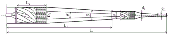
Fig. 19 is a drawing showing the main structural dimensions of the device.
In the figure, 1-a mixed liquid inlet and 2-a coalescence outer cylinder; 3-a diversion outer cylinder; 4-a reducing separation cylinder; 5-an underflow pipe; 6-first-stage variable-pitch pressurizing body; 7-a coalescing separation tube; 8-primary degassing holes; 9-a two-stage variable pitch supercharging body; 10-a water phase outlet; 11-a gas phase outlet; 12-oil phase outlet; 13-oil transportation conduit; 14-oil gathering port; 15-oil phase inlet; 16-an annular coalescence channel; 17-a drainage cone; 18-a primary flow guide channel; 19-a first-stage pressurizing flow channel; 20-positioning threaded holes and 21-positioning grooves; 22-separation tube positioning screw thread; 23-a secondary flow guide channel; 24-a secondary boost passage; 25-secondary positioning groove; 26-oil accumulation channel; 27-secondary positioning threaded holes; 28-overflow port; 29-oil separating hole.
The specific implementation mode is as follows:
in order to further realize high-efficiency multi-phase medium separation, under the subsidy of innovative scientific research projects (project number: YJSCX2017-019 NEPU) of researchers at northeast oil university, the design scheme provided by the invention is finally designed by repeatedly researching flow field characteristics, structural characteristics and separation principles in different separation methods and various separation devices. The invention mainly aims to provide the following steps: high-precision separation between gas-liquid three-phase media is realized in the integrated small device; the degassing treatment is carried out before the oil-water separation, so that the gas-liquid separation is realized, and the adverse effect of the gas-containing condition on the oil-water two-phase separation is eliminated; the hydraulic coalescence is realized before the oil phase is separated from the water phase, so that the separation precision is improved, and the defect of low separation efficiency of the conventional cyclone separation equipment is overcome; the collision probability of discrete phase small-particle-size liquid drops is increased before high-precision deoiling, so that the discrete phase particle size distribution entering a separation chamber is increased, and the performance and precision of cyclone separation are enhanced. The coalescence and separation of discrete phases in the same device are realized by skillfully combining the hydraulic coalescence and the cyclone separation.
The specific technical scheme is as follows:
the degassing, oil removing and hydraulic coalescing device comprises a coalescing outer cylinder 2, a diversion outer cylinder 3, a reducing separation cylinder 4 and an underflow pipe 5 which are sequentially connected, and is characterized in that:
a first-stage variable pitch supercharging body and a coalescence separation pipe 7 are arranged in the coalescence outer cylinder 2;
wherein, the primary variable-pitch pressurizing body 6 is formed by integrally connecting a first straight pipe section, a drainage cone 17, a primary flow guide channel 18 and a primary pressurizing flow channel 19 in sequence; the spiral directions of the flow channels on the first-stage flow guide channel 18 and the first-stage pressurizing flow channel 19 are the same, but the spiral rising angles of the first-stage flow guide channel 18 and the first-stage pressurizing flow channel 19 are different, and the rising angle of the first-stage flow guide channel is changed from large to small, so that the butt joint of the incoming liquid after flow guide and the first-stage pressurizing flow channel is ensured; the screw pitches of the first-stage flow guide channel 18 and the first-stage pressurizing flow channel 19 are also different, the screw pitch of the first-stage flow guide channel is changed from big to small, and the screw pitch of the first-stage pressurizing flow channel is constant; at the spiral connection part of the primary diversion channel 18 and the primary pressurizing channel 19, smooth curve transition is adopted, so that the stability of the flowing of the incoming liquid is ensured, and the emulsification is reduced; the inner cavities of the first straight pipe section, the drainage cone 17, the primary flow guide channel 18 and the primary pressurizing flow channel 19 are hollow, an oil delivery conduit 13 fixed through an annular support frame is arranged in the inner cavities, and an annular space is reserved between the oil delivery conduit 13 and the hollow inner cavity walls of the first straight pipe section, the drainage cone 17, the primary flow guide channel 18 and the primary pressurizing flow channel 19; an annular space formed between the head end of the first straight pipe section and the oil delivery conduit 13 is a gas phase outlet 11, and a port on the oil delivery conduit, which is close to the gas phase outlet 11, is an oil phase outlet 12; the tail end of the cavity of the primary pressurizing flow passage 12 is provided with a positioning threaded hole 20 for connecting with the oil delivery conduit 13, and the wall of the tail end of the primary pressurizing flow passage 19 is provided with a positioning groove 21 for connecting with the coalescence-separation pipe 7.
The head end and the tail end of the coalescence-separation pipe 7 are both straight pipes, a separation pipe positioning thread 22 is arranged at the straight pipe at the head end, and the separation pipe positioning thread 22 is matched with the positioning threaded hole 20; the main body of the coalescence-separation pipe 7 is a conical pipe, and the upper end of the conical pipe is provided with a plurality of degassing holes 8; the oil conveying pipe 13 is positioned in the center of the coalescence-separation pipe 7, the tail end of the oil conveying pipe 13 is an oil phase inlet 15, and an annular space formed between the oil phase inlet 15 and the tail end of the coalescence-separation pipe 7 is an oil gathering port 14.
The first-stage variable-pitch pressurizing body 6 is connected with the coalescence-separation pipe 7 through threads; the tail end of the coalescence-separation pipe 7 extends out of the tail end of the coalescence-separation pipe 2, and an annular space formed between the tail end of the coalescence-separation pipe 2 and the outer wall of the coalescence-separation pipe 7 is an annular coalescence channel 16.
The tail end of the coalescence-separation pipe 7 penetrates through the guide outer cylinder 3 and then is connected with a secondary variable-flow-channel pressurizing body 9 positioned in the variable-diameter separation cylinder 4; the secondary variable flow channel supercharging body is formed by integrally connecting a secondary flow guide channel 23 and a secondary supercharging channel 24; the spiral directions of the flow channels on the secondary flow guide channel 23 and the secondary pressurizing channel 24 are the same, but the spiral rising angles of the secondary flow guide channel 23 and the secondary pressurizing channel 24 are different, and the rising angles of the secondary flow guide channel are changed from large to small, so that butt joint between the incoming liquid after flow guide and the secondary pressurizing flow channels is guaranteed; the screw pitches of the secondary guide channel 23 and the secondary pressurizing channel 24 are also different, and the former is larger than the latter; and a smooth curve transition is adopted at the spiral connection part of the secondary guide channel 23 and the secondary pressurizing channel 24.
A lower liquid flow channel is arranged in the center of the secondary pressurizing channel 24, and the bottom end of the lower liquid flow channel is an overflow port 28; an upper liquid flow channel is arranged in the center of the secondary flow guide channel 23; the upper fluid flow channel is communicated with the lower fluid flow channel; the top end of the upper liquid flow channel is provided with a secondary positioning threaded hole 27 which is used for connecting an oil delivery conduit 13 from the tail end part of the coalescence-separation pipe 7; in the secondary diversion channel 23, a ring of annular oil gathering channel 26 is arranged around the upper liquid flow channel, and the bottom of the oil gathering channel is a blind groove and is not communicated with the secondary pressurizing channel 24; an annular secondary positioning groove 25 is formed around the top end of the oil gathering channel and is used for connecting the tail end of the coalescence-separation pipe 7.
On the tube wall of the secondary flow guide channel 23, a plurality of oil distribution holes 29 are formed at the interval of the two spiral lines, and the oil distribution holes penetrate into the oil collecting channel 26 from the tube wall along the radial direction.
The invention will be further described with reference to the accompanying drawings in which:
the appearance of the novel degassing and oil removing hydraulic coalescence device is shown in figure 1, and a mixed liquid inlet 1, a coalescence outer cylinder 2, a diversion outer cylinder 3, a reducing separation pipe 4 and an underflow pipe 5 are integrally visible outside.
The whole section of the device is shown in figure 2, the inside of the device is composed of a first-stage variable pitch pressurizing body 6, a coalescence-separation pipe 7, a second-stage variable pitch pressurizing body 9 and the like, a plurality of annular arrays of degassing holes 8 are formed in the coalescence-separation pipe, and a water phase is discharged out of the device through a water phase outlet 10.
Fig. 3 is a three-dimensional cross-sectional view of the overall structure of the device. The device is axially and integrally divided into two parts, namely a hydraulic degassing coalescence part at the upper end, which mainly comprises a coalescence outer cylinder 2, a coalescence separation pipe 7, a primary variable-pitch supercharging body 6, an oil transportation conduit 13 and the like, as shown in figure 4; the other part is an oil-water separation part consisting of a reducing separation pipe 4, an underflow pipe 5 and a two-stage variable-pitch pressurizing body 9.
The medium to be separated enters the device from the mixed liquid inlet 1, is pressurized and accelerated by the primary variable-pitch pressurizing body 6 and then enters the annular coalescence channel to rotate, and the gas phase is gathered at the axis coalescence-separation pipe under the action of centrifugal force, enters an annular hole area between the coalescence-separation pipe 7 and the oil conveying pipe 13 along a degassing hole and then is discharged out of the device from the gas phase outlet 11 at the top, so that gas-liquid separation is realized.
The oil phase is divided into two parts, firstly, a small amount of oil phase enters an annular hole area between the coalescence-separation pipe 7 and the oil conveying conduit 13 along with the gas phase from a degassing hole 8, and the oil phase and the gas phase do reverse motion under the action of gravity, namely, the oil phase is settled to the position where the lower end of the device enters the bottom of the device from an oil gathering hole; the other part of the oil phase continuously rotates in an annular area between the coalescence outer cylinder 2 and the coalescence separation pipe 7, is coalesced around the coalescence separation pipe, and then enters the two-stage variable-pitch pressurizer together with the water phase after being coalesced to be pressurized and accelerated before being separated, so that the mixed medium has enough tangential speed to rotate in the diameter-variable separation pipe, the light liquid phase enters the overflow pipe under the action of centrifugal force and is discharged from the oil phase outlet, and the water phase is discharged from the water phase outlet, thereby realizing liquid-liquid separation.
The structure of the hydraulic degassing coalescence part at the front end of the device is shown in figure 4, and figure 5 is a three-dimensional structural sectional view of the hydraulic degassing coalescence part, and the whole device is composed of a primary variable-pitch pressurizing body 6 wrapped by a coalescence outer cylinder 2 and an oil conveying conduit 13 in a primary coalescence separation pipe 7 of a coalescence separation pipe 7. Taking oil-gas-water mixed liquid as an example, when the mixed liquid enters the device from the inlet 1, the mixed liquid is firstly pressurized and accelerated by the primary variable-pitch pressurizing body, so that the axial motion of the mixed medium is changed into tangential rotational motion, in the process of the rotational motion of the medium, the gas phase and the light oil phase can move towards the direction of the coalescence inner core along the radial direction under the action of centrifugal force, the heavy water phase can move towards the direction of the coalescence outer cylinder, and simultaneously, the whole mixed liquid flow can move towards the bottom of the device along the axial direction under the action of inlet hydraulic pressure. In the process, the gas phase and a small amount of oil phase enter the annular region between the coalescence-separation tube 7 and the oil transfer conduit 13 along the degassing holes 8, and the gas phase moves towards the upper end of the device under the action of gravity and is discharged from the device through the gas phase outlet 11.
The oil phase moves towards the bottom of the device and enters a liquid-liquid separation part of the device from the oil gathering port 14, most of the oil phase moves in the axial direction through the oil gathering port and then is concentrated at the axis position of the device, and rotates around the coalescence inner core, so that the collision probability among oil phase particles is increased, the particle size of oil phase liquid drops is changed from small to large, after coalescence is completed, oil drops with large particle size continue to enter the flow guide outer cylinder 3 together with the water phase along the axis, and coalescence of the oil phase is completed.
The structure of the primary variable-pitch pressurizing body 6 is shown in fig. 6 and comprises a primary flow guide channel 18 and a primary pressurizing flow channel 19, the internal structure of the primary variable-pitch pressurizing body is shown in fig. 7, two layers of through holes are formed in the axis of the flow channel and used for discharging separated gas phase and oil phase, a gas phase outlet 11, an oil phase outlet 12, a positioning threaded hole 20 and a positioning groove 21 are used for connecting the oil conveying pipe 13, and the positioning groove 21 is used for connecting the coalescence-separation pipe 7. The drainage cone 17 is used for guiding the mixed medium to enter the interior of the circulating device more smoothly, and the breakage of oil drops caused by sudden change of the device is reduced. The primary flow guide channel 18 can convert the moving direction of the mixed medium from axial direction to tangential direction primarily, and meanwhile, the mixed medium can smoothly enter the primary pressurizing flow channel 19, so that the liquid drop breakage caused by turbulence and structure is reduced, and meanwhile, the primary guarantee is provided for the mixed liquid medium to have enough tangential acceleration. FIG. 8 is a structural view of a coalescence-separation tube 7, wherein the interior of the coalescence-separation tube 7 is designed to be hollow, and a circular through hole is formed in the front end wall surface of the coalescence-separation tube, so that gas-liquid separation and the strength of the coalescence-separation tube are both guaranteed.
The coalescence-separation pipe is connected with the first-stage variable-pitch pressurizing body and the second-stage variable-pitch pressurizing body to jointly form a gas-phase discharge channel and an oil-phase transmission channel.
The connection mode between the coalescence-separation pipe 7 and the first-stage variable pitch booster body 6 and the oil delivery conduit 13 is shown in fig. 9, and fig. 10 is an external view after the connection. Fig. 11 shows the position relationship between the oil collecting port 14 and the oil inlet 15 of the oil delivery conduit 13. Fig. 12 is a schematic diagram of the connection mode of the oil delivery conduit 13 and the primary variable pitch booster body 6.
FIG. 13 shows the position relationship between the annular coalescence channel at the bottom of the hydraulic degassing coalescence section and the coalescence-separation tube 7 and the oil transfer conduit 13. The coalescence-separation tube 7 forms an annular coalescence channel with the coalescence-outer cylinder 2 in the figure, in which region the oil phase completes its coalescence.
The structure of the secondary variable-pitch booster 9 is shown in fig. 14, and is composed of a secondary guide channel 23, a secondary booster channel 24, an overflow port 28, an oil distribution hole 29 and the like, as shown in fig. 14-15. Fig. 16 is a sectional view of a secondary variable-pitch pressurizing body, in which a secondary positioning groove 25 is used for connecting a coalescence-separation pipe 7, a secondary positioning threaded hole 27 is used for connecting an oil delivery conduit 13, oil phase entering an annular region between the coalescence-separation pipe 7 and the oil delivery conduit 13 along with gas phase enters an oil gathering channel 26, joins the coalesced oil phase into a secondary flow guide channel 23 through an oil dividing hole 29, is pressurized and accelerated together with water phase, enters a diameter-variable separation pipe 4 for liquid-liquid separation, the oil phase enters the oil delivery conduit 13 along an overflow port 28 and is finally discharged from an oil phase outlet, and the water phase is discharged from a discharge device through a bottom flow pipe 5. The coalescence-separation pipe 17 and the oil delivery pipe 13 are connected with the two-stage variable pitch supercharging body 9 in a manner shown in FIGS. 17 and 18.
The overall appearance structure and the key position and the main dimension marks of the invention are shown in figure 19. The obtained invention has a good implementation effect when the following relationship is satisfied.
Wherein the inlet diameter D is equal to the top diameter D of the coalescence-separation tube 1 Satisfies the following relation:
D 1 =(0.2~0.8)D
meanwhile, the angle alpha of the coalescence-separation pipe and the angle beta of the coalescence outer cylinder satisfy the following relational expression:
α≥β
reducing separation tube major diameter d 1 Diameter d of underflow pipe 2 Satisfies the following relation:
d 1 =(1.1~1.3)d 2
device primary variable-pitch supercharging body L 2 And total length L of the coalescence part 1 Satisfies the following relation:
L 2 =(0.1~0.5)L 1
inner diameter D of flow guide cylinder body, diameter D of inlet and diameter D of top of coalescence-separation pipe 1 Satisfies the following relation:

the invention has been carried out small field tests, and the test results have proved that: the invention has simple treatment process and can realize continuous gas-liquid multi-phase medium separation; the coalescence technology is combined with the cyclone separation technology, so that the separation performance is good, and the separation precision is high; the equipment has small volume, convenient installation and low operating cost; the design of the coalescence-separation pipe not only realizes gas-liquid separation, but also increases the collision probability of discrete phase liquid drops, thereby increasing the particle size of the discrete phase and improving the separation precision; by designing a variable-pitch pressurizing flow channel, the shearing and crushing of a flow field on liquid drops are reduced, and a medium is pressurized; by designing the two-stage variable-pitch pressurizing flow channel, the tangential speed of a fluid medium is ensured, and the light phase is positioned at a position close to an axial center overflow port before separation, so that high-precision medium separation is realized; the method can be applied to the petrochemical industry, can also be applied to other fields such as metallurgy and water treatment, and has considerable popularization and application prospects and development trends.
Claims (1)
1. The utility model provides a degasification deoiling water conservancy coalescence device, includes coalescence urceolus (2), water conservancy diversion urceolus (3), reducing cylinder (4) and underflow pipe (5) that are connected in order, its characterized in that:
a first-stage variable-pitch supercharging body (6) and a coalescence separation pipe (7) are arranged in the coalescence outer cylinder (2);
wherein, the primary variable-pitch pressurizing body (6) is formed by sequentially and integrally connecting a first straight pipe section, a drainage cone (17), a primary flow guide channel (18) and a primary pressurizing flow channel (19); the spiral directions of the flow channels on the first-stage flow guide channel (18) and the first-stage pressurizing flow channel (19) are the same, but the spiral rising angles of the first-stage flow guide channel (18) and the first-stage pressurizing flow channel (19) are different, and the rising angle of the first-stage flow guide channel is changed from large to small, so that the butt joint of the incoming liquid after flow guide and the first-stage pressurizing flow channel is ensured; the screw pitches of the first-stage flow guide channel (18) and the first-stage supercharging flow channel (19) are also different, the screw pitch of the first-stage flow guide channel is changed from big to small, and the screw pitch of the first-stage supercharging flow channel is constant; at the spiral connection position of the primary flow guide channel (18) and the primary pressurizing flow channel (19), smooth curve transition is adopted, so that the stability of the flowing of the incoming liquid is ensured, and the emulsification is reduced; the inner cavities of the first straight pipe section, the drainage cone (17), the primary flow guide channel (18) and the primary pressurizing flow channel (19) are hollow, an oil delivery conduit (13) fixed through an annular support frame is arranged in the hollow inner cavities, and an annular space is reserved between the oil delivery conduit (13) and the hollow inner cavity walls of the first straight pipe section, the drainage cone (17), the primary flow guide channel (18) and the primary pressurizing flow channel (19); an annular space formed between the head end of the first straight pipe section and the oil delivery conduit (13) is a gas phase outlet (11), and a port on the oil delivery conduit, which is close to the gas phase outlet (11), is an oil phase outlet (12); a positioning threaded hole (20) used for being connected with the oil delivery conduit (13) is formed in the tail end of the cavity of the primary pressurizing flow passage (19), and a positioning groove (21) used for being connected with the coalescence separation pipe (7) is formed in the pipe wall of the tail end of the primary pressurizing flow passage (19);
the head end and the tail end of the coalescence-separation pipe (7) are both straight pipes, a separation pipe positioning thread (22) is arranged at the straight pipe at the head end, and the separation pipe positioning thread (22) is matched with the positioning threaded hole (20); the main body of the coalescence-separation pipe (7) is a conical pipe, and the upper end of the conical pipe is provided with a plurality of degassing holes (8); the oil conveying conduit (13) is positioned in the center of the coalescence-separation pipe (7), the tail end of the oil conveying conduit (13) is an oil phase inlet (15), and an annular space formed between the oil phase inlet (15) and the tail end of the coalescence-separation pipe (7) is an oil gathering port (14);
the first-stage variable-pitch pressurizing body (6) is connected with the coalescence-separation pipe (7) through threads; the tail end of the coalescence-separation pipe (7) extends out of the tail end of the coalescence-separation outer cylinder (2), and an annular space formed between the tail end of the coalescence-separation pipe (2) and the outer wall of the coalescence-separation pipe (7) is an annular coalescence channel (16);
the tail end of the coalescence-separation pipe (7) penetrates through the diversion outer cylinder (3) and then is connected with a secondary variable-flow-channel pressurizing body (9) positioned in the variable-diameter separation cylinder (4); the secondary variable flow channel supercharging body is formed by integrally connecting a secondary flow guide channel (23) and a secondary supercharging channel (24); the spiral directions of the flow channels on the secondary flow guide channel (23) and the secondary pressurizing channel (24) are the same, but the spiral rising angles of the secondary flow guide channel (23) and the secondary pressurizing channel (24) are different, and the rising angle of the secondary flow guide channel is changed from large to small, so that the butt joint of the incoming liquid after flow guide and the secondary pressurizing channel is ensured; the screw pitches of the secondary flow guide channel (23) and the secondary pressurizing channel (24) are also different, and the former is larger than the latter; a smooth curve transition is adopted at the spiral connection position of the secondary flow guide channel (23) and the secondary pressurizing channel (24);
a lower liquid flow channel is formed in the center of the secondary pressurizing channel (24), and the bottom end of the lower liquid flow channel is provided with an overflow port (28); an upper liquid flow channel is arranged in the center of the secondary flow guide channel (23); the upper fluid flow channel is communicated with the lower fluid flow channel; the top end of the upper liquid flow channel is provided with a secondary positioning threaded hole (27) which is used for connecting an oil delivery conduit (13) from the tail end part of the coalescence-separation pipe (7); in the secondary flow guide channel (23), a ring of annular oil gathering channel (26) is arranged around the upper liquid flow channel, and the bottom of the oil gathering channel is a blind groove and is not communicated with the secondary pressurizing channel (24); an annular secondary positioning groove (25) is formed around the top end of the oil gathering channel and is used for connecting the tail end of the coalescence-separation pipe (7);
and a plurality of oil distribution holes (29) are formed in the pipe wall of the secondary flow guide channel (23) at the interval of the two spiral lines, and penetrate from the pipe wall to the oil gathering channel (26) along the radial direction.
Priority Applications (1)
| Application Number | Priority Date | Filing Date | Title |
|---|---|---|---|
| CN201710491548.4A CN107252742B (en) | 2017-06-26 | 2017-06-26 | Degassing and oil-removing hydraulic coalescence device |
Applications Claiming Priority (1)
| Application Number | Priority Date | Filing Date | Title |
|---|---|---|---|
| CN201710491548.4A CN107252742B (en) | 2017-06-26 | 2017-06-26 | Degassing and oil-removing hydraulic coalescence device |
Publications (2)
| Publication Number | Publication Date |
|---|---|
| CN107252742A CN107252742A (en) | 2017-10-17 |
| CN107252742B true CN107252742B (en) | 2023-02-10 |
Family
ID=60024625
Family Applications (1)
| Application Number | Title | Priority Date | Filing Date |
|---|---|---|---|
| CN201710491548.4A Active CN107252742B (en) | 2017-06-26 | 2017-06-26 | Degassing and oil-removing hydraulic coalescence device |
Country Status (1)
| Country | Link |
|---|---|
| CN (1) | CN107252742B (en) |
Families Citing this family (8)
| Publication number | Priority date | Publication date | Assignee | Title |
|---|---|---|---|---|
| CN108311300B (en) * | 2018-01-17 | 2020-04-03 | 北京石油化工学院 | Oil-water cyclone separator with degassing function |
| CN112604827A (en) * | 2020-11-24 | 2021-04-06 | 中石油北京天然气管道有限公司 | Shearing viscosity reduction swirler device |
| CN112360425A (en) * | 2020-11-26 | 2021-02-12 | 大庆东大盛源科技开发有限公司 | Underground gas-liquid cyclone separation device |
| CN112604323A (en) * | 2020-12-14 | 2021-04-06 | 淮南冠东信息科技有限公司 | Oil-water separator of diesel vehicle |
| CN113187460B (en) * | 2021-04-16 | 2022-04-19 | 东北石油大学 | Shale oil production underground rotational flow gravity coupling driving type gas-liquid separation device |
| CN113236194B (en) * | 2021-05-24 | 2023-02-07 | 中国海洋石油集团有限公司 | Oil-gas-water three-phase separation and separation transmission device and method |
| CN113617544B (en) * | 2021-08-10 | 2023-02-21 | 东北石油大学 | Automatic shunting cyclone separation device |
| CN116291359B (en) * | 2023-05-18 | 2023-08-15 | 中海石油(中国)有限公司 | Dynamic rotational flow pre-water pre-separation equipment for oilfield gas-containing produced liquid |
Family Cites Families (13)
| Publication number | Priority date | Publication date | Assignee | Title |
|---|---|---|---|---|
| SE305113B (en) * | 1965-11-01 | 1968-10-14 | Svenska Flaektfabriken Ab | |
| CN2306315Y (en) * | 1997-04-24 | 1999-02-03 | 辽宁省盘锦市东兴石油设备有限公司 | Pump-below ginseng liquid mixing device |
| CA2243142C (en) * | 1998-07-10 | 2004-04-13 | Paul Costinel | Filterless multi-stage apparatus and methods for separating immiscible fluids |
| CN1876612A (en) * | 2005-06-07 | 2006-12-13 | 浙江工业大学 | Three methods combined highly effective methanol separator |
| CN100435902C (en) * | 2005-12-23 | 2008-11-26 | 中国科学院力学研究所 | Cyclonic gas-liquid and liquid-liquid separator |
| CN201241690Y (en) * | 2008-08-19 | 2009-05-20 | 寿焕根 | Oil, water and gas three-phase automatic separated metering device |
| CN201578886U (en) * | 2009-09-23 | 2010-09-15 | 北京石油化工学院 | Coalescence-cyclone separation integrated oil extraction waste water treatment device |
| CN102794033B (en) * | 2012-08-24 | 2014-07-23 | 常州大学 | Oil-gas-water three-phase hypergravity separator |
| DE102014012094A1 (en) * | 2014-08-13 | 2016-02-18 | Hydac Process Technology Gmbh | Device for the treatment of fluid mixtures |
| CN104549789B (en) * | 2014-11-21 | 2017-05-03 | 东北石油大学 | Gas-liquid-solid three-phase separator capable of achieving outflowing in same direction |
| CN106334635B (en) * | 2016-11-10 | 2018-03-30 | 青岛理工大学 | Online three-stage rotational flow dehydration device for submarine pipeline |
| CN106583068B (en) * | 2016-12-08 | 2018-11-06 | 东北石油大学 | A kind of underground degassing oil removing cyclone separation device |
| CN207463471U (en) * | 2017-06-26 | 2018-06-08 | 东北石油大学 | A kind of degassing oil removing waterpower coalescing devices |
-
2017
- 2017-06-26 CN CN201710491548.4A patent/CN107252742B/en active Active
Also Published As
| Publication number | Publication date |
|---|---|
| CN107252742A (en) | 2017-10-17 |
Similar Documents
| Publication | Publication Date | Title |
|---|---|---|
| CN107252742B (en) | Degassing and oil-removing hydraulic coalescence device | |
| CN107262298B (en) | Oil-water supergravity coalescence-separation device | |
| CN207463471U (en) | A kind of degassing oil removing waterpower coalescing devices | |
| CN106076671B (en) | A kind of de-oiling desanding cyclone separation device | |
| CN102847618B (en) | Secondary separation cyclone | |
| CN106583068B (en) | A kind of underground degassing oil removing cyclone separation device | |
| CN110538487B (en) | Underground supergravity coalescence cyclone oil-water separation device | |
| CN109356562B (en) | Underground sand-filtering type gas-liquid separation device | |
| JP7212962B2 (en) | A three-stage axial flow degassing device with a combination of compact L-shaped cylindrical and tapered pipes | |
| CN203184122U (en) | Straight-flow oil-water separation cyclone with side oil phase outlet | |
| CN106493005B (en) | A kind of two-phase vortex separation system | |
| CN2882798Y (en) | Novel axial flow high effective hydraulic cyclone separator | |
| US11931671B2 (en) | Three-stage tubular T-shaped degassing device with microbubble axial flow and spiral flow fields | |
| CN205391820U (en) | Tubular profit hydrocyclone separation equipment | |
| CN109290075B (en) | Hydraulic cyclone separation device based on particle size selection | |
| CN105536297A (en) | Tubular oil-water cyclone separation equipment | |
| CN111974027B (en) | Pipeline type multistage oil-water separator utilizing angular momentum conservation | |
| CN207056821U (en) | A kind of profit hypergravity coarse separation device | |
| CN112844881A (en) | Axial-flow type cyclone separation and water ring lubricating and resistance reducing device | |
| CN102716819B (en) | Variable-section multiple-blade deflector type inner cone separator | |
| CN2438508Y (en) | Hydrocyclone with screw double-curve overflow pipe structure | |
| CN209714376U (en) | A kind of oil field development tubular type degasser | |
| CN217795030U (en) | Combined gas-liquid separation device | |
| CN1084104A (en) | Spiral liquid circulation liquid-solid separator | |
| CN112844880B (en) | Shunting guide type inertia cyclone separator |
Legal Events
| Date | Code | Title | Description |
|---|---|---|---|
| PB01 | Publication | ||
| PB01 | Publication | ||
| SE01 | Entry into force of request for substantive examination | ||
| SE01 | Entry into force of request for substantive examination | ||
| GR01 | Patent grant | ||
| GR01 | Patent grant |