CN107160050B - Wire bonding machine - Google Patents
Wire bonding machine Download PDFInfo
- Publication number
- CN107160050B CN107160050B CN201710537745.5A CN201710537745A CN107160050B CN 107160050 B CN107160050 B CN 107160050B CN 201710537745 A CN201710537745 A CN 201710537745A CN 107160050 B CN107160050 B CN 107160050B
- Authority
- CN
- China
- Prior art keywords
- wire
- bonding head
- bonding
- base body
- rod
- Prior art date
- Legal status (The legal status is an assumption and is not a legal conclusion. Google has not performed a legal analysis and makes no representation as to the accuracy of the status listed.)
- Active
Links
Images


Classifications
-
- B—PERFORMING OPERATIONS; TRANSPORTING
- B23—MACHINE TOOLS; METAL-WORKING NOT OTHERWISE PROVIDED FOR
- B23K—SOLDERING OR UNSOLDERING; WELDING; CLADDING OR PLATING BY SOLDERING OR WELDING; CUTTING BY APPLYING HEAT LOCALLY, e.g. FLAME CUTTING; WORKING BY LASER BEAM
- B23K28/00—Welding or cutting not covered by any of the preceding groups, e.g. electrolytic welding
- B23K28/02—Combined welding or cutting procedures or apparatus
-
- B—PERFORMING OPERATIONS; TRANSPORTING
- B23—MACHINE TOOLS; METAL-WORKING NOT OTHERWISE PROVIDED FOR
- B23K—SOLDERING OR UNSOLDERING; WELDING; CLADDING OR PLATING BY SOLDERING OR WELDING; CUTTING BY APPLYING HEAT LOCALLY, e.g. FLAME CUTTING; WORKING BY LASER BEAM
- B23K37/00—Auxiliary devices or processes, not specially adapted to a procedure covered by only one of the preceding main groups
-
- B—PERFORMING OPERATIONS; TRANSPORTING
- B23—MACHINE TOOLS; METAL-WORKING NOT OTHERWISE PROVIDED FOR
- B23K—SOLDERING OR UNSOLDERING; WELDING; CLADDING OR PLATING BY SOLDERING OR WELDING; CUTTING BY APPLYING HEAT LOCALLY, e.g. FLAME CUTTING; WORKING BY LASER BEAM
- B23K2101/00—Articles made by soldering, welding or cutting
- B23K2101/32—Wires
Abstract
The invention discloses a wire welding machine, which comprises a rack, a feeding mechanism, a workbench and a discharging mechanism, wherein the feeding mechanism, the workbench and the discharging mechanism are arranged on the rack and sequentially arranged along the transverse direction of the rack; the bonding head is provided with a temperature controller for controlling the temperature of the workbench, and the bonding head is also provided with a wire feeder for feeding a welding wire. Above-mentioned wire bonding machine can simplify intensity of labour, makes things convenient for the bonding wire processing.
Description
Technical Field
The invention relates to the technical field of bonding wires, in particular to a wire bonding machine.
Background
As is known, wire bonding machines including gold wire machines, aluminum wire machines, and ultrasonic wire bonding machines are used to realize surface bonding of different media, and are a physical process of change. Firstly, preheating treatment is carried out on the welded metal surface, and then plastic deformation is generated on the metal welding surface under the combined action of time and pressure, so that two media are reliably contacted, and a metal bond is formed between two metal atoms under the action of atomic affinity, thereby completing the welding process.
Disclosure of Invention
The invention aims to provide a wire bonding machine which can simplify the labor intensity and facilitate the wire bonding processing.
In order to achieve the purpose, the invention provides a wire welding machine, which comprises a rack, a feeding mechanism, a workbench and a discharging mechanism, wherein the feeding mechanism, the workbench and the discharging mechanism are arranged on the rack and are sequentially arranged along the transverse direction of the rack; the bonding head is provided with a temperature controller for controlling the temperature of the workbench, and the bonding head is also provided with a wire feeder for feeding a welding wire.
Compared with the background technology, the wire welding machine provided by the invention has the advantages that the feeding mechanism, the workbench and the discharging mechanism are sequentially arranged along the transverse direction, the microscope and the bonding head are arranged at the two longitudinal sides of the workbench, the bonding head can realize welding of a part to be processed at the workbench, and the microscope is arranged at the outer side of the workbench, so that an operator can observe the wire welding process conveniently. The ultrasonic generator and the temperature controller act on the bonding head, so that the smooth proceeding of the wire welding process is ensured. In order to realize the continuity of the wire welding process, a wire feeder can be arranged for continuously providing the welding wire; the wire bonding machine disclosed by the invention adopts the layout mode, so that the full automation of the wire bonding process can be realized, the feeding and discharging processes are automatic, and an operator only needs to observe through the microscope 6, so that the labor intensity is simplified, and the wire bonding processing is facilitated.
Preferably, the wire feeder comprises a mounting plate arranged vertically, the mounting plate is provided with a coil fixing seat capable of horizontally rotating and a wire passing rod positioned on one side of the coil fixing seat, and the wire passing module fixed on the mounting plate is arranged on one side of the wire passing rod along the wire feeding direction; the wire passing module is provided with a wire passing channel for a welding wire to pass through, a blowing hole for tensioning tension of the welding wire is formed in the front end of the wire passing channel, an optical fiber detection part for detecting swinging of the welding wire is further arranged in the wire passing channel, and the optical fiber detection part is connected with a power source for controlling the rotation of the coil fixing seat, so that when the optical fiber detection part detects the swinging of the welding wire, the power source is controlled to be started to realize the rotation of the coil fixing seat.
Preferably, the bunding head comprises a machine body, and is characterized in that the machine body is provided with a first Y-axis platform which is long in length and can move along the Y-axis direction and a second Y-axis platform which is short in length and can move along the Y-axis direction, and the first Y-axis platform and the second Y-axis platform are both connected with a linear slide rail between the first Y-axis platform and the second Y-axis platform;
an X-axis platform is further arranged below the second Y-axis platform; a bonding head module for welding wires is fixedly connected above the second Y-axis platform, and comprises a transducer capable of rotating up and down; the top of nation head module is equipped with camera lens, lens cone, camera and the vision location module that extends along the Y axle direction in proper order.
Preferably, the below of first Y axle platform is equipped with first cross guide rail, the top of first Y axle platform is equipped with to be fixed in first cross guide rail just follows the crosspiece pole of X axial extension, one side of crosspiece pole is equipped with spacing portion, the opposite side of crosspiece pole is equipped with the locking part.
Preferably, a cover plate fixedly connected with the first Y-axis platform is arranged above the linear slide rail.
Preferably, the bonding head module further comprises a bonding head base, the front end of the bonding head base is provided with a support protruding outwards, the support is provided with a flexible fulcrum, and the bonding head frame is hinged to the flexible fulcrum; extend to the front end transducer fixed connection in nation headstock, just nation headstock still is fixed with and is located the pole of striking sparks of transducer one side, the working end of transducer with the working end next-door neighbour of pole of striking sparks sets up.
Preferably, the feed mechanism with the unloading mechanism all includes:
a bearing table;
the base body is arranged above the bearing table; the substrate is in a rectangular frame shape;
the vertical lifting part is arranged on the bearing platform and connected with the base body for downward movement of the feeding box, and the vertical lifting part is positioned at the front end of the base body;
the pushing fork is arranged on the bearing table and used for pushing the material box positioned on the vertical lifting part out of the vertical lifting part;
the feeding mechanism further comprises a pushing plate part which is arranged on the outer side of the vertical lifting part and used for pushing the crystal frame in the material box to the connecting mechanism.
Preferably, the device further comprises a material discharging plate arranged on the bearing table, and the material discharging plate is positioned at the front end of the base body; the material pushing fork is perpendicular to the material discharging plate and connected with a power part used for realizing horizontal pushing of the material pushing fork.
Preferably, the material discharging plate is provided with a plurality of transverse through grooves, and the material discharging fork extends out of the transverse through grooves and can move transversely within the range of the transverse through grooves.
Preferably, clamping parts are arranged on two sides of the base body, so that when the vertical lifting part drives the first material box to descend, the second material box above the first material box is clamped;
the clamping part comprises a cross rod, the cross rod is fixedly connected with a first vertical front stop block, and the cross rod is provided with a second vertical front stop block capable of sliding along the cross rod; still include with the horizontal pole links to each other and is located the slide bar in the base member outside, the slide bar is connected with and is used for supplying the horizontal pole orientation the tight motor of clamp that the base member direction removed, the horizontal pole with still be equipped with the backstop of rigidity between the base member.
Drawings
In order to more clearly illustrate the embodiments of the present invention or the technical solutions in the prior art, the drawings used in the description of the embodiments or the prior art will be briefly described below, it is obvious that the drawings in the following description are only embodiments of the present invention, and for those skilled in the art, other drawings can be obtained according to the provided drawings without creative efforts.
Fig. 1 is a schematic overall structure diagram of a wire bonding machine according to an embodiment of the present invention;
fig. 2 is a front view of the wire feeder of fig. 1;
fig. 3 is a rear view of the wire feeder of fig. 1;
FIG. 4 is a schematic structural view of a power part of a coil holder of the wire feeder of FIG. 1;
FIG. 5 is a rear view of a wire passing module of the wire feeder of FIG. 1;
FIG. 6 is a schematic front view of the structure of FIG. 5;
FIG. 7 is a schematic structural view of the rear module of FIG. 6;
FIG. 8 is a schematic diagram of the bonding head of FIG. 1;
FIG. 9 is a schematic structural view of the work platform of FIG. 8;
FIG. 10 is a schematic structural diagram of the bond head module shown in FIG. 8;
FIG. 11 is a schematic view of the flexible pivot of FIG. 10;
FIG. 12 is a front view of FIG. 11;
FIG. 13 is a schematic view of the loading mechanism of FIG. 1;
FIG. 14 is a schematic view of the attachment mechanism of the table of FIG. 1;
FIG. 15 is a schematic view of the blanking mechanism of FIG. 1;
FIG. 16 is a schematic view of FIG. 13 with the magazine;
FIG. 17 is a front view of FIG. 13;
FIG. 18 is an exploded view of FIG. 17;
FIG. 19 is a schematic view of the structure of the substrate of FIG. 17;
FIG. 20 is a schematic view of the push plate portion of FIG. 17;
FIG. 21 is a schematic view showing the inner structure of the push plate portion of FIG. 17;
FIG. 22 is a schematic view of the structure of the clamping portion of FIG. 17;
FIG. 23 is a schematic view of the vertical lift portion of FIG. 17;
FIG. 24 is a schematic structural view of the material discharge plate and the material pushing fork in FIG. 17;
FIG. 25 is a schematic view of the position of the sensing portion of the cartridge of FIG. 17;
fig. 26 is an exploded view of fig. 15.
Detailed Description
The technical solutions in the embodiments of the present invention will be clearly and completely described below with reference to the drawings in the embodiments of the present invention, and it is obvious that the described embodiments are only a part of the embodiments of the present invention, and not all of the embodiments. All other embodiments, which can be derived by a person skilled in the art from the embodiments given herein without making any creative effort, shall fall within the protection scope of the present invention.
In order that those skilled in the art will better understand the disclosure, the invention will be described in further detail with reference to the accompanying drawings and specific embodiments.
The invention provides a wire bonding machine, which comprises a frame 1, wherein the frame 1 is provided with a feeding mechanism 2, a workbench 3 and a discharging mechanism 4; feed mechanism 2, workstation 3 and unloading mechanism 4 set gradually along horizontal, and the vertical both sides that are located workstation 3 set up microscope 6 and nation head 5, and nation head 5 can realize welding the part of treating processing of 3 departments of workstation, and microscope 6 is located the outside of workstation 3, is convenient for supply operating personnel to observe the bonding wire process. Ultrasonic generator 9 and temperature controller 8 all act on bond 5, ensure going on smoothly of bonding wire process.
In order to realize the continuity of the wire welding process, a wire feeder 7 can be arranged for continuously providing welding wires; the specific arrangement mode of each component can refer to the prior art; the wire bonding machine disclosed by the invention adopts the layout mode, so that the full automation of the wire bonding process can be realized, the feeding and discharging processes are automatic, and an operator only needs to observe through the microscope 6, so that the labor intensity is simplified, and the wire bonding processing is facilitated.
The wire feeder 7 may include a mounting plate 705, and the mounting plate 705 is disposed in a vertical direction, as shown in fig. 2 and fig. 3 in the specification. The two sides of the mounting plate 705 may be defined as a working surface and a back surface, wherein the side on which the coil fixing base 703, the wire rod 708 and the wire passing module 706 are mounted is the working surface, and the other side is the back surface.
The coil fixing seat 703 can rotate along a horizontal axis, the axis of the wire rod 708 is horizontally arranged, and the coil fixing seat 703, the wire rod 708 and the wire module 706 are sequentially arranged along a wire feeding direction; that is, the welding wires pass through the coil fixing seat 703, the wire rod 708 and the wire passing module 706 in sequence; the wire passing module 706 can be fixed on the working surface of the mounting plate 705 through a connecting piece 707; the position of the wire passing module 706 can be adjusted, and the connecting piece 707 can be a telescopic rod and other components, so that the vertical height of the wire passing module 706 can be adjusted conveniently to adapt to different working scenes. In addition, the working surface of the mounting plate 705 should also be provided with an insulating layer.
The coil fixing seat 703 can rotate clockwise or counterclockwise, so that the welding wire is sent to the wire rod 708, the welding wire is led out from the lower end of the wire rod 708 and enters the wire passing channel of the wire passing module 706, and the front end of the wire passing channel is provided with a blowing hole 7065 for tensioning the tension of the welding wire; the portions of the wire-passing rod 708 and the wire-passing channel contacting the bonding wire should be polished to prevent the bonding wire from being damaged. An optical fiber detection part 7062 is also arranged in the wire passing channel and used for detecting the swing of the welding wire; the coil fixing seat 703 is connected with a power source 709, the power source 709 can be a motor and other components, and when the power source 709 rotates, the coil fixing seat 703 drives the coil to rotate; the optical fiber detection portion 7062 is communicated with the power source 709; when the optical fiber detection portion 7062 detects that the bonding wire swings, the power source 709 is controlled to be turned on, so that the coil fixing seat 703 rotates; specifically, in the welding process, as the welding wire is used, the welding wire is shortened, when welding needs to be continued, the welding wire often needs to be pulled, at this time, the optical fiber detection portion 7062 can detect that the welding wire swings to a small extent, once the swinging is detected, the power source 709 starts to operate, the coil fixing base 703 is driven to rotate, the coil fixing base 703 rotates to achieve the wire feeding, after the coil fixing base 703 rotates to a certain angle, namely after the welding wire with a certain length is conveyed, the coil fixing base 703 stops rotating under the action of the power source 709, and after the optical fiber detection portion 7062 can detect that the welding wire swings, the coil fixing base 703 rotates again.
The wire passing module 706 comprises a detachable front module 7063 and a detachable rear module 7064, as shown in fig. 5 and 6 in the specification; the front module 7063 and the rear module 7064 may be connected by bolts or the like, and a predetermined gap is formed between the front module and the rear module, and the wire passage is located in the predetermined gap. The air blowing hole 7065 should also be located in the preset gap between the air blowing hole 7065 and the air storage tank 7066, and the air storage tank 7066 is communicated with the external air pipe 7061, so that the external air source sequentially passes through the external air pipe 7061, the air storage tank 7066 and the air blowing hole 7065 and finally acts on the welding line to improve the tension of the welding line, as described in the attached drawing 7 of the specification.
The blowing holes 7065 are specifically upper and lower rows of blowing holes capable of blowing air in the wire feeding direction. The two rows of air blowing holes are adopted, so that the stability and the uniformity of air blowing can be effectively ensured, the possibility of generating turbulent flow is eliminated by the narrow wire passing channel, and the pressure of air flow applied to the welding wire is increased.
A speed reducing mechanism can be arranged between the power source 709 and the coil fixing seat 703, the tail end of the power source 709 is connected with the driving gear 7091, the driven gear 7092 is meshed with the driving gear 7091, and the transmission shaft 7093 connected with the driven gear 7092 is fixed on the coil fixing seat 703, as shown in the attached figure 4 of the specification. The end surfaces of the driving gear 7091 and the driven gear 7092 are provided with insulating layers, the front end of the transmission shaft 7093 is connected with the coil fixing seat 703, the driving gear 7091, the transmission shaft 7093 and the coil fixing seat 703 synchronously rotate, and the power source 709 is parallel to the rotation axis of the transmission shaft 7093. A first fixing block 701 is arranged on the outer side of the coil fixing seat 703, and when the coil fixing seat 703 rotates anticlockwise and sends a wire, a wire tail of the wire is fixed; a second fixing block 702 is arranged on the inner side of the coil fixing seat 703, and when the coil fixing seat 703 rotates clockwise and sends a wire, the wire tail of the wire is fixed, as shown in the attached figure 2 of the specification; in fig. 3, a conductive module 7094 is disposed at the end of the transmission shaft 7093, the conductive module 7094 is connected to a ground line, and the ground line is communicated with the first fixing block 701 and the second fixing block 702 to reduce the risk of electric shock. The first fixing block 701 and the second fixing block 702 are both fixed on the coil fixing base 703, and when the coil fixing base 703 rotates, the first fixing block 701 and the second fixing block 702 drive the welding wire to rotate synchronously, so that the wire feeding function is realized. The arrangement of the first fixing block 701 and the second fixing block 702 may refer to the prior art, and is not described herein again.
The inner side of the coil fixing seat 703 is further provided with a tension spring piece 704 for tensioning the coil, the tension spring piece 704 is fixedly connected with the coil fixing seat 703, the tension spring piece 704 and the second fixing block 702 are located at different positions, and the tension spring piece 704 is similar to a clip and tightly fixes the coil on the coil fixing seat 703.
Aiming at the power part of the coil fixing seat, as shown in the attached figure 4 of the specification; the outer side of the driving gear 7091 is provided with an installation column 7090, the driving gear 7091 can rotate in an area surrounded by the installation column 7090, a power source 709 is fixedly connected with the installation column 7090, and the driving gear 7091 rotates relative to the power source 709 and the installation column 7090; the end face of the mounting post 7090 is provided with a threaded hole, and the mounting post 7090 can be fixed to the back face of the mounting plate 705 through fastening components such as bolts and the like, so that the purpose of fixing the power source 709 is achieved, and the fixing of the power source 709 is completed; the coil fixing base 703 is rotated under the action of the power source 709, and the wire feeding operation is completed.
For the bonding head 5, it may include a body 5200, the body 5200 is provided with a first Y-axis platform 5018, a second Y-axis platform 503, a bonding head module 5100, a fan 5300, a lens 5700, a lens barrel 5600, a camera 5400, and a visual positioning module 5500; besides, an LED lampshade 5800 and a positioning stop bar 5900 can be further provided, as shown in fig. 8 and fig. 9 in the description. The positioning stop strips 5900 are detachably arranged on two sides of the X-axis platform 502, limit the movement of the X-axis platform 502 in the transportation process and are detached during normal work.
The first Y-axis platform 5018 is long and can move in the Y-axis direction; the second Y-axis stage 503 is shorter in length and is also capable of moving in the Y-axis direction; a linear slide rail 5036 is arranged between the first Y-axis platform 5018 and the second Y-axis platform 503, and both the first Y-axis platform 5018 and the second Y-axis platform 503 are connected to the linear slide rail 5036, so that the first Y-axis platform 5018 and the second Y-axis platform 503 can move under the action of the linear slide rail 5036.
An X-axis platform 502 is also arranged below the second Y-axis platform 503; the X-axis platform 502 can be moved along the X-axis direction by the X-axis rail 5039, and the linear motor coil 5045 is used to provide power; a second Y-axis rail 5037 for the second Y-axis stage 503 to move along the Y-axis; the second Y-axis linear motor 504 provides the power for the Y-axis movement to the second Y-axis stage 503; the second Y-axis stage 503, the X-axis stage 502, and the second Y-axis rail 5037 may be disposed on the XY base 5020, and the XY base 5020 may be considered as a part of the body 5200. To detect the distance of movement, the present invention can use the X-axis grating ruler 5044 to detect the distance of movement of the second X-axis rail 5039.
A side fan 5023 may be provided at one side of the linear motor coil 5045 to dissipate heat from the linear motor coil 5045; of course, the fan 5300 may be provided at the end of the first Y-axis guide 5028 of the first Y-axis table 5018 to dissipate heat of the power device of the first Y-axis table 5018. A first cross guide 5038 is arranged below the first Y-axis platform 5018, a crosspiece 5015 which is fixed to the first cross guide 5038 and extends in the X-axis direction is arranged above the first Y-axis platform 5018, a limiting portion 5012 is arranged on one side of the crosspiece 5015, and a locking portion 5027 is arranged on the other side of the crosspiece 5015.
The first cross rail 5038 can be fixed to the body 5200 by a fastener such as a bolt 501, and a cover plate 5019 that is fixedly connected to the first Y-axis platform 5018 is disposed above the linear slide 5036. The cover plate 5019 may further have a first wire portion 5033 and a second wire portion 5034 disposed on one side thereof for avoiding disorder of routing of the bonding wires. A left cover plate 508, a right cover plate 5025 and a large cover plate 5031 can be arranged on two sides of the X-axis platform 502 to fix the two sides of the X-axis platform 502 to the machine body 5200; of course, the specific shape and configuration of the above components can be determined according to actual needs, and are not described in detail herein.
For the setting mode of the bond head module 5100, the invention provides the following implementation modes: the bond head substrate 56 serves as a reference member, which may be a box structure having certain strength, as shown in fig. 10 of the specification.
The front end of the bonding head base body 56 is provided with a bracket protruding outwards, the bracket is arranged similar to a support lug, the support lug is provided with a through hole, and a flexible fulcrum 522 is fixedly connected in the through hole; bond head substrate 56 and support 51 may be integrally formed.
The striking rod 517 is arranged on one side of the transducer 524, and the tail end of the striking rod 517 is fixed relative to the bonding head frame 53; the working end of the transducer 524 is disposed immediately adjacent to the working end of the sparking pin 517. That is, the front end of the transducer 524 is close to the front end of the sparking rod 517, so as to complete the wire bonding operation. Because the angle of rotation of transducer 524 with respect to sparking pin 517 is small, and during wire bonding, transducer 524 remains horizontal with the ground, the motion of transducer 524 is approximately vertical; so configured, the up-and-down position adjustment of the transducer 524 can be realized, and then wire bonding operations of different requirements can be completed.
To achieve the rotation of transducer 524, the present invention may be provided with a voice coil motor 529 at the end of bonding head 53 for rotating bonding head 53, as shown in FIG. 10.
The voice coil motor 529 should include a voice coil stator, a voice coil mover, a motor magnet assembly 528, and the like; the coil in the voice coil motor 529 is energized in a magnetic field to generate an ampere force, so that the bonding head frame 53 rotates, and the firing rod 517 and the transducer 524 are driven to rotate. When the striking rod 517 and the transducer 524 are subjected to an external force applied by the voice coil motor 529, the striking rod 517 and the transducer 524 can rotate, and when the voice coil motor 529 stops working and no external force is applied, the striking rod 517 and the transducer 524 can return to the original positions. The specific shape configuration of the voice coil motor 529 can be referred to in the art. A fixed seat 51 can be arranged between the transducer 524 and the nation head frame 53, the top of the nation head frame 53 is of a hollow structure, the weight is reduced, the fixed seat 51 is arranged below the hollow structure, the fixed seat 51 is fixedly connected with the nation head frame 53, and the tail end of the transducer 524 is fixedly connected with the fixed seat 51; a wire groove 54 may be further formed on one side of the bonding head frame 53, and the wire groove 54 extends along the feeding direction of the bonding wire to avoid disorder of the bonding wire.
For the flexible fulcrum 522, the present invention may adopt the following arrangement; as shown in fig. 10, the pin fulcrum 512 may realize the hinge connection between the bond head frame 53 and the bond head base 56; the structure of the flexible pivot 522 shown in fig. 11 and 12 in the specification can further improve the hinge quality. The flexible fulcrum 522 includes a cylindrical sidewall 5220 fixed to the bracket, the cylindrical sidewall 5220 is snapped into the through hole of the bracket, and two hollow portions connected to each other and having different radii are formed inside the cylindrical sidewall 5220, as shown in fig. 12. The hollow part with a small radius is provided with a first fork body 5222 and a second fork body 5223, and the first fork body 5222 and the second fork body 5223 are elastic pieces, can have a certain deformation amount, and can be restored to the original shape after external force is eliminated.
The first fork 5222 and the second fork 5223 extend toward the hollow part with a larger radius, and the first fork 222 and the second fork 223 are arranged in a crossing manner; the first prong 5222 penetrates through the through hole of the second prong 5223; a semi-circular ring 5221 fixedly connected with the bunk head 53 is arranged at the top ends of the first fork 5222 and the second fork 5223, and the semi-circular ring 5221 is positioned in the hollow part with a larger radius; the first prong 5222 can swing relative to the through-hole of the second prong 5223.
The cylindrical side wall 5220, the semi-circular ring 5221, the first prong 5222 and the second prong 5223 are integrally formed; under the action of the voice coil motor 529, the bonding head 53 rotates to drive the first fork 5222 to rotate within a small range, and the rotation range of the first fork 5222 is limited to the through hole of the second fork 5223, at this time, the semicircular ring 5221 rotates relative to the cylindrical side wall 5220, and the cylindrical side wall 5220 is fixed; when the voice coil motor 529 stops operating, the first fork 5222 returns to its original shape, and further drives the bonding head frame 53 to return to the initial position; the flexible fulcrum 522 thus provided is able to rotate when subjected to an external force applied by the voice coil motor 529, and when the voice coil motor 529 stops operating, the striking rod 517 and the transducer 524 are able to return to their original positions when no external force is applied.
The bond head base 56 may further be provided with a limit stopper 52 for limiting the rotation angle of the bond head frame 53, the limit stopper 52 being located below the bond head frame 53. That is, when bonding head frame 53 rotates downward, stopper 52 located below bonding head frame 53 can limit the downward rotation of bonding head frame 53, and prevent bonding head frame 53 from excessively rotating downward. The bunding frame 53 is further provided with a frame vertical support 513 positioned below the transducer 524, and the frame vertical support 513 can rotate along with the rotation of the bunding frame 53; a grating ruler 525 is arranged on the vertical support 513 of the frame body; the bonding head base body 56 is provided with a base body vertical support 57 below the limit stop 52, and the base body vertical support 57 is provided with a grating sensing sheet 523 for sensing the rotation angle of the grating ruler.
That is, the relative positions of the bond head base 56, the base vertical support 57 and the grating sensing plate 523 are fixed, while the bond head frame 53, the frame vertical support 513 and the grating scale 525 rotate relative to the bond head base 56; the relative position change of the grating induction sheet 523 and the grating scale 525 can be used for detecting the rotation angle of the bonding head frame 53, so as to ensure the reliable rotation of the bonding head frame 53.
The amplitude transformer further comprises a sparking rod fixing seat 516 for fixing the sparking rod 517, the sparking rod fixing seat 516 is fixed on the bracket component 515, and the sparking rod supporting component 514 is connected with the bracket component 515 through a vertical fixing block 519. The above components are used to fix the sparking rod 517, and the shape and configuration thereof can be determined according to actual needs, and are not described herein.
As shown in fig. 10 of the specification, an edge bobbin 520 may be further disposed on one side of the top end of the bond head base 56, and the edge bobbin 520 has two edges, is bent, and is disposed at the corner of the bond head base 56; a lower bobbin 521 is also arranged below the edge bobbin 520, and the edge bobbin 520 and the lower bobbin 521 are positioned on the same side wall of the bonding head base 56; the top end of the bonding head base body 56 can be further provided with a cleaning part 55, and the cleaning part 55 is positioned at the lightening hole of the edge wire frame 520 and is exposed to the outside. In addition, a mounting lug 59 is arranged at the tail end of the voice coil motor 529 and is used for mounting the voice coil motor 529 and the bonding head frame 53 on the bonding head base body 56; the top of installation journal stirrup 59 is equipped with the vertical column 58 of perpendicular to installation journal stirrup 59, and the bottom of installation journal stirrup 59 is equipped with locking rubber 510, and locking rubber 510 vertical setting is laminated with the lateral wall of nation head base member 56, avoids relative position to move. Hardware 527 is located above vertical posts 58 to secure voice coil motor 529 in place with bond head base 56. The top fixing block 511 and the clamping portion 526 may be further disposed above the bracket assembly 515 on one side of the fire rod 517, so as to reliably fix the bracket assembly 515 and the bond head substrate 56.
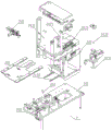
For the feeding mechanism 2 and the discharging mechanism 4, the connecting mechanism 24200 located between the feeding mechanism 2 and the discharging mechanism 4 comprises a horizontal slide rail 24260 for the crystal frame 2498 to slide; the feeding mechanism 2 and the discharging mechanism 4 can slide vertically, and the feeding mechanism 2 and the discharging mechanism 4 are provided with a material box 2399 for placing a crystal shelf 2398, as shown in the accompanying drawings 13 to 16 of the specification.
The feeding mechanism 2 and the discharging mechanism 4 both comprise a bearing platform 241, a base 242, a vertical lifting part 243 and a pushing fork 244, and in addition, the feeding mechanism also comprises a pushing plate part 245; it should be noted that the feeding mechanism 2 is similar to the blanking mechanism 4 in shape and structure, and the difference is only that the feeding mechanism 2 further includes a pushing plate portion disposed outside the vertical lifting portion 3 for pushing the rack inside the magazine to the connecting mechanism 24200. The wire-bonded crystal shelf is conveyed into a material box 2499 of the blanking mechanism 4 by a conveying part of the connecting mechanism 24200; the two magazines have the same shape and structure, regardless of the magazine of the feeding mechanism 2 or the magazine of the discharging mechanism 4.
The platform 241 may be constructed like a table, and the base 242 has a rectangular frame shape; as shown in figure 19 of the specification. The base 242 serves as a reference, the front end of the base 242 is provided with a vertical lifting part 243, and the vertical lifting part 243 can move up and down synchronously with the material box 2499, namely the vertical lifting part 243 and the material box 2499 move synchronously relative to the base 242; the pusher fork 244 can move toward the outside of the susceptor 241 relative to the susceptor 241, and further, can feed the magazine 2499 located above the susceptor 241 to the outside of the susceptor 241.
The working process is that firstly, a crystal shelf 2498 to be wire-bonded is filled in a material box 2499 of the feeding mechanism 2, the material box 2499 is positioned at the position A of the slide rail 24260, and the height of the material box 2499 is higher than that of the slide rail 24260; then the material discharging box 2499 moves downwards under the action of the vertical lifting part 243, and when the height of the crystal shelf 2498 at the bottommost end in the material box 2499 is level with that of the slide rail 24260, the vertical lifting part 243 and the material box 2499 stop running; then, the pushing plate part 245 is used for pushing the crystal shelf 2498 at the bottommost end in the magazine 2499 out to the leftmost end of the slide rail 24260, such as the left end shown in fig. 14 in the specification; then, under the action of the conveying part of the connecting mechanism 24200, the crystal frame 2498 is conveyed to the workbench, and after the wire welding is finished, the wire is conveyed into a material box 2499 of the blanking mechanism 4 by the conveying part; the crystal frame 2498 is positioned at the bottom end of a material box 2499 of the blanking mechanism 4; finally, the magazine 2499 of the discharging mechanism 4 is lowered by a certain distance by the vertical elevating portion (the vertical elevating portion is the vertical elevating portion of the discharging mechanism 4 and is different from the vertical elevating portion 243 of the feeding mechanism 2) of the magazine 2499 of the discharging mechanism 4, and the magazine 2499 of the discharging mechanism 4 is sequentially filled from bottom to top.
When the magazine 2499 of the feeding mechanism 2 has no die rack 2498 to be wire bonded, the vertical lifting portion 243 is used to deliver the empty magazine 2499 onto the carrying platform 241, and the material pushing fork 244 moves the empty magazine 2499 out of the carrying platform 241; similarly, after the magazine 2499 of the discharging mechanism 4 is full, the magazine 2499 of the discharging mechanism 4 is moved to the top of the carrier 241 by the vertical lifting portion (the vertical lifting portion is the vertical lifting portion of the discharging mechanism 4 and is different from the vertical lifting portion 243 of the feeding mechanism 2), and the empty magazine 2499 is moved out of the carrier 241 by the pushing fork (the pushing fork is the pushing fork of the discharging mechanism 4 and is different from the pushing fork 244 of the feeding mechanism 2). As shown in figures 13 to 15.
The moving direction of the pushing plate 245 is the extending direction of the slide rails 24260, and the moving direction of the pushing fork 244 is perpendicular to the extending direction of the slide rails 24260 in the same plane; the feeding mechanism 2 and the blanking mechanism 4 are symmetrically arranged relative to the connecting mechanism 24200; regarding the arrangement of the connection mechanism 24200, the conveying part may include a conveying motor 24210, a conveying screw 24220, a conveying connecting rod 24230, a first clamping arm 24240 and a second clamping arm 24250, as shown in fig. 14; the conveying motor 24210 drives the conveying screw 24220 to rotate, so that the conveying connecting rod 24230 slides along the extending direction of the slide rail 24260, a first clamping arm 24240 and a second clamping arm 24250 are fixed at two ends of the conveying connecting rod 24230, and clamping and releasing of the first clamping arm 24240 and the second clamping arm 24250 can be realized by referring to the prior art; that is, after the first clamping arm 24240 and the second clamping arm 24250 can clamp the crystal shelf 2498, the crystal shelf 2498 is moved from the position a to the position B under the action of the conveying screw 24220, and the right end of the second clamping arm 24250 is further provided with a conveying end for pushing the crystal shelf 2498 into the magazine 2499 of the blanking mechanism 4.
The vertical elevating part 243 may include a linear motor 2431 and a vertical rod 2432 connected to the linear motor 2431; the vertical bar 2432 is fixedly connected to a lifting fork 2433 for supporting the base 242, as shown in fig. 18 and 23 of the specification. The linear motor 2431 is used as a power source to drive the vertical rod 2432 to rotate, wherein the vertical rod 2432 can be a lead screw; vertical pole 2432 is located to connecting block 2434, can realize vertical motion under vertical pole 2432's rotation, and fork 2433 and connecting block 2434 fixed connection go up and down, and then accomplish and slide from top to bottom.
In the working process, the lifting fork 2433 drags the bottom of the material box 2499, so as to drive the material box 2499 to move up and down; when the lifting fork 2433 moves to the bottom, the material box 2499 is placed on the carrying platform 241, and the pushing fork 244 is located on one side of the material box 2499 close to the base 242, so that when the pushing fork 244 moves towards the outer side of the base 242, the material box 2499 can be pushed out of the carrying platform 241.
The pushing plate portion 245 may further include a pushing rod 2451 and a pushing motor 2452, and an output shaft of the pushing motor 2452 is connected to the pushing rod 2451 through sliding friction, as shown in fig. 20 and 21 in the specification.
The push plate mounting rack 2450 can be fixed on the frame of the base 242, a chute 2453 is arranged in the moving direction of the pushing rod 2451, and the pushing rod 2451 slides in the chute 2453; the cover plate 2454 can cover the pushing motor 2452, the pushing rod 2451 is located above the output shaft of the pushing motor 2452, the pushing rod 2451 and the output shaft of the pushing motor 2452 are in sliding friction, and when resistance is met during pushing of the pushing rod 2451, the pushing rod 2451 and the output shaft of the pushing motor 2452 can slip, so that the pushing rod 2451 and/or the crystal frame 2498 can be prevented from being damaged. An upper pressing wheel 2458 and a lower pressing wheel 2457 are further provided on the upper layer and the lower layer of the material pushing rod 2451, and a first guide block 2455 and a second guide block 2456 are further provided along the sliding direction of the material pushing rod 2451 to ensure the reliable sliding of the material pushing rod 2451. The front end of the material pushing rod 2451 can be provided with a V-shaped head 2451 to ensure that the pushed crystal frame 2498 is completely contacted with the material pushing rod 2451.
The feeding device of the invention also comprises a discharging plate 246 arranged on the bearing table 241, wherein the discharging plate 246 is positioned at the front end of the substrate 242; the pushing fork 244 is perpendicular to the material discharging plate 246, and the pushing fork 244 is connected to a power part 2441 for horizontally moving the pushing fork 244. The discharging plate 246 is fixed relative to the bearing table 241, and the discharging plate 246 is positioned below the lifting fork 2433; when the lifting fork 2433 moves to the bottommost end, the material box 2499 supported by the lifting fork 2433 is positioned above the material discharging plate 246; that is, the lifting fork 2433 can move to the lower part of the material placing plate 246, so that the material box 2499 supported by the lifting fork 2433 is dragged by the material placing plate 246, and then the material box 2499 on the material placing plate 246 is horizontally pushed by the material pushing fork 244. The discharge plate 246 may be provided with a plurality of transverse slots, and the discharge forks 244 may extend above the transverse slots and may be capable of moving transversely within the transverse slots, as illustrated in fig. 18, 24 and 25 of the specification.
Taking fig. 24 as an example, when the lifting fork 2433 moves to the bottom end, the magazine 2499 supported by the lifting fork 2433 is located on the material discharging plate 246, at this time, the magazine 2499 is located on the left side of the material discharging fork 244, and then the material discharging fork 244 moves to the right side, so that the magazine 2499 is pushed out of the supporting table 241.
The pushing fork 244 can be driven by a pushing motor 2441, the pushing motor 2441 is located on the left side (taking fig. 25 as an example), the right side is a driven shaft, power is transmitted between the pushing motor 2441 and the driven shaft through a belt, the belt is provided with the pushing fork 244, and a pushing guide block for limiting the pushing fork 244 can be further arranged on the belt to ensure the moving direction of the pushing fork 244. The cartridge sensing part 248 may be located at one side of the material pushing motor 2441 to detect whether the cartridge 2499 falls on the material discharging plate 246; of course, the specific arrangement of the cartridge sensing portion 248 may refer to the prior art.
Clamping parts 247 are arranged on two sides of the base 242 so as to clamp a second material box above the first material box when the vertical lifting part 243 drives the first material box to descend;
the clamping portion 247 comprises a cross bar 2470, the cross bar 2470 is fixedly connected with a first vertical front stop 2471, and the cross bar 2470 is provided with a second vertical front stop 2472 capable of sliding along the cross bar 2470; the clamping device further comprises a sliding rod 2473 which is connected with the cross rod 2470 and is positioned on the outer side of the base body 242, the sliding rod 2473 is connected with a clamping motor 2474 which is used for moving the cross rod 2470 towards the base body 242, and a fixed rear stop 2475 is further arranged between the cross rod 2470 and the base body 242. That is, the two back stoppers 2475 are fixed in position relative to the base 242, and the first vertical front stopper 2471, the second vertical front stopper 2472 and the cross bar 2470 can move toward the base 242 under the action of the sliding rod 2473 and the clamping motor 2474, that is, the gap between the second vertical front stopper 2472 and the back stopper 2475 is reduced; first vertical front stop 2471, second vertical front stop 2472, and two back stops 2475 form a cartridge channel; as can be seen from the above, the magazine 2499 is located directly above the material discharge plate 246, that is, the magazine 2499 is located in an area surrounded by the first vertical front stop 2471, the second vertical front stop 2472, the cross bar 2470 and the two rear stops 2475.
During the above process, the magazine 2499 is supported by the lifting fork 2433; however, when the cassette 2498 in the cassette 2499 is used up (for the feeding mechanism 2), the cassette 2499 (which may be called as a first cassette) without the cassette 2498 inside needs to be placed on the supporting platform 241 so as to be pushed out by the pushing fork 244; however, the second magazine (the second magazine is filled with the wafer rack 2498 to be wire bonded) above the magazine 2499 (i.e. the first magazine) needs to be kept at a certain height, and the first vertical front block 2471, the second vertical front block 2472 and the two rear blocks 2475 of the clamping portion 247 can clamp four sides of the second magazine to keep the second magazine at a preset height, so that the lifting fork 2433 firstly conveys the first magazine onto the bearing table 241, and then the lifting fork 2433 returns to the second magazine to support the second magazine, and then the first vertical front block 2471, the second vertical front block 2472 and the cross bar 2470 move forward under the action of the clamping motor 2474, that is, the distance between the cross bar 2470 and the rear block 2475 is increased, the second magazine is released, the second magazine is completely supported by the lifting fork 2433, and the above steps are repeated. Of course, first vertical forward stop 2471 may adjust the gap between first vertical forward stop 2471 and second vertical forward stop 2472 under the action of adjustment knob 2476 to accommodate cartridges of different sizes. For the shape and structure of the blanking mechanism 4, reference may be made to fig. 14, which is not described herein again.
It is noted that, in this specification, relational terms such as first and second, and the like are used solely to distinguish one entity from another entity without necessarily requiring or implying any actual such relationship or order between such entities.
The wire bonding machine provided by the invention is described in detail above. The principles and embodiments of the present invention are explained herein using specific examples, which are presented only to assist in understanding the method and its core concepts. It should be noted that, for those skilled in the art, it is possible to make various improvements and modifications to the present invention without departing from the principle of the present invention, and those improvements and modifications also fall within the scope of the claims of the present invention.
Claims (8)
1. A wire welding machine comprises a rack and is characterized by further comprising a feeding mechanism, a workbench and a discharging mechanism which are arranged on the rack and sequentially arranged along the transverse direction of the rack, wherein a microscope and a bonding head for welding wires are respectively arranged on two longitudinal sides of the workbench, and the microscope is arranged on the outer side of the workbench; the bonding head is provided with a temperature controller for controlling the temperature of the workbench, and the bonding head also comprises a wire feeder which is arranged on the bonding head and used for feeding bonding wires;
the bunding head comprises a machine body (5200), wherein the machine body (5200) is provided with a first Y-axis platform (5018) which is long in length and can move along the Y-axis direction and a second Y-axis platform (503) which is short in length and can move along the Y-axis direction, and the first Y-axis platform (5018) and the second Y-axis platform (503) are both connected with a linear sliding rail (5036) between the first Y-axis platform and the second Y-axis platform;
an X-axis platform (502) is further arranged below the second Y-axis platform (503); the X-axis platform (502) can move along the X-axis direction through an X-axis guide rail (5039), a bonding head module (5100) for welding wires is fixedly connected above the second Y-axis platform (503), and the bonding head module (5100) comprises a transducer (524) capable of rotating up and down; the top of the bonding head module (5100) is sequentially provided with a lens (5700), a lens barrel (5600), a camera (5400) and a visual positioning module (5500) which extend along the Y-axis direction;
the bonding head module (5100) further comprises a bonding head base body (56), the front end of the bonding head base body (56) is provided with a support protruding outwards, the support is provided with a flexible fulcrum (522), and the bonding head frame (53) is hinged to the flexible fulcrum (522); the transducer (524) extending towards the front end is fixedly connected to the bonding head frame (53), a fire striking rod (517) located on one side of the transducer (524) is further fixed on the bonding head frame (53), the working end of the transducer (524) is closely adjacent to the working end of the fire striking rod (517), and a voice coil motor used for rotating the bonding head frame (53) is arranged at the tail end of the bonding head frame (53);
the bonding head base body (56) is provided with a limit stop (52) used for limiting the rotation angle of the bonding head frame (53), and the limit stop (52) is positioned below the bonding head frame (53); a frame body vertical supporting column (513) is arranged below the transducer (524), and a grating scale (525) is arranged on the frame body vertical supporting column (513); a base body vertical supporting column (57) is arranged below the limit stop (52), and a grating induction sheet (523) used for inducing the rotation angle of the grating ruler (525) is arranged on the base body vertical supporting column (57).
2. The wire bonding machine of claim 1, wherein the wire feeder comprises a vertically arranged mounting plate (705), the mounting plate (705) is provided with a coil fixing seat (703) capable of horizontally rotating and a wire rod (708) positioned at one side of the coil fixing seat (703), and a wire passing module (706) fixed on the mounting plate (705) is arranged at one side of the wire rod (708) along the wire feeding direction; the wire passing module (706) is provided with a wire passing channel for a welding wire to pass through, a blowing hole (7065) for tensioning the tension of the welding wire is formed in the front end of the wire passing channel, an optical fiber detection part (7062) for detecting the swing of the welding wire is further arranged in the wire passing channel, and the optical fiber detection part (7062) is connected with a power source (709) for controlling the rotation of the coil fixing seat (703) so as to control the power source (709) to be started to realize the rotation of the coil fixing seat (703) when the optical fiber detection part (7062) detects the swing of the welding wire.
3. The wire bonding machine according to claim 1, wherein a first cross guide (5038) is arranged below the first Y-axis platform (5018), a crosspiece (5015) fixed to the first cross guide (5038) and extending in the X-axis direction is arranged above the first Y-axis platform (5018), a limiting part (5012) is arranged on one side of the crosspiece (5015), and a locking part (5027) is arranged on the other side of the crosspiece (5015).
4. The wire bonding machine of claim 3 wherein a cover plate (5019) is positioned above the linear slide (5036) and fixedly attached to the first Y-axis platform (5018).
5. The wire bonding machine of any one of claims 1-4, wherein the feeding mechanism and the blanking mechanism each comprise:
a stage (241);
a base body (242) arranged above the bearing table (241); the substrate (242) is in a rectangular frame shape;
the vertical lifting part (243) is arranged on the bearing table (241) and is connected with the base body (242) and used for downward movement of the feeding box, and the vertical lifting part (243) is positioned at the front end of the base body (242);
a pushing fork (244) arranged on the bearing platform (241) and used for pushing the material box positioned on the vertical lifting part (243) out of the vertical lifting part (243);
the feeding mechanism further comprises a pushing plate part (245) which is arranged on the outer side of the vertical lifting part (243) and used for pushing the crystal frame in the material box to the connecting mechanism.
6. The wire bonding machine of claim 5, further comprising a discharge plate (246) disposed on said carrier table (241), said discharge plate (246) being located at a front end of said base (242); the material pushing fork (244) is perpendicular to the material discharging plate (246), and a power part (2441) used for realizing horizontal moving of the material pushing fork (244) is connected to the material pushing fork (244).
7. The wire bonding machine of claim 6 wherein said feed plate (246) is provided with a plurality of transverse channels, said feed forks (244) projecting above said transverse channels and being capable of transverse movement within said transverse channels.
8. The wire bonding machine of claim 7 wherein the base (242) is flanked by clamping portions (247) to grip a second magazine above a first magazine as the first magazine is lowered by the vertical lift (243);
the clamping part (247) comprises a cross bar (2470), the cross bar (2470) is fixedly connected with a first vertical front stop (2471), and the cross bar (2470) is provided with a second vertical front stop (2472) capable of sliding along the cross bar (2470); the clamping device is characterized by further comprising a sliding rod (2473) which is connected with the cross rod (2470) and located on the outer side of the base body (242), the sliding rod (2473) is connected with a clamping motor (2474) which is used for enabling the cross rod (2470) to move towards the base body (242), and a rear stop block (2475) which is fixed in position is further arranged between the cross rod (2470) and the base body (242).
Priority Applications (1)
| Application Number | Priority Date | Filing Date | Title |
|---|---|---|---|
| CN201710537745.5A CN107160050B (en) | 2017-07-04 | 2017-07-04 | Wire bonding machine |
Applications Claiming Priority (1)
| Application Number | Priority Date | Filing Date | Title |
|---|---|---|---|
| CN201710537745.5A CN107160050B (en) | 2017-07-04 | 2017-07-04 | Wire bonding machine |
Publications (2)
| Publication Number | Publication Date |
|---|---|
| CN107160050A CN107160050A (en) | 2017-09-15 |
| CN107160050B true CN107160050B (en) | 2023-03-24 |
Family
ID=59822659
Family Applications (1)
| Application Number | Title | Priority Date | Filing Date |
|---|---|---|---|
| CN201710537745.5A Active CN107160050B (en) | 2017-07-04 | 2017-07-04 | Wire bonding machine |
Country Status (1)
| Country | Link |
|---|---|
| CN (1) | CN107160050B (en) |
Families Citing this family (5)
| Publication number | Priority date | Publication date | Assignee | Title |
|---|---|---|---|---|
| CN107870643B (en) * | 2017-10-26 | 2020-02-07 | 合肥超越电器有限责任公司 | Temperature controller of lateral hidden type lifting mechanism |
| CN109047976B (en) * | 2018-10-15 | 2021-01-05 | 唐明 | Threading welding machine |
| TWI690001B (en) * | 2018-12-07 | 2020-04-01 | 日月光半導體製造股份有限公司 | Stage apparatus, process equipment and operation method of the process equipment |
| CN110125507B (en) * | 2019-06-20 | 2021-05-07 | 深圳市晶封存储科技有限公司 | Method for welding wires on full-automatic PCBA (printed circuit board assembly) |
| CN114619183A (en) * | 2022-04-21 | 2022-06-14 | 恩纳基智能科技无锡有限公司 | Bonding head wire welding mechanism |
Citations (9)
| Publication number | Priority date | Publication date | Assignee | Title |
|---|---|---|---|---|
| CN1773688A (en) * | 2005-10-24 | 2006-05-17 | 中国电子科技集团公司第四十五研究所 | Light high-stiffness XY working platform and bonding head |
| CN101625989A (en) * | 2008-07-08 | 2010-01-13 | 深圳市大族精密机电有限公司 | Wire feeding/drawing device and method thereof |
| CN201801231U (en) * | 2010-07-30 | 2011-04-20 | 深圳市翠涛自动化设备有限公司 | Automatic setting out device for welding wire machine |
| CN202622227U (en) * | 2012-06-27 | 2012-12-26 | 邹志峰 | Stably-movable welding head installation platform of welding wire machine |
| CN203187073U (en) * | 2013-03-05 | 2013-09-11 | 深圳市森力普电子有限公司 | Feeding device |
| CN203456421U (en) * | 2013-03-01 | 2014-02-26 | 广东工业大学 | Bonding head apparatus applied to full-automatic lead bonding device |
| CN103612036A (en) * | 2013-11-13 | 2014-03-05 | 深圳市综科邦达机电设备有限公司 | Wire welding machine |
| CN204321405U (en) * | 2014-07-18 | 2015-05-13 | 宋勇飞 | Mould bar and ultrasonic wave gold wire ball bonding equipment |
| CN207205594U (en) * | 2017-07-04 | 2018-04-10 | 东莞市凯格精密机械有限公司 | A kind of bonding equipment |
Family Cites Families (1)
| Publication number | Priority date | Publication date | Assignee | Title |
|---|---|---|---|---|
| US6616030B2 (en) * | 2001-05-07 | 2003-09-09 | West Bond, Inc. | Gantry mounted ultrasonic wire bonder with orbital bonding tool head |
-
2017
- 2017-07-04 CN CN201710537745.5A patent/CN107160050B/en active Active
Patent Citations (9)
| Publication number | Priority date | Publication date | Assignee | Title |
|---|---|---|---|---|
| CN1773688A (en) * | 2005-10-24 | 2006-05-17 | 中国电子科技集团公司第四十五研究所 | Light high-stiffness XY working platform and bonding head |
| CN101625989A (en) * | 2008-07-08 | 2010-01-13 | 深圳市大族精密机电有限公司 | Wire feeding/drawing device and method thereof |
| CN201801231U (en) * | 2010-07-30 | 2011-04-20 | 深圳市翠涛自动化设备有限公司 | Automatic setting out device for welding wire machine |
| CN202622227U (en) * | 2012-06-27 | 2012-12-26 | 邹志峰 | Stably-movable welding head installation platform of welding wire machine |
| CN203456421U (en) * | 2013-03-01 | 2014-02-26 | 广东工业大学 | Bonding head apparatus applied to full-automatic lead bonding device |
| CN203187073U (en) * | 2013-03-05 | 2013-09-11 | 深圳市森力普电子有限公司 | Feeding device |
| CN103612036A (en) * | 2013-11-13 | 2014-03-05 | 深圳市综科邦达机电设备有限公司 | Wire welding machine |
| CN204321405U (en) * | 2014-07-18 | 2015-05-13 | 宋勇飞 | Mould bar and ultrasonic wave gold wire ball bonding equipment |
| CN207205594U (en) * | 2017-07-04 | 2018-04-10 | 东莞市凯格精密机械有限公司 | A kind of bonding equipment |
Also Published As
| Publication number | Publication date |
|---|---|
| CN107160050A (en) | 2017-09-15 |
Similar Documents
| Publication | Publication Date | Title |
|---|---|---|
| CN107160050B (en) | Wire bonding machine | |
| US8522423B2 (en) | Method and device for feeding and attaching corrective elements for unbalance correction, in particular in a balancing machine | |
| JP6284540B2 (en) | Electronic component mounting device | |
| KR101518025B1 (en) | Apparatus for welding motor controller parts | |
| JP7220035B2 (en) | band saw | |
| CN109702283B (en) | Full-automatic welding pressure-sensitive machine | |
| CN102412492A (en) | Automatic processing device for DC (direct current) plug | |
| JP6259464B2 (en) | Electronic component mounting device | |
| CN113241571A (en) | Automatic welding equipment for wires | |
| CN210451293U (en) | Automatic tin soldering device for inductor production | |
| CN113714632A (en) | Circular saw blade laser welding equipment | |
| JP2017069502A (en) | Stick feeder and component mounting device | |
| CN207205594U (en) | A kind of bonding equipment | |
| CN210615463U (en) | Magnetic fixing and guiding device for automatic submerged arc welding | |
| CN109048534A (en) | A kind of automotive brake pads chamfering at two sides machine | |
| CN211310120U (en) | Automatic feeding mechanism for machining | |
| CN115971602A (en) | Automatic brazing device for integrated circuit board | |
| CN105681997B (en) | A kind of earphone automatic welding device and method | |
| CN209998268U (en) | kinds of trimming outlet device | |
| CN207057830U (en) | A kind of bonding equipment and its bonding wire control system | |
| CN216298217U (en) | Welding equipment for ceramic heating body pins | |
| CN211804280U (en) | Automatic soldering tin equipment | |
| CN108941874A (en) | A kind of transmission device | |
| CN212634868U (en) | Welding sliding table | |
| CN210824393U (en) | Feeding clamping jaw and feeding device |
Legal Events
| Date | Code | Title | Description |
|---|---|---|---|
| PB01 | Publication | ||
| PB01 | Publication | ||
| SE01 | Entry into force of request for substantive examination | ||
| SE01 | Entry into force of request for substantive examination | ||
| CB02 | Change of applicant information |
Address after: 523000 2 Sha long road, Dongcheng Street, Dongguan, Guangdong Applicant after: Dongguan Kaige Precision Machinery Co.,Ltd. Address before: 523000 Guangdong city of Dongguan province Dongcheng District Sharon Road No. 2 Applicant before: GKG PRECISION MACHINE Co.,Ltd. |
|
| CB02 | Change of applicant information | ||
| GR01 | Patent grant | ||
| GR01 | Patent grant |