This application is a non-provisional patent application of U.S. provisional patent application No. 61/903,726 filed 2013, 11, 13, the disclosure of which is incorporated herein by reference in its entirety and for the benefit of this disclosure.
Detailed Description
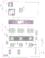
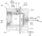
Referring to fig. 1A through 1D, schematic diagrams of a substrate processing apparatus or tool incorporating aspects of the disclosed embodiments as further disclosed herein are shown. Although aspects of the disclosed embodiments will be described with reference to the drawings, it should be understood that aspects of the disclosed embodiments can be embodied in many forms. In addition, any suitable size, shape or type of elements or materials could be used.
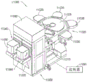
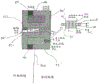
Referring to fig. 1A and 1B, a processing apparatus, e.g., a semiconductor tool station 11090, is shown in accordance with aspects of the disclosed embodiments. Although a semiconductor tool is shown in the figures, the aspects of the disclosed embodiments described herein can be applied to any tool station or application that employs a robotic manipulator. In this example, the Tool 11090 is shown as a cluster Tool, however, aspects of the disclosed embodiments may be applied to any suitable Tool station, such as a linear Tool station (e.g., the linear Tool station in U.S. patent No. 8, 398, 355 entitled "linear distributed Semiconductor Workpiece Processing Tool", shown in fig. 1C and 1D and described in 2013, 3, 19, the disclosure of which is incorporated herein by reference in its entirety). The tool station 11090 generally includes an atmospheric front end 11000, a vacuum load lock 11010, and a vacuum back end 11020. In other aspects, the tool station can have any suitable configuration. The components of each of the front end 11000, the load lock 11010, and the back end 11020 may be connected to a controller 11091, which may be part of any suitable control architecture (e.g., clustered architecture control). The Control System may be a closed-loop controller having a master controller, a cluster controller, and an autonomous remote controller (e.g., the controller described in U.S. patent No. 7,904,182 entitled "Scalable Motion Control System," issued 3/8/2011, the disclosure of which is incorporated herein by reference in its entirety). In other aspects, any suitable controller and/or control system may be utilized.
In one aspect, the front end 11000 generally includes a load port module 11005 and a mini-environment 11060, e.g., an Equipment Front End Module (EFEM). The load port module 11005 may be a case opener/case packer-tool standard (BOLTS) interface that conforms to SEMI standards E15.1, E47.1, E62, E19.5, or E1.9 for 300 mm load ports, front opening or bottom opening cassettes/cases, and boxes. In other aspects, the load port module may be configured as a 200 mm silicon die interface or any other suitable substrate interface (e.g., larger or smaller silicon die or flat panel for flat panel displays). Although two load port modules are shown in fig. 1A, in other aspects any suitable number of load port modules may be incorporated into the front end 11000. The load port module 11005 may be configured to receive substrate carriers or cassettes 11050 from an overhead transport system, an automated guided vehicle, a human guided vehicle, a rail guided vehicle, or from any other suitable transport method. The load port modules 11005 may interface with the mini-environment 11060 through load ports 11040. The load port 11040 may allow substrates to pass between the substrate cassette 11050 and the mini-environment 11060. The mini-environment 11060 generally includes any suitable transfer robot 11013 that may incorporate one or more aspects of the disclosed embodiments described herein. In one aspect, the robot 11013 may be a rail mounted robot, such as the rail mounted robot described in, for example, U.S. patent 6, 002, 840, the disclosure of which is incorporated herein by reference in its entirety. The mini-environment 11060 may provide a controlled denuded zone to transfer substrates between multiple load port modules.
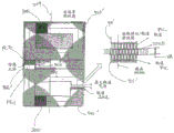
The vacuum load lock 11010 may be located between the mini-environment 11060 and the rear end 11020 and be connected to the mini-environment 11060 and the rear end 11020. It should be noted that the term vacuum as used herein may refer to a high vacuum in which substrates are processed, e.g., 10-5Hold or below. The load lock 11010 generally includes an atmospheric slot valve and a vacuum slot valve. The slot valve may provide environmental isolation to evacuate the load lock after loading the substrate from the atmospheric front end and to maintain a vacuum in the transfer chamber while venting the lock with an inert gas (e.g., nitrogen). The load lock 11010 may also include an aligner 11011 for aligning a fiducial of the substrate to a desired position for processing. In other aspects, the vacuum load lock may be located in any suitable location and have any suitable configuration of the processing apparatus.
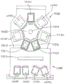
The vacuum back end 11020 generally includes a transport chamber 11025, one or more processing stations 11030, and any suitable handling robot 11014, which may include one or more aspects of the disclosed embodiments described herein. The transfer robot 11014 will be described below and may be located within the transport chamber 11025 to transport substrates between the load lock 11010 and the various processing stations 11030. The processing stations 11030 may operate on the substrate through various deposition, etching, or other types of processes to form circuits or other desired structures on the substrate. Typical processes include, but are not limited to, thin film processes using vacuum, such as plasma etching or other etching processes, Chemical Vapor Deposition (CVD), Plasma Vapor Deposition (PVD), implantation (e.g., ion implantation), metrology, Rapid Thermal Processing (RTP), dry lift-off Atomic Layer Deposition (ALD), oxidation/diffusion, nitride formation, vacuum lithography, Epitaxy (EPI), wire bonder and evaporation or other thin film processes using vacuum pressure. The processing stations 11030 are connected to the transport chamber 11025 to allow substrates to be transferred from the transport chamber 11025 to the processing stations 11030 and vice versa.
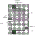
Referring now to fig. 1C, a schematic plan view of a linear substrate processing system 2010 is shown with the tool interface section 2012 mounted to the transport chamber module 3018 such that the interface section 2012 is generally facing (e.g., inward of) the transport chamber 3018 but offset from its longitudinal axis X. The transfer chamber module 3018 may be extended in any suitable direction by attaching other transfer chamber modules 3018A, 3018I, 3018J to the interfaces 2050, 2060, 2070, as described in U.S. patent No. 8, 398, 355, previously incorporated by reference herein. Each transfer chamber module 3018, 3019A, 3018I, 3018J includes any suitable substrate transport 2080, which may include one or more aspects of the disclosed embodiments described herein, for transporting substrates into and out of, for example, process modules PM throughout processing system 2010. As can be appreciated, each chamber module may be capable of maintaining an isolated or controlled atmosphere (e.g., N2, clean air, vacuum).
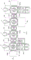
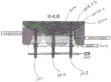
Referring now to fig. 1D, a schematic front view of an exemplary processing tool 410 is shown, for example, as may be taken along a longitudinal axis X of a linear transport chamber 416. In aspects of the disclosed embodiment shown in fig. 1D, the tool interface section 12 may representatively connect to the transport chamber 416. In this aspect, the interface section 12 may define one end of the tool delivery chamber 416. As seen in fig. 1D, the transfer chamber 416 may have an additional workpiece entrance/exit station 412, for example, at an end opposite the interface station 12. In other aspects, other entry/exit stations for inserting/removing workpieces from the transport chamber may be provided. In one aspect, the interface section 12 and the entry/exit station 412 may allow for loading and unloading of workpieces from the tool. In other aspects, the workpiece may be loaded into the tool from one end and removed from the other end. In one aspect, the transfer chamber 416 may have one or more transfer chamber modules 18B, 18 i. Each chamber module may be capable of maintaining an isolated or controlled atmosphere (e.g., N2, clean air, vacuum). As previously mentioned, the configuration/arrangement of the transfer chamber modules 18B, 18i, load lock modules 56A, 56B, and workpiece stations forming the transfer chamber 416 shown in fig. 1D is merely exemplary, and in other aspects, the transfer chamber may have more or fewer modules disposed in any desired modular arrangement. In the aspect shown, the station 412 may be a load lock. In other aspects, the load lock module may be located between end entrance/exit stations (similar to station 412), or an adjacent transfer chamber module (similar to module 18 i) may be configured to operate as a load lock. As also previously described, the transport chamber modules 18B, 18i have one or more corresponding transport apparatuses 26B, 26i located therein, which may include one or more aspects of the disclosed embodiments described herein. The transport apparatus 26B, 26i of the representative transport chamber modules 18B, 18i may cooperate to provide a linear distributed workpiece transport system 420 in the transport chamber. In this aspect, the transport apparatus 26B may generally have a SCARA arm configuration, but in other aspects the transport arm may have any other desired arrangement, such as a frog-leg configuration, a telescoping configuration, a bi-symmetric configuration, or the like. In aspects of the disclosed embodiment shown in fig. 1D, the arms of transport apparatus 26B may be arranged to provide what may be referred to as a rapid exchange arrangement, allowing the transport to rapidly exchange silicon wafers from the pick/place location, as will also be described in further detail below. The transport arm 26B may have suitable drive sections (e.g., described below) for providing any suitable number of degrees of freedom to each arm (e.g., independent rotation about shoulder, elbow, and Z-axis motion). As seen in fig. 1D, in this aspect, the modules 56A, 56, 30i may be located intermediately between the transfer chamber modules 18B, 18i, and may define suitable processing modules, load locks, buffer stations, metrology stations, or any other desired stations. For example, the interposed modules (e.g., load locks 56A, 56 and workpiece station 30 i) may each have a fixed workpiece support/workpiece rack 56S, 56S1, 56S2, 30S1, 30S2 that may cooperate with a transfer arm to effect transfer of workpieces along the linear axis X of the transfer chamber through the length of the transfer chamber. By way of illustration, one or more workpieces may be loaded into the transport chamber 416 by the interface section 12. The interface section's transfer arm 15 may be used to position the workpiece on one or more supports of the load lock module 56A. One or more workpieces in the load lock module 56A may be moved between the load lock module 56A and the load lock module 56 by the transfer arm 26B in module 18B, and between the load lock 56 and the workpiece station 30i in a similar and continuous manner using arm 26i (in module 18 i), and between the station 30i and the station 412 using arm 26i in module 18 i. This process may be reversed, in whole or in part, to move one or more workpieces in opposite directions. Thus, in one aspect, the workpiece may be moved in any direction along the axis X and to any position along the transport chamber, and may be loaded to and unloaded from any desired (process or otherwise) module in communication with the transport chamber. In other aspects, no intervening transfer chamber module with static workpiece supports or workpiece racks may be provided between the transfer chamber modules 18B, 18 i. In such aspects, the transfer arms of adjoining transfer chamber modules may accomplish the transfer of the workpiece directly from the end effector or one transfer arm to the end effector of another transfer arm to move the workpiece through the transfer chamber. The processing station modules may operate on the substrate through various deposition, etching, or other types of processes to form circuits or other desired structures on the substrate. The processing station module is connected to the transport chamber module to allow substrates to be transferred from the transport chamber to the processing station and vice versa. Suitable examples of processing tools having similar general features to the processing apparatus depicted in fig. 1D are described in U.S. patent No. 8, 398, 355, which was previously incorporated herein by reference in its entirety.
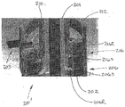
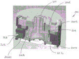
Referring now to fig. 2A, a schematic illustration of a portion of a transport apparatus driver 200 is illustrated. The transport drive may be employed in any suitable atmospheric or vacuum robotic transport (e.g., a transport of the type described above). The driver may include a driver housing 200H having at least one drive shaft 201 at least partially disposed therein. Although one drive shaft is illustrated in fig. 2A, in other aspects, the drive may include any suitable number of drive shafts. The drive shaft 201 may be mechanically suspended or magnetically suspended within the housing 200H in any suitable manner. In this aspect, the drive shaft is suspended within the housing using any suitable bearing 200B, but in other aspects the drive shaft may be magnetically suspended (e.g., a self-supporting drive) in a manner generally similar to that described in U.S. patent No. 8, 283, 813 entitled "robotic drive with Magnetic spindle bearings" (issued on 9/10/2012), the disclosure of which is incorporated herein by reference in its entirety. Each drive shaft of drive 200 may be driven by a respective motor 206, where each motor includes a stator 206S and a rotor 206R. The exemplary embodiments depicted in the figures have a configuration that may be referred to as a rotary drive configuration (which is illustrated for ease of description purposes) and features of the various aspects as shown and described herein. As can be appreciated, the features of the various aspects described with respect to the rotary drive configuration are equally applicable to the linear drive configuration. It should be noted that the drive motor described herein may be a permanent magnet motor, a variable reluctance motor (having: at least one salient pole with a corresponding coil unit; and at least one corresponding rotor with at least one salient pole of a magnetically permeable material), or any other suitable drive motor. One or more stators 206S may be at least partially secured within the housing, and one or more rotors 206R may be secured to respective drive shafts 201 in any suitable manner. In one aspect, the one or more stators 206S may be located in an "external" or "unsealed" environment that is sealed from the atmosphere in which the one or more robotic arms 208 operate (the atmosphere in which the robotic arms operate is referred to herein as a "sealed" environment, which may be a vacuum or any other suitable environment) by employing a dividing wall or barrier, while the one or more rotors 206R are located within the sealed environment in a manner generally similar to that described in U.S. provisional patent entitled "sealed robotic DRIVE" (sealed robotic DRIVE), attorney docket No. 014390P 939-US (- #1), filed 11, 13, 2013, the disclosure of which is incorporated herein by reference in its entirety and described in greater detail below. It should be noted that the term non-ferromagnetic partition wall, sealed partition or partition wall (which will be described in more detail below) as used herein refers to a wall made of any suitable non-ferromagnetic material that may be disposed between a movable portion of the robotic drive and/or sensor and a corresponding fixed portion of the robotic drive and/or sensor.
In one aspect, the housing 200H of the drive 200 has a generally drum-like configuration (e.g., a drum structure) having an outer portion 200HE and an inner portion 200 HI. In one aspect, the housing 200H is a unitary, one-piece, unitary structure, while in other aspects, the housing 200H is a unitary assembly having two or more rings secured together in any suitable manner to form a drum structure of the housing 200H. The interior 200HI of the housing includes a stator interface surface 200HS on which a stator 206S of the variable reluctance motor 206 is located. The stator interface surface 200HS (and thus the housing 200H) is configured to provide rigidity and support to the stator 206S. As can be appreciated, the stator interface surface 200HS (and thus the housing 200H) is a datum surface that positions the stator 206S (and the partition wall 204, which in one aspect is supported by the stator such that the stator is located in an atmospheric environment separate from the vacuum environment in which the rotor is located) to control the gap between the stator 206S and the rotor 206R. Housing 200H also includes a rotor interface surface 200HR that interfaces with rotor 206R and positions rotor 206R (e.g., bearing 200B is positioned on drive shaft 201/rotor 206R in a predetermined position, and bearing 200B interfaces with rotor interface surface 200 HR) such that rotor 206R is positioned in a predetermined position relative to stator 206S. As can be appreciated, the stator interface surface 200HS is a datum surface for the rotor interface surface 200HR (and thus the rotor 206R/drive shaft 201) such that the rotor 206R (and drive shaft 201 connected thereto) and the stator 206S are positioned relative to and suspended from a common datum formed by the housing 200H. In one aspect, the housing 200H includes a control board aperture or slot PCBS formed in the housing 200H in which one or more printed circuit boards PCBS (similar to the PCB 310 described below, which includes the sensor 203 connected to the sensor or encoder track 202 described below) are located in an atmospheric environment and separated from the sensor track 202 (which is located in a vacuum environment) by a vacuum barrier in a manner similar to that described below. The control board aperture PCBS includes a sensor interface surface 200HT that positions the sensor 203 in a predetermined position relative to the stator interface surface 200HS (e.g., a common reference of the housing 200H). As can be appreciated, sensor track 202 is connected to rotor 206R such that sensor track 202 is located in a predetermined position relative to rotor interface surface 200 HR. Thus, the relative positioning of sensor interface surface 200HT and rotor interface surface 200HR to stator interface surface 200HS can position and control the gap between sensor 203 and sensor track 202, where stator 206S, rotor 206R, sensor 203, and sensor track 202 are positioned relative to and suspended from a common reference. In one aspect, the housing 200H includes any suitable slot or aperture MLS through which any suitable drive connector CON passes for providing power and control signals to the driver 200 (and feedback signals from the driver 200).
With reference to fig. 2K, it should be understood that although fig. 2G-2J illustrate a drive having a single drive shaft 201 for exemplary purposes only, in other aspects the drive includes any number of motors having any suitable corresponding number of drive shafts. For example, fig. 2K illustrates a drive 200 "having two motors 206A, 206B arranged in a stacked or in-line configuration. Here, each motor 206A, 206B includes a respective housing 200H (substantially similar to the housings described above), where the housings are connected to one another in any suitable manner to form a multi-motor (e.g., multi-degree of freedom) drive 200 "such that the drive shaft 201 of the motor 206B extends through an aperture in the drive shaft 201A of the motor 206A to form a coaxial drive spindle.
Referring also to fig. 2B, a conveyor drive 200' is illustrated that is generally similar to drive 200, having a coaxial drive shaft arrangement with two drive shafts 201, 210. In this aspect, drive shaft 201 is driven by motor 206 (having stator 206S and rotor 206R), while shaft 210 is driven by motor 216 (having stator 216S and rotor 216R). Here, the motors are shown in a stacked arrangement (e.g., inline and arranged one above the other or one in front of the other). However, it should be understood that the motors 206, 216 may have any suitable arrangement, such as, for example, a side-by-side or concentric arrangement. For example, referring to fig. 2D, in one aspect, the Substrate transport Apparatus 100 is shown as having a low profile planar or "pancake" type Robot drive configuration in which the Motors are concentrically nested within one another in a manner generally similar to that described in U.S. patent No. 8, 008, 884 entitled "Substrate Processing Apparatus with motor integrated to Chamber Walls" (issued at 30.8.2011) and U.S. patent No. 8, 283, 813 entitled "Robot drive with Magnetic Spindle bearing" (issued at 9.10.2012), the disclosures of which are hereby incorporated by reference in their entirety. The substrate transport apparatus 100 may include a magnetoresistive drive 100D having one or more stators and corresponding rotors (in this aspect, the rotors include an outer rotor 101 and an inner rotor 102). The rotors 101, 102 may be actuated by their respective stators through the enclosing or separating wall 103 based on any suitable reluctance motor principle. It should be noted that a pancake-type drive configuration may provide a direct drive to replace a harmonic drive robot for high/heavy payload applications due to, for example, relatively large rotor diameters and high torque capabilities. In other aspects, any suitable harmonic drive may be coupled to the output of the motors described herein for driving one or more robotic arms. The pancake-type drive configuration may also allow for a hollow central drive section that can accommodate the vacuum pump inlet and/or support the vacuum pumping arrangement to be partially or fully integrated into the robot drive, for example in a compact vacuum chamber (where the space around the robot drive is limited) or any other suitable chamber (in which the robot drive is at least partially disposed).
The drives described herein may carry any suitable robotic arm 104 (as described above) configured to transport, for example, a semiconductor silicon wafer, a flat panel for a flat panel display, a solar panel, a reticle (reticles), or any other suitable payload. In this aspect, the robotic arm 104 is illustrated as a double-symmetric robotic arm (e.g., having opposing end effectors coupled to extend and retract), with one of the upper arms 104U1, 104U1' attached to the outer rotor 101 and the other upper arm 104U2, 104U2 ″ attached to the inner rotor 102. In other aspects, any suitable number and type of robotic arms may be attached to the drive motor arrangements described herein. In addition to the doubly-symmetric arm 104, other examples of arm configurations that may be employed with pancake-type or stacked motor arrangements include, but are not limited to, the arm configuration described in U.S. patent application No. 12/117,415 entitled "substrate transport apparatus with Multiple Movable Arms Utilizing a Mechanical switch mechanism" (filed on 8.5.2008), the disclosure of which is incorporated by reference herein in its entirety. For example, the arm may be derived from a conventional SCARA (selective compliance articulated robotic arm) type design, which includes an upper arm, a forearm with drive, and an end effector with restraint, as well as from a telescoping arm or any other suitable arm design by omitting the upper wall.
The operation of the arms may be independent of each other (e.g., extension/retraction of each arm is independent of the other arms), may be operated by a lost motion switch, or may be operably coupled in any suitable manner such that the arms share at least one common drive axis. As an example, the radially extending movement of either end effector 104E1, 104E2 of a double symmetric arm may be performed by rotating outer rotor 101 and inner rotor 102 substantially simultaneously in opposite directions and at substantially the same rate. Rotation of arm 104 as a unit can be performed by rotating outer rotor 101 and inner rotor 102 in the same direction at substantially the same rate.
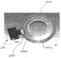
Referring again to fig. 2A and 2B and also to fig. 2C, each drive shaft 201 may also have a sensor or encoder track 202 mounted thereto having a position determining marker or feature connected with a sensor 203. It should be noted that the sensors described herein may be configured such that the readhead portion of the sensor 203 (e.g., the portion of the sensor where the sensing components are mounted) is a module that can be inserted into and removed from the driver housing or bulkhead 204 (note that the bulkhead 204 may be a common bulkhead that also isolates the driver stator from the sealed environment). The sensor 203 may be at least partially secured within the housing 200H in any suitable manner, allowing a sensing element or member 203H of the sensor 203 to read or otherwise be acted upon by one or more scales 202S (which will be described below) for providing a position signal to any suitable controller (e.g., the motion controller 190) (which may be substantially similar to the controller 11091 described above). In one aspect, at least a portion of the sensor 203 can be located in an external environment and isolated or otherwise isolated from the sealed environment using the isolation wall 204 (as will be described in more detail below) such that the sensor electronics and/or magnet are disposed in the external environment while the sensor track is disposed in the sealed environment. It may be difficult to directly monitor the sealed environment due to, for example, harsh environmental conditions (e.g., a vacuum environment or an environment with extreme temperatures). Aspects of the disclosed embodiments described herein provide for non-invasive position measurement of a moving object (e.g., a motor rotor, a robotic arm connected to a motor, or any other suitable object) within a sealed environment.
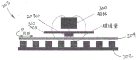
In one aspect, referring to fig. 3, the sensor 203 can utilize magnetic circuit principles to detect the position of the encoder track 202, wherein the encoder track has at least one encoder scale located within a sealed environment (e.g., wherein each of the at least one encoder scale has a predetermined pitch that may be different from the pitch of the other of the at least one encoder scale). The magnetic sensing system illustrated in fig. 3 is shown in a representative manner and may be configured as a giant magnetoresistive sensor (GMR) or a differential GMR (i.e. sensing gradient field differentials between several locations, otherwise known as gradiometers), as will be described below. The sensor may include at least one magnetic or ferromagnetic source 300, a ferromagnetic encoder track 202, and at least one magnetic sensing element or member 203H (corresponding to each magnetic source) disposed generally between the magnetic source and the ferromagnetic track.
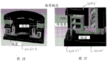
The encoder track may be configured such that the track width (e.g., the track face having the coding features thereon) may extend in a radially outwardly extending plane, with the position coding features varying orthogonally (e.g., up and down) from the track plane, as depicted in fig. 2A. In other aspects, the track width may be disposed in an axial direction parallel to the drive axis (e.g., in a rotary drive configuration, the track faces form a circle or cylinder about the drive axis T, as in a "drum" shape, such as the tracks 202S1', 202S2', 202S3' of fig. 2E-2F), with the coding features projecting radially (for rotary drives) or laterally from the track plane. In this aspect, the at least one magnetic sensing member 203H can have a substantially flat (or otherwise non-suspended feature) track interface that is substantially directly connected with the track 202, but in other aspects, as described below, the at least one magnetic sensor can be connected to a ferromagnetic member that includes a ferromagnetic feature that connects with a corresponding feature on the track. In one aspect, the magnetic source and the at least one sensing member 203H may be mounted to or otherwise integrally formed on a Printed Circuit Board (PCB) 310, wherein the printed circuit board is a common circuit board (e.g., common to each of the magnetic source and the at least one sensing member). In other aspects, each magnetic source and sensing member may be mounted to one or more respective printed circuit boards. In one aspect, the magnetic source 300 may be a permanent magnet located within an external environment. In other aspects, the magnetic source 300 can be any suitable source, such as a coil configured to be energized to generate a magnetic field. In one aspect, a magnetic field (e.g., the field lines illustrated in fig. 3) generated by the magnetic source exits the north pole N of the source 300 (e.g., the pole facing away from the track, in other aspects the magnetic pole may have any suitable orientation) (or in a direction determined by the flow of current through the coil if the coil is energized), may propagate as shown, i.e., traverse the PCB 310 and flow across the gap (e.g., between the sensing member 203H and the track 202), through the non-ferrous spacer wall 204, to the ferromagnetic track 202, and back to the opposite pole S of the magnetic source 300. One or more magnetic field distributions are generated as the ferromagnetic track moves relative to the magnetic source 300. The magnetic field distribution may have the general shape of one or more of a sine wave or a cosine wave. The sensing member 203H is configured to detect changes in magnetic flux that are associated with ferromagnetic orbital motion (e.g., magnetic field distribution).
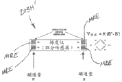
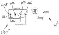
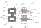
In one aspect, the one or more sensing members 203H can be any suitable Giant Magnetoresistance (GMR) sensing element/member capable of sensing a magnetic field in one or more locations. In other aspects, the one or more sensing members can be any suitable sensing element capable of sensing a magnetic field. In one aspect, the sensing member 203H can be configured to generate a sinusoidal signal that can be used to provide a phase angle associated with the incremental (and/or absolute) position of the ferromagnetic track 202, for example. In another aspect, referring to fig. 4A and 4B, the one or more sensing components can be differential Giant Magnetoresistance (GMR) sensing components (e.g., gradiometers) configured to sense a gradient field between two locations in space. The magnetic sensing system may be a gradiometer as previously described. In a gradiometer configuration, the analogue output signal of each sensing member may be proportional to the magnetic field gradient between two points in space. FIG. 4A illustrates a representative gradiometer sensing member 203H' that includes a magnetoresistive element MRE that can be configured to form, for example, a Wheatstone bridge that can affect the differential encoder channels. As can be appreciated, the arrangement of MREs (e.g., R1-R4) on the gradiometer sensing member may be characteristic of the encoding features and magnetic sources on the encoder track. FIG. 4B illustrates an exemplary gradiometer sensing member 203H ″ that includes magnetoresistive elements MRE arranged to provide two differential signals (e.g., sine/cosine) in accordance with another aspect of the disclosed embodiments. The track pitch P (fig. 3) and the position of the magnetoresistive element MRE on the sensor members 203H, 203H ', 203H ″ can be matched such that a differential sine output and a cosine output are obtained from each sensor member 203H, 203H', 203H ″.
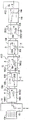
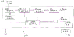
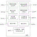
Referring to fig. 5, a schematic diagram of a driver position determination circuit in accordance with aspects of the disclosed embodiments is shown. The position determination circuitry may be integrated into a single printed circuit board or otherwise packaged as desired. In one aspect, the printed circuit board 310 (see fig. 5) may include one or more sensing members 503H (substantially similar to one or more of the above-described sensing members 203H, 203H', 203H ″ that may be integrated onto a single chip), an error compensation unit 506, a signal conditioning unit 501, a data sampling unit 502, a decoding unit 507, a propagation unit 504, and a control and synchronization unit 505 (referred to herein as a "control unit"). The functional units are shown and described separately for simplicity but may be arranged and combined in circuits as desired. In other aspects, the printed circuit board 310 can have any suitable configuration for implementing position sensing as described herein.
The control and synchronization unit 505 may include any suitable modules for performing the sensor functions described herein. For example, referring also to fig. 5C, the control and synchronization unit 505 may include one or more analog-to-digital converter modules 505A (oversampling), 505E (static time), 505F (orbit), an absolute position decoding module 505B, a sensor hysteresis compensation module 505C, a temperature compensation module 505D, an automatic orbit alignment calibration module 505G, an output protocol module 505H, and an automatic amplitude, offset, and phase calibration module 505I. As can be appreciated, although the modules 505A-505I are described as being integrated with the control and synchronization unit 505, in other aspects the modules 505A-505I may be mounted to the circuit board 310 or integrated within the circuit board 310 so as to be accessible by the control and synchronization unit 505. For example, modules 505A-505I may be integrated into one or more of functional units 501, 502, 504, 503, 507, or into any other suitable component of circuit board 310 sense circuitry. In still other aspects, the modules 505A-505I may be mounted "off-board" of the circuit board 310, such as in any suitable controller, but accessible by the control and synchronization unit 505. The oversampling analog-to-digital converter module 505A may be configured to oversample the sensor readings as described herein (at any desired configurable sampling rate) to improve noise immunity. The analog-to-digital converter module 505E may be configured to sample the sensor signal at "quiet times" as described herein to avoid noise events within the sensor loop. Analog-to-digital converter module 505F may be configured to provide on-board analog-to-digital conversion of orbit data (e.g., position feedback data) and allow for improved signal integrity while avoiding the need for long interconnection cables between the position feedback and external controllers. Absolute position decoding module 505B may be configured to allow the absolute position of the sensor to be identified at power-up or at any other desired time so that the incremental position can be properly aligned to a true absolute position. The sensor hysteresis compensation module 505C may be configured to minimize the hysteresis inherent to the sensor 503H at any suitable position corresponding to one or more of the motor position or the robotic arm position. Temperature compensation module 505D may be configured to allow for compensation of temperature effects and may include any suitable temperature lookup table. The automatic track alignment calibration module 505G may be configured to use, for example, software calibration to identify a common origin between different tracks 202, thus relaxing the tolerance of the sensor locations in the circuit board 310 relative to the various tracks 202. The output protocol module 505H may be configured to provide substantially universal integration with different types of controllers using different communication protocols.
As can be appreciated, the one or more sensing members 503H can generate raw analog signals (sine and/or cosine signals) that reflect the topology of the corresponding scale 202S on the ferromagnetic track 202 (fig. 2C). The error compensation unit 506 may be configured to appropriately address any limitations corresponding to the selected sensing technology (which in this case may be a GMR sensing technology or any suitable sensing technology). Examples of such limitations may include signal distortion due to sensor nonlinearity and saturation, as well as temperature drift effects and external magnetic field perturbations. The error compensation may be performed as needed (e.g., with commands from the control and synchronization unit 505 to the error compensation unit 506) or at any other suitable predetermined time. The signal conditioning unit 501 may be configured to scale (or otherwise calibrate-examples of which are normalization of sinusoidal amplitudes and elimination of offsets) the raw analog signal from the sensing member 503H to a value within a deterministic range. The data sampling unit 502 may be any suitable converter (e.g., an analog-to-digital converter) configured to convert the conditioned signal into raw digital data to be processed by any suitable controller (e.g., the controller described herein). The decoding unit 503 may be configured to process the raw digital data generated by the data acquisition unit 502 and convert the raw digital data into position output data. It should be noted that if an absolute position is desired, the absolute position can be obtained from analyzing data from the plurality of scales 202S on the ferromagnetic track 202, as will be described below. The propagation unit 504 may be configured to transmit the position output data to an external device, e.g., any suitable motion controller 190 (which is communicatively connected to at least one sensor from which the control and synchronization unit 505 receives sensor signals and is suitably configured to control changes in at least predetermined characteristics of the sensor signals, as listed below, in response to communications from the motion controller). The propagation unit 504 may also be configured to provide input information from the motion controller 190 that may be used by the control and synchronization unit 505 to implement timing and scheduling as will be described below.
The control and synchronization unit 505 may be configured to manage and schedule the individual functional units 503H, 501, 502, 504, 506, 507 as shown in fig. 5. As described above, the individual functional units 503H, 501, 502, 504, 506, 507 and the control and synchronization unit 505 may be integrated into a single position feedback module that can be installed in and removed from, for example, any suitable motor as a unit or a single module. In an aspect, the position feedback module may be calibrated in any suitable manner (fig. 5B, block 589). Since the relationship between the sensing units is known, for example, calibration may be performed on a test bench, for example, under "off-board" conditions of the motor (e.g., when not installed in the motor). For example, any suitable software calibration may be performed such that the position feedback module as a whole is calibrated (e.g., such that the module is ready for operation) and installed in an off-board condition. With the position feedback module in place (e.g., onboard the motor), a final alignment calibration between the one or more sensing units 503H and the respective rails 202 may be performed (e.g., automatically using an onboard automatic rail calibration module 505G). In other aspects, the motion controller 190 may be configured to manage and schedule the individual functional units 503H, 501, 502, 504, 506, 507 in a manner substantially similar to that described below with respect to the control and synchronization unit 505. In still other aspects, management and scheduling of the individual functional units may be shared between the control and synchronization unit 505 and the motion controller 190. For example, the error compensation unit 506 can be enabled by the control and synchronization unit 505 at any suitable time (e.g., as needed) to improve the accuracy and reproducibility of the sensing member 503H signal output. The signal conditioning unit 501 may also be controlled by the control and synchronization unit 505 to normalize the analog signal substantially automatically upon request by the control and synchronization unit 505 or at any other suitable time. The data sampling unit execution can also be controlled by the control and synchronization unit 505 such that the position data is sampled at a "static" time, where the sensing loop is not subject to transients, or at any other suitable time. The control and synchronization unit 505 may also be configured to define oversampling parameters to improve the quality of data from the data sampling unit 502. The oversampled data may be obtained at any suitable time (e.g., during a "static time" as described herein). The control and synchronization unit 505 may also perform position calculations by sending one or more commands to the decoding unit 507 when appropriate sample data is available. The control and synchronization unit 505 may also be configured to control the propagation unit 504 such that the final decoding position is output at a predetermined time.
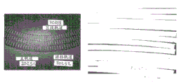
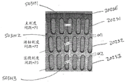
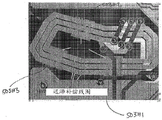
An exemplary implementation of the block diagram of fig. 5 is illustrated in fig. 5A. In this aspect, the printed circuit board 310 includes three sensing members 503H1, 503H2, 503H3 (each capable of providing two differential signals) for obtaining a position signal from a ferromagnetic track 202 (see, e.g., fig. 2C and 6A) having three scales 202S. In one aspect, the sensing members 503H1, 503H2, 503H3 (and other sensors described herein) may be immovably fixed to the circuit board. In other aspects, the sensing members (as well as other sensors described herein) may be movably mounted to the circuit board such that the sensing members are adjustable relative to their respective track 202 scale 202S. Referring to fig. 2C and 6A-6C, in one aspect, the scale 202S can represent a 3-scale vernier pattern including the main scale 202S1, the vernier scale 202S2, and the segment scale 202S3, but in other aspects the ferromagnetic track can include any suitable number of scales having any suitable positional relationship relative to one another. Here, each scale 2102S can include a respective equidistant pattern of ferromagnetic features 202SE (e.g., grooves, protrusions, etc.) (e.g., each scale pattern can have a respective pitch P1, P2, P3). For each scale 202S, there may be dedicated sensing members 503H1-503H3 configured to provide analog signal outputs that are substantially analog, e.g., sine and cosine waves. In one aspect, one or more of the sensing members 503H1-503H3 can be disposed at any suitable angle α 1, α 2 relative to another of the sensing members 503H1-503H3 and/or the respective track 202S 1-202S. In other aspects, the sensing members 503H1-503H3 can have any suitable positional relationship with respect to each other and/or the respective rails 202S1-202S 3. As can be appreciated, each scale period and number of ferromagnetic features 202SE allows for a track design that can be used to decode the absolute position of the track using any suitable cursor insertion method (see fig. 5, which illustrates one suitable absolute position decoding algorithm for a 3-scale track 202 as described herein).
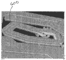
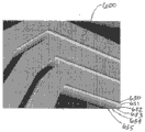
The one or more coils 600 may be integrally formed with the printed circuit board 310 as a one-piece unit (or otherwise mounted to or formed on the printed circuit board 310) in any suitable manner for hysteresis compensation as will be described below. It should be noted that the data sampling unit 502 and the decoding unit 507 may be formed as an integral device or module as shown in fig. 5A, while in other aspects the data acquisition unit 502 and the decoding unit 507 may be separate units. As can also be seen in fig. 5A, any suitable memory 505M may be connected to the control and synchronization unit 505.
In one aspect, the control and synchronization unit 505 may be configured to generate a sensor signal command to at least one sensor based on a sensor signal received from the at least one sensor, wherein the sensor signal command effects a change in at least one predetermined characteristic of the sensor signal. For example, the control and synchronization unit 505 may be configured to control the hysteresis in any suitable manner, such as by a hysteresis compensation mechanism or module 505C (e.g., one or more coils 600 and associated hardware and software for energizing the coils), as will be described below. In one aspect, the control and synchronization unit 505 may enable energizing the coils such that the respective sensing members 503H1, 503H2, 503H3 are driven to saturation. The control and synchronization unit 505 may schedule position data sampling times, e.g., using module 505E, such that position data is not sampled during times that compensate for hysteresis (e.g., position data is not sampled when one or more coils are energized). By compensating for hysteresis in the sensing means 503H, a consistent analog signal can be output by the sensing means 503H. In one aspect, one or more coils 600 may be provided on the printed circuit board 310 adjacent to the respective sensing members 503H1, 503H2, 503H3 as shown in fig. 7A-7D, which illustrate one or more coils 600 formed in one or more layers 630 and 635 on or in the printed circuit board 310. As an example of hysteresis compensation in accordance with aspects of the disclosed embodiments, the control and synchronization unit 505 may cause the application of a hysteresis compensation field in the one or more sensing members 503H by energizing the one or more coils 600 at any suitable time (fig. 5B, block 590). For example, in one aspect, the control and synchronization unit 505 may monitor the signal received from the sensor and may generate a hysteresis compensation field when a predetermined characteristic of the signal (e.g., noise, amplitude, signal distortion, etc.) is outside a predetermined range and/or exceeds a threshold. The control and synchronization unit 505 may wait a predetermined time after the hysteresis compensation field decays and then command the signal conditioning unit 501 to apply an appropriate (e.g., any appropriate) signal compensation to the resulting hysteresis compensation signal from one or more of the one or more sensing means 503H (fig. 5B, block 591). It should be noted that the position signals from the one or more sensing members 503H may not be valid during the time in which the one or more coils 600 are energized and the hysteresis compensation field is not decaying. Control and synchronization unit 505 may trigger or otherwise command data sampling unit 502 to convert the conditioned analog signal to digital data (fig. 5B, block 592), and command decoding unit 507 to collect digital data from data sampling unit 502 and translate this digital data into final corrected position data (fig. 5B, block 593). The control and synchronization unit 505 may instruct the propagation unit 504 to transmit the final corrected position data to any suitable controller (e.g., the controller 190) (fig. 5B, block 594) so that the controller 190 uses the final corrected position data to control the motion of the robot drive 200 and the one or more arms attached thereto.
Aspects of the disclosed embodiments may allow for a degree of customization that can be used to optimize the performance of any suitable position feedback system (e.g., the position feedback system described herein with respect to a semiconductor automation robot). In one aspect, the control and synchronization unit 505 and/or the data sampling unit 502 may be configured such that analog-to-digital conversion may be configured using oversampling (e.g., using module 505A) to allow improved noise immunity. As described above, data sampling and analog-to-digital conversion of the sensor signals may be performed to determine, for example, the position of the driver 200 (and thus the robotic arm) at a "static time" (e.g., using modules 505A and/or 505E), which, as described above, is a time within the loop at which noise events (e.g., noise events of hysteresis compensation, transients, etc.) are avoided. In another aspect, the control and synchronization unit 505 can include any suitable programming and/or algorithms stored in, for example, the memory 505M that allow absolute position decoding (e.g., using the module 505B) as needed, where the absolute position can be identified at power-up or at any other suitable time so that the incremental position can be properly aligned to the absolute position (which can be accomplished by different scales on the ferromagnetic track as described herein). The control and synchronization unit 505 may include any suitable programming and/or algorithms stored, for example, in memory 505M that allow for substantially automatic track alignment calibration (e.g., using module 505G) on-board (e.g., as determined locally by the processing capabilities of the sensors 203), wherein a common origin between different scales 202S of the ferromagnetic track 202 is identified (e.g., by comparing the signals of each scale), such that the tolerance of the position of the sensor member 503H can be relaxed relative to the ferromagnetic track 202 in the circuitry of the printed circuit board 310. As described above, the one or more coils 600 and the control and synchronization unit 505 may allow hysteresis compensation, which may be inherent to some sensing means, to be made as needed (as described above-e.g., using module 505C) at any suitable position of the ferromagnetic track (and thus the robotic driver/robotic arm) where position repeatability is desired. Control and synchronization unit 505 may include any suitable programming and/or algorithms stored, for example, in memory 505M that allow for substantially automatic amplitude, offset, and phase calibration (e.g., using module 505I) on-board that may allow for substantially instantaneous (where instantaneous refers to the operational cutoff time from event to system response) signal adjustment to compensate for drift due to, for example, mechanical jerk (or other state condition of the sensors, such as the rotational direction of track 202 and/or sensor hysteresis) and/or environmental condition effects (e.g., the temperature of at least one sensor). In another aspect, control and synchronization unit 505 may include any suitable programming and/or algorithms stored, for example, in memory 505M that allow for on-board temperature compensation (e.g., using module 505D). For example, the sensors 203 may include a temperature sensor 520 (fig. 5A) communicatively connected to the control and synchronization unit 505 for determining a temperature of one or more of: the printed circuit board 310, the sensing members 203H, 203H '', 503H1-503H3, the ferromagnetic track 202 (and/or the scale thereon), or any other suitable component of the sensor 203. Any suitable lookup table that relates, for example, sensor signals to temperature to provide signal adjustment compensation for temperature effects may be stored in any suitable memory (e.g., memory 505M). As can be seen in fig. 5A, the sensor may be provided with on-board analog-to-digital conversion for each scale 202S of the ferromagnetic track 202, which may allow for increased analog signal integrity and avoid the need for long interconnection cables between the position feedback sensor 203 and an external controller (e.g., controller 190). Control and synchronization unit 505 and/or propagation unit 504 may also be configured to provide multiple output protocols (e.g., using module 505H) to allow for substantially universal integration with different types of controllers. For example, the different communication protocols may be stored in any suitable memory of the sensor, such as memory 505M or memory stored in the propagation unit 504.
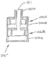
Referring now to fig. 8A and 8B, a portion of a sensor 203' in accordance with aspects of the disclosed embodiments is illustrated. The sensor 203' may be substantially similar to the sensors described above; however, in this aspect, the sensing means 803H (which may be substantially similar to the sensing means described above) may be disposed substantially within the sensor air gap 810 of the ferromagnetic loop means or flux loop (flux loop) 820. The ferromagnetic circuit member 820 may include: a magnetic source 300 (which may be a permanent magnet or one or more coils configured to generate a magnetic field as described above); a first leg 822 (which includes a sensor air gap 810) coupled to the magnetic source 300; a first extension member 823 communicatively connected to the first leg 822 such that the dividing wall 204 is disposed between the first extension member and the first leg (in other aspects, the first leg and the first extension member may be a one-piece member extending through the dividing wall 204 in any suitable manner); a second extension member 824 communicatively coupled with the first extension member 823 across the sensor track air gap 830; and a second leg 825 communicatively connected to the second extension member 824 such that the dividing wall 204 is disposed between the second extension member and the second leg (in other aspects, the first leg and the first extension member may be a one-piece member extending through the dividing wall 204 in any suitable manner). The second leg 825 is also coupled to the magnetic source 300. As can be seen in fig. 8A, the ferromagnetic circuit member 820 forms a magnetic circuit between the magnetic source 300 and the track 202 such that magnetic flux exits (for example) the north pole of the magnetic source 300, travels along the first leg 822, across the sensor air gap 810 where the sensor is located, across the non-ferromagnetic divider wall 204, continues along the first extension member 823 across the track air gap 830 (for example, through the track 202) and along the second extension member 823 to return through the divider wall 204 such that magnetic flux travels along the second leg 825 to (for example) the south pole of the magnetic source 300. The arrangement of the ferromagnetic circuit member 820 allows the sensing member 803H to detect changes in the reluctance of the sensor air gap 810 caused by changes in the distribution of the track 202 (e.g., when the track 202 moves relative to the extension members 823, 824) without having to be placed in the air gap between the track 202 and the magnetic source 300. The arrangement of the ferromagnetic circuit member 820 also allows the sensor electronics to be located in the external environment as described above. It should be noted that the dividing wall may be disposed between portions of the ferromagnetic circuit member in a manner substantially similar to that described in U.S. provisional patent entitled "SEALED ROBOT DRIVE" (attorney docket No. 390P014939-US (- # 1)) filed on 11/13/2013, previously incorporated by reference herein in its entirety.
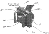
Referring now to fig. 9A-9C, a portion of a sensor 203 ″ in accordance with aspects of the disclosed embodiments is illustrated. The sensor 203 ″ may be substantially similar to the sensors described above; however, in this aspect, sensing component 803H (which can be substantially similar to the sensing components described above) can be disposed substantially within a sensor air gap 905 of a ferromagnetic bridge circuit 901 configured to simulate a wheatstone bridge. The ferromagnetic bridge circuit includes a first ferromagnetic circuit member 910 and a second ferromagnetic circuit member 911, which may be substantially similar to the ferromagnetic circuit member 820 described above, such that each of the first and second ferromagnetic circuit members 910, 911 has portions (e.g., separated by the dividing wall 204) that are located in an external environment and a sealed environment. Each of the ferromagnetic circuit members 910, 911 has two air gaps (e.g., one air gap disposed on either side of the partition wall 204). For example, ferromagnetic circuit member 910 includes air gap CR2 disposed in an external environment and CR1 disposed in a sealed environment, while ferromagnetic circuit member 911 includes air gap CR3 disposed in an external environment and air gap VR disposed in a sealed environment. It should be noted that the magnet 300 of each of the ferromagnetic circuit members 910, 911 is also disposed in the external environment in a manner generally similar to that described above with respect to fig. 8A and 8B. The air gaps CR1-CR3 may be constant reluctance air gaps. The air gap VR may be a variable reluctance air gap, where the variable reluctance is caused by one or more scales of the track 202 (which is located within the air gap VR). Bridge member BR communicatively connects ferromagnetic circuit members 910, 911 to each other and includes a sensor air gap 905 in which sensing member 803H is at least partially disposed. In operation, the ferromagnetic bridge circuit 901 is substantially balanced whenever the air gaps CR1-CR3, VR magnetoresistances are substantially equal to each other. With the ferromagnetic bridge circuit 901 balanced, the sensing member 803H does not detect a change in magnetic flux (or does not detect magnetic flux) across the sensor air gap 905. The reluctance balance is disturbed by the movement of the scale(s) of the track 202 across the air gap VR. For example, in the case of a rotating track 202 (or in other aspects, a linear track), as the track 202 moves, the magnetic flux changes as the sensor air gap 905 is crossed. Sensing member 803H senses or otherwise detects changes in magnetic flux due to, for example, the topology of track scale (S) 202S while utilizing a magnetic flux density that can be adjusted to operate within the linear range of sensing member 803H. It should be noted that by selecting the air gaps CR1-CR2, VR reluctance, the flux density in the ferromagnetic bridge circuit 901 can be adjusted.
As can be appreciated, in aspects of the disclosed embodiments shown in fig. 8A-9C, the portions of the ferromagnetic circuit that connect with the track 202 (S) scale 202S across the air gap 830, VR (e.g., the extension members 823, 824 and at least corresponding portions of the ferromagnetic circuit in fig. 9A-9C disposed in a sealed environment and including the track air gap VR) can include a pick-up (pick-up) feature PIC (fig. 9B) formed in or otherwise attached to the ferromagnetic material of the circuit. These pick-up features PIC may be disposed on opposite sides of the air gaps 830, VR and have a pitch substantially equal to the pitch P (fig. 3) of the respective scale 202S and have a size on the same order of magnitude as the ferromagnetic features 202SE of the scale 202S such that a local flux capable of sensing the track 202 distribution is established. These flux lines will sum and propagate to the sensing member 803H such that the result of the flux across the sensor air gaps 810, 905 is substantially uniform for any given position of the track 202. As can be seen in fig. 9B, when the pickup feature PIC is substantially aligned with the ferromagnetic feature 202SE of the scale 202S, substantially zero or no flux passes through the air gaps 830, VR. When the pickup feature PIC is not aligned with the ferromagnetic feature 202SE of the scale 202S, magnetic flux flows through the air gaps 830, VR such that movement of the ferromagnetic feature 202SE across the pickup feature PIC generates a sinusoidal wave (as shown in fig. 9D) that is detected by the sensing member 803H.
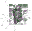
Referring now to fig. 10A-10C, a portion of a sensor 203' ″ in accordance with aspects of the disclosed embodiments is illustrated. The sensor 203' "may be substantially similar to the sensor 203"; however, in this aspect, bridge member BR ' includes flux concentrators FC1, FC2 configured to maximize magnetic flux flowing between ferromagnetic circuit member 910' and ferromagnetic circuit member 911' such that sensing member 803H is disposed across, or at least partially within, sensor air gap 905 defined by the flux concentrators FC1, FC 2. Also in this respect, ferromagnetic circuit members 910', 911' are illustrated without the reluctance-constant air gaps CR1-CR 3; in other respects, however, the ferromagnetic circuit members 910', 911' may include a constant reluctance air gap CR1-CR3 in a manner generally similar to that described above. As also seen in fig. 10A-10C, the partition walls may be disposed in the wall gaps WG in a manner generally similar to that described above with respect to fig. 8A-9C. In operation, each ferromagnetic circuit member 910', 911' has a corresponding magnetic flux Φ associated therewith1And phi2. In a manner generally similar to that described above, as the track 202 moves within the air gap VR, the ferromagnetic feature 202SE of the track 202 moves past the pick-up feature PIC of the ferromagnetic circuit member 911' such that the air gap between the ferromagnetic feature 202SE and the pick-up feature PIC changes, as shown in fig. 10B and 10C. As can be seen in fig. 10B, when the pickup feature PIC is substantially aligned with the ferromagnetic feature 202SE of the scale 202S, the effective air gap between the pickup feature PIC and the track 202 is at its maximum, such that the flux Φ1And phi2Substantially equal and substantially zero or no flux passes through the air gap VR and substantially no magnetic flux crosses the air gap 905. When the pickup feature PIC is not aligned with the ferromagnetic feature 202SE of the scale 202S, the effective air gap between the pickup feature PIC and the track 202 can be brought to its maximum value such that the reluctance across the air gap VR is higher than when the pickup feature PIC is substantially aligned with the ferromagnetic feature 202SE of the track 202, thereby causing a ferromagnetic returnFlux imbalance between road members 910', 911'. Due to flux imbalance between the ferromagnetic circuit members 910', 911', magnetic flux flows through the air gap VR, and as a result flux Φ3The flow (detected or otherwise sensed by sensing means 803H) crosses the sensor air gap 905. As can be appreciated, the movement of the ferromagnetic feature 202SE across the pickup feature PIC causes a flux Φ3Varying between a maximum and a minimum such that the flux phi3Simulating a sine wave detected by sensing member 803H (e.g., as shown in fig. 9D).
It should be noted that the flux Φ can be adjusted in any suitable manner1And phi2To balance the flux of the ferromagnetic circuit members 910', 911, such as by adjusting the size of the wall gap WG (e.g., DC offset) and/or the size of the sensor air gap 905 (e.g., signal amplitude) of at least one of the ferromagnetic circuit members 910', 911', as shown in fig. 10D. As can be appreciated, the air gap 905 across the sensing member 803H may determine the amount of maximum flux detected during the moment of misalignment between the pickup feature PIC and the ferromagnetic feature 202 SE. It is also possible to induce a DC component of the magnetic flux by causing a constant imbalance between the ferromagnetic circuit members 910', 911' (by varying the wall gap WG across the dividing wall of only one of the ferromagnetic circuit members 910', 911').
As can be appreciated, as shown in fig. 8A-9C and 10A-10D, more than one sensor can be integrated with or otherwise mounted to the printed circuit board 310 in a manner substantially similar to that described above. As can be seen in fig. 11, a sensor configuration is illustrated that is substantially similar to the sensor configuration described above with respect to fig. 5A, 6A-6C, wherein the sensor track 202 includes a main scale 202S1 (e.g., can produce a sine wave), a vernier scale 202S2 (e.g., can produce any suitable reference waveform), and a segment scale 202S3 (e.g., can produce a cosine wave), wherein the main scale and the segment scale are measured with reference to the vernier scale. Corresponding ferromagnetic circuit members 1101-1103 (which may be substantially similar to one or more of the ferromagnetic circuit members described above with respect to fig. 8A-9C and 10A-10D) are integrated with or otherwise mounted to the printed circuit board 310 for connection with a respective one of the scales 202S1-202S3 such that the sensing members 803H are disposed adjacent to the respective one or more coils 600 (fig. 5A and 7A-7D) to achieve hysteresis compensation as described above. The signals from each of the sensing members of ferromagnetic circuit members 1101-1103 can be processed as described above to determine the position of track 202 and thus robotic drive 200 and/or arm(s) 208 connected to the robotic drive.
As can be appreciated, the aspects of the disclosed embodiments described above provide a position sensor that is capable of true absolute position measurement/feedback, and for which no electronic components, cables, or magnets are located in a sealed environment. Thus, there is no need to seal the through-hole in the connector through the partition wall 204. As can also be appreciated, aspects of the position sensors described herein provide for operation of the position sensor in harsh environments (e.g., corrosive, extreme temperatures, high pressure, high vacuum, liquid media, etc.). Aspects of the position sensor described herein also provide for operation of the position sensor in the presence of contaminants (e.g., due to magnetic principles employed by the position sensor) that might otherwise prevent reading of the scale 202S of the track 202 (e.g., in the case of an optical sensor).
In accordance with one or more aspects of the disclosed embodiments, a delivery apparatus comprises: a housing; a driver mounted to the housing; at least one transport arm connected to a drive, the drive comprising: at least one rotor having at least one salient pole of magnetically permeable material and disposed in an isolated environment; at least one stator having at least one salient pole and a corresponding coil unit and disposed outside of an isolated environment, wherein the at least one salient pole of the at least one stator and the at least one salient pole of the rotor form a closed magnetic flux loop between the at least one rotor and the at least one stator; and at least one sealed partition configured to isolate the isolation environment; and at least one sensor, the at least one sensor comprising: a magnetic sensor member connected to the housing; at least one sensor track connected to the at least one rotor, wherein the at least one seal partition is disposed between and separates the magnetic sensor member and the at least one sensor track such that the at least one sensor track is disposed in an isolated environment and the magnetic sensor member is disposed outside of the isolated environment.
In accordance with one or more aspects of the disclosed embodiment, at least a portion of the at least one seal partition is integrated into the magnetic sensor member.
In accordance with one or more aspects of the disclosed embodiment, the at least one sensor includes at least one ferromagnetic flux loop having a sensor air gap, wherein the magnetic sensor member is connected with the at least one ferromagnetic flux loop.
In accordance with one or more aspects of the disclosed embodiment, the magnetic sensor member is configured to detect a change in reluctance of the sensor air gap.
In accordance with one or more aspects of the disclosed embodiments, the at least one ferromagnetic flux loop includes a first ferromagnetic flux loop and a second ferromagnetic flux loop having a sensor bridge member therebetween, wherein the sensor air gap is located in the sensor bridge member, one of the first ferromagnetic flux loop and the second ferromagnetic flux loop having a track air gap in which at least a portion of the at least one sensor track is disposed.
In accordance with one or more aspects of the disclosed embodiment, the at least one ferromagnetic flux loop emulates a wheatstone bridge.
In accordance with one or more aspects of the disclosed embodiment, each of the at least one ferromagnetic flux loop comprises: a track interface portion disposed in the isolated environment; and a sensor component interface portion disposed outside of the isolated environment, the track interface portion and the sensor component interface portion separated by the at least one sealed partition.
In accordance with one or more aspects of the disclosed embodiment, the at least one ferromagnetic flux loop comprises a flux concentrator element disposed in the sensor air gap.
In accordance with one or more aspects of the disclosed embodiments, the at least one ferromagnetic flux loop includes a track air gap in which at least a portion of the at least one sensor track is disposed.
In accordance with one or more aspects of the disclosed embodiment, the at least one sensor includes a substantially featureless track interface.
In accordance with one or more aspects of the disclosed embodiment, the at least one sensor track comprises: a first track having a first pitch; and at least a second track having a respective pitch different from at least the first pitch, and the at least one sensor comprises: a first sensor corresponding to the first track; and at least a second sensor corresponding to a respective one of the at least second tracks.
In accordance with one or more aspects of the disclosed embodiment, the magnetic sensor member includes a differential sensor having sensor elements arranged to substantially match a pitch of the at least one sensor track such that differential sine and cosine output signals are obtained from the magnetic sensor member.
In accordance with one or more aspects of the disclosed embodiments, the sensor elements form a wheatstone bridge.
In accordance with one or more aspects of the disclosed embodiment, the sensor elements are disposed on a common printed circuit board of the magnetic sensor member.
In accordance with one or more aspects of the disclosed embodiment, the at least one sensor is substantially directly connected with the at least one sensor track through the at least one seal partition.
In accordance with one or more aspects of the disclosed embodiments, a delivery apparatus comprises: a housing; a driver mounted to the housing; at least one transport arm connected to a drive, the drive comprising: at least one rotor having at least one salient pole of magnetically permeable material and disposed in an isolated environment; at least one stator having at least one salient pole and a corresponding coil unit and disposed outside of an isolated environment, wherein the at least one salient pole of the at least one stator and the at least one salient pole of the rotor form a closed magnetic flux loop between the at least one rotor and the at least one stator; and at least one sealed partition configured to isolate the isolation environment; and at least one sensor, the at least one sensor comprising: a magnetic sensor member connected to the housing; at least one sensor track connected to the at least one rotor, wherein the at least one seal partition is disposed between and separates the magnetic sensor member and the at least one sensor track such that the at least one sensor track is disposed in an isolated environment and the magnetic sensor member is disposed outside of the isolated environment; and a sensor controller configured to generate a sensor signal command to the at least one sensor based on a sensor signal received from the at least one sensor, wherein the sensor signal command effects a change in at least a predetermined characteristic of the sensor signal.
In accordance with one or more aspects of the disclosed embodiment, at least a portion of the at least one seal partition is integrated into the magnetic sensor member.
In accordance with one or more aspects of the disclosed embodiment, the at least one sensor includes at least one ferromagnetic flux loop having a sensor air gap, wherein the magnetic sensor member is connected with the ferromagnetic flux loop.
In accordance with one or more aspects of the disclosed embodiment, the magnetic sensor member is configured to detect a change in reluctance of the sensor air gap.
In accordance with one or more aspects of the disclosed embodiments, the at least one ferromagnetic flux loop includes a first ferromagnetic flux loop and a second ferromagnetic flux loop having a sensor bridge member therebetween, wherein the sensor air gap is located in the sensor bridge member, one of the first ferromagnetic flux loop and the second ferromagnetic flux loop having a track air gap in which at least a portion of the at least one sensor track is disposed.
In accordance with one or more aspects of the disclosed embodiment, the at least one ferromagnetic flux loop emulates a wheatstone bridge.
In accordance with one or more aspects of the disclosed embodiment, each of the at least one ferromagnetic flux loop comprises: a track interface portion disposed in the isolated environment; and a sensor component interface portion disposed outside of the isolated environment, the track interface portion and the sensor component interface portion separated by the at least one sealed partition.
In accordance with one or more aspects of the disclosed embodiments, wherein the at least one ferromagnetic flux loop comprises a flux concentrator element disposed in the sensor air gap.
In accordance with one or more aspects of the disclosed embodiments, the at least one ferromagnetic flux loop includes a track air gap in which at least a portion of the at least one sensor track is disposed.
In accordance with one or more aspects of the disclosed embodiment, the at least one sensor includes a substantially featureless track interface.
In accordance with one or more aspects of the disclosed embodiment, the at least one sensor track comprises: a first track having a first pitch; and at least a second track having a respective pitch different from at least the first pitch, and the at least one sensor comprises: a first sensor corresponding to the first track; and at least a second sensor corresponding to a respective one of the at least second tracks.
In accordance with one or more aspects of the disclosed embodiment, the magnetic sensor member includes a differential sensor having sensor elements arranged to substantially match a pitch of the at least one sensor track such that differential sine and cosine output signals are obtained from the magnetic sensor member.
In accordance with one or more aspects of the disclosed embodiments, the sensor elements form a wheatstone bridge.
In accordance with one or more aspects of the disclosed embodiment, the sensor elements are disposed on a common printed circuit board of the magnetic sensor member.
In accordance with one or more aspects of the disclosed embodiment, the at least one sensor is substantially directly connected with the at least one sensor track through the at least one seal partition.
In accordance with one or more aspects of the disclosed embodiments, a delivery apparatus comprises: a housing; a driver mounted to the housing; at least one transport arm connected to a drive, the drive comprising: at least one rotor having at least one salient pole of magnetically permeable material and disposed in an isolated environment; at least one stator having at least one salient pole and a corresponding coil unit and disposed outside of an isolated environment, wherein the at least one salient pole of the at least one stator and the at least one salient pole of the rotor form a closed magnetic flux loop between the at least one rotor and the at least one stator; and at least one sealed partition configured to isolate the isolation environment; and at least one sensor, the at least one sensor comprising: a magnetic sensor member connected to the housing; at least one sensor track connected to the at least one rotor, wherein the at least one seal partition is disposed between and separates the magnetic sensor member and the at least one sensor track such that the at least one sensor track is disposed in an isolated environment and the magnetic sensor member is disposed outside of the isolated environment; a sensor controller communicatively connected to the at least one sensor, the sensor controller configured to provide sensor signal commands; and a motion controller communicatively connected to the at least one sensor and the sensor controller and configured to receive a sensor signal from the at least one sensor, wherein the sensor controller is configured to control a change in at least a predetermined characteristic of the sensor signal in response to a communication from the motion controller.
In accordance with one or more aspects of the disclosed embodiment, at least a portion of the at least one seal partition is integrated into the magnetic sensor member.
In accordance with one or more aspects of the disclosed embodiment, the at least one sensor includes at least one ferromagnetic flux loop having a sensor air gap at which the magnetic sensor member is connected with the ferromagnetic flux loop.
In accordance with one or more aspects of the disclosed embodiment, the magnetic sensor member is configured to detect a change in reluctance of the sensor air gap.
In accordance with one or more aspects of the disclosed embodiments, the at least one ferromagnetic flux loop includes a first ferromagnetic flux loop and a second ferromagnetic flux loop having a sensor bridge member therebetween, wherein the sensor air gap is located in the sensor bridge member, one of the first ferromagnetic flux loop and the second ferromagnetic flux loop having a track air gap in which at least a portion of the at least one sensor track is disposed.
In accordance with one or more aspects of the disclosed embodiment, the at least one ferromagnetic flux loop emulates a wheatstone bridge.
In accordance with one or more aspects of the disclosed embodiment, each of the at least one ferromagnetic flux loop comprises: a track interface portion disposed in the isolated environment; and a sensor component interface portion disposed outside of the isolated environment, the track interface portion and the sensor component interface portion separated by the at least one sealed partition.
In accordance with one or more aspects of the disclosed embodiment, the at least one ferromagnetic flux loop comprises a flux concentrator element disposed in the sensor air gap.
In accordance with one or more aspects of the disclosed embodiments, the at least one ferromagnetic flux loop includes a track air gap in which at least a portion of the at least one sensor track is disposed.
In accordance with one or more aspects of the disclosed embodiment, the at least one sensor includes a substantially featureless track interface.
In accordance with one or more aspects of the disclosed embodiment, the at least one sensor track comprises: a first track having a first pitch; and at least a second track having a respective pitch different from at least the first pitch, and the at least one sensor comprises: a first sensor corresponding to the first track; and at least a second sensor corresponding to a respective one of the at least second tracks.
In accordance with one or more aspects of the disclosed embodiment, the magnetic sensor member includes a differential sensor having sensor elements arranged to substantially match a pitch of the at least one sensor track such that differential sine and cosine output signals are obtained from the magnetic sensor member.
In accordance with one or more aspects of the disclosed embodiments, the sensor elements form a wheatstone bridge.
In accordance with one or more aspects of the disclosed embodiment, the sensor elements are disposed on a common printed circuit board of the magnetic sensor member.
In accordance with one or more aspects of the disclosed embodiment, the at least one sensor is substantially directly connected with the at least one sensor track through the at least one seal partition.
In accordance with one or more aspects of the disclosed embodiments, a delivery apparatus comprises: a housing; a driver mounted to the housing; at least one transport arm connected to a drive, the drive comprising: at least one rotor having at least one salient pole of magnetically permeable material and disposed in an isolated environment; at least one stator having at least one salient pole and a corresponding coil unit and disposed outside of an isolated environment, wherein the at least one salient pole of the at least one stator and the at least one salient pole of the rotor form a closed magnetic flux loop between the at least one rotor and the at least one stator; and at least one sealed partition configured to isolate the isolation environment; and at least one sensor, the at least one sensor comprising: a magnetic sensor member connected to the housing; at least one sensor track connected to the at least one rotor, wherein the at least one seal partition is disposed between and separates the magnetic sensor member and the at least one sensor track such that the at least one sensor track is disposed in an isolated environment and the magnetic sensor member is disposed outside of the isolated environment; and a sensor controller configured to perform immediate sensor signal tuning in response to a change in at least one of an environmental condition of the at least one sensor or a state condition of the at least one sensor.
In accordance with one or more aspects of the disclosed embodiment, the environmental condition of the at least one sensor is a temperature of the at least one sensor.
In accordance with one or more aspects of the disclosed embodiment, the state condition of the at least one sensor is at least one of a rotational direction of the at least one sensor track or a sensor hysteresis.
In accordance with one or more aspects of the disclosed embodiment, at least a portion of the at least one seal partition is integrated into the magnetic sensor member.
In accordance with one or more aspects of the disclosed embodiment, the at least one sensor includes at least one ferromagnetic flux loop having a sensor air gap where the magnetic sensor member is connected with the at least one ferromagnetic flux loop.
In accordance with one or more aspects of the disclosed embodiment, the magnetic member is configured to detect a change in reluctance of the sensor air gap.
In accordance with one or more aspects of the disclosed embodiments, the at least one ferromagnetic flux loop includes a first ferromagnetic flux loop and a second ferromagnetic flux loop having a sensor bridge member therebetween, wherein the sensor air gap is located in the sensor bridge member, one of the first ferromagnetic flux loop and the second ferromagnetic flux loop having a track air gap in which at least a portion of the at least one sensor track is disposed.
In accordance with one or more aspects of the disclosed embodiment, the at least one ferromagnetic flux loop emulates a wheatstone bridge.
In accordance with one or more aspects of the disclosed embodiment, each of the at least one ferromagnetic flux loop comprises: a track interface portion disposed in the isolated environment; and a sensor component interface portion disposed outside of the isolated environment, the track interface portion and the sensor component interface portion separated by the at least one sealed partition.
In accordance with one or more aspects of the disclosed embodiment, the at least one ferromagnetic flux loop comprises a flux concentrator element disposed in the sensor air gap.
In accordance with one or more aspects of the disclosed embodiments, the at least one ferromagnetic flux loop includes a track air gap in which at least a portion of the at least one sensor track is disposed.
In accordance with one or more aspects of the disclosed embodiment, the at least one sensor includes a substantially featureless track interface.
In accordance with one or more aspects of the disclosed embodiment, the at least one sensor track comprises: a first track having a first pitch; and at least a second track having a respective pitch different from at least the first pitch, and the at least one sensor comprises: a first sensor corresponding to the first track; and at least a second sensor corresponding to a respective one of the at least second tracks.
In accordance with one or more aspects of the disclosed embodiment, the magnetic sensor member includes a differential sensor having sensor elements arranged to substantially match a pitch of the at least one sensor track such that differential sine and cosine output signals are obtained from the magnetic sensor member.
In accordance with one or more aspects of the disclosed embodiments, the sensor elements form a wheatstone bridge.
In accordance with one or more aspects of the disclosed embodiment, the sensor elements are disposed on a common printed circuit board of the magnetic sensor member.
In accordance with one or more aspects of the disclosed embodiment, the at least one sensor is substantially directly connected with the at least one sensor track through the at least one seal partition.
In accordance with one or more aspects of the disclosed embodiments, a delivery apparatus comprises: a frame; a drive section connected to the frame and having at least one drive shaft; a transport arm movably mounted to the drive section and driven by the at least one drive shaft; and a position feedback device comprising: at least one track mounted to a respective one of the at least one drive shaft, each of the at least one track having at least one scale disposed thereon; and at least one read head corresponding to a respective track, the at least one read head comprising: at least one sensor mounted to a common support member, the at least one sensor configured to sense a respective scale on the respective track; and at least one excitation coil integrally formed with the support member.
In accordance with one or more aspects of the disclosed embodiment, the at least one excitation coil is configured to generate an excitation pulse through the respective sensor to substantially eliminate sensor hysteresis.
In accordance with one or more aspects of the disclosed embodiment, the transport apparatus further includes a controller connected to the at least one read head, the controller configured to sample the trajectory data from the at least one sensor such that sampling occurs a predetermined time after the excitation pulse is generated through the respective sensor.
In accordance with one or more aspects of the disclosed embodiments, the excitation pulse saturates the sensor.
In accordance with one or more aspects of the disclosed embodiments, the at least one read head and the respective track are separated from each other by a dividing wall such that the respective track is disposed in a first environment and the at least one read head is disposed in a second environment different from the first environment.
In accordance with one or more aspects of the disclosed embodiment, the first environment is a vacuum environment and the second environment is an atmospheric environment.
In accordance with one or more aspects of the disclosed embodiment, the at least one sensor includes a substantially featureless (featureless) track interface.
In accordance with one or more aspects of the disclosed embodiment, the at least one scale comprises: a first scale having a first pitch; and at least a second scale having a respective pitch different from at least the first pitch, and the at least one sensor comprises: a first sensor corresponding to the first scale; and at least a second sensor corresponding to a respective one of the at least second scales.
In accordance with one or more aspects of the disclosed embodiment, the first sensor and the at least second sensor are non-movably secured to the support member.
In accordance with one or more aspects of the disclosed embodiments, the at least one sensor comprises a giant magnetoresistive sensor or any suitable magnetic sensor.
In accordance with one or more aspects of the disclosed embodiments, a variable reluctance motor assembly comprises: a housing having a drum structure; a stator mounted within the drum structure; a rotor installed in the drum structure and connected to the stator; a sensor track connected to the rotor; and a giant magnetoresistive sensor mounted to the casing, wherein the casing comprises a common reference forming a stator interface surface configured to support the stator and position the stator and the rotor relative to each other for achieving a predetermined gap between the stator and the rotor, and configured to support the giant magnetoresistive sensor in a predetermined position relative to the common reference so as to achieve a predetermined gap between the giant magnetoresistive sensor and the sensor track, wherein the stator, the rotor, the giant magnetoresistive sensor, and the sensor track are positioned relative to the common reference and suspended from the common reference.
In accordance with one or more aspects of the disclosed embodiment, the variable reluctance motor assembly further comprises a dividing wall 2403 supported by the stator such that the dividing wall is located in a predetermined position relative to the common reference plane and the rotor.
In accordance with one or more aspects of the disclosed embodiments, the housing is a unitary member that forms a roller structure and has a plurality of slots formed therein for one or more of the sensors, the control board, and the drive connectors.
In accordance with one or more aspects of the disclosed embodiments, the housing is a unitary assembly formed from two or more ring members connected to one another to form a drum structure.
In accordance with one or more aspects of the disclosed embodiments, a variable reluctance motor housing includes an outer surface, an inner surface, wherein the outer surface and the inner surface form a drum structure, the inner surface including a common reference plane that forms both: a stator interface surface configured to support the stator and position the stator and rotor relative to each other within the housing to achieve a predetermined clearance between the stator and rotor; and a sensor interface surface configured to support the giant magnetoresistive sensor relative to a sensor track connected to the rotor and to achieve a predetermined gap between the giant magnetoresistive sensor and the sensor track, wherein the sensor interface is positioned relative to the common reference plane such that the stator, the rotor, and the giant magnetoresistive sensor are positioned from and supported by the common reference plane.
In accordance with one or more aspects of the disclosed embodiment, the inner surface includes a rotor interface surface that is positioned relative to the common reference plane such that the common reference plane is positioned from the common reference plane and supports the stator and rotor therefrom.
In accordance with one or more aspects of the disclosed embodiments, the sensor interface surface is formed as a groove within the drum structure.
In accordance with one or more aspects of the disclosed embodiment, the slot is configured to receive a sensor and a motor control board.
In accordance with one or more aspects of the disclosed embodiments, the drum structure is a unitary member having a plurality of slots formed therein for one or more of the sensors, control board and drive connectors.
In accordance with one or more aspects of the disclosed embodiments, the drum structure is a unitary assembly formed from two or more ring members connected to one another.
It should be understood that the foregoing description is only illustrative of aspects of the disclosed embodiments. Various alternatives and modifications can be devised by those skilled in the art without departing from aspects of the disclosed embodiments. Accordingly, the aspects of the disclosed embodiments are intended to embrace all such alternatives, modifications and variances that fall within the scope of the appended claims. Furthermore, the mere fact that different features are recited in mutually different dependent or independent claims does not indicate that a combination of these features cannot be used to advantage, and such a combination is still within the scope of the aspects of the present invention.