CN107094370B - 0-1 balance management for solid state hard disk controller - Google Patents
0-1 balance management for solid state hard disk controller Download PDFInfo
- Publication number
- CN107094370B CN107094370B CN201380023414.XA CN201380023414A CN107094370B CN 107094370 B CN107094370 B CN 107094370B CN 201380023414 A CN201380023414 A CN 201380023414A CN 107094370 B CN107094370 B CN 107094370B
- Authority
- CN
- China
- Prior art keywords
- read
- volatile memory
- threshold voltage
- data
- bits
- Prior art date
- Legal status (The legal status is an assumption and is not a legal conclusion. Google has not performed a legal analysis and makes no representation as to the accuracy of the status listed.)
- Expired - Fee Related
Links
Images


Classifications
-
- G—PHYSICS
- G06—COMPUTING; CALCULATING OR COUNTING
- G06F—ELECTRIC DIGITAL DATA PROCESSING
- G06F11/00—Error detection; Error correction; Monitoring
- G06F11/07—Responding to the occurrence of a fault, e.g. fault tolerance
- G06F11/08—Error detection or correction by redundancy in data representation, e.g. by using checking codes
- G06F11/10—Adding special bits or symbols to the coded information, e.g. parity check, casting out 9's or 11's
- G06F11/1008—Adding special bits or symbols to the coded information, e.g. parity check, casting out 9's or 11's in individual solid state devices
- G06F11/1068—Adding special bits or symbols to the coded information, e.g. parity check, casting out 9's or 11's in individual solid state devices in sector programmable memories, e.g. flash disk
-
- H—ELECTRICITY
- H03—ELECTRONIC CIRCUITRY
- H03M—CODING; DECODING; CODE CONVERSION IN GENERAL
- H03M13/00—Coding, decoding or code conversion, for error detection or error correction; Coding theory basic assumptions; Coding bounds; Error probability evaluation methods; Channel models; Simulation or testing of codes
- H03M13/03—Error detection or forward error correction by redundancy in data representation, i.e. code words containing more digits than the source words
- H03M13/05—Error detection or forward error correction by redundancy in data representation, i.e. code words containing more digits than the source words using block codes, i.e. a predetermined number of check bits joined to a predetermined number of information bits
- H03M13/11—Error detection or forward error correction by redundancy in data representation, i.e. code words containing more digits than the source words using block codes, i.e. a predetermined number of check bits joined to a predetermined number of information bits using multiple parity bits
- H03M13/1102—Codes on graphs and decoding on graphs, e.g. low-density parity check [LDPC] codes
-
- G—PHYSICS
- G11—INFORMATION STORAGE
- G11C—STATIC STORES
- G11C16/00—Erasable programmable read-only memories
- G11C16/02—Erasable programmable read-only memories electrically programmable
- G11C16/06—Auxiliary circuits, e.g. for writing into memory
-
- G—PHYSICS
- G06—COMPUTING; CALCULATING OR COUNTING
- G06F—ELECTRIC DIGITAL DATA PROCESSING
- G06F11/00—Error detection; Error correction; Monitoring
- G06F11/07—Responding to the occurrence of a fault, e.g. fault tolerance
- G06F11/08—Error detection or correction by redundancy in data representation, e.g. by using checking codes
- G06F11/10—Adding special bits or symbols to the coded information, e.g. parity check, casting out 9's or 11's
- G06F11/1008—Adding special bits or symbols to the coded information, e.g. parity check, casting out 9's or 11's in individual solid state devices
- G06F11/1012—Adding special bits or symbols to the coded information, e.g. parity check, casting out 9's or 11's in individual solid state devices using codes or arrangements adapted for a specific type of error
-
- G—PHYSICS
- G06—COMPUTING; CALCULATING OR COUNTING
- G06F—ELECTRIC DIGITAL DATA PROCESSING
- G06F11/00—Error detection; Error correction; Monitoring
- G06F11/07—Responding to the occurrence of a fault, e.g. fault tolerance
- G06F11/08—Error detection or correction by redundancy in data representation, e.g. by using checking codes
- G06F11/10—Adding special bits or symbols to the coded information, e.g. parity check, casting out 9's or 11's
- G06F11/1008—Adding special bits or symbols to the coded information, e.g. parity check, casting out 9's or 11's in individual solid state devices
- G06F11/1048—Adding special bits or symbols to the coded information, e.g. parity check, casting out 9's or 11's in individual solid state devices using arrangements adapted for a specific error detection or correction feature
-
- G—PHYSICS
- G06—COMPUTING; CALCULATING OR COUNTING
- G06F—ELECTRIC DIGITAL DATA PROCESSING
- G06F11/00—Error detection; Error correction; Monitoring
- G06F11/07—Responding to the occurrence of a fault, e.g. fault tolerance
- G06F11/08—Error detection or correction by redundancy in data representation, e.g. by using checking codes
- G06F11/10—Adding special bits or symbols to the coded information, e.g. parity check, casting out 9's or 11's
- G06F11/1008—Adding special bits or symbols to the coded information, e.g. parity check, casting out 9's or 11's in individual solid state devices
- G06F11/1072—Adding special bits or symbols to the coded information, e.g. parity check, casting out 9's or 11's in individual solid state devices in multilevel memories
-
- G—PHYSICS
- G06—COMPUTING; CALCULATING OR COUNTING
- G06F—ELECTRIC DIGITAL DATA PROCESSING
- G06F3/00—Input arrangements for transferring data to be processed into a form capable of being handled by the computer; Output arrangements for transferring data from processing unit to output unit, e.g. interface arrangements
- G06F3/06—Digital input from, or digital output to, record carriers, e.g. RAID, emulated record carriers or networked record carriers
- G06F3/0601—Interfaces specially adapted for storage systems
- G06F3/0602—Interfaces specially adapted for storage systems specifically adapted to achieve a particular effect
- G06F3/061—Improving I/O performance
-
- G—PHYSICS
- G06—COMPUTING; CALCULATING OR COUNTING
- G06F—ELECTRIC DIGITAL DATA PROCESSING
- G06F3/00—Input arrangements for transferring data to be processed into a form capable of being handled by the computer; Output arrangements for transferring data from processing unit to output unit, e.g. interface arrangements
- G06F3/06—Digital input from, or digital output to, record carriers, e.g. RAID, emulated record carriers or networked record carriers
- G06F3/0601—Interfaces specially adapted for storage systems
- G06F3/0602—Interfaces specially adapted for storage systems specifically adapted to achieve a particular effect
- G06F3/0614—Improving the reliability of storage systems
- G06F3/0619—Improving the reliability of storage systems in relation to data integrity, e.g. data losses, bit errors
-
- G—PHYSICS
- G06—COMPUTING; CALCULATING OR COUNTING
- G06F—ELECTRIC DIGITAL DATA PROCESSING
- G06F3/00—Input arrangements for transferring data to be processed into a form capable of being handled by the computer; Output arrangements for transferring data from processing unit to output unit, e.g. interface arrangements
- G06F3/06—Digital input from, or digital output to, record carriers, e.g. RAID, emulated record carriers or networked record carriers
- G06F3/0601—Interfaces specially adapted for storage systems
- G06F3/0628—Interfaces specially adapted for storage systems making use of a particular technique
- G06F3/0655—Vertical data movement, i.e. input-output transfer; data movement between one or more hosts and one or more storage devices
- G06F3/0658—Controller construction arrangements
-
- G—PHYSICS
- G06—COMPUTING; CALCULATING OR COUNTING
- G06F—ELECTRIC DIGITAL DATA PROCESSING
- G06F3/00—Input arrangements for transferring data to be processed into a form capable of being handled by the computer; Output arrangements for transferring data from processing unit to output unit, e.g. interface arrangements
- G06F3/06—Digital input from, or digital output to, record carriers, e.g. RAID, emulated record carriers or networked record carriers
- G06F3/0601—Interfaces specially adapted for storage systems
- G06F3/0668—Interfaces specially adapted for storage systems adopting a particular infrastructure
- G06F3/0671—In-line storage system
- G06F3/0673—Single storage device
- G06F3/0674—Disk device
- G06F3/0676—Magnetic disk device
-
- G—PHYSICS
- G06—COMPUTING; CALCULATING OR COUNTING
- G06F—ELECTRIC DIGITAL DATA PROCESSING
- G06F3/00—Input arrangements for transferring data to be processed into a form capable of being handled by the computer; Output arrangements for transferring data from processing unit to output unit, e.g. interface arrangements
- G06F3/06—Digital input from, or digital output to, record carriers, e.g. RAID, emulated record carriers or networked record carriers
- G06F3/0601—Interfaces specially adapted for storage systems
- G06F3/0668—Interfaces specially adapted for storage systems adopting a particular infrastructure
- G06F3/0671—In-line storage system
- G06F3/0673—Single storage device
- G06F3/0679—Non-volatile semiconductor memory device, e.g. flash memory, one time programmable memory [OTP]
-
- G—PHYSICS
- G11—INFORMATION STORAGE
- G11C—STATIC STORES
- G11C16/00—Erasable programmable read-only memories
- G11C16/02—Erasable programmable read-only memories electrically programmable
- G11C16/06—Auxiliary circuits, e.g. for writing into memory
- G11C16/34—Determination of programming status, e.g. threshold voltage, overprogramming or underprogramming, retention
-
- G—PHYSICS
- G11—INFORMATION STORAGE
- G11C—STATIC STORES
- G11C29/00—Checking stores for correct operation ; Subsequent repair; Testing stores during standby or offline operation
- G11C29/52—Protection of memory contents; Detection of errors in memory contents
-
- H—ELECTRICITY
- H03—ELECTRONIC CIRCUITRY
- H03M—CODING; DECODING; CODE CONVERSION IN GENERAL
- H03M13/00—Coding, decoding or code conversion, for error detection or error correction; Coding theory basic assumptions; Coding bounds; Error probability evaluation methods; Channel models; Simulation or testing of codes
- H03M13/03—Error detection or forward error correction by redundancy in data representation, i.e. code words containing more digits than the source words
- H03M13/05—Error detection or forward error correction by redundancy in data representation, i.e. code words containing more digits than the source words using block codes, i.e. a predetermined number of check bits joined to a predetermined number of information bits
- H03M13/13—Linear codes
- H03M13/15—Cyclic codes, i.e. cyclic shifts of codewords produce other codewords, e.g. codes defined by a generator polynomial, Bose-Chaudhuri-Hocquenghem [BCH] codes
- H03M13/151—Cyclic codes, i.e. cyclic shifts of codewords produce other codewords, e.g. codes defined by a generator polynomial, Bose-Chaudhuri-Hocquenghem [BCH] codes using error location or error correction polynomials
- H03M13/1515—Reed-Solomon codes
-
- G—PHYSICS
- G06—COMPUTING; CALCULATING OR COUNTING
- G06F—ELECTRIC DIGITAL DATA PROCESSING
- G06F2206/00—Indexing scheme related to dedicated interfaces for computers
- G06F2206/10—Indexing scheme related to storage interfaces for computers, indexing schema related to group G06F3/06
- G06F2206/1014—One time programmable [OTP] memory, e.g. PROM, WORM
-
- H—ELECTRICITY
- H03—ELECTRONIC CIRCUITRY
- H03M—CODING; DECODING; CODE CONVERSION IN GENERAL
- H03M13/00—Coding, decoding or code conversion, for error detection or error correction; Coding theory basic assumptions; Coding bounds; Error probability evaluation methods; Channel models; Simulation or testing of codes
- H03M13/03—Error detection or forward error correction by redundancy in data representation, i.e. code words containing more digits than the source words
- H03M13/05—Error detection or forward error correction by redundancy in data representation, i.e. code words containing more digits than the source words using block codes, i.e. a predetermined number of check bits joined to a predetermined number of information bits
- H03M13/09—Error detection only, e.g. using cyclic redundancy check [CRC] codes or single parity bit
-
- H—ELECTRICITY
- H03—ELECTRONIC CIRCUITRY
- H03M—CODING; DECODING; CODE CONVERSION IN GENERAL
- H03M13/00—Coding, decoding or code conversion, for error detection or error correction; Coding theory basic assumptions; Coding bounds; Error probability evaluation methods; Channel models; Simulation or testing of codes
- H03M13/03—Error detection or forward error correction by redundancy in data representation, i.e. code words containing more digits than the source words
- H03M13/05—Error detection or forward error correction by redundancy in data representation, i.e. code words containing more digits than the source words using block codes, i.e. a predetermined number of check bits joined to a predetermined number of information bits
- H03M13/13—Linear codes
- H03M13/15—Cyclic codes, i.e. cyclic shifts of codewords produce other codewords, e.g. codes defined by a generator polynomial, Bose-Chaudhuri-Hocquenghem [BCH] codes
- H03M13/151—Cyclic codes, i.e. cyclic shifts of codewords produce other codewords, e.g. codes defined by a generator polynomial, Bose-Chaudhuri-Hocquenghem [BCH] codes using error location or error correction polynomials
- H03M13/152—Bose-Chaudhuri-Hocquenghem [BCH] codes
-
- H—ELECTRICITY
- H03—ELECTRONIC CIRCUITRY
- H03M—CODING; DECODING; CODE CONVERSION IN GENERAL
- H03M13/00—Coding, decoding or code conversion, for error detection or error correction; Coding theory basic assumptions; Coding bounds; Error probability evaluation methods; Channel models; Simulation or testing of codes
- H03M13/03—Error detection or forward error correction by redundancy in data representation, i.e. code words containing more digits than the source words
- H03M13/05—Error detection or forward error correction by redundancy in data representation, i.e. code words containing more digits than the source words using block codes, i.e. a predetermined number of check bits joined to a predetermined number of information bits
- H03M13/13—Linear codes
- H03M13/19—Single error correction without using particular properties of the cyclic codes, e.g. Hamming codes, extended or generalised Hamming codes
Abstract
The SSD controller maintains a 0 count and a1 count, and/or a difference count of 0/1 in some embodiments, for each read cell to read from the SLC NVM (or MLC lower page). In the event that the read cell is uncorrectable, due in part to drift of the threshold voltage distribution away from its nominal distribution, the maintained count can determine the direction and/or magnitude to adjust the read threshold to make 0/1 balance to track the threshold voltage drift and recover the read data. In various embodiments, the adjusted read threshold is determined by the various methods described (counts, percentages) based on a number of descriptive factors (determining threshold voltage distributions, known stored values, past NVM operating events). Extensions to the above-described techniques for MLC memory are also described.
Description
Technical Field
Advances in non-volatile storage technology are needed to provide improvements in performance, efficiency, and utility.
Background
Unless expressly identified as public or well-known, references herein to techniques and concepts, including for purposes of context, definition, or comparison, should not be construed as an admission that such techniques and concepts are known or part of the prior art in any way. All references, if any, cited herein, including patents, patent applications, and publications, are hereby incorporated by reference in their entirety, whether specifically incorporated or not, for all purposes.
Various aspects of flash memory used by Solid State Disk (SSD) controllers will now be described as leading terms used in part in establishing the background and in part establishing the balance of the specification. The minimum size of data read out from a Non-volatile memory (NVM) by an SSD controller is a "read unit" which is protected by included error correction, such as a Low-Density Parity-Check (LDPC) code. In some implementations, each read cell contains about 4K to about 32K bits of user data, plus error correction overhead. These bits are read out of the memory cells of the non-volatile memory at the command of the SSD controller, where one or more bits per cell may be maintained in accordance with the techniques discussed below. In some implementations, the SSD controller encrypts the data before writing to the NVM data for security reasons. In some embodiments, the SSD controller scrambles the data prior to writing the NVM data, taking into account circuit design constraints, relative to a long string of the same programmable cell.
Considered separately, each cell has a particular stored (programmable) charge corresponding to the cell device threshold voltage and further corresponding to the logic bit value stored in the cell. The ideal situation is that cells in all NVMs will have the same device threshold voltage for the stored logical bit values, whereas in practice the probability distribution of the device threshold voltage along the threshold voltage axis (i.e., the "threshold voltage distribution") across the cells resembles a gaussian shape for various reasons.
It is contemplated that in a large collection of cells, such as read cells, there are multiple device threshold voltage distributions (e.g., gaussian probability curves) like the state of each cell (two states per memory bit per cell). That is, for N bits per memory cell, there are 2 x N states and the same number of threshold voltage distributions. In general, (2 x N) -1 different read thresholds (read reference voltage V)READ1To VREAD(N-1)) Is needed by the read circuitry in the NVM to distinguish between 2 x N states.
Continuing from the above, Single Level Cell (SLC) flash memory, N is 1. Thus SLC memory holds one bit per cell, has two device threshold voltage distributions (one 0 and the other 1), and requires a separate read of the threshold, read reference voltage VREAD1. From a low to a high threshold voltage, these two threshold voltage distributions are referred to as the E (erased) state and the D1 (first data) state. Optionally, a conventional mapping (encoding) is used to assign a logic 1 to the E state and a logic 0 to the D1 state. Thus, references of 0 and 1 are both proxy references that the D1 state and E state decode respectively.
Continuing further from the above, Multi-Level Cell (MLC) flash memory, N>1. MLC memory thus stores more than one bit per cell, has more than two device threshold voltage distributions, and requires multiple different read thresholds to distinguish the distributions. For example, 4LC memories store two bits per cell, have four device threshold voltage distributions, and typically require three read thresholds (read reference voltage V)READ1、VREAD2And VREAD3). From low to high threshold voltages, the four device threshold voltage distributions are referred to as the E (clear), D1 (DATA 1), D2 (DATA 2), and D3 (DATA 3) states. Optionally, each of the four threshold voltage distributions is also mapped (addressed) in accordance with a particular binary sequence, such as a gray code sequence. Thus, references to one or more of the 11, 10, 00, and 01 states are surrogate references for the respective decodings of the E, D1, D2, and D3 states.
With respect to address mapping that handles MLC states, each can be represented as having the Most Significant Bits (MSBs) and the Least Significant Bits (LSBs) (and more than 2 bits per cell, Significant bits in between). Although there are various ways in which NVM of MLC programs these cells, the following methods are common. The initial programming round (charge distribution operation) sets the LSBs, e.g., writes the "lower page". Writing to SLCs in the same manner may be done loosely, e.g., a charge operation that establishes an E-state threshold voltage distribution and a second state threshold voltage distribution. This second state threshold voltage distribution is similar to the D1 state threshold voltage distribution, also similar to the D2 state threshold voltage distribution, or between the D1 and D2 state threshold voltage distributions, depending on the binary sequence used. For MLCs, one or more additional programming rounds further manipulate the device threshold voltage distribution (in number, location along the voltage threshold axis, and in shape), as required by the number of layers per MLC. More specifically, one or more subsequent programming operations write an "intermediate page" (more than 2 bits per cell, if any), and the last programming operation establishes the MSB, e.g., writes an "upper page". For example, in 4LC (2 bits per cell MLC), the E distribution and the second distribution of the first program wheel are branched into the E and D1 distributions and D2 and D3 distributions, respectively, by the second program wheel.
The threshold voltage distribution is modified from its original/nominal distribution due to one or more factors, such as read disturb, write disturb, and retention loss. More specifically, over time, temperature, and other factors related to usage, the position of each threshold voltage distribution moves relative to the threshold voltage axis. Since the read threshold is previously established based on a nominal threshold voltage distribution, this variation increases the likelihood of read errors that result from using the read reference voltage value. In some SLC implementations, when a hard decision uncorrectable error is encountered in a read cell read from NVM, a series of retry operations are performed to recover the read cell. The retry operation is included in the read threshold VREAD1The NVM re-reads (samples) the read unit at different voltage values as determined by the register settings written by the I/O command from the SSD controller. By reading at a read threshold VREAD1With different settings, the read-out unit samples different points of the threshold voltage axis in an attempt to find (hard-decision) correctable read unit samples.
One proposed algorithm for NVM suppliers is to slowly ramp up (increase the read reference voltage V from its nominal valueREAD1) The SLC read threshold is scanned in an attempt to find a correctable read cell sample. If this process fails, the read threshold is scanned in the other direction (decreasing the read reference voltage V from its nominal value)READ1). If these two scans fail, the read unit is uncorrectable (by hard decision decoding). Linear scanning of the read threshold, which may have 16 to 64 steps at different respective read reference voltage settings, requires many time-consuming samples of the read cell (each with an accompanying recovery time delay). Even when such a search is rarely needed and therefore does not have a significant impact on the average delay, such a time-consuming search is unacceptable for applications with strict maximum delay requirements, including some database applications.
Disclosure of Invention
The invention can be implemented in numerous ways, including as a process, an article of manufacture, a device, a system, a composition of matter, a computer readable medium such as a computer readable storage medium (e.g., an optical and/or magnetic medium with a mass storage device such as a diskette, or an integrated circuit having a non-volatile memory such as flash memory), or a computer network wherein program instructions are sent over optical or electronic communication links. In this specification, these implementations, or any other form that the invention may take, may be referred to as techniques. The detailed description provides illustrations of one or more embodiments of the invention that improve performance, efficiency, and utility in the areas identified above. This detailed description includes a brief summary to facilitate a more rapid understanding of the remainder of the detailed description. Introduction includes one or more example embodiments of systems, methods, articles of manufacture, and computer-readable media according to the described concepts. As discussed in more detail in the conclusion, the invention includes all possible modifications and variations within the scope of the issued claims.
The inventors believe that it is important to first note the benefits of read threshold management and the consequent low latency performance and extended lifetime, the writing of scrambled data to NVM, and the tracking and management of the statistical distribution of the scrambled data state. More specifically, the inventors believe that first of all note that the difference in the statistical distribution of read and write data states indicates a shift in the optimal read threshold for reading the NVM. In some implementations, the SSD controller scrambles the data, e.g., encrypts it before writing it to the NVM. The scrambled data has a known 0/1 balance (statistical distribution of bits stored as 0 and 1), such as a 50-50 balance with bits close to 0 and 1. With efficient scrambling, the data is random. In a random sampling of the size of the NVM read cells, the distribution of 0 and 1 tends to be very strict (narrow spread of the mean). For example, 16K (16384) of random bits, the probability of a 0 count or a1 count is < 1% in either direction beyond about 300 away from the mean (8K) (and the probability of more than about 500 is < parts per million in either direction).
Action is taken to change the location of the center point between the threshold voltage distribution peaks relative to the transition of the various threshold voltage distributions whose threshold voltage axis is far from the nominal distribution (due to any number of factors). Changing the actual "threshold voltage midpoint" without a corresponding tracking adjustment to the corresponding read threshold is the cause of the read error. The inventors believe that attention is first paid to the significance of the center point change for read threshold voltage management and the consequent benefits of low latency performance and extended lifetime.
According to the above observations, in some implementations the SSD controller at least temporarily maintains a 0 count and a1 count for each read cell read from the NVM of the SLC (or the lower page of the MLC). The read cell is not correctable in this case in part because of the shift of the threshold voltage distribution from the (initial) nominal distribution, with 0 counts and/or 1 counts being able to determine direction and/or magnitude to shift the read threshold (read reference voltage V)READ1) To track the offset threshold voltage distribution and restore 0/1 equilibrium. Presented in the detailed description, the new voltage setting for the read threshold is determined in various ways (counts, percentages) depending on factors such as observed/inferred threshold voltage distributions, known stored values, and past NVM operating activity, according to an embodiment.
The above-described techniques are scalable to MLC memory, including variations for maintaining an upper page count and multiple read thresholds. The above-described technique may also be used for a variety of encryption/scrambling schemes with known 0/1 balancing rather than 50-50 balancing.
Drawings
Fig. 1A shows selected details of a Solid State Disk (SSD) implementation including an SSD controller that provides a platform in non-volatile memory to implement 0/1A balancing management technique, as implemented by non-volatile memory (NVM) elements (e.g., flash memory).
Fig. 1B shows selected details of various system embodiments including one or more SSD instances of fig. 1A.
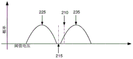
Fig. 2A through 2D illustrate example threshold voltage distributions for 0/1 equilibrium recovery. Fig. 2A and 2B are SLC specific examples showing threshold voltage distributions at a first and later second time, respectively. Fig. 2C and 2D are MLC specific examples showing threshold voltage distributions at a first and later second time, respectively.
Fig. 3A shows selected details of a system implementation of the SSD example of fig. 1A, providing specific details regarding 0/1 balance management.
FIG. 3B shows selected details of read cell organization for the embodiment of FIG. 3A.
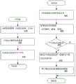
Fig. 4 shows selected control flow details of the SSD implementations of fig. 1A, 1B, and 3, providing specific details regarding write-related operations (operations 410-430) and read-related operations (operations 440-480).
List of element numbers in the drawings
| Element number | Name of |
| 100 | Solid state hard disk controller |
| Element number | Name of |
| 101 | |
| 102 | Main unit |
| 103 | (optional) switch/ |
| 104 | |
| 105 | |
| 106 | Firmware (FW) |
| 107 | Drive the |
| 107D | Dotted arrow (host software ← → I/O device communication) |
| 109 | Applications of |
| 109D | Dotted arrow (application ← → I/O device communication by driver) |
| 109V | Dotted arrow (application ← → I/O device communication through VF) |
| 110 | |
| 111 | |
| 112C | (optional) memory card |
| 113 | Tag tracking |
| 114 | Multi-device management software |
| 115 | Host software |
| 116 | I/O card |
| 117 | I/O and storage devices/ |
| 118 | |
| 119 | Local area network/wide area network |
| 121 | Data processing |
| 123 | |
| 131 | |
| 133 | |
| 135 | ECC-X |
| 137 | |
| 141 | Mapping |
| Element number | Name of element |
| 143 | Watch (A) |
| 151 | |
| 161 | |
| 171 | CPU |
| 172 | |
| 173 | Instruction management |
| 175 | |
| 177 | |
| 179 | |
| 180 | Storage interface |
| 181 | |
| 182 | |
| 190 | |
| 191 | Device interface logic |
| 192 | |
| 193 | |
| 194 | |
| 199 | |
| 210 | SLC |
| 215 | SLC adjusted |
| 220 | SLC nominal most |
| 225 | SLC offset most |
| 230 | SLC nominal most |
| 235 | SLC offset most |
| 240 | MLC nominal |
| 242 | MLC nominal |
| 244 | MLC nominal |
| 250 | MLC nominal most negative threshold state |
| Element number | Name of |
| 251 | MLC adjusts most |
| 260 | MLC nominal sub-most |
| 261 | MLC adjust sub-most |
| 265 | MLC adjusts |
| 270 | MLC nominal |
| 271 | MLC adjust |
| 275 | MLC adjusting |
| 280 | MLC nominal most |
| 281 | MLC adjust most |
| 285 | MLC adjusting third read threshold |
| 306 | |
| 310 | Scrambling device |
| 311 | Scrambled |
| 320 | |
| 321 | ECC encoded |
| 332 | |
| 334 | Programmable read- |
| 336 | Control/status register |
| 338 | I/ |
| 340 | |
| 341 | Unbalance |
| 351 | |
| 359 | Uncorrected and scrambled (Raw) read |
| 360 | ECC decoder |
| 361 | Correcting read data |
| 362 | Uncorrected read |
| 370 | Descrambling device |
| 371 | Unscrambled read data |
| Element number | Name of |
| 380 | Balanced repair logic |
| 410 | |
| 420 | ECC encoding |
| 430 | Writing to |
| 440 | |
| 450 | Data recovery |
| 460 | Uncorrectable errorsEvaluation of |
| 470 | |
| 480 | Read threshold adjustment |
Detailed Description
In the following, reference will now be made in detail to various embodiments of the invention, examples of which are illustrated in the accompanying drawings and described below. While the present disclosure is described in conjunction with the exemplary embodiments, it will be understood that this description is not intended to limit the disclosure to those exemplary embodiments. On the contrary, the invention is intended to cover not only these exemplary embodiments, but also various alternatives, modifications, equivalents and other embodiments, which may be included within the spirit and scope of the invention as defined by the appended claims.
A detailed description of one or more embodiments of the invention is provided below along with accompanying figures that illustrate selected details of the invention. The invention has been described in connection with the embodiments. The embodiments herein are to be considered merely illustrative, and the invention is not explicitly limited or restricted to some or all of the embodiments mentioned herein, and the invention includes many alternatives, modifications and equivalents. To avoid a monotonic discussion, labels for various words (including but not limited to: first, last, certain, multiple, further, other, specific, select, certain, and significant) can also be applied to a separate set of embodiments; labels, as used herein, are expressly not meant to convey quality, or any form of preference or bias, but merely to facilitate distinction between separate sets. The order of certain operations of disclosed methods may be altered within the scope of the invention. Other embodiments contemplate that statically and/or dynamically selecting multiple modes of operation according to predetermined or dynamically determined criteria correspond to multiple complex embodiments, respectively, so long as multiple embodiments are used to describe variations in process, method, and/or program instruction features. In the following description, numerous specific details are set forth in order to provide a thorough understanding of the present invention. The details are provided for the purpose of example and the invention may be practiced according to the claims without some or all of these details. For the purpose of clarity, technical material that is known in the technical fields related to the invention has not been described in detail so that the invention is not unnecessarily obscured.
Introduction to the design reside in
This introduction is merely included to facilitate a more rapid understanding of particular embodiments; the invention is not limited to the concepts presented in the introduction (including the explicit embodiments, if any), as any section of the introduction is necessarily a shorthand view of the entire subject matter and is not meant to be an exhaustive or limiting description. For example, the following introduction provides summary information and organization of only certain embodiments as a result of space limitations. There are many other embodiments, including those in which the claims will ultimately be described and discussed throughout the balance of the specification.
Abbreviations
At least some of the abbreviated abbreviations (e.g., acronyms) that differ with reference to certain elements used herein are defined herein.

| Abbreviations | Description of the invention |
| DES | Data encryption standard |
| DMA | Direct memory access |
| DNA | Direct NAND access |
| DRAM | Dynamic random access memory |
| DVD | Digital multifunctional/video disc |
| DVR | Digital video recorder |
| ECC | Error correcting code |
| eMMC | Embedded multimedia card |
| eSATA | External serial advanced technology attachment |
| GPS | Global positioning system |
| HDD | Hard disk drive |
| I/O | Input/output |
| IC | Integrated circuit with a plurality of transistors |
| IDE | Electronic integrated driver |
| JPEG | Joint image expert group |
| LAN | Local area network |
| LB | Logic block |
| LBA | Logical Block Address |
| LDPC | Low density parity check |
| LFSR | Linear feedback shift register |
| LPN | Logical page number |
| LSB | Least significant bit |
| LZ | Lempel-Ziv compression algorithm |
| MLC | Multi-layer unit |
| MMC | Multimedia card |
| MPEG | Moving Picture experts group |
| MSB | Most significant bit |
| NAS | Network attached storage |
| Abbreviations | Description of the invention |
| NCQ | Native command queue |
| NVM | Nonvolatile memory |
| ONA | Optimized NAND access |
| ONFI | Open NAND flash memory interface |
| OS | Operating system |
| PC | Personal computer |
| PCIe | Peripheral component interconnect express (PCI express) |
| PDA | Personal digital assistant |
| PHY | Physical interface |
| POS | Point of sale |
| RAID | Redundant array of inexpensive/independent disks |
| RASIE | Silicon element independent redundant array |
| ReRAM | Resistive random access memory |
| RS | Reed-solomon |
| RSA | Uster, Samil and Edman |
| SAN | Attached network storage |
| SAS | Serial connection small computer system interface (serial SCSI) |
| SATA | Serial advanced technology attachment (Serial ATA) |
| SCSI | Small computer system interface |
| SD | Secure digital |
| SDR | Single data rate |
| SLC | Single layer unit |
| SMART | Self-monitoring analysis and reporting techniques |
| SSD | Solid state disk/drive |
| TCG | Trusted computing group |
| UFS | Unified flash storage |
| USB | Universal serial bus |
| VF | Virtual functions |
| Abbreviations | Description of the invention |
| WAN | Wide area network |
Tracking and recovery 0/1 balancing
In the initial discussion below, tracking and managing 0 and 1 counts and the shift of the state read thresholds to distinguish between 0 and 1 may be applied directly to the lower pages of SLC and (slightly changed, noted) MLC memory. More generally for MLC memory, extended tracking and management of upper page counts and shifts of multiple read thresholds (e.g., read reference voltage V)READ1、VREAD2And VREAD3) Detailed in separate paragraphs below.
In some embodiments, a count of 0 and a count of 1 are obtained for each read cell (or one offset per group of read cells from the NVM chip) from NVM read of SLC. The read cells are uncorrectable in the event that, in part, the threshold voltage distribution shifts from the (initial) nominal distribution, 0 counts and/or 1 counts can determine direction and/or magnitude to move the read threshold (read reference voltage V)READ1) To track the offset threshold voltage distribution and restore 0/1 equilibrium. Read threshold adjusted to read reference voltage V for SLC memoryREAD1And a read reference voltage V for the lower page of the MLC memoryREAD2. For example, in SLC a logic 1 is assigned to the erased state and written toWith known statistically equal 0 and 1 distributions (50-50%, aka 50/50%, or only 50/50), V predominates if 0/1 counts the current to indicate that 1 predominatesREAD1Shifting to low; if 0/1 counts the current to indicate that 0 dominates, VREAD1Shift to high. (in the above example, V was replacedREAD2Is a VREAD1For the lower page of MLC memory. ) What the magnitude of the changing (offset) read threshold is optionally determined by a percentage of the number of 0 (or 1). The amplitude is based on one or more of: the number of 0 s and/or 1 s observed in one or more samples; read threshold voltage increments for one or more samples; knowledge of a predicted threshold voltage distribution corresponding to a midpoint between the vertices of the two distributions; program/erase counts (wear); reading the interference count; a retention time; and other similar factors.
Finding read balance points
In a further embodiment, the operation of binary search approximation (repeated sampling of the same read cell with the corresponding value of the appropriate read reference voltage) is used to find the read threshold "read balance point". This is the point of the threshold voltage axis between adjacent threshold voltage distributions of the raw data (pre-error correction) statistical state distribution being read, the statistical difference in error within the state of the matching written statistical distribution, or the same idealized model.
For SLC memory and random scrambling, as derived from encryption, the read balance point is the read threshold (read reference voltage V)READ1) Where 0/1 balances (raw data read from NVM) are most uniform (nearly identical). In this case, the two state distributions exhibit a 50-50 balance. That is, 50% of the read states are 0 and 50% of the read states are 1. (in the above example, V was replacedREAD2Is a VREAD1For the lower page of MLC memory. )
In some embodiments, the read balance points correspond to one or more of: the center point between the two voltage distributions, the minimum between the two voltage distributions, the point of equilibrium at 0/1 of the read data is closest to 50-50, and the point determined from the interpolation of the equilibrium found 0/1 at the other two points. The read balance point corresponds to the center point between adjacent threshold voltage distributions in an embodiment with symmetric adjacent threshold voltage distributions.
Finding and setting the read threshold for the required read balance point reduces the number of reads required to find the best point to attempt hard decision decoding. In yet another embodiment, hard decision decoding attempts at every read threshold sampling point (V for SLC memory)READ1Or V for the lower page of MLC memoryREAD2Each value of) in the binary search in the event that a "good enough" read threshold is found before a read threshold read balance point is found. The search is typically terminated when a sufficiently good read threshold is found, except for additional sampling that may be taken around the determined read balance point for soft decision decoding purposes, as discussed below. In various embodiments, a "good enough" read threshold is the result of a successful hard decision decoding of the read data. In some embodiments, the magnitude of the search step (increment of read threshold voltage) in the binary search is determined (based), and the magnitude of the change in read threshold voltage is based, at least in part, on the various factors detailed above.
Notes on MLC
In MLC memory, multiple read thresholds are managed. In some embodiments, this is by assuming a uniform shift of the multiple device threshold voltage distributions and a first read threshold (V) balanced for the lower page based read data 0/1READ1) All other read thresholds are changed on the basis of the decision being made.
For NVM of 4LC, there is theoretically 11/10/00/01 balance of 25-25-25-25 (balanced with 0/1 of 50-50). However, there is no single operation to provide this balance directly, since 4LCs are typically read by two separate read operations using three read reference voltages: vREAD2Corresponding to the lower page and VREAD1And VREAD3Corresponding to the upper page. Two respective 0/1 balances can thus be evaluated: the lower page corresponds between the D1 and D2 states, while the upper page corresponds between the E and D1 states in conjunction with the D2 and D3 states. In addition, three separate lower page approximate reads may be performed to set a single lower page read threshold to be close to VREAD1、VREAD2And VREAD3Each value of (a).
By way of example, in some 4LC NVM embodiments, a read reference voltage VREAD1、VREAD2And VREAD3An offset may be required, at least for one of the two bits in the memory cell. Similar to the operation in the SLC case, one of the two bits stored in the cell needs to be at the first read threshold (V)READ2In this MLC case) are read separately. Two additional read thresholds (V) are required to determine other bitsREAD1And VREAD3And two associated respective additional reads that are effectively performed internally by the NVM).
According to various embodiments, either: two read thresholds (V) for other bitsREAD1And VREAD3) Are uniformly moved by the same and/or different amounts (based on similar presumptions of two-state drift); or the two read thresholds for the other bits are independently shifted (extra read operation cost). The latter option requires knowledge of the state of the SLC like bit (LSB) in the cell, since the state of the SLC like bit determines the two read thresholds (V)READ1And VREAD3) One of which is used to determine the corresponding other bit (MSB).
In some 4LC implementations, the combined "upper page" read data 0/1 balance was evaluated for a fusion of both the E and D1 distributions and the D2 and D3 distributions. Balance the gap between read and write based on the combination 0/1, and take into account the reversal of bit sense (E moving to 1-0 as D1, D2 moving to 0 as D3), the corresponding two read thresholds (V)READ1And VREAD3) Move in unison in opposite directions. This allows 0/1 of the mixing assembly to move "in the same direction" in equilibrium (e.g., without conflicting movements).
In some 4LC implementations, two upper page read thresholds (V)READ1And VREAD3) Are determined by balancing the respective evaluations against the upper page 0/1 to use the corresponding LSB for each bit of the read cell. When LSB is 1, the moving direction is opposite to the case where LSB is 0. For example, instead of calculating the difference between the count of 0 and the count of 1 in the upper page read data, the difference of the upper page is calculatedThe bit sense of the upper page read data is transformed from a magnitude value to an orientation value, e.g., 0 represents a higher threshold voltage and 1 represents a lower threshold voltage, calculated by selectively modifying each bit of the upper page read data based on the corresponding lower page read data bit. In some implementations, an exclusive nor (XNOR) of the upper page read data bits is converted with the corresponding lower page read data bits.
Removing bias from soft decision samples
In some embodiments, the soft decision information obtained from the NVM is used to perform decoding-based soft decisions. Soft decision information (SLC, V) obtained from read cells (or one offset per group of read cells from NVM chip) read at multiple read threshold sampling pointsREAD1Value of) is close to a nominal (unadjusted) read threshold to obtain multiple samples of read cell data, thereby establishing the possibility of soft decision reading the value of each bit of the cell. The pitch of the samples depends at least in part on the particular properties of the NVM used, such as the nominal charge separation state.
However, the soft decision information is the bias unless those nominal read thresholds at which the samples are taken are the read balance points of the read thresholds (as described above). If the current read threshold is not the threshold read balance point, then all of the soft decision information is biased in one direction or the other. There are two ways to adjust to obtain unbiased (or at least less biased) soft decision information:
1. since the 0/1 balance of the read cells sampled at the sample point of each read threshold is easily identified, the read balance point of the read threshold is easily determined (according to an embodiment, for example, by using linear interpolation). The offset is calculated as the difference between the read balance point corresponding to the determined read threshold and the (old, unadjusted) nominal read threshold. The previously determined soft decision information is enabled for proper "re-centering" and the associated voltage offset still passing through the previously sampled soft decision information is used (truncated with a value greater than 1.0 or less than 0.0). This approach does not require additional reads, but produces some data of varying amounts of precision/accuracy.
2. Since the 0/1 balance of the read cell sampled at each read threshold sampling point is easily identified, after all necessary samples are collected, the read balance point at which the read threshold sampling point is closest to the read threshold is easily determined. It is closest that 0/1 balances the read threshold sampling points closest to the write 0/1 balance. In the case of encryption (or scrambling) of SLC, the read threshold sampling point is closest to having a balance of 50-50. Since all samples are nominally equally spaced from each other, the closest sample is selected as the new nominal read threshold, and additional samples of soft decision information are optionally aggregated (assuming the new nominal read threshold is different from the old). In addition, firstly, binary search is completed to find a threshold value reading balance point, and the accurate binary search is used for limiting the optimal granularity of sampling according to the accuracy requirement required by the soft decision information. The required accuracy of the soft decision information has an associated sampling window around the new nominal read threshold. Binary searching of the multiple read portions requires obtaining soft decision information without additional reads unless the old nominal read threshold falls outside the desired precision sample window.
In the SLC encryption implementations described so far, the above techniques have all focused on finding the preferred read threshold that yields a balance of read data 0/1 closest to 50-50. In the case where the threshold voltage distributions are substantially the same symmetrical shape and there is no substantial overlap, this preferred read threshold voltage will also correspond to the minimum of the combined threshold voltage distributions.
Read threshold interpolation from known point threshold voltage distributions
In some embodiments, another way to find the preferred read threshold is to instead find two points, one on each adjacent threshold voltage distribution, and determine the midpoint between the two points by interpolation. For example, sampling at the peak of each threshold voltage distribution should produce a 75:25 balance (or 1/0, depending on which peak) of the read data 0/1. Once these two peaks are determined, the midpoint calculated between the two pairs of threshold voltage axes is used to set the new read threshold.
If the earlier threshold voltage distributions are known to be non-uniform (e.g., asymmetrically biased to one side or the other, such as with a long tail), then the information in some embodiments is used to interpret the location of the peak and locate the center by a slightly more complex interpolation (e.g., not just the midpoint). Factors such as retention time and/or wear can affect the symmetry of the threshold voltage distribution and can be identified in some embodiments. Multiple sampling points are also used in some implementations to show the shape of the threshold voltage distribution.
The range of threshold voltage adjustment is limited in some implementations and a true peak may not be found. Especially below 0V the threshold voltage cannot be moved and some flash memory devices extend through the voltage distribution of the E-state to the negative threshold voltage. Knowledge of the threshold voltage distribution still allows the midpoint to be determined by interpolation. For example, if the read data 0/1 equilibrium is 60/40 at 0V, then approximately 10% excess of 0 is observed and the area of the E distribution to the right of 0V is approximately 10%. In a first approach of some embodiments, the peaks of the D1 distribution are found and the midpoints are inserted based on knowledge of the approximate shape of the E distribution. In a second approach of some embodiments, the point at which the read data 0/1 balanced the D1 distribution of 40/60 (relative point measured from 0V) was found. The calculated midpoint between the 60/40 and 40/60 observations is then used to set a new preferred read threshold. The calculated intermediate point may be determined with additional knowledge of the two threshold voltage distributions and/or with higher accuracy measurements.
In some embodiments the inserted points are all on the same side of the read balance point. For example, knowing that the first read threshold sample point X yields a 0/1 balance of 75/25 read data and the second read threshold sample point Y yields 62.5/37.5, the read balance point is approximately Y +/- (X-Y) where "+" and "-" depend on whether Y is less than X. The direction of the read balance point is the direction corresponding to the read data 0/1 moving closer to 50/50 being balanced. In the example given, i.e. from X and in the direction Y. Knowledge of the threshold voltage distribution will produce a more accurate interpolation rather than the simple linear interpolation shown.
Detailed Description
In the detailed description that follows in summarizing the introduction, this is followed by a collection of exemplary embodiments, including at least some explicitly listed as "ECs" (Example Combinations), additional description of various embodiment types is provided in accordance with the concepts described herein; these embodiments are not meant to be mutually exclusive, exhaustive, or limiting; and the invention is not limited to these exemplary embodiments but covers all possible modifications and variations within the scope of the granted claims and their equivalents.
EC1) a method comprising:
determining a difference between a number of 0 s and a number of 1 s for at least one or more reads of the NVM; and
subsequent differences are reduced by selectively shifting threshold voltages based at least in part on the determined differences, corresponding to uncorrectable reads in the NVM.
EC2) the method of EC1, further comprising:
wherein the NVM is an MLC memory having a plurality of states, each state having an associated MSB and LSB value in accordance with a prescribed gray code mapping, the one or more reads of the NVM being MSB reads; and
wherein determining the difference comprises using the LSB read to selectively invert data of the MSB read corresponding to the one or more MSB reads.
EC3) the method of EC1, wherein each of the at least one or more reads is an independent read of at least a portion of a corresponding page in the NVM.
EC4) the method of EC1, wherein determining the difference comprises determining a difference between a number of 0 s and a number of 1 s.
EC5) the method of EC1, wherein the number of 0 s and the number of 1 s are respectively determined by corresponding counting.
EC6) the method of EC4, wherein the shifting is not performed if an absolute value of the difference is lower than a predetermined amount.
EC7) the method of EC1, wherein the shifting is performed by a predetermined voltage if an absolute value of the difference is lower than a predetermined amount.
EC8) the method of EC1, wherein the direction of the shift in the threshold voltage is based at least in part on a mapping of logic states to NVM charge states.
EC9) the method of EC1, wherein the NVM is SLC memory having a logical 1 to erased state mapping, and the threshold voltage shift down is based at least in part on a determination that the number of 0 s is less than the number of 1 s.
EC10) the method of EC9, wherein the further downward shift in the threshold voltage is based at least in part on a determination that the difference exceeds a predetermined amount.
EC11) the method of EC1, wherein the NVM is SLC memory having a logical 1 to erased state mapping, and the threshold voltage shift down is based on a determination that the difference indicates that 1 dominates.
EC12) the method of EC1, wherein the NVM is SLC memory having a logical 1 to erased state mapping, and the threshold voltage shift up is based at least in part on a determination that the number of 0 s is more than the number of 1 s.
EC13) the method of EC12, wherein the difference is more than a predetermined amount.
EC14) the method of EC1, wherein the NVM is SLC memory having a logical 1 to erased state mapping, and the threshold voltage shift up is based on a determination that the difference indicates that 0 dominates.
EC15) the method of EC4, wherein the number of 0 s and the number of 1 s used in the difference are based on a plurality of reads.
EC16) the method of EC1, wherein the determining is performed at each of a plurality of threshold voltages, and the shifting is based at least in part on the determined differences.
EC17) an apparatus comprising:
means for determining a difference between the number of 0 s and the number of 1 s for at least one or more reads of the NVM; and
means for reducing subsequent differences by selectively shifting threshold voltages based at least in part on the determined differences in response to uncorrectable reads from the NVM.
EC18) the apparatus of EC17, further comprising:
wherein the NVM is an MLC memory having a plurality of states, each state having an associated MSB and LSB value in accordance with a prescribed gray code mapping, the one or more reads of the NVM being MSB reads; and
wherein the means for determining the difference comprises means for using the LSB read corresponding to the one or more MSB reads to selectively invert the data of the MSB reads.
EC19) the apparatus of EC17, wherein each of the at least one or more reads is an independent read of at least a portion of a corresponding page in the NVM.
EC20) the apparatus of EC17, wherein determining the difference comprises determining a difference between a number of 0 s and a number of 1 s.
EC21) the apparatus of EC17, wherein the number of 0 s and the number of 1 s are respectively determined by corresponding counts.
EC22) the apparatus of EC20, wherein the shifting is not performed if an absolute value of the difference is lower than a predetermined amount.
EC23) the apparatus of EC20, wherein the number of 0 s and the number of 1 s used in the difference are based on a plurality of reads.
EC24) the method of EC17, wherein the determining is performed at each of a plurality of threshold voltages, and the shifting is based at least in part on the determined differences.
EC25) a method comprising:
determining differences, each difference having a respective magnitude and a difference of a respective known distribution stored in the NVM and a corresponding value read from the NVM; and
periodically in response to an uncorrectable read from the NVM, selectively shifting at least one read threshold voltage based at least in part on the at least one determined difference prior to shifting.
EC26) the method of EC25, wherein each periodic offset value of the at least one read threshold voltage is determined targeting a respective magnitude of at least one determined difference that remains below a predetermined amount after the offset.
EC27) the method of EC26, wherein, at least until a next uncorrectable read, the respective magnitude of the at least one determined difference after the shift is reduced below a predetermined amount by the at least one read threshold of the single update.
EC28) the method of EC25, wherein the NVM is SLC.
EC29) the method of EC25, wherein the NVM is MLC.
EC30) the method of EC29, wherein the MLC is a 4LC MLC, and the difference is evaluated in at least two states of the E state and the number of D states.
EC31) the method of EC29, wherein the MLC is a 4LC MLC and is known to be distributed among four states 25-25-25-25%.
EC32) the method of EC25, wherein the NVM is an MLC having a plurality of states, each state having an associated value of an MSB and an LSB in accordance with a prescribed gray code mapping, the at least one threshold voltage offset is in view of a determined difference being performed with respect to a lower page read, and a dominant voltage offset corresponding to a difference of 0 is in a first direction and a dominant voltage offset corresponding to a difference of 1 is in a second direction.
EC33) the method of EC25, wherein the NVM is an MLC having multiple states, each state has an associated value of an MSB and an LSB in accordance with a prescribed gray code mapping, and the at least one threshold voltage offset is in view of a determined difference in reading on an upper page being performed.
EC34) the method of EC33, wherein the reading of the upper page for the determined difference is performed using a specific LSB for each bit of the read cell, and the direction sense for the first LSB value voltage offset is opposite for a first LSB value voltage offset that is dominant for a difference of 0 in a first direction and dominant for a difference of 1 in a second direction.
EC35) the method of EC33, wherein the upper page reading for the determined difference is performed using a particular LSB for each bit of the read cell, and the direction of the voltage offset is determined based at least in part on the particular LSB value of the upper page reading and based at least in part on the nature of the difference.
EC36) the method of EC25, wherein the NVM is an MLC having an E-state and a plurality of D-states, and at least one threshold voltage is between the E-state and a selected one of the plurality of D-states.
EC37) the method of EC25, wherein the NVM is an MLC having an E-state and a plurality of D-states, and at least one threshold voltage is between selected two adjacent D-states of the plurality of D-states.
EC38) the method of EC25, further comprising:
wherein the NVM is an MLC memory having a plurality of states, each state having an associated MSB and LSB value is mapped according to a prescribed gray code, and for values read from the NVM, the read is an MSB read; and
wherein determining the difference comprises using the LSB read to selectively invert data of the MSB read corresponding to the one or more MSB reads.
EC39) an apparatus comprising:
determining differences, each difference having a respective magnitude and a difference of a respective known distribution stored in the NVM and a corresponding value read from the NVM; and
means for selectively shifting at least one read threshold voltage prior to shifting based at least in part on the at least one determined difference in response to an uncorrectable read from the NVM periodically.
EC40) the method of EC39, wherein each periodic offset value of the at least one read threshold voltage is determined targeting a respective magnitude of at least one determined difference that remains below a predetermined amount after the offset.
EC41) the apparatus of EC40, wherein, at least until a next uncorrectable read, the respective magnitude of the at least one determined difference after the shift is reduced below a predetermined amount by the at least one read threshold of the single update.
EC42) the device of EC39, wherein the NVM is SLC.
EC43) the apparatus of EC39, wherein the NVM is MLC.
EC44) a method comprising:
determining a difference in a count of 0 and a count of 1 in each of the one or more portions of the data read from the NVM;
wherein each determination of read reference voltage settings at a plurality of read thresholds is performed and a difference is calculated;
calculating a threshold center point using the calculated difference of the interpolation; and
the read threshold is shifted based at least in part on the calculated threshold center point to update the read reference voltage setting.
EC45) the method of EC44, wherein the interpolation is a linear interpolation.
EC46) the method of EC44, wherein determining the difference comprises determining a count of 0 and a count of 1 for at least one or more reads of the previously calculated NVM to calculate a difference of a count of 0 and a count of 1.
EC47) an apparatus comprising:
means for determining a difference in a count of 0 and a count of 1 in each of one or more portions of a data read from the NVM, wherein each determination of a read reference voltage setting at a plurality of read thresholds is performed and a difference value is calculated;
means for calculating a threshold center point using the calculated interpolated difference; and
means for shifting the read threshold based at least in part on the calculated threshold center point to update the read reference voltage setting.
EC48) the apparatus of EC47, wherein the interpolation is a linear interpolation.
EC49) the apparatus of EC47, the determining the difference comprising means for determining a count of 0 and a count of 1 for at least one or more reads of the previously calculated NVM to calculate a difference of the count of 0 and the count of 1.
EC50) a method comprising:
reading data of the same read cell in each of the plurality of threshold voltages;
determining a read count of 0 and a read count of 1 for each read of the same read unit;
calculating a threshold center point based at least in part on the read count; and
soft decision information is generated based at least in part on the data reading and the calculated threshold center point.
EC51) the method of EC50, wherein the calculation of the threshold center point is performed at least in part using an interpolation calculated from a difference of a read count of 0 and a read count of 1.
EC52) the method of EC51, wherein the interpolation is a linear interpolation.
EC53) the method of EC50, wherein the values of the plurality of soft decision information are generated based on reading out respective threshold voltage shift data with respect to a calculated threshold center point.
EC54) the method of EC53, wherein the even-numbered values yield equal amounts corresponding to respective voltage shifts above and below the calculated threshold center point.
EC55) the method of EC53, wherein the use of the threshold center point calculated as a reference for generating the soft decision information improves validity of the soft decision information currently generated by reducing the deviation.
EC56) an apparatus comprising:
means for reading data of the same read cell in each of the plurality of threshold voltages;
means for determining a read count of 0 and a read count of 1 for each read of the same read unit;
calculating a threshold center point based at least in part on the read counts; and
means for generating soft decision information based at least in part on the data reading and the calculated threshold center point.
EC57) the apparatus of EC56, wherein the calculation of the threshold center point is performed at least in part using an interpolation calculated from a difference of a read count of 0 and a read count of 1.
EC58) the apparatus of EC57, wherein the interpolation is a linear interpolation.
EC59) the apparatus of EC56, wherein the values of the plurality of soft decision information are generated based on reading out respective threshold voltage shift data with respect to a calculated threshold center point.
EC60) the apparatus of EC59, wherein the even-numbered values yield equal amounts corresponding to respective voltage shifts above and below the calculated threshold center point.
EC61) the apparatus of EC59, wherein the use of the threshold center point calculated as a reference for generating the soft decision information improves validity of the soft decision information currently generated by reducing the deviation.
EC62) a method comprising:
reading data of the same read cell in each of the plurality of threshold voltages;
determining a count of 0 and a count of 1 for each read of the same read unit;
determining a midpoint threshold voltage that is closest to the plurality of threshold voltages based at least in part on the read counts, the midpoint threshold voltage closest to the midpoint corresponding to a conceptual threshold midpoint; and
soft decision information is generated based at least in part on the reading of the data and the identified nearest center point threshold voltage.
EC63) the method of EC62, wherein the calculation of the threshold center point is performed at least in part using an interpolation calculated from a difference of a read count of 0 and a read count of 1.
EC64) the method of EC63, wherein the interpolation is a linear interpolation.
EC65) the method of EC62, wherein the values of the plurality of soft decision information are generated based on reading out respective threshold voltage shift data with respect to a calculated threshold center point.
EC66) the method of EC65, wherein the time intervals determined corresponding to the respective voltage shifts yield values.
EC67) the method of EC62, wherein the use of the threshold center point calculated as a reference for generating the soft decision information improves validity of the soft decision information currently generated by reducing the deviation.
EC68) an apparatus comprising:
means for reading data of the same read cell in each of the plurality of threshold voltages;
means for determining a count of 0 and a count of 1 for each read of the same read unit;
means for determining a midpoint threshold voltage that is closest to the plurality of threshold voltages based at least in part on the read counts, the midpoint threshold voltage closest to the midpoint corresponding to the conceptual threshold midpoint; and
means for generating soft decision information based at least in part on the reading of the data and the identified nearest center point threshold voltage.
EC69) the apparatus of EC68, wherein the calculation of the threshold center point is performed at least in part using an interpolation calculated from a difference of a read count of 0 and a read count of 1.
EC70) the apparatus of EC69, wherein the interpolation is a linear interpolation.
EC71) the apparatus of EC68, wherein the values of the plurality of soft decision information are generated based on reading out respective threshold voltage shift data with respect to a calculated threshold center point.
EC72) the apparatus of EC71, wherein the time intervals determined corresponding to the respective voltage offsets yield values.
EC73) the apparatus of EC68, wherein the use of the threshold center point calculated as a reference for generating the soft decision information improves validity of the soft decision information currently generated by reducing the deviation.
EC74) a method comprising:
storing data in the NVM, wherein the stored data has a particular balance of 0-1;
maintaining a count of 0 and a count of 1, wherein the count of 0 and the count of 1 are read counts;
evaluating the 0-1 balance of the NVM as a function of the count of 0, the count of 1, and the particular 0-1 balance;
after determining from the uncorrectable read from the NVM that the 0-1 balance is outside the prescribed range, shifting the threshold voltage to the determined value based at least in part on the evaluating and with as little threshold voltage shift as possible in accordance with a goal of restoring the 0-1 balance to within the prescribed range; and
where data recovery from the NVM is optimized.
EC75) the method of EC74, further comprising:
wherein the shift of the threshold voltage is a shift to a low voltage based on a determination of a 0-1 balance including an excess of 1 relative to a particular 0-1 balance; and
wherein the shift of the threshold voltage is a shift to a high voltage is based on a determination of a 0-1 balance including an excess of 0 relative to a particular 0-1 balance.
EC76) the method of EC74, wherein the data is stored using an encryption method and the specific 0-1 balance is 50% of 0 and 50% of 1.
EC77) the method of EC74, wherein the specific 0-1 balance corresponds to less than 55% of 0 and more than 45% of 1.
EC78) the method of EC74, wherein the probability that a particular 0-1 balance corresponds to more than 52.5% zeros is less than one ten thousandth.
EC79) the method of EC74, wherein the particular 0-1 balance corresponds to less than 45% of 0 and greater than 55% of 1.
EC80) an apparatus comprising:
storing data in the NVM, wherein the stored data has a particular 0-1 balanced device;
means for maintaining a count of 0 and a count of 1, wherein the count of 0 and the count of 1 are read counts;
means for evaluating a 0-1 balance of the NVM as a function of the count of 0, the count of 1, and a particular 0-1 balance;
means for shifting the threshold voltage to a determined value based at least in part on the evaluation and with as little threshold voltage shift as possible based on restoring 0-1 balance to a target within the prescribed range after uncorrectable reads from the NVM and determining that the 0-1 balance is outside the prescribed range; and
where data recovery from the NVM is optimized.
EC81) the apparatus of EC80, further comprising:
wherein the shift of the threshold voltage is a shift to a low voltage based on a determination of a 0-1 balance including an excess of 1 relative to a particular 0-1 balance; and
wherein the shift of the threshold voltage is a shift to a high voltage is based on a determination of a 0-1 balance including an excess of 0 relative to a particular 0-1 balance.
EC82) the apparatus of EC80, wherein the data is stored using an encryption method and the specific 0-1 balance is 50% of 0 and 50% of 1.
EC83) the apparatus of EC80, wherein the specific 0-1 balance corresponds to 0 below 55% and 1 above 45%.
EC84) the apparatus of EC80, wherein the probability that a particular 0-1 balance corresponds to more than 52.5% zeros is less than one ten thousandth.
EC85) the apparatus of EC80, wherein the particular 0-1 balance corresponds to less than 45% of 0 and greater than 55% of 1.
EC86) a method comprising:
scrambling data written to a portion of the non-volatile memory to produce scrambled data having a known statistical average of 0 bits and a known statistical average of 1 bit;
writing the scrambled data to a portion of the non-volatile memory;
after the writing, reading a portion of the non-volatile memory;
calculating a difference between a number of 0 bits and a number of 1 bits in data read from a portion of the non-volatile memory; and
the threshold voltage is determined based at least in part on a subsequent read of the differential non-volatile memory.
EC87) the method of EC86, wherein the determining is further based on a known statistical average of 0 bits or a known statistical average of 1 bit.
EC88) the method of EC86, further comprising:
portions of the non-volatile memory are re-read using the threshold voltage.
EC89) the method of EC88, wherein the writing comprises encoding the scrambled data using an ECC encoder and writing the encoded scrambled data to the portion of the non-volatile memory, and further comprising:
prior to re-reading, the data read from the portion of the non-volatile memory is decoded using an ECC decoder to determine that the data read from the portion of the non-volatile memory is uncorrectable.
EC90) the method of EC89, wherein the difference is a first difference, the threshold voltage is a first threshold voltage, and further comprising:
decoding, with an ECC decoder, data re-read from the portion of the non-volatile memory using the first threshold voltage to determine that the data re-read from the portion of the non-volatile memory using the first threshold voltage is uncorrectable;
calculating a second difference between the number of 0 bits and the number of 1 bits in the data re-read from the portion of the non-volatile memory using the first threshold voltage; and
a second threshold voltage is determined for a second re-read of the non-volatile memory based at least in part on the first difference and the second difference.
EC91) the method of EC90, further comprising:
the portion of the non-volatile memory is re-read using the second threshold voltage.
EC92) the method of EC89, wherein the ECC encoder adds one or more bytes to the scrambled data, and wherein the one or more bytes added by the ECC encoder have a known statistical average of 0 bits and a known statistical average of 1 bit.
EC93) an apparatus comprising:
means for scrambling data written to the portion of the non-volatile memory to produce scrambled data having a known statistical average of 0 bits and a known statistical average of 1 bit;
means for writing scrambled data to a portion of the non-volatile memory;
means for reading a portion of the non-volatile memory after the writing;
means for calculating a difference between a number of 0 bits and a number of 1 bits in data read from a portion of the non-volatile memory; and
means for determining a threshold voltage for a subsequent read of the non-volatile memory based, at least in part, on the difference.
EC94) the apparatus of EC93, wherein the determining is further based on a known statistical average of 0 bits or a known statistical average of 1 bit.
EC95) the apparatus of EC93, further comprising:
means for re-reading portions of the non-volatile memory using the threshold voltage.
EC96) the apparatus of EC95, wherein the writing comprises encoding the scrambled data using an ECC encoder and writing the encoded scrambled data to the portion of the non-volatile memory, and further comprising:
before re-reading, the data read from the portion of the non-volatile memory is decoded using an ECC decoder to determine that the data read from the portion of the non-volatile memory is an uncorrectable device.
EC97) the apparatus of EC96, wherein the difference is a first difference, the threshold voltage is a first threshold voltage, and further comprising:
means for decoding the data re-read from the portion of the non-volatile memory with an ECC decoder using the first threshold voltage to determine that the data re-read from the portion of the non-volatile memory using the first threshold voltage is uncorrectable;
means for calculating a second difference between a number of 0 bits and a number of 1 bits in data re-read from the portion of the non-volatile memory using the first threshold voltage; and
means for determining a second threshold voltage for a second re-read of the non-volatile memory based at least in part on the first difference and the second difference.
EC98) the apparatus of EC97, further comprising:
means for re-reading the portion of the non-volatile memory using the second threshold voltage.
EC99) the apparatus of EC96, wherein the ECC encoder adds one or more bytes to the scrambled data, and wherein the one or more bytes added by the ECC encoder have a known statistical average of 0 bits and a known statistical average of 1 bit.
EC100) a tangible computer-readable medium having stored thereon a set of instructions that, when executed by a processing element, cause the processing element to perform and/or control operations comprising:
scrambling data written to a portion of the non-volatile memory to produce scrambled data having a known statistical average of 0 bits and a known statistical average of 1 bit;
writing the scrambled data to a portion of the non-volatile memory;
after the writing, reading a portion of the non-volatile memory;
calculating a difference between a number of 0 bits and a number of 1 bits in data read from a portion of the non-volatile memory; and
a threshold voltage determined for a subsequent read of the non-volatile memory based at least in part on the difference.
EC101) the tangible computer-readable medium of EC100, wherein the determining is further based on a known statistical average of 0 bits or a known statistical average of 1 bit.
EC102) the tangible computer-readable medium of EC100, the operations further comprising:
portions of the non-volatile memory are re-read using the threshold voltage.
EC103) the tangible computer-readable medium of EC102, wherein the writing comprises encoding the scrambled data using an ECC encoder and writing the encoded scrambled data to the portion of the non-volatile memory, and the operations further comprise:
prior to re-reading, the data read from the portion of the non-volatile memory is decoded using an ECC decoder to determine that the data read from the portion of the non-volatile memory is uncorrectable.
EC104) the tangible computer-readable medium of EC103, wherein the difference is a first difference, the threshold voltage is a first threshold voltage, and the operations further comprise:
decoding, with an ECC decoder, data re-read from the portion of the non-volatile memory using the first threshold voltage to determine that the data re-read from the portion of the non-volatile memory using the first threshold voltage is uncorrectable;
calculating a second difference between the number of 0 bits and the number of 1 bits in the data re-read from the portion of the non-volatile memory using the first threshold voltage; and
a second threshold voltage determined for a second re-read of the non-volatile memory based at least in part on the first difference and the second difference.
EC105) the tangible computer-readable medium of EC104, the operations further comprising:
the portion of the non-volatile memory is re-read using the second threshold voltage.
EC106) the tangible computer-readable medium of EC103, wherein the ECC encoder adds one or more bytes to the scrambled data, and wherein the one or more bytes added by the ECC encoder have a known statistical average of 0 bits and a known statistical average of 1 bit.
System for controlling a power supply
Fig. 1A shows selected details of an SSD101 embodiment, including an SSD controller that manages non-volatile memory using 0/1 balanced recovery, as implemented by NVM elements (e.g., flash memory). SSD controller 100 is communicatively coupled with a host (such as host 102 shown in fig. 1B) via one or more external interfaces 110. According to various embodiments, the external interface 110 is one or more of: an SATA interface; an SAS interface; a PCIe interface; a fibre channel interface; an ethernet interface (e.g., 10 gigabit ethernet); any non-standard version of the aforementioned interface; self-defining an interface; or any other type of interface for connecting storage and/or communication and/or computing devices. For example, in some embodiments, SSD controller 100 includes a SATA interface and a PCIe interface.
Each flash device 192 has, in some embodiments, one or more individual flash chips 194. Depending on the particular class of flash devices 192, multiple flash chips 194 in a particular flash device 192 are optionally and/or selectively accessed in parallel. Flash device 192 is merely representative of one type of storage device that can be communicatively coupled to SSD controller 100. In various embodiments, any type of memory device is usable, such as SLC NAND flash memory, MLC NAND flash memory, NOR flash memory, flash memory using charge storage cells based on polysilicon or silicon nitride technology, two-dimensional or three-dimensional technology based flash memory, read only memory, static random access memory, dynamic random access memory, magnetic memory, phase change memory, racetrack memory, ReRAM, or any other type of memory device or storage medium.
According to various embodiments, the device interface 190 is organized as: one or more buses corresponding to one or more flash memory devices 192 for each bus; one or more sets of buses, one or more flash devices 192 per bus, where a set of buses are typically accessed in parallel; or any other organization of one or more flash memory devices 192 into a device interface 190.
Continuing in fig. 1A, SSD controller 100 has one or more modules, such as host interface 111, data processing 121, buffer 131, map 141, recycle bin 151, ECC161, device interface logic 191, and CPU 171. The specific modules and interconnections shown in fig. 1A represent only one embodiment, and many layouts and interconnections of some or all of the modules, as well as additional modules not shown, are contemplated. In a first example, in some embodiments, there are two or more host interfaces 111 to provide dual porting. In a second example, in some embodiments, data processing 121 and/or ECC161 is combined with buffer 131. In a third example, in some embodiments, host interface 111 is directly coupled to buffer 131, and data processing 121 optionally and/or selectively manipulates data stored in buffer 131. In a fourth example, in some embodiments, device interface logic 191 is directly coupled to buffer 131, and ECC161 optionally and/or selectively operates on data stored in buffer 131.
The instructions and/or data sent and received by the host interface 111 via the external interface 110, and in some embodiments, the progress of the individual instructions is tracked by the tag tracking 113. For example, the instruction includes an address (e.g., LBA) specified by the read instruction and the amount of data to be read (e.g., some LBA quanta, e.g., a sector); read status and/or read data is provided for the SSD. For another example, the instructions include: the address specified by the write instruction (e.g., LBA) and the amount of data to be written (e.g., some LBA quanta, e.g., sector); writes such as status and/or data requested to be written and optionally subsequent write status are provided for the SSD. For yet another example, the instruction includes that one or more addresses (e.g., one or more LBAs) specified by the re-allocation instruction (e.g., the trim instruction) no longer need to be allocated; the mapping is modified accordingly and optionally for the SSD to provide the reallocation status. ATA compliant trim instructions are exemplary reassignment instructions in some cases. For yet another example, the instructions include ultracapacitor test instructions or data hardening success queries; accordingly, the SSD provides the appropriate state. In some embodiments, host interface 111 is compatible using the SATA protocol and, using the NCQ command, enables up to 32 wait commands, each represented using a unique tag from 0 to 31. In some embodiments, tag tracking 113 associates an external tag that receives commands via external interface 110 with an internal tag used to track instructions in processing by SSD controller 100.
According to various embodiments, one or more of: data processing 121 optionally and/or selectively processes data sent between some or all of buffers 131 and external interface 110; and the data processing 121 optionally and/or selectively processes the data stored in the buffer 131. In some embodiments, data processing 121 uses one or more engines 123 to perform one or more of: formatting; reformatting; transcoding; and any other data processing and/or manipulation tasks.
The buffer 131 stores data to/from the external interface 110 from/to the device interface 190. In some embodiments, buffer 131 additionally stores system data, such as a partial or full mapping table, used by SSD controller 100 to manage one or more flash devices 192. In various embodiments, buffer 131 has one or more of: the memory 137 is used for temporarily storing data; DMA133 is used to control the movement of data to and/or from buffer 131; and ECC-X135 to provide higher levels of error correction and/or redundancy; and other data movement and/or manipulation functions. An example of a higher level of redundancy functionality is RAID-like functionality, where the redundancy is at the flash device (e.g., multiple flash devices 192) level and/or the flash chip (e.g., flash chip 194) level rather than at the disk level.
According to various embodiments, one or more of: ECC161 optionally and/or selectively processes some or all of the data sent between buffer 131 and device interface 190; and ECC161 optionally and/or selectively processes data stored in buffer 131. In some embodiments, ECC161 is used to provide low level error correction and/or redundancy functions, such as according to one or more ECC techniques. In some embodiments, ECC161 implements one or more of: a CRC code; hamming code; an RS code; BCH codes; an LDPC code; viterbi coding; a format code; a hard decision code; a soft decision code; erasure-based coding; any error detection and/or correction coding; and combinations of any of the foregoing. In some embodiments, ECC161 includes one or more decoders (e.g., LDPC decoders).
The instance of flash device 192 is controlled by device interface 190 through device interface logic 191. Device interface logic 191 can send data to/from an instance of flash device 192 according to the protocol of flash device 192. The device interface logic 191 includes selective sequence control that schedules 193 instances to the flash device 192 through the device interface 190. For example, in some embodiments, schedule 193 is enabled to queue an instance of flash device 192 for operation, and to selectively send the operation to an individual instance of flash device 192 (or flash die 194) is available due to the individual instance of flash device 192 (or flash die 194).
The mapping 141 translates between data addressing for the external interface 110 and data addressing for the device interface 190, using the table 143 to map external data addresses to locations in the NVM 199. For example, in some embodiments, mapping 141 is used to map provided by table 143 using the translation of LBAs to block and/or page addresses pointing to one or more flash chips 194 on external interface 110. For LBAs that have never been written to since the drive was produced or de-allocated, the map points back to default values if the LBAs were read. For example, when processing a reassignment instruction, the mapping is modified so that the corresponding reassigned LBAs entry points to one of the default values. In various embodiments, there are a variety of default values, each with a corresponding pointer. Multiple default values can read some reassigned LBAs (e.g., within a first range) as one default value and other reassigned LBAs (e.g., within a second range) as another default value. The default values, in various embodiments, are defined by flash memory, hardware, firmware, instructions and/or raw arguments and/or parameters, programmable registers, or various combinations thereof.
In some embodiments, the mapping 141 uses the table 143 to perform and/or look up translations between addresses used by the external interface 110 and data addresses used by the device interface 190. According to various embodiments, table 143 is one or more of: single-level mapping; two levels of photography; mapping in multiple levels; mapping and caching; compressing the mapping; any type of mapping from one address space to another; and any combination of the foregoing. According to various embodiments, table 143 includes one or more of: a static random access memory; a dynamic random access memory; NVM (e.g., flash memory); caching; a monolithic memory; an off-chip memory; and any combination of the foregoing.
In some embodiments, the recycle bin 151 performs garbage collection. For example, in some embodiments, the block containing the instance of flash device 192 must be erased before being rewritten. Recycle bin 151 is initiated to determine which portions of an instance of flash device 192 are actively in use (e.g., allocated rather than reallocated), such as by scanning the mappings maintained by mappings 141, and by erasing them enabling unused (e.g., reallocated) portions of an instance of flash device 192 to be written to. In further embodiments, recycle station 151 can move the data stored in the instance of flash device 192 so that a larger contiguous portion of the instance of flash device 192 is available for writing.
In some embodiments, instances of flash device 192 selectively and/or dynamically configure, manage and/or use a flash memory device having one or more frequency bands for storing different types and/or capabilities of data. The number, layout, size and type of frequency bands are all dynamically varied. For example, data from the compute hosts is written to a hot (active) band, while data from the recycle bin 151 is written to a cold (inactive) band. In some usage scenarios, the size of the hot band increases if the computing host writes a long-term, continuous stream of data, while the size of the cold band increases if the computing host writes randomly or infrequently.
The CPU171 controls the respective portions of the SSD controller 100. The CPU171 includes a CPU core 172. CPU core 172 is, according to various embodiments, one or more single-core or multi-core processors. Each processor core in CPU core 172 is, in some embodiments, multi-threaded. CPU core 172 includes instruction and/or data caches and/or memory. For example, instructions contained in the instruction memory can cause the CPU core 172 to execute a program (e.g., software is sometimes referred to as firmware) to control the SSD controller 100. In some embodiments, some or all of the firmware executed by the CPU core 172 is stored in an instance of the flash device 192 (as shown, e.g., firmware 106 of NVM199 in fig. 1B).
In various embodiments, the CPU171 further includes: instruction management 173 tracks and controls instructions received via external interface 110 as they are executing; buffer management 175 controls the allocation and use of buffers 131; translation management 177 controls mapping 141; coherency management 179 to control the coherency of data addressing to avoid conflicts between, for example, external data accesses and recycled data accesses; device management 181 controls device interface logic 191; identity management 182 controls the modification and communication of identity information, and optionally other management elements. None, any, or all of the management functions performed by the CPU171 are controlled and/or managed by hardware, software, or any combination thereof (e.g., firmware executing on the CPU core 172 or on a host connected via the external interface 110) according to various embodiments.
In some embodiments, the CPU171 may be capable of performing other administrative tasks, such as one or more of: collecting and/or reporting performance statistics; intelligence is realized; controlling power supply timing, controlling and/or monitoring and/or regulating power consumption; responding to power failure; controlling and/or monitoring and/or adjusting the clock frequency; and other administrative tasks.
Various embodiments include a flash memory controller of a computing host that is similar to SSD controller 100 and is compatible with various computing host operations, such as matching through host interface 111 and/or external interface 110. The various computing hosts include one or any combination of computers, workstation computers, server computers, storage servers, SANs, NAS devices, DAS devices, storage devices, PCs, laptops, netbooks, tablets or computers, ultrabooks, electronic reading devices (e.g., e-readers), PDAs, navigation systems, (handheld) GPS devices, automotive control systems, automotive multimedia control systems or computers, printers, copiers or fax machines or all-in-one devices, POS devices, cash registers, media players, televisions, media recorders, DVRs, digital cameras, cellular handsets, cordless telephones, and electronic games.
In various embodiments, all or any portion of the SSD controller (or the flash controller of the computing host) is implemented in a single integrated circuit, a single chip of a multi-mode integrated circuit, multiple chips of a multi-chip integrated circuit, or multiple integrated circuits. For example, buffer 131 is implemented on the same chip as the other elements of SSD controller 100. As another example, buffer 131 is implemented on a different chip than other elements of SSD controller 100.
Fig. 1B shows selected details of various system embodiments including one or more SSD instances of fig. 1A. SSD101 includes SSD controller 100 coupled to NVM199 through device interface 190. The figures illustrate various embodiments: the single SSD is directly coupled to the host, each of the plurality of SSDs is directly coupled to the host through a respective external interface, and the one or more SSDs are indirectly coupled to the host through various interconnection elements.
As an example implementation of a single SSD directly coupled to a host, an instance of SSD101 is directly coupled to host 102 via external interface 110 (e.g., switch/fabric/intermediate bank controller 103 is omitted, bypassed, or pass-through). As an example implementation of directly coupling each of the plurality of SSDs to the host via a respective external interface, each of the plurality of instances of SSD101 is directly coupled to host 102 via a respective instance of external interface 110, respectively (e.g., switch/fabric/intermediate bank controller 103 is omitted, bypassed, or pass-through). As an example implementation of one or more SSDs indirectly coupled to a host via various interconnection elements, each of the one or more SSD101 instances is indirectly coupled to host 102, respectively. Each indirect coupling is coupled to the switch/fabric/intermediary controller 103 via a respective instance of the external interface 110, and the intermediary interface 104 is coupled to the host 102.
Some embodiments including the switch/fabric/intermediary controller 103 also include memory cards 112C coupled through the memory interface 180 and accessible through SSDs. In various embodiments, one or more SSDs, switches/structures/intermediate controllers and/or memory cards are included on a physical identification module, memory card, or pluggable element (e.g., I/O card 116). In some embodiments, SSD101 (or a variant thereof) corresponding to a SAS drive or a SATA drive is coupled to a primacy operation host 102.
The host 102 is capable of executing various elements of the host software 115, such as various combinations of the OS105, drivers 107, applications 109, and multi-device management software 114. Dashed arrow 107D represents host software ← → I/O device communications, as sent/received data to/from one or more instances of SSD101 and from/to any one or more OS105 via driver 107, and application 109, either through driver 107 or directly as virtual functions.
OS105 includes and/or is operable with a drive for interfacing with an SSD (shown conceptually by drive 107). Versions of Windows (e.g., 95, 98, ME, NT, XP, 2000, Server, Vista, and 7), versions of Linux (e.g., Red hat, Debian, and Ubuntu), and versions of MacOS (e.g., 8, 9, and X) are examples of OS 105. In various embodiments, the driver is a standard and/or generic driver (sometimes referred to as a "shrink-wrap" or "pre-install") for standard interfaces and/or protocols such as SATA, AHCI, or NVM Express, or optionally custom and/or vendor tailored to enable specific instructions to SSD 101. Some drives and/or drivers have pass-through mode so that application level programs, such as through optimized application 109NAND access (sometimes called ONA) or direct NAND access (sometimes called DNA) techniques, communicate instructions directly with SSD101, using generic drivers to enable customized applications to use specific instructions to SSD 101. ONA techniques include one or more of: use of non-standard regulators (prompts); using vendor specific instructions; non-standard statistical data communication, such as based on the use of compressed actual NVM; and other techniques. DNA technology includes one or more of: accessing the NVM using non-standard instructions or vendor-specific provided unmapped read, write, and/or erase; using non-standard or vendor specific instructions provides more direct access to the NVM, such as bypassing formatted data that the I/O device would otherwise have to do; and other techniques. Examples of drivers are no ONA or DNA support, ONA enabled drivers, DNA enabled drivers, and ONA/DNA enabled drivers. Further examples of drivers are vendor-provided, vendor-developed and/or vendor-enhanced drivers and customer-provided, customer-developed and/or customer-enhanced drivers.
Examples of application level programs are no ONA or DNA support, ONA applications enabled, DNA applications enabled, and ONA/DNA applications enabled. Dashed arrow 109D is representative of application ← → I/O device communications (e.g., for applications, by driver bypass or by virtual function bypass), such as for SSD ONA enabled applications and ONA driver communications enabled, such as applications that do not use the OS as an intermediary. Dashed arrow 109V represents application ← → I/O device communications (e.g. for applications, by virtual function bypass), for example for SSD enabling DNA applications and enabling DNA driver communications, such as applications that do not use OS or drivers as intermediaries.
In some embodiments, one or more portions of NVM199 are used for firmware storage, such as firmware 106. The firmware storage includes one or more firmware images (or portions thereof). The firmware image, e.g., one or more images of the firmware, is executed by CPU core 172 of SSD controller 100. For another example, a firmware image has constants, parameter values, and information, references of the NVM device for one or more images, as in a CPU kernel firmware execution process. The image of the firmware corresponds to, for example, the current firmware image and the previous 0 or more (relative to the firmware update) firmware images. In various embodiments, the firmware provides a universal, standard, ONA and/or DNA mode of operation. In some embodiments, one or more firmware operating modes are optionally communicated and/or provided by the driver via key or enablement of various software techniques (e.g., one or more APIs are "unlocked").
In some implementations lacking a switch/fabric/intermediate bank controller, the SSD is directly coupled to the host via the external interface 110. In various embodiments, SSD controller 100 is coupled to the host through one or more intermediate levels of other controllers, such as RAID controllers. In some embodiments, SSD101 (or a variant thereof) corresponds to a SAS drive or a SATA drive and switch/fabric/middleware controller 103 corresponds to an expander in turn coupled to a regulator, or switch/fabric/middleware controller 103 corresponds to a bridge indirectly coupled to a regulator through an expander. In some embodiments, switch/fabric/intermediate bank controller 103 includes one or more PCIe switches and/or fabrics.
In various embodiments, such as some embodiments in which the host 102 is a computing host (e.g., a computer, workstation computer, server computer, storage server, SAN, NAS device, DAS device, storage device, personal computer, laptop, and/or netbook computer), the computing host is optionally enabled (e.g., via optional I/O and storage device/resource 117 and optional LAN/WAN119) to communicate with one or more local and/or remote servers (e.g., optional server 118). Communication enables, for example, local and/or remote access, management, and/or any one or more uses of SSD101 elements. In some embodiments, the communication is entirely or partially via ethernet. In some embodiments, the communication is entirely or partially via fibre channel. In various embodiments, LAN/WAN119 is representative of one or more local and/or wide area networks, such as any one or more of a server farm, a network-coupled server farm, a metropolitan area network, and the internet.
In various embodiments, the flash controller of the SSD controller and/or the computing host is combined with one or more NVMs to be implemented as non-volatile storage elements, such as USB storage elements, CF storage elements, MMC storage elements, eMMC storage elements, thunderbolt storage elements, UFS storage elements, SD storage elements, memory stick storage elements, and xD image card storage elements.
In various embodiments, all or any portion of the SSD controller (or the flash controller of the computing host), or functionality thereof, is implemented in the host coupled with the controller (e.g., host 102 in fig. 1B). In various embodiments, all or any portion of the SSD controller (or the flash memory controller of the computing host), or functions thereof, are implemented by hardware (e.g., logic circuitry), software and/or firmware (e.g., driver software or SSD control firmware), or any combination thereof. For example, ECC unit related functionality (e.g., similar to ECC161 and/or ECC-X135 fig. 1A) is implemented in part by software on the host and in part by a combination of firmware and hardware in the SSD controller. As another example, the recycle unit related functionality (e.g., similar to the recycle bin 151 of FIG. 1A) is implemented in part by software on the host and in part by hardware in the flash controller of the computing host.
0/1 equilibrium recovery
Fig. 2A to 2D show threshold voltage distributions regarding 0/1 equilibrium recovery. For purposes of discussion, each hill-like relief is an abstraction of a separate gaussian-shaped curve representing the threshold voltage probability distribution of a respective state of a partial read cell size of the NVM. The threshold voltage axis is plotted as increasing positive voltage to the right. Intentionally no absolute scale is provided and no reference point is determined, making the curve more generally applicable to the larger majority of NVMS. Fig. 2A and 2B are SLC instances, while fig. 2C and 2D are MLC instances.
In fig. 2A, representing an initial time (e.g., when the corresponding data is written), the leftmost distribution 220 represents a logic 1 and the rightmost distribution 230 represents a logic 0. According to different techniques, the leftmost distribution may reside (at least predominantly) at a negative voltage. The read threshold 210 lies between the two distributions.
Unless associated with embodiments herein, the independence of these threshold voltage distributions, in some embodiments, the NVM is written with specific knowledge of the statistical distribution of stored 0's and 1's. More specifically, various encryption and/or scrambling techniques in some embodiments are used such that the statistical distribution of 0's and 1's is 50-50% (50% of 0's and 50% of 1's). When reading SLCs using a nominal reading threshold, the statistical distribution of the observed read data 0 and 1 is again around 50-50% as shown in the ideal sitting situation of fig. 2A. A statistical distribution of 50-50% does not mean that any sample data will have an exact balance of 0 and 1 bits, but rather represents that the ratio of 0 and 1 bits resulting from averaging multiple samples is pooled over 50-50% for probability boundaries that are tightened by increasing number of samples. The rounding ratio is the front and back distribution when the coin is flipped multiple times, resulting in a gaussian distribution of approximately N/4 variance where N is the number of coin flips. For example, if there are 18432 bits in the read cell for 50-50% of the statistical distribution of 0 bits and 1 bits, the variance of the number of 0 bits (or 1 bit) is about 4608, with a standard deviation of about 68. For a standard deviation of 68, a million samples read unit of less than 1 would be expected to have a batch of more than 340 bits 0 (5 standard deviations) deviating from the mean level of 9216.
In FIG. 2B, representing a later time, the nominal read threshold 210 is as shown in FIG. 2A, and the two threshold voltage distributions 225 and 235 are offset from their earlier distributions 220 and 230 in FIG. 2A. For purposes of illustration, both distributions are shown as both being evenly shifted to the left (toward more negative voltages). It should be understood that in general the two distributions move independently of each other in either the positive or negative direction.
As shown in FIG. 2B, when the SLC is read again using the nominal read threshold 210, the observed statistical distributions of 0 and 1 reads directly from the NVM (e.g., any previous error correction) will not be predictable around 50-50%. More specifically, for the given conceptual example, an error excess of 1 is expected, since some 0's will be erroneously read as 1's for the read threshold.
In practice, the inferred direction is the opposite. That is, in practical applications, typically the shift in threshold voltage distribution is not known or directly known. In some embodiments, the difference of 0 and 1 instead of being read from the NVM (relative to the stored distributions of known 0 and 1) under observation is used to infer the presence of a shift in the threshold voltage distribution. Further, the read threshold is adjusted (see elsewhere herein for details) in these embodiments to the read threshold 215 based at least in part on the observed differences, as needed until 0/1 equilibrium is restored.
Similarly, FIG. 2C represents an initial time (e.g., when corresponding data is written) and an initial threshold voltage distribution, while FIG. 2D represents a later time and a corresponding later threshold voltage distribution. More specifically, for selectable gray code mapping, representing 11, 10, 00, and 10 states, respectively, the threshold voltage distributions (of FIG. 2D) 251, 261, 271, and 281 are offset relative to their earlier respective threshold voltage distributions 250, 260, 270, and 280 (of FIG. 2C). Three nominal (initial) read thresholds show: vREAD1240、V READ2242 and V READ3244. Again for purposes of example, the four distributions are shown in fig. 2D as all being evenly shifted to the left (toward more negative voltages). It should be understood that generally the four distributions move independently of each other in either the positive or negative direction.
In some embodiments, the use of various scrambling techniques results in a statistical distribution of the four states of 25-25-25-25% (25% per state). When reading MLCs using nominal read thresholds, the statistical distribution of the four states in some embodiments can be confirmed to be again around 25-25-25-25% as shown in FIG. 2C for the ideal seating case. (As discussed elsewhere, 0 and 1 are directly observed by the controller, but all four states are inferred as needed). In some embodiments, the observed difference (expected 25-25-25-25% deviation) read from the NVM (relative to a known stored state distribution) is used to infer the presence of a threshold voltage distribution shift. The read threshold is adjusted (see elsewhere herein for details) to V as shown in FIG. 2D READ1265、V READ2275 and V READ3285. In some implementations, the adjustment of the read threshold is performed separately for the lower page read (adjustment V)READ2275) And upper page read (adjust V)READ1265 and/or VREAD3285)。
0/1 balance recovery function
Fig. 3A provides an alternate view of SSD101, SSD controller 100, and NVM199 of fig. 1A and 1B. The boundaries of the logic blocks have been selectively redrawn to emphasize particular functions. SSD101 is provided with external interface 110, SSD controller 100, NVM199, and device interface 190 on the top layer.
The external interface 110 is coupled to a host, such as the host 102 shown in FIG. 1B, and supports advanced storage protocols, such as SATA, including host-sourced storage-related commands and write data and controller-sourced read data and is described in detail in the above discussion of FIG. 1A. Device interface 190 supports I/O transactions for lower-level NVMs, as discussed in detail in FIG. 1A. NVM199 has NVM array 332, programmable read-only voltage circuitry 334, control/status register 336, and I/O338. SSD controller 100 has host interface 111, scrambler 310, ECC encoder 320, device interface logic 191, imbalance detector 340, buffer 131, ECC decoder 360, descrambler 370, and balance recovery logic 380. The host interface 111, as previously discussed, couples the host via the external interface 110, provides write data 306 to the scrambler 310 and receives read data 351 from the buffer 131.
The write path and function are as follows. The scrambler 310 operates on the write data 306 to generate scrambled write data 311 to the ECC encoder 320. The scrambler 310 scrambles the write data 306 in a reversible manner such that the scrambled write data 311 has a statistical distribution of known memory states. In some embodiments, the scrambler 310 performs encryption, such as by an AES encoder, with the randomized data as a byproduct of the encryption. In some embodiments, the scrambler 310 uses a linear feedback offset register (LFSR) to randomize the data (but without any data security intent). ECC encoder 320 processes scrambled write data 311 adding additional ECC bits, generating ECC encoded write data 321, which is provided to device interface 191 via device interface 190 for storage to NVM 199.
The basic read path and function is as follows. NVM page, including uncorrected and scrambled (RAW) read data 359, is received from NVM199 via device interface 190. In some embodiments and as shown in the detailed description of fig. 3B, each NVM page read includes four codewords (i.e., read units): code words 0 through 3. Continuing with FIG. 3A, each codeword nominally contains the scrambled data from scrambler 301 along with the extra ECC bits generated by ECC encoder 320, but generally as a result of inadvertent changes to NVM storage and retrieval operations. The codeword is provided to the ECC decoder 360 through the buffer 131. ECC decoder 360 processes the codeword using the additional ECC bits included to correct any errors that may typically occur at any point and time from the original ECC encoded data, resulting in corrected read data 361, which is provided to descrambler 370. Descrambler 370 operates on the corrected read data 361, in contrast to the scrambling performed by scrambler 310, to produce descrambled read data 371, which is provided to host interface 111 via buffer 131 as read data 351.
The read path and function also includes an imbalance detector 340 and balance restoration logic 380. Imbalance detector 340 monitors raw read data 359 received from NVM and holds the statistically distributed data at least temporarily. Balance restore logic 380 interacts with NVM control/status register 336 through device interface logic 191 and NVM I/O338 to selectively adjust NVM read thresholds (for reading NVM array 332) through programmable NVM read voltage circuitry 334. The read threshold is adjusted based on 1) the uncorrectable reads 362 detected by the ECC decoder 360, and 2) the imbalance 341 detected by the imbalance detector 340. The read cells are binary data in implementations of SLC and MLC. The difference between 0 and 1 is a direct measure in the case of SLC (or when MLC is operational despite being SLC). In some embodiments, the difference in more than two MLC states is inferred based on knowledge of how the data is saved in the NVM.
FIG. 3A illustrates 0/1 balancing the functionality of recovery in a host that is both the source and sink of data written and read from NVM 199. In various embodiments (as shown in fig. 1A and 1B), one or more other agents operate as a source and sink for writing and reading data from NVM 199. An example of another agent is the recycle bin 151 shown in FIG. 1A, moving data from one location to another in the NVM199 will be described elsewhere herein.
In various embodiments, any or all portions of the functionality associated with any one or more of the scrambler 310, ECC encoder 320, ECC decoder 360, and descrambler 370 are implemented, at least in part, using one or more data processes 121 and ECC161 (both shown in fig. 1A).
0/1 Balanced restored control flow
Fig. 4 illustrates selected flow control details for the SSD embodiments of fig. 1A, 1B, and 3A, providing specific information about write-related operations and read-related operations. The write operation begins act 410 and continues through 430. However, the return path is not explicitly drawn, and subsequent write operations resume act 410. Likewise, the read operation initiated by act 440 continues up to 460 and conditionally continues through 480. Although the return path is not explicitly drawn, the subsequent read operation resumes at act 440. It is assumed that at least an initial write is made before the same area is read. Otherwise, except in the case of human, as in testing, the read and write operations are typically invoked independently, for the same or generally different locations, when required by the application. However, in one heuristic example, the first read operation 440 conceptually continues immediately after the last write operation 430 at the same location.
In view of the more detailed write-related operations, the original data will be written to the NVM, typically first scrambled in act 410, such as by encryption or using an LFSR. Unless more specifically stated otherwise, the term "scrambling" refers to the manipulation of the original data by any operation or selection among the various states stored in the NVM that results in a statistical distribution. Scrambling methods include encryption and linear feedback offset register techniques. (see also scrambler 310 of fig. 3A). In some encryption embodiments, the scrambling is in accordance with at least one version of the AES encryption specification. In some LFSR embodiments, the scrambling is in accordance with a selection of at least one LFSR. In some embodiments, scrambling is more directly determined by the selection of one or more test patterns that provide a selected statistical distribution of states when written to NVM (without having to use encryption or LFSR processing).
An LFSR is a hardware shift register with a combinational logic feedback network that produces a linear function from selected taps of the shift register or input bits of the above software model. The linear feedback shift register produces a deterministic pseudo-random sequence. The pseudo-random sequence generated by the linear feedback shift register is modulo-2 added to the original data to provide scrambled data, at least conceptually.
The scrambled data is then the next usual (but optional) ECC encoding, as shown in act 420 (see also 320 of the ECC encoder of fig. 3A). In the face of errors that occur for various reasons when using NVM, ECC encoding provides redundant information for convenient data recovery (through error correction). Such errors are more prevalent and therefore ECC encoding is more desirable, with one or more of smaller geometry, more widespread use, greater age, greater temperature deviation and use of MLC memory.
The scrambled and optionally ECC encoded data will be written to NVM as shown in act 430, the last write related operation. The distribution of states written is called the result of scrambling. In the case of using SLC memory and AES encryption, the 0-1 distribution is 50-50 (i.e., 50% of 0 and 50% of 1). In the case of using 4LC (4 level MLC) memory and AES encryption, the distribution after writing the lower and upper pages is 25-25-25-25 (i.e., 25% in every four states).
In some embodiments, at least one reference area is dedicated to one or more test patterns as described above. In some embodiments, the location of the reference region is selected to minimize (or conversely, to maximize) the impact on the test pattern of writing/reading the workpiece of various NVMs. In some embodiments, the reference region is a reference page and its location is selected to be the last page in the write block in order to minimize the impact of write disturbances on the write data. Since some of the phenomena affecting the voltage distribution are time and/or temperature variations, the reference region serves as a known measure of the 0/1 differential effect.
To allow for more detailed read-related operations, one or more read cells read from the NVM and the distribution of states read are captured, beginning in act 440. In some embodiments, each 0 count and 1 count is determined directly. Next, at act 450, an attempt is made to recover the original data. The inverse of any performed data operations prior to the write is performed. Usually ECC encoding is added before writing and the usual read unit will therefore proceed with ECC decoding next. (see also ECC decoder 360 of fig. 3A.) on a per read unit basis, if ECC decoding is successful, decoding is performed next, as appropriate. For example, AES encryption is used before writing, and AES decryption is performed. Alternatively, where a pseudo-random sequence generated by a linear feedback shift register is used, the same sequence is modulo-2 added to the data decoded by the ECC from the read unit.
When the original data is recoverable, the read-related operation ends early, either without errors or errors correctable by ECC decoding. See decision no path from 460. However, actions 470 and 480 are also performed at any uncorrectable error of the read unit. See decision "yes" path at 460. In act 470, the difference in the state distribution is evaluated. (see also FIG. 3A imbalance detector 340). In some embodiments the determined difference is a difference determined between a 0 count and a1 count. In various implementations, the determined difference is calculated by all read units, even fewer read units with uncorrectable errors.
Next, in act 480, an adjustment value (i.e., a threshold offset) for at least one read threshold is determined based at least in part on the size of the determined difference. In some embodiments, the read threshold is not adjusted if the magnitude of the determined difference is below a predetermined tolerance. A multi-factor "correction algorithm" in some embodiments is used to determine the adjusted read threshold, since determining the magnitude of the difference is a factor.
In some embodiments, the correction algorithm takes the form of a look-up table for selecting alternative values for the threshold to be read. The size of the determined difference is the basis for at least a partial index of the look-up table. In some embodiments, the lookup table is based on a pre-characterization (weighting) of the particular vendor of NVM being used. In some embodiments, the index has additional portions, including one or more of: P/E cycles, age, dwell time (since last write time), temperature, and any other factors that may involve drift, or perturbations, distributions of NVM threshold voltages. (see also balance restoration logic 380 of FIG. 3A).
Here and throughout the detailed description, it should be remembered that in the micro-architecture of flash memory that is commonly used, the read and write granularity of data that is commonly accessed is different. The minimum unit of read access (read unit) is a page. The pages are organized into one or more codewords, in some embodiments, as discussed elsewhere herein. In contrast, the minimum unit of write access is a block of multiple pages.
In some embodiments, the difference is evaluated based on the entire page. In some embodiments, the difference is evaluated based on the codeword. The difference from the uncorrectable error at the read operation evaluates to the same location (page or codeword) as was written by the most recent block write operation, including the same location.
Example implementation techniques
In some embodiments, a combination of all or part of the operations are performed by a 0-1 balanced SSD, for example using flash memory, a flash memory controller of a computing host, and/or an SSD controller (e.g., SSD controller 100 of fig. 1A), with a processor, a microprocessor, a system on a chip, an application specific integrated circuit, a hardware accelerator, or other circuitry that provides all or part of all of the above operations, as specified by a specification compatible with computer system processing. This description is consistent with various descriptions, such as a hardware description language, a circuit description, a netlist description, a mask description, or a layout description. Examples of the description include: verilog, VHDL, SPICE variants such as PSpice, IBIS, LEF, DEF, GDS-II, OASIS, or other descriptions. In various embodiments, the processing includes: any combination of interpretation, compilation, simulation, and synthesis to produce, verify, or specify logic and/or circuitry suitable for inclusion in one or more integrated circuits. Each integrated circuit may be designed and/or fabricated according to various techniques, according to various embodiments. The techniques include programmable techniques (e.g., field or cloaking programmable gate arrays in an integrated circuit), semi-custom techniques (e.g., fully or partially cell-based integrated circuits), and fully custom techniques (e.g., substantially application-specific integrated circuits), any combination thereof, or any other technique compatible with the design and/or fabrication of an integrated circuit.
In some embodiments, various combinations of all or part of the operations described by a computer-readable medium having a set of instructions stored therein are performed by execution and/or interpretation of one or more program instructions, by execution of one or more source and/or scripting language statements, or by execution of binary instructions resulting from compilation, translation, and/or interpreted information expressed by programming or scripting language statements. The statements are compatible with any standard programming or scripting language (e.g., C, C + +, Fortan, Pascal, Ada, Java, VBscript, and Shell). One or more program instructions, statements of language, or binary instructions are optionally stored in one or more elements of a computer-readable storage medium. In various embodiments, some, all, or various portions of the program instructions are implemented as one or more functions, routines, subroutines, inline routines, procedures, macros, or portions thereof.
Conclusion
Certain choices made in the description have been made merely for convenience in preparing text and drawings, and the choices should not be construed as per se conveying additional information regarding the structure and operation of the described embodiments, unless otherwise indicated. Examples of choices include: a particular organization or assignment of models for calculating a particular organization or assignment of numbers and component identifiers (e.g., labels or numeric indicators) for identifying and referencing features and components of an embodiment.
The term "comprising" or "includes" is intended to be interpreted as an open-ended, logical collection of abstract descriptions and is not meant to convey a physical inclusion unless explicitly stated to the contrary by the word "within".
Although the foregoing embodiments have been described in some detail for purposes of clarity of description and understanding, the invention is not limited to the details provided. There are many embodiments of the present invention. The disclosed embodiments are illustrative and not restrictive.
It should be understood that many variations in construction, arrangement, and use are possible consistent with the description and are within the scope of the issued patent claims. For example, interconnect and functional unit bit widths, clock speeds, and the type of technology used are variable according to various implementations of each component block. The names of interconnects and logic are merely exemplary and should not be construed as limiting the concepts described. The order and arrangement of the processes, operations, and functional elements of the flowcharts and flow diagrams may be varied according to various embodiments. Moreover, unless explicitly stated to the contrary, the numerical ranges specified, the maximum and minimum values used, or other specific specifications (such as type of flash memory technology, and number of registers and buffers or segments) are only those described embodiments, are intended to track implementation technology improvements and variations, and should not be construed as limitations.
Functionally, equivalent techniques known in the art may be employed instead of the various components, subsystems, operations, functions, routines, subroutines, inline routines, programs, macros, or portions thereof described to implement those described. It will also be appreciated that many functional aspects of the embodiments are implementable selectively using hardware (e.g., dedicated circuitry in general) or software (e.g., by some means of a programmable controller or processor), depending on the design constraints of the embodiments and the technological trends of faster processing (facilitated migration of functions in prior hardware to software) and higher integration (facilitated migration of functions in prior software to hardware). Specific variations in various embodiments include, but are not limited to: differences in partitions; different form factors and configurations; using different operating systems and other system software; using different interface standards, network protocols, or communication links; other variations are contemplated in implementing the concepts described herein, based upon unique engineering and commercial constraints of a particular application.
Embodiments that have been described using details and environmental contexts far beyond what is required for minimal implementation of many aspects of the described embodiments. Those of ordinary skill in the art will recognize that certain embodiments omit disclosed elements or features without altering the basic cooperation among the remaining elements. It can thus be appreciated that much of the disclosed detail is not required to practice various aspects of the described embodiments. To the extent that the remaining elements are distinguishable from the omitted prior art, components, and functions, it is not limited to the concepts described herein.
All of these design changes of the teachings conveyed by the described embodiments are immaterial. It should also be understood that the embodiments described herein have broad applicability in other computing and networking applications and are not limited to the particular application or industry of the described embodiments. Accordingly, the invention should be construed as including all possible modifications and variations encompassed within the scope of the claims of the issued patent.
Claims (22)
1. A method for managing 0-1 balancing, the method comprising:
scrambling data written to a portion of the non-volatile memory to produce scrambled data having a known statistical average of 0 bits and a known statistical average of 1 bit;
writing the scrambled data to a portion of the non-volatile memory;
after the writing, reading a portion of the non-volatile memory;
calculating a difference in a number of 0 bits and a number of 1 bits in partially read data from the non-volatile memory;
determining a threshold voltage for a subsequent read of the non-volatile memory based at least in part on the difference;
re-reading a portion of the non-volatile memory using the threshold voltage;
decoding the data read from the portion of the non-volatile memory using an ECC decoder to determine that the data read from the portion of the non-volatile memory is uncorrectable prior to re-reading;
wherein the writing comprises encoding the scrambled data using an ECC encoder and writing the encoded scrambled data to the portion of the non-volatile memory, and wherein the ECC encoder adds one or more bytes to the scrambled data, and wherein the one or more bytes added by the ECC encoder have a known statistical average of the 0 bits and a known statistical average of the 1 bits.
2. The method of claim 1, wherein the calculating comprises evaluating a difference between an expected 0-bit number and a 0-bit number read from the portion of the non-volatile memory.
3. The method of claim 1, wherein the determining is further based on a known statistical average of 0 bits or a known statistical average of 1 bit.
4. The method of claim 1, wherein the difference is a first difference, the threshold voltage is a first threshold voltage, and further comprising:
decoding the data re-read from a portion of a non-volatile memory with an ECC decoder using a first threshold voltage to determine that the data re-read from a portion of the non-volatile memory using the first threshold voltage is uncorrectable;
calculating a second difference between a number of 0 bits and a number of 1 bits in re-read data from the portion of the non-volatile memory using the first threshold voltage;
and determining a second threshold voltage for a second re-read of the non-volatile memory based at least in part on the second difference.
5. The method of claim 4, further comprising:
re-reading a portion of the non-volatile memory using the second threshold voltage.
6. The method of claim 4, wherein the second threshold voltage is lower than the first threshold voltage based on a known statistical average of the second differences relative to the 0 bits and a known statistical average of the 1 bits indicating an excess of 1 bit.
7. The method of claim 4, wherein the second threshold voltage is higher than the first threshold voltage based on a known statistical average of the second differences relative to the 0 bits and a known statistical average of the 1 bits indicating an excess of 0 bits.
8. The method of claim 1, wherein the non-volatile memory comprises a multi-level cell non-volatile memory and the difference is for a lower page read.
9. An apparatus for coupling to an external non-volatile memory, the apparatus comprising:
means for scrambling data written into a portion of the external non-volatile memory to produce scrambled data having a known statistical average of 0 bits and a known statistical average of 1 bit;
means for writing the scrambled data to a portion of the external non-volatile memory;
means for reading a portion of the external non-volatile memory after the writing;
means for calculating a difference between a 0-bit number and a 1-bit number in partially read data from the external non-volatile memory;
means for determining a threshold voltage for a subsequent read of the external non-volatile memory based at least in part on the difference;
means for re-reading a portion of the external non-volatile memory using the threshold voltage;
means for decoding data read from the portion of the external non-volatile memory using an ECC decoder to determine that the data read from the portion of the non-volatile memory is uncorrectable prior to the re-read; wherein the writing comprises encoding the scrambled data using an ECC encoder and writing the encoded scrambled data to the portion of the external non-volatile memory, wherein the ECC encoder adds one or more bytes to the scrambled data, and wherein the one or more bytes added by the ECC encoder have a known statistical average of the 0 bits and a known statistical average of the 1 bits.
10. The apparatus of claim 9, wherein the determination is further based on a known statistical average of the 0 bits or a known statistical average of the 1 bits.
11. The apparatus of claim 9, wherein the difference is a first difference, the threshold voltage is a first threshold voltage, and further comprising:
means for decoding the data re-read from the portion of the external non-volatile memory with an ECC decoder using a first threshold voltage to determine that the data re-read from the portion of the external non-volatile memory using the first threshold voltage is uncorrectable;
means for calculating a second difference between a number of 0 bits and a number of 1 bits in re-read data from a portion of the external non-volatile memory using the first threshold voltage; and
means for determining a second threshold voltage for a second re-read of the external non-volatile memory based at least in part on the second difference.
12. The apparatus of claim 11, further comprising:
means for re-reading the portion of the external non-volatile memory using the second difference.
13. The apparatus of claim 11, wherein the second threshold voltage is lower than the first threshold voltage based on a known statistical average of the second differences relative to the 0 bits and a known statistical average of the 1 bits indicating an excess of 1 bit.
14. The apparatus of claim 11, wherein the second threshold voltage is higher than the first threshold voltage based on a known statistical average of the second differences with respect to the 0 bits and a known statistical average of the 1 bits indicating an excess of 0 bits.
15. The apparatus of claim 9, wherein the external non-volatile memory comprises a multi-level cell non-volatile memory and the difference is for a lower page read.
16. A non-transitory computer-readable medium having stored thereon a set of instructions, which when executed by a processing element, cause the processing element to perform and/or control operations comprising:
scrambling data written to a portion of the non-volatile memory to produce scrambled data having a known statistical average of 0 bits and a known statistical average of 1 bit;
writing the scrambled data to a portion of the non-volatile memory;
after the writing, reading a portion of the non-volatile memory;
calculating a difference in a number of 0 bits and a number of 1 bits in partially read data from the non-volatile memory;
a determined threshold voltage for a subsequent read of the non-volatile memory based, at least in part, on the difference;
re-reading a portion of the non-volatile memory using the threshold voltage;
decoding, using an ECC decoder, data read from a portion of the non-volatile memory prior to re-reading to determine that the data read from the portion of the non-volatile memory is uncorrectable;
wherein the writing comprises encoding the scrambled data using an ECC encoder and writing the encoded scrambled data to the portion of the non-volatile memory, and wherein the ECC encoder adds one or more bytes to the scrambled data, and wherein the one or more bytes added by the ECC encoder have a known statistical average of the 0 bits and a known statistical average of the 1 bits.
17. The non-transitory computer-readable medium of claim 16, wherein the determining is further based on a known statistical average of 0 bits or a known statistical average of 1 bit.
18. The non-transitory computer-readable medium of claim 16, wherein the difference is a first difference, the threshold voltage is a first threshold voltage, and the operations further comprise:
decoding the data re-read from the portion of the non-volatile memory with an ECC decoder using a first threshold voltage to determine that the data re-read from the portion of the non-volatile memory using the first threshold voltage is uncorrectable;
calculating a second difference between a number of 0 bits and a number of I bits in partially re-read data from the non-volatile memory using the first threshold voltage; and
determining a second threshold voltage for a second re-read of the non-volatile memory based at least in part on the second difference.
19. The non-transitory computer-readable medium of claim 18, the operations further comprising:
re-reading a portion of the non-volatile memory using the second threshold voltage.
20. The non-transitory computer-readable medium of claim 18, wherein the second threshold voltage is lower than the first threshold voltage based on a known statistical average of the second differences relative to the 0 bits and a known statistical average of the 1 bits indicating an excess of 1 bit.
21. The non-transitory computer-readable medium of claim 18, wherein the second threshold voltage is higher than the first threshold voltage based on a known statistical average of the second differences relative to the 0 bits and a known statistical average of the 1 bits indicating an excess of 0 bits.
22. The non-transitory computer-readable medium of claim 16, wherein the non-volatile memory comprises a multi-level cell non-volatile memory and the difference is for a lower page read.
Applications Claiming Priority (3)
| Application Number | Priority Date | Filing Date | Title |
|---|---|---|---|
| US13/464,433 US8839073B2 (en) | 2012-05-04 | 2012-05-04 | Zero-one balance management in a solid-state disk controller |
| US13/464,433 | 2012-05-04 | ||
| PCT/US2013/039138 WO2013166200A1 (en) | 2012-05-04 | 2013-05-01 | Zero-one balance management in a solid-state disk controller |
Publications (2)
| Publication Number | Publication Date |
|---|---|
| CN107094370A CN107094370A (en) | 2017-08-25 |
| CN107094370B true CN107094370B (en) | 2021-01-05 |
Family
ID=49513581
Family Applications (1)
| Application Number | Title | Priority Date | Filing Date |
|---|---|---|---|
| CN201380023414.XA Expired - Fee Related CN107094370B (en) | 2012-05-04 | 2013-05-01 | 0-1 balance management for solid state hard disk controller |
Country Status (7)
| Country | Link |
|---|---|
| US (3) | US8839073B2 (en) |
| EP (1) | EP2845198A4 (en) |
| JP (1) | JP6163540B2 (en) |
| KR (1) | KR101754653B1 (en) |
| CN (1) | CN107094370B (en) |
| TW (1) | TWI612524B (en) |
| WO (1) | WO2013166200A1 (en) |
Families Citing this family (103)
| Publication number | Priority date | Publication date | Assignee | Title |
|---|---|---|---|---|
| KR101541040B1 (en) | 2010-03-12 | 2015-08-03 | 엘에스아이 코포레이션 | Ldpc erasure decoding for flash memories |
| US8719663B2 (en) | 2010-12-12 | 2014-05-06 | Lsi Corporation | Cross-decoding for non-volatile storage |
| US8938659B2 (en) * | 2012-05-04 | 2015-01-20 | Lsi Corporation | Low-density parity-check decoder disparity preprocessing |
| US8839073B2 (en) | 2012-05-04 | 2014-09-16 | Lsi Corporation | Zero-one balance management in a solid-state disk controller |
| US8879325B1 (en) * | 2012-05-30 | 2014-11-04 | Densbits Technologies Ltd. | System, method and computer program product for processing read threshold information and for reading a flash memory module |
| US8923062B1 (en) * | 2012-07-06 | 2014-12-30 | Sk Hynix Memory Solutions Inc. | Generating read thresholds using gradient descent and without side information |
| US8856431B2 (en) | 2012-08-02 | 2014-10-07 | Lsi Corporation | Mixed granularity higher-level redundancy for non-volatile memory |
| US9086982B1 (en) * | 2012-08-15 | 2015-07-21 | Marvell International Ltd. | Adjusting bit reliability information input for decoding stored data |
| US9671962B2 (en) | 2012-11-30 | 2017-06-06 | Sandisk Technologies Llc | Storage control system with data management mechanism of parity and method of operation thereof |
| US8913442B2 (en) * | 2012-12-21 | 2014-12-16 | Elite Semiconductor Memory Technology Inc. | Circuit for sensing MLC flash memory |
| US9548135B2 (en) | 2013-03-11 | 2017-01-17 | Macronix International Co., Ltd. | Method and apparatus for determining status element total with sequentially coupled counting status circuits |
| US9478271B2 (en) * | 2013-03-14 | 2016-10-25 | Seagate Technology Llc | Nonvolatile memory data recovery after power failure |
| KR102131802B1 (en) * | 2013-03-15 | 2020-07-08 | 삼성전자주식회사 | Method of reading data from a nonvolatile memory device, nonvolatile memory device, and method of operating a memory system |
| US10049037B2 (en) | 2013-04-05 | 2018-08-14 | Sandisk Enterprise Ip Llc | Data management in a storage system |
| US9543025B2 (en) | 2013-04-11 | 2017-01-10 | Sandisk Technologies Llc | Storage control system with power-off time estimation mechanism and method of operation thereof |
| KR20140146333A (en) * | 2013-06-17 | 2014-12-26 | 삼성전자주식회사 | Memory controller and operating method thereof |
| US9489294B2 (en) | 2013-06-19 | 2016-11-08 | Sandisk Technologies Llc | Data encoding for non-volatile memory |
| US9489300B2 (en) * | 2013-06-19 | 2016-11-08 | Sandisk Technologies Llc | Data encoding for non-volatile memory |
| US9489299B2 (en) | 2013-06-19 | 2016-11-08 | Sandisk Technologies Llc | Data encoding for non-volatile memory |
| KR102076231B1 (en) * | 2013-07-09 | 2020-02-12 | 에스케이하이닉스 주식회사 | Data storage device, operating method thereof and data processing system including the same |
| US9431113B2 (en) | 2013-08-07 | 2016-08-30 | Sandisk Technologies Llc | Data storage system with dynamic erase block grouping mechanism and method of operation thereof |
| US20150074492A1 (en) * | 2013-09-11 | 2015-03-12 | Kabushiki Kaisha Toshiba | Memory system and memory controller |
| US9164837B2 (en) * | 2013-09-12 | 2015-10-20 | Seagate Technology Llc | Transfer unit management |
| US9213599B2 (en) * | 2013-09-18 | 2015-12-15 | Seagate Technology Llc | Method of erase state handling in flash channel tracking |
| KR101845382B1 (en) * | 2013-09-25 | 2018-05-18 | 인텔 코포레이션 | Memory controller with distribution transformer |
| US9747157B2 (en) * | 2013-11-08 | 2017-08-29 | Sandisk Technologies Llc | Method and system for improving error correction in data storage |
| US9209835B2 (en) | 2013-11-27 | 2015-12-08 | Seagate Technology Llc | Read retry for non-volatile memories |
| US9582354B2 (en) * | 2014-01-28 | 2017-02-28 | Infineon Technologies Ag | Apparatus and method for improving data storage by data inversion |
| US9354822B2 (en) * | 2014-03-13 | 2016-05-31 | NXGN Data, Inc. | Programmable data read management system and method for operating the same in a solid state drive |
| US9448745B2 (en) | 2014-03-13 | 2016-09-20 | NXGN Data, Inc. | Configurable read-modify-write engine and method for operating the same in a solid state drive |
| US9454551B2 (en) * | 2014-03-13 | 2016-09-27 | NXGN Data, Inc. | System and method for management of garbage collection operation in a solid state drive |
| TWI540586B (en) | 2014-04-15 | 2016-07-01 | 群聯電子股份有限公司 | Decoding method, memory storage device, and memory controlling circuit unit |
| US9384128B2 (en) * | 2014-04-18 | 2016-07-05 | SanDisk Technologies, Inc. | Multi-level redundancy code for non-volatile memory controller |
| KR102174030B1 (en) * | 2014-05-13 | 2020-11-05 | 삼성전자주식회사 | Storage device including nonvolatile memory device and read method thereof |
| KR102249810B1 (en) | 2014-07-23 | 2021-05-11 | 삼성전자주식회사 | Storage device and operating method of storage device |
| GB2530043A (en) * | 2014-09-10 | 2016-03-16 | Ibm | Device and method for storing data in a plurality of multi-level cell memory chips |
| US9251909B1 (en) | 2014-09-29 | 2016-02-02 | International Business Machines Corporation | Background threshold voltage shifting using base and delta threshold voltage shift values in flash memory |
| TWI559314B (en) * | 2014-12-27 | 2016-11-21 | 群聯電子股份有限公司 | Memory management method, memory storage device and memory controlling circuit unit |
| US9224492B1 (en) * | 2015-02-17 | 2015-12-29 | Phison Electronics Corp. | Memory management method, memory storage device and memory controlling circuit unit |
| US9811420B2 (en) * | 2015-03-27 | 2017-11-07 | Intel Corporation | Extracting selective information from on-die dynamic random access memory (DRAM) error correction code (ECC) |
| CN106155812A (en) | 2015-04-28 | 2016-11-23 | 阿里巴巴集团控股有限公司 | Method, device, system and the electronic equipment of a kind of resource management to fictitious host computer |
| US10121013B2 (en) | 2015-05-07 | 2018-11-06 | Samsung Electronics Co., Ltd. | XOR-based scrambler/descrambler for SSD communication protocols |
| KR102519663B1 (en) * | 2015-07-31 | 2023-04-07 | 삼성전자주식회사 | Storage device, system including storage device and operating method thereof |
| CN105183371A (en) * | 2015-08-14 | 2015-12-23 | 山东大学 | Migration balancing policy based electricity-consuming information distributed file storage method and apparatus |
| US9865338B2 (en) | 2015-09-02 | 2018-01-09 | Toshiba Memory Corporation | Memory system and method of controlling nonvolatile memory by converting write data written to a page |
| US10192614B2 (en) * | 2015-10-30 | 2019-01-29 | Seagate Technology Llc | Adaptive read threshold voltage tracking with gap estimation between default read threshold voltages |
| US10347343B2 (en) * | 2015-10-30 | 2019-07-09 | Seagate Technology Llc | Adaptive read threshold voltage tracking with separate characterization on each side of voltage distribution about distribution mean |
| US9418731B1 (en) * | 2015-11-06 | 2016-08-16 | Phison Electronics Corp. | Memory management method, memory storage device and memory control circuit unit |
| US9870472B2 (en) * | 2015-11-18 | 2018-01-16 | Dell Products, L.P. | Detecting malign code in unused firmware memory |
| TWI573017B (en) * | 2015-12-11 | 2017-03-01 | 英業達股份有限公司 | System is applied to control indicator lights for non-volatile memory express solid state disk |
| KR102459077B1 (en) | 2016-01-12 | 2022-10-27 | 삼성전자주식회사 | Memory system using non-linear filtering shceme and read method thereof |
| US9842022B2 (en) * | 2016-01-20 | 2017-12-12 | Intel Corporation | Technologies for reducing latency in read operations |
| US10162702B2 (en) * | 2016-02-01 | 2018-12-25 | Lattice Semiconductor Corporation | Segmented error coding for block-based memory |
| KR102500616B1 (en) * | 2016-02-26 | 2023-02-17 | 에스케이하이닉스 주식회사 | Data storage device and operating method thereof |
| US9721657B1 (en) * | 2016-04-02 | 2017-08-01 | Intel Corporation | Managing threshold voltage shift in nonvolatile memory |
| KR102585221B1 (en) | 2016-04-21 | 2023-10-05 | 삼성전자주식회사 | Memory Device, Memory System and Method of Operating Memory Device |
| US10685710B2 (en) * | 2016-11-17 | 2020-06-16 | Toshiba Memory Corporation | Memory controller |
| CN106598742B (en) * | 2016-12-26 | 2020-01-03 | 湖南国科微电子股份有限公司 | SSD master control internal load balancing system and method |
| US10503586B2 (en) | 2017-04-26 | 2019-12-10 | Sandisk Technologies Llc | Dynamic read based on read statistics |
| JP6941971B2 (en) * | 2017-05-15 | 2021-09-29 | ラピスセミコンダクタ株式会社 | Semiconductor storage device, memory controller and memory monitoring method |
| US10705910B2 (en) * | 2017-06-16 | 2020-07-07 | Alibaba Group Holding Limited | Method and apparatus for operating a data storage system |
| TWI643196B (en) * | 2017-06-22 | 2018-12-01 | 點序科技股份有限公司 | Flash memory apparatus and data reading method thereof |
| CN109119106B (en) * | 2017-06-26 | 2022-08-02 | 中兴通讯股份有限公司 | Data storage method, device and computer readable storage medium |
| US10171110B1 (en) * | 2017-07-03 | 2019-01-01 | Seagate Technology Llc | Sequential power transitioning of multiple data decoders |
| US10403372B2 (en) * | 2017-08-29 | 2019-09-03 | SK Hynix Inc. | Memory system with adaptive read-threshold scheme and method of operating such memory system |
| US10545685B2 (en) * | 2017-08-30 | 2020-01-28 | Micron Technology, Inc. | SLC cache management |
| TWI653538B (en) * | 2017-11-13 | 2019-03-11 | 慧榮科技股份有限公司 | Data storage device and data processing method of memory device |
| US20190042137A1 (en) * | 2018-02-05 | 2019-02-07 | Intel Corporation | Memory device with separate memory controllers for program/erase and read operations |
| JP7074519B2 (en) | 2018-03-19 | 2022-05-24 | キオクシア株式会社 | Memory system and memory control method |
| JP2019164850A (en) | 2018-03-19 | 2019-09-26 | 東芝メモリ株式会社 | Memory system |
| KR102648618B1 (en) * | 2018-03-28 | 2024-03-19 | 에스케이하이닉스 주식회사 | Controller, operating method thereof and memory system incldung the controller |
| US10389335B1 (en) * | 2018-05-04 | 2019-08-20 | Apple Inc. | Clock pulse generation circuit |
| CN108683423B (en) * | 2018-05-16 | 2022-04-19 | 广东工业大学 | LDPC code dynamic serial scheduling decoding algorithm and device under multistage flash memory channel |
| CN108648778B (en) * | 2018-05-21 | 2020-10-09 | 深圳忆联信息系统有限公司 | Solid state disk reading system and method thereof |
| US10643719B2 (en) * | 2018-09-04 | 2020-05-05 | Micron Technology, Inc. | Enhanced read disturbance detection and remediation for a memory sub-system |
| US10866763B2 (en) * | 2018-10-30 | 2020-12-15 | Western Digital Technologies, Inc. | Dynamic read based on read statistics |
| US10922178B2 (en) * | 2018-10-31 | 2021-02-16 | Hewlett Packard Enterprise Development Lp | Masterless raid for byte-addressable non-volatile memory |
| CN109582228B (en) * | 2018-11-15 | 2022-02-01 | 深圳忆联信息系统有限公司 | Hardware acceleration method and device for automatic read retry based on NAND flash memory controller |
| US11204828B2 (en) * | 2018-12-10 | 2021-12-21 | Micron Technology, Inc. | Management of corruptive read in memory systems |
| EP3672124A1 (en) * | 2018-12-21 | 2020-06-24 | Xieon Networks S.à r.l. | Link margin estimation based on performance monitoring for a transmission system with forward error correction |
| CN111508547A (en) * | 2019-01-31 | 2020-08-07 | 睿宽智能科技有限公司 | Method for predicting storage life and method for storing data |
| KR20200095103A (en) * | 2019-01-31 | 2020-08-10 | 에스케이하이닉스 주식회사 | Data storage device and operating method thereof |
| US11128314B2 (en) * | 2019-06-24 | 2021-09-21 | SK Hynix Inc. | Error characteristic estimation for NAND flash |
| KR102645786B1 (en) * | 2019-07-08 | 2024-03-12 | 에스케이하이닉스 주식회사 | Controller, memory system and operating method thereof |
| WO2021007698A1 (en) | 2019-07-12 | 2021-01-21 | Yangtze Memory Technologies Co., Ltd. | Memory device providing bad column repair and method of operating same |
| US11016829B2 (en) * | 2019-07-26 | 2021-05-25 | Toshiba Memory Corporation | Two-layered deterministic interprocess communication scheduler for input output determinism in solid state drives |
| US11010244B2 (en) * | 2019-09-16 | 2021-05-18 | Macronix International Co., Ltd. | Memory data management method |
| JP2021047690A (en) * | 2019-09-19 | 2021-03-25 | キオクシア株式会社 | Memory system |
| CN110808079A (en) * | 2019-10-10 | 2020-02-18 | 鸿秦(北京)科技有限公司 | Novel method for delaying abrasion and prolonging service life of solid state disk |
| US11062756B2 (en) * | 2019-10-14 | 2021-07-13 | Western Digital Technologies, Inc. | Extending operating temperature of storage device |
| CN111145820B (en) * | 2019-12-11 | 2021-12-28 | 合肥大唐存储科技有限公司 | Data reading method and device, storage medium and equipment |
| US11294819B2 (en) * | 2020-03-31 | 2022-04-05 | Western Digital Technologies, Inc. | Command optimization through intelligent threshold detection |
| US11301321B2 (en) * | 2020-05-28 | 2022-04-12 | Western Digital Technologies, Inc. | Data shaping for integrated memory assembly |
| US11295819B2 (en) | 2020-06-30 | 2022-04-05 | Western Digital Technologies, Inc. | Dual sense bin balancing in NAND flash |
| CN112558883A (en) * | 2020-12-23 | 2021-03-26 | 深圳大普微电子科技有限公司 | Data storage management method, solid state disk controller and solid state disk |
| JP2022121105A (en) | 2021-02-08 | 2022-08-19 | 株式会社メガチップス | Nonvolatile semiconductor storage device and read voltage correction method |
| US11355216B1 (en) * | 2021-04-06 | 2022-06-07 | Beijing Tenafe Electronic Technology Co., Ltd. | Adaptive DSP generation of read thresholds for gaussian and non-gaussian distributions in solid state storage using cumulative observed counts |
| US20230015697A1 (en) * | 2021-07-13 | 2023-01-19 | Citrix Systems, Inc. | Application programming interface (api) authorization |
| US11656789B2 (en) | 2021-08-25 | 2023-05-23 | Western Digital Technologies, Inc. | Asymmetric read sense |
| US11869614B2 (en) | 2021-08-25 | 2024-01-09 | Western Digital Technologies, Inc. | Cell statistics generator for NVM devices |
| CN114546267B (en) * | 2022-02-14 | 2022-11-18 | 深圳源创存储科技有限公司 | Solid state disk based on big data calculation and solid state disk system |
| CN115547397B (en) * | 2022-11-25 | 2023-06-02 | 芯天下技术股份有限公司 | Method, device, equipment and storage medium for reading chip configuration file information |
| CN116643915A (en) * | 2023-05-08 | 2023-08-25 | 西安秦派能智能科技有限公司 | Mobile phone chip data recovery method |
Citations (1)
| Publication number | Priority date | Publication date | Assignee | Title |
|---|---|---|---|---|
| CN101611549A (en) * | 2005-11-15 | 2009-12-23 | 特拉维夫大学拉莫特有限公司 | The method and apparatus that is used for a plurality of phase error-corrections |
Family Cites Families (53)
| Publication number | Priority date | Publication date | Assignee | Title |
|---|---|---|---|---|
| JPS63308800A (en) * | 1987-06-10 | 1988-12-16 | Hitachi Ltd | Storage device |
| TW261687B (en) | 1991-11-26 | 1995-11-01 | Hitachi Seisakusyo Kk | |
| US6347051B2 (en) | 1991-11-26 | 2002-02-12 | Hitachi, Ltd. | Storage device employing a flash memory |
| US6678823B1 (en) | 2000-05-01 | 2004-01-13 | Xtec, Incorporated | Methods and apparatus for authenticating data stored in semiconductor memory cells |
| US7580211B2 (en) * | 2004-11-02 | 2009-08-25 | Mediatek, Inc. | DVD recording |
| JP4801935B2 (en) | 2005-06-08 | 2011-10-26 | 株式会社東芝 | Semiconductor memory device |
| US7681109B2 (en) | 2005-10-13 | 2010-03-16 | Ramot At Tel Aviv University Ltd. | Method of error correction in MBC flash memory |
| US7457178B2 (en) | 2006-01-12 | 2008-11-25 | Sandisk Corporation | Trimming of analog voltages in flash memory devices |
| US7613043B2 (en) * | 2006-05-15 | 2009-11-03 | Apple Inc. | Shifting reference values to account for voltage sag |
| US7639531B2 (en) * | 2006-05-15 | 2009-12-29 | Apple Inc. | Dynamic cell bit resolution |
| US20080140724A1 (en) * | 2006-12-06 | 2008-06-12 | David Flynn | Apparatus, system, and method for servicing object requests within a storage controller |
| US8127200B2 (en) * | 2006-12-24 | 2012-02-28 | Sandisk Il Ltd. | Flash memory device and system with randomizing for suppressing errors |
| KR100816162B1 (en) | 2007-01-23 | 2008-03-21 | 주식회사 하이닉스반도체 | Apparatus of memory for nand flash and method of improvement for cell characteristics the same |
| US8369141B2 (en) * | 2007-03-12 | 2013-02-05 | Apple Inc. | Adaptive estimation of memory cell read thresholds |
| US7876621B2 (en) | 2007-04-23 | 2011-01-25 | Sandisk Il Ltd. | Adaptive dynamic reading of flash memories |
| KR100891005B1 (en) | 2007-06-28 | 2009-03-31 | 삼성전자주식회사 | Flash memory device compensating it's read voltage margin and method for adjusting read voltage thereof |
| KR100888842B1 (en) | 2007-06-28 | 2009-03-17 | 삼성전자주식회사 | Flash memory device optimizing read voltage and method for optimizing read voltage thereof |
| KR101411976B1 (en) | 2007-07-09 | 2014-06-27 | 삼성전자주식회사 | Flash memory system and error correction method thereof |
| KR20090042039A (en) * | 2007-10-25 | 2009-04-29 | 삼성전자주식회사 | Data management method for nonvolatile memory device |
| WO2009072102A2 (en) | 2007-12-05 | 2009-06-11 | Densbits Technologies Ltd. | System and methods employing mock thresholds to generate actual reading thresholds in flash memory devices |
| KR100953047B1 (en) | 2007-12-28 | 2010-04-14 | 주식회사 하이닉스반도체 | Method of operating a non volatile memory device |
| US7957187B2 (en) | 2008-05-09 | 2011-06-07 | Sandisk Corporation | Dynamic and adaptive optimization of read compare levels based on memory cell threshold voltage distribution |
| TWI373773B (en) * | 2008-05-27 | 2012-10-01 | Phison Electronics Corp | Storage sysetm having multiple non-volatile memory, and controller and access method thereof |
| KR101413137B1 (en) | 2008-07-04 | 2014-07-01 | 삼성전자주식회사 | Memory device and memory programming method |
| KR101434400B1 (en) | 2008-07-09 | 2014-08-27 | 삼성전자주식회사 | Non-volatile memory device and memory system and management method thereof |
| US8089813B2 (en) | 2008-07-18 | 2012-01-03 | International Business Machines Corporation | Controllable voltage reference driver for a memory system |
| KR101391362B1 (en) | 2008-07-23 | 2014-05-07 | 삼성전자주식회사 | Flash memory system configuring reading voltage level and configuration method of reading voltage level |
| KR100967004B1 (en) | 2008-08-05 | 2010-06-30 | 주식회사 하이닉스반도체 | Method for controlling operation of a flash memory device |
| US8000135B1 (en) | 2008-09-14 | 2011-08-16 | Anobit Technologies Ltd. | Estimation of memory cell read thresholds by sampling inside programming level distribution intervals |
| US7830693B2 (en) | 2008-11-12 | 2010-11-09 | Seagate Technology Llc | NAND based resistive sense memory cell architecture |
| JP5284069B2 (en) * | 2008-12-11 | 2013-09-11 | 株式会社東芝 | Memory system and memory access method |
| US9031241B2 (en) * | 2009-02-05 | 2015-05-12 | D.E. Shaw Research, Llc | Link and physical coding sub-layer protocols |
| KR101523677B1 (en) * | 2009-02-26 | 2015-05-28 | 삼성전자주식회사 | Flash memory device and programming method thereof and memory system including the same |
| KR101005188B1 (en) | 2009-02-26 | 2011-01-04 | 주식회사 하이닉스반도체 | Non volatile memory device and method of operating the same |
| US8264890B2 (en) | 2009-04-09 | 2012-09-11 | Sandisk Technologies Inc. | Two pass erase for non-volatile storage |
| JP4358299B2 (en) * | 2009-04-24 | 2009-11-04 | 株式会社東芝 | Memory controller and semiconductor device |
| US8345477B1 (en) | 2009-07-29 | 2013-01-01 | Marvell International Ltd. | Non-volatile memory devices having uniform error distributions among pages |
| JP2011040124A (en) | 2009-08-07 | 2011-02-24 | Toshiba Corp | Method of reading data in semiconductor memory device |
| US8130544B2 (en) | 2009-08-17 | 2012-03-06 | Skymedi Corporation | Method of reducing bit error rate for a flash memory |
| US8456926B2 (en) | 2010-11-18 | 2013-06-04 | Grandis, Inc. | Memory write error correction circuit |
| US8305812B2 (en) | 2009-08-26 | 2012-11-06 | Densbits Technologies Ltd. | Flash memory module and method for programming a page of flash memory cells |
| US8351258B1 (en) * | 2010-01-22 | 2013-01-08 | Marvell International Ltd. | Adapting read reference voltage in flash memory device |
| WO2011094454A2 (en) * | 2010-01-27 | 2011-08-04 | Fusion-Io, Inc. | Apparatus, system, and method for determining a read voltage threshold for solid-state storage media |
| US8553466B2 (en) | 2010-03-04 | 2013-10-08 | Samsung Electronics Co., Ltd. | Non-volatile memory device, erasing method thereof, and memory system including the same |
| KR101541040B1 (en) * | 2010-03-12 | 2015-08-03 | 엘에스아이 코포레이션 | Ldpc erasure decoding for flash memories |
| US8539311B2 (en) * | 2010-07-01 | 2013-09-17 | Densbits Technologies Ltd. | System and method for data recovery in multi-level cell memories |
| US8531888B2 (en) | 2010-07-07 | 2013-09-10 | Marvell World Trade Ltd. | Determining optimal reference voltages for progressive reads in flash memory systems |
| US8402349B2 (en) * | 2010-12-06 | 2013-03-19 | Apple Inc. | Two dimensional data randomization for a memory |
| KR101765123B1 (en) * | 2011-01-14 | 2017-08-04 | 삼성전자주식회사 | Apparatus and method for providing transmission signal in communication system |
| US8938659B2 (en) | 2012-05-04 | 2015-01-20 | Lsi Corporation | Low-density parity-check decoder disparity preprocessing |
| US8839073B2 (en) * | 2012-05-04 | 2014-09-16 | Lsi Corporation | Zero-one balance management in a solid-state disk controller |
| US20130343131A1 (en) | 2012-06-26 | 2013-12-26 | Lsi Corporation | Fast tracking for flash channels |
| US9847139B2 (en) | 2012-10-01 | 2017-12-19 | Seagate Technology Llp | Flash channel parameter management with read scrub |
-
2012
- 2012-05-04 US US13/464,433 patent/US8839073B2/en active Active
-
2013
- 2013-05-01 CN CN201380023414.XA patent/CN107094370B/en not_active Expired - Fee Related
- 2013-05-01 JP JP2015510441A patent/JP6163540B2/en not_active Expired - Fee Related
- 2013-05-01 WO PCT/US2013/039138 patent/WO2013166200A1/en active Application Filing
- 2013-05-01 EP EP13784892.5A patent/EP2845198A4/en not_active Withdrawn
- 2013-05-01 KR KR1020147032045A patent/KR101754653B1/en active IP Right Grant
- 2013-05-02 TW TW102115758A patent/TWI612524B/en not_active IP Right Cessation
-
2014
- 2014-08-29 US US14/472,869 patent/US9430154B2/en active Active
-
2016
- 2016-08-17 US US15/238,839 patent/US10002046B2/en active Active
Patent Citations (1)
| Publication number | Priority date | Publication date | Assignee | Title |
|---|---|---|---|---|
| CN101611549A (en) * | 2005-11-15 | 2009-12-23 | 特拉维夫大学拉莫特有限公司 | The method and apparatus that is used for a plurality of phase error-corrections |
Also Published As
| Publication number | Publication date |
|---|---|
| US8839073B2 (en) | 2014-09-16 |
| TWI612524B (en) | 2018-01-21 |
| EP2845198A1 (en) | 2015-03-11 |
| TW201407618A (en) | 2014-02-16 |
| US20160357631A1 (en) | 2016-12-08 |
| CN107094370A (en) | 2017-08-25 |
| WO2013166200A1 (en) | 2013-11-07 |
| US10002046B2 (en) | 2018-06-19 |
| KR101754653B1 (en) | 2017-07-06 |
| EP2845198A4 (en) | 2015-11-25 |
| JP6163540B2 (en) | 2017-07-12 |
| JP2015520907A (en) | 2015-07-23 |
| US20130297986A1 (en) | 2013-11-07 |
| US9430154B2 (en) | 2016-08-30 |
| US20150205527A1 (en) | 2015-07-23 |
| KR20150002829A (en) | 2015-01-07 |
Similar Documents
| Publication | Publication Date | Title |
|---|---|---|
| CN107094370B (en) | 0-1 balance management for solid state hard disk controller | |
| US10734087B2 (en) | Retention-drift-history-based non-volatile memory read threshold optimization | |
| US11024396B2 (en) | Reduction or elimination of a latency penalty associated with adjusting read thresholds for non-volatile memory | |
| US9595320B2 (en) | Optimization of read thresholds for non-volatile memory | |
| TWI534828B (en) | Single-read based soft-decision decoding of non-volatile memory | |
| JP6452278B2 (en) | Measurement of cell damage for durability leveling of non-volatile memory | |
| US8856611B2 (en) | Soft-decision compensation for flash channel variation |
Legal Events
| Date | Code | Title | Description |
|---|---|---|---|
| PB01 | Publication | ||
| PB01 | Publication | ||
| SE01 | Entry into force of request for substantive examination | ||
| SE01 | Entry into force of request for substantive examination | ||
| GR01 | Patent grant | ||
| GR01 | Patent grant | ||
| CF01 | Termination of patent right due to non-payment of annual fee | ||
| CF01 | Termination of patent right due to non-payment of annual fee |
Granted publication date: 20210105 Termination date: 20210501 |