CN106969760B - Physical quantity detection vibrating reed, physical quantity detection device, electronic apparatus, and moving object - Google Patents
Physical quantity detection vibrating reed, physical quantity detection device, electronic apparatus, and moving object Download PDFInfo
- Publication number
- CN106969760B CN106969760B CN201610947746.2A CN201610947746A CN106969760B CN 106969760 B CN106969760 B CN 106969760B CN 201610947746 A CN201610947746 A CN 201610947746A CN 106969760 B CN106969760 B CN 106969760B
- Authority
- CN
- China
- Prior art keywords
- detection
- arm
- electrode
- electrode portion
- physical quantity
- Prior art date
- Legal status (The legal status is an assumption and is not a legal conclusion. Google has not performed a legal analysis and makes no representation as to the accuracy of the status listed.)
- Active
Links
Images


Classifications
-
- G—PHYSICS
- G01—MEASURING; TESTING
- G01C—MEASURING DISTANCES, LEVELS OR BEARINGS; SURVEYING; NAVIGATION; GYROSCOPIC INSTRUMENTS; PHOTOGRAMMETRY OR VIDEOGRAMMETRY
- G01C19/00—Gyroscopes; Turn-sensitive devices using vibrating masses; Turn-sensitive devices without moving masses; Measuring angular rate using gyroscopic effects
- G01C19/56—Turn-sensitive devices using vibrating masses, e.g. vibratory angular rate sensors based on Coriolis forces
- G01C19/5642—Turn-sensitive devices using vibrating masses, e.g. vibratory angular rate sensors based on Coriolis forces using vibrating bars or beams
- G01C19/5656—Turn-sensitive devices using vibrating masses, e.g. vibratory angular rate sensors based on Coriolis forces using vibrating bars or beams the devices involving a micromechanical structure
-
- G—PHYSICS
- G01—MEASURING; TESTING
- G01C—MEASURING DISTANCES, LEVELS OR BEARINGS; SURVEYING; NAVIGATION; GYROSCOPIC INSTRUMENTS; PHOTOGRAMMETRY OR VIDEOGRAMMETRY
- G01C19/00—Gyroscopes; Turn-sensitive devices using vibrating masses; Turn-sensitive devices without moving masses; Measuring angular rate using gyroscopic effects
- G01C19/56—Turn-sensitive devices using vibrating masses, e.g. vibratory angular rate sensors based on Coriolis forces
- G01C19/5607—Turn-sensitive devices using vibrating masses, e.g. vibratory angular rate sensors based on Coriolis forces using vibrating tuning forks
- G01C19/5614—Signal processing
-
- G—PHYSICS
- G01—MEASURING; TESTING
- G01C—MEASURING DISTANCES, LEVELS OR BEARINGS; SURVEYING; NAVIGATION; GYROSCOPIC INSTRUMENTS; PHOTOGRAMMETRY OR VIDEOGRAMMETRY
- G01C19/00—Gyroscopes; Turn-sensitive devices using vibrating masses; Turn-sensitive devices without moving masses; Measuring angular rate using gyroscopic effects
- G01C19/56—Turn-sensitive devices using vibrating masses, e.g. vibratory angular rate sensors based on Coriolis forces
- G01C19/5642—Turn-sensitive devices using vibrating masses, e.g. vibratory angular rate sensors based on Coriolis forces using vibrating bars or beams
- G01C19/5649—Signal processing
-
- H—ELECTRICITY
- H10—SEMICONDUCTOR DEVICES; ELECTRIC SOLID-STATE DEVICES NOT OTHERWISE PROVIDED FOR
- H10N—ELECTRIC SOLID-STATE DEVICES NOT OTHERWISE PROVIDED FOR
- H10N30/00—Piezoelectric or electrostrictive devices
- H10N30/30—Piezoelectric or electrostrictive devices with mechanical input and electrical output, e.g. functioning as generators or sensors
- H10N30/302—Sensors
Abstract
The invention provides a physical quantity detection vibrating reed, a physical quantity detection device, an electronic apparatus, and a moving object. The vibrating piece (1) has: a detection arm (221) which performs driving vibration along the Z-axis direction and performs detection vibration along the X-axis direction by applying an angular velocity; the detection arm (221) is provided with a first electrode portion (331), a second electrode portion (332), a third electrode portion (341), a fourth electrode portion (342), a first ground electrode portion (351), a second ground electrode portion (352), a third ground electrode portion (353), and a fourth ground electrode portion (354). The signal generated between the first electrode section (331) and the first ground electrode section (351) and the signal generated between the second electrode section (332) and the second ground electrode section (352) are in opposite phase when the vibration is driven and in the same phase when the vibration is detected. Further, a signal generated between the third electrode portion (341) and the third ground electrode portion (353) and a signal generated between the fourth electrode portion (342) and the fourth ground electrode portion (354) are in opposite phase at the time of driving vibration and in the same phase at the time of detecting vibration.
Description
Technical Field
The present invention relates to a physical quantity detection resonator element, a physical quantity detection device, an electronic apparatus, and a moving object.
Background
Conventionally, as an angular velocity detection vibrating reed, a structure described in patent document 1 is known. The physical quantity detection vibrating reed described in patent document 1 includes: a base; a pair of detection arms extending from the base part to both sides in the Y-axis direction; a pair of connecting arms extending from the base portion to both sides in the X-axis direction; a pair of driving arms extending from one connecting arm to both sides in the Y-axis direction; and a pair of driving arms extending from the other connecting arm to both sides in the Y-axis direction. In such an angular velocity detection resonator element, each drive arm performs tilt vibration (vibration including a vibration component in the X-axis direction and a vibration component in the Z-axis direction), and can independently detect an angular velocity around the Z-axis and an angular velocity around the Y-axis. Specifically, when the detection signal obtained from the detection electrode of one detection arm is the "first detection signal Sa" and the detection signal obtained from the detection electrode of the other detection arm is the "second detection signal Sb", the angular velocity around the Z axis can be detected by Sa-Sb, and conversely, the angular velocity around the Y axis can be detected by Sa + Sb.
However, in practice, noise Na due to, for example, capacitive coupling with the drive electrode is mixed in the first detection signal Sa, and similarly, noise Nb due to, for example, capacitive coupling with the drive electrode is also mixed in the second detection signal Sb. Therefore, as described above, although it is possible to reduce noise by eliminating noise Na and Nb by performing the Sa-Sb arithmetic processing, that is, the processing of subtracting Sb from Sa, in order to detect the angular velocity around the Z axis, if the Sa + Sb arithmetic processing is performed in order to detect the angular velocity around the Y axis, noise Na and Nb are added to increase noise. As described above, the angular velocity detection vibrating reed of patent document 1 has a problem that it is not possible to detect both the angular velocity around the Z axis and the angular velocity around the Y axis with high accuracy.
Patent document 1: japanese unexamined patent application publication No. 2013-190304
Disclosure of Invention
An object of the present invention is to provide a physical quantity detection vibrating reed, a physical quantity detection device, an electronic apparatus, and a moving object that can exhibit excellent physical quantity detection sensitivity.
The present invention is made to solve at least some of the above problems, and can be realized as the following mode or application example.
The physical quantity detection resonator element according to the application example includes: a detection arm that includes a piezoelectric body, performs drive vibration in a first direction, and performs detection vibration in a second direction orthogonal to the first direction by being applied with a physical quantity; a first detection signal electrode, a second detection signal electrode, and a reference potential electrode, the first detection signal electrode having a first electrode portion and a second electrode portion, the second detection signal electrode having a third electrode portion and a fourth electrode portion, the reference potential electrode being disposed on the detection arm, the reference potential electrode having: a first reference potential electrode section that is a reference potential with respect to the first electrode section; a second reference potential electrode section that is a reference potential with respect to the second electrode section; a third reference potential electrode section that is a reference potential with respect to the third electrode section; and a fourth reference potential electrode portion which is a reference potential with respect to the fourth electrode portion, wherein a signal generated between the first electrode portion and the first reference potential electrode portion and a signal generated between the second electrode portion and the second reference potential electrode portion are in opposite phase at the time of the driving vibration and in same phase at the time of the detection vibration, and a signal generated between the third electrode portion and the third reference potential electrode portion and a signal generated between the fourth electrode portion and the fourth reference potential electrode portion are in opposite phase at the time of the driving vibration and in same phase at the time of the detection vibration.
This makes it possible to provide a physical quantity detection resonator that can effectively reduce noise mixed in a detection signal and can exhibit excellent physical quantity detection sensitivity.
In the above application example, preferably, the detection arm includes: a first protruding portion protruding toward one side of the first direction; a second protrusion protruding toward the other side of the first direction; a third protruding portion located on one side of the second direction with respect to the first protruding portion and protruding toward the one side of the first direction; and a fourth protrusion that is located on the one side in the second direction with respect to the second protrusion and protrudes toward the other side in the first direction, wherein the first electrode portion and the first reference potential electrode portion are arranged so as to sandwich the first protrusion, the second electrode portion and the second reference potential electrode portion are arranged so as to sandwich the second protrusion, the third electrode portion and the third reference potential electrode portion are arranged so as to sandwich the third protrusion, and the fourth electrode portion and the fourth reference potential electrode portion are arranged so as to sandwich the fourth protrusion.
This facilitates the arrangement of the electrodes and enables the detection signal to be efficiently extracted.
The physical quantity detection resonator element according to the application example includes: a detection arm that includes a piezoelectric body, performs drive vibration in a first direction, and performs detection vibration in a second direction orthogonal to the first direction by being applied with a physical quantity; and a first detection signal electrode and a second detection signal electrode that are disposed on the detection arm, the first detection signal electrode having a first electrode portion and a second electrode portion, the second detection signal electrode having a third electrode portion and a fourth electrode portion, a signal generated between the first electrode portion and the third electrode portion and a signal generated between the second electrode portion and the third electrode portion being in opposite phase at the time of the driving vibration and in phase at the time of the detection vibration, and a signal generated between the first electrode portion and the fourth electrode portion and a signal generated between the second electrode portion and the fourth electrode portion being in opposite phase at the time of the driving vibration and in phase at the time of the detection vibration.
This makes it possible to provide a physical quantity detection resonator that can effectively reduce noise mixed in a detection signal and can exhibit excellent physical quantity detection sensitivity.
In the above application example, preferably, the detection arm includes: a detection arm first main surface arranged on one side in the first direction; a detection arm second main surface disposed on the other side in the first direction; a detection arm first side surface arranged on one side in the second direction; a detection arm second side surface arranged on the other side of the second direction; a detection arm first groove portion that is open on the detection arm first main surface; a detection arm second groove portion that is open on the detection arm second main surface, the first electrode portion being disposed at the detection arm first groove portion, the second electrode portion being disposed at the detection arm second groove portion, the third electrode portion being disposed at the detection arm first side surface, the fourth electrode portion being disposed at the detection arm second side surface.
This facilitates the arrangement of the electrodes and enables the detection signal to be efficiently extracted.
In the above application example, it is preferable that: a pair of driving arms disposed so as to sandwich the detection arm; a base connected to the detection arm and the driving arm.
This enables the physical quantity detection vibrating reed to be driven in a well-balanced manner.
In the physical quantity detecting vibration plate according to the present invention, it is preferable that at least two detection arms are disposed so as to sandwich the base.
This can improve the signal strength. Further, it is also possible to independently detect different physical quantities by utilizing the difference in the vibration direction of the detection arm.
In the above application example, it is preferable that, when a direction orthogonal to the first direction and the second direction is a third direction, the method includes: a base; a pair of the detection arms extending from the base portion to the opposite sides of the third direction from each other; a pair of connecting arms extending from the base portion to opposite sides of the second direction; a pair of driving arms extending from one of the connecting arms to opposite sides of the third direction; and a pair of driving arms extending from the other of the connecting arms to opposite sides of the third direction.
This enables the physical quantity detection vibrating reed to be driven in a balanced manner. In addition, since the number of the detection arms is two, the detection sensitivity is improved.
In the above application example, it is preferable that: a first weight portion provided on a surface of one of the detection arms on one side in the first direction; and a second weight portion provided on the other surface of the other detection arm in the first direction.
Thus, the vibration in the first direction to the pair of detection arms is symmetrical.
In the above application example, preferably, the drive arm includes: a drive arm first main surface arranged on one side in the first direction; a drive arm second main surface disposed on the other side in the first direction; a drive arm first side surface arranged on one side in the second direction; a drive arm second side surface arranged on the other side in the second direction; a drive arm first groove portion provided on the drive arm first main surface; a drive arm second groove portion provided on the drive arm second main surface; a first stepped portion located on one side of the first groove portion of the drive arm in the second direction and connecting the first main surface of the drive arm and the first side surface of the drive arm; and a second step portion located on the other side of the second direction of the drive arm second groove portion and connecting the drive arm second main surface and the drive arm second side surface, wherein a tip end of the first step portion in the third direction is located closer to a tip end of the drive arm than a tip end of the drive arm first groove portion in the third direction, and a tip end of the second step portion in the third direction is located closer to the tip end of the drive arm than the tip end of the drive arm second groove portion in the third direction.
This enables the drive arm to efficiently vibrate in an oblique direction including the first direction and the second direction.
The physical quantity detection device according to the present application example is characterized by including: the physical quantity detecting vibrating piece described above; and an electric circuit electrically connected to the physical quantity detection vibrating reed.
Thus, a highly reliable physical quantity detection device can be obtained.
The electronic device according to the present application example is characterized by having the above-described physical quantity detection vibrating reed. Thus, an electronic device with high reliability can be obtained.
The moving body according to the present application example is characterized by having the physical quantity detection vibration piece described above. This makes it possible to obtain a highly reliable mobile body.
Drawings
Fig. 1 is a perspective view of a physical quantity detecting vibration reed according to a first embodiment of the present invention.
Fig. 2 is a sectional view taken along line a-a of fig. 1.
Fig. 3 is a sectional view taken along line B-B of fig. 1.
Fig. 4 is a cross-sectional view showing the direction of an electric field generated in the detection arm by bending vibration.
Fig. 5 is a cross-sectional view showing the direction of an electric field generated in the detection arm by bending vibration.
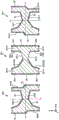
Fig. 6 is a schematic view showing a driving vibration mode of the physical quantity detecting vibration piece.
Fig. 7 is a schematic diagram showing a Y-axis detection vibration mode of the physical quantity detection vibration piece.
Fig. 8 is a schematic view showing a Z-axis detection vibration mode of the physical quantity detection vibration piece.
Fig. 9 is a perspective view of a physical quantity detecting vibration reed according to a second embodiment of the present invention.
Fig. 10 is a cross-sectional view taken along line C-C of fig. 9.
Fig. 11 is a cross-sectional view of a physical quantity detecting vibrating reed according to a third embodiment of the present invention.
Fig. 12 is a cross-sectional view of a physical quantity detecting vibrating reed according to a third embodiment of the present invention.
Fig. 13 is a cross-sectional view showing the direction of an electric field generated in the detection arm by bending vibration.
Fig. 14 is a cross-sectional view showing the direction of an electric field generated in the detection arm by bending vibration.
Fig. 15 is a top view and a bottom view of a physical quantity detecting vibration reed according to a fourth embodiment of the present invention.
Fig. 16 is a sectional view showing the center of gravity of the arm.
Fig. 17 is a top view and a bottom view showing a modification of the physical quantity detecting vibrating reed shown in fig. 15.
Fig. 18 is a top view and a bottom view showing a modification of the physical quantity detecting vibration reed shown in fig. 15.
Fig. 19 is a top view and a bottom view of a physical quantity detecting vibration reed according to a fifth embodiment of the present invention.
Fig. 20 is a block diagram showing a physical quantity detection device of the present invention.
Fig. 21 is a perspective view showing a configuration of a mobile (or notebook) personal computer to which an electronic apparatus according to the present invention is applied.
Fig. 22 is a perspective view showing the structure of a mobile phone (including PHS) to which the electronic device of the present invention is applied.
Fig. 23 is a perspective view showing a configuration of a digital camera to which an electronic apparatus of the present invention is applied.
Fig. 24 is a perspective view showing an automobile to which a mobile body of the present invention is applied.
Detailed Description
Hereinafter, the physical quantity detection resonator element, the physical quantity detection device, the electronic apparatus, and the moving object according to the present invention will be described in detail based on the embodiments shown in the drawings.
First embodiment
First, a physical quantity detecting vibration reed according to a first embodiment of the present invention will be described.
Fig. 1 is a perspective view of a physical quantity detecting vibration reed according to a first embodiment of the present invention. Fig. 2 is a sectional view taken along line a-a of fig. 1. Fig. 3 is a sectional view taken along line B-B of fig. 1. Fig. 4 and 5 are cross-sectional views each showing the direction of an electric field generated in the detection arm by bending vibration. Fig. 6 is a schematic view showing a driving vibration mode of the physical quantity detecting vibration piece. Fig. 7 is a schematic diagram showing a Y-axis detection vibration mode of the physical quantity detection vibration piece. Fig. 8 is a schematic view showing a Z-axis detection vibration mode of the physical quantity detection vibration piece. For convenience of explanation, the beam portion is not shown in the cross-sectional views of fig. 2 and 3.
Hereinafter, for convenience of explanation, the crystal axes of the crystal are referred to as an X-axis (electrical axis), a Y-axis (mechanical axis), and a Z-axis (optical axis), and a direction along the X-axis is also referred to as an "X-axis direction (second direction)", a direction along the Y-axis is also referred to as a "Y-axis direction (third direction)", and a direction along the Z-axis is also referred to as a "Z-axis direction (first direction)". The + Z axis side is also referred to as "upper", and the-Z axis side is also referred to as "lower".
The vibrating reed 1 shown in fig. 1 is a physical quantity detection vibrating reed capable of independently detecting an angular velocity ω Z around the Z axis and an angular velocity ω Y around the Y axis. The vibrating reed 1 includes a vibrator 2 and an electrode disposed on the vibrator 2.
The vibrator 2 is made of crystal. However, the material of the vibrator 2 is not limited to crystal, and for example, a piezoelectric material other than crystal such as lithium tantalate, lithium niobate, lithium borate, or barium titanate may be used. The vibrator 2 is formed in a plate shape having a width on an XY plane defined by X and Y axes which are crystal axes of the crystal and a thickness in the Z axis direction. That is, the vibrator 2 is formed by patterning a Z-cut quartz crystal plate. However, the cutting angle of the crystal is not limited thereto as long as the object can be achieved, and for example, the Z axis may be slightly shifted with respect to the thickness direction of the vibrator 2.
This vibrating body 2 has: a base 21 located at a substantially central portion; detection arms 221, 222 extending from the base 21 toward both sides in the Y-axis direction; connecting arms 231, 232 extending from the base 21 toward both sides in the X-axis direction; drive arms 241, 242 extending from the distal end portion of the connection arm 231 toward both sides in the Y axis direction; drive arms 243 and 244 extending from the distal end of the connection arm 232 toward both sides in the Y axis direction; support portions 251 and 252 disposed so as to be separated in the Y axis direction with the base portion 21 interposed therebetween; beam portions 261 and 262 connecting the base portion 21 and the support portion 251; beam portions 263 and 264 connecting the base portion 21 and the support portion 252. The support portions 251 and 252 are mounted on another member such as a package.
According to this configuration, since the arms 221, 222, 241, 242, 243, and 244 can be arranged in a well-balanced manner, the vibrator 2 can be vibrated in a well-balanced manner.
As shown in fig. 2, the detection arm 221 includes: a groove portion (detection arm first groove portion) 2211 that is open on the upper surface (detection arm first main surface) and extends in the Y-axis direction; a groove portion (detection arm second groove portion) 2212 that is open on the lower surface (detection arm second main surface) and extends in the Y-axis direction. Therefore, the detection arm 221 has an H-shaped cross-sectional shape. Further, the detection arm 221 includes: a protrusion (first protrusion) 2213 which is located between the groove portion 2211 and the side surface on the-X axis side (detection arm first side surface) and protrudes in the + Z axis direction; a protrusion (second protrusion) 2214 which is located between the groove portion 2212 and the side surface on the-X axis side and protrudes in the-Z axis direction; a protrusion (third protrusion) 2215 which is located between the groove portion 2211 and the + X-axis side surface (detection arm second side surface) and protrudes in the + Z-axis direction; a protrusion portion (fourth protrusion portion) 2216 which is located between the groove portion 2212 and the + X axis side face and protrudes in the-Z axis direction.
As shown in fig. 3, the detection arm 222 has: a groove portion (detection arm first groove portion) 2221 that is open on the upper surface (detection arm first main surface) and extends in the Y-axis direction; a groove portion (detection arm second groove portion) 2222 that is open on the lower surface (detection arm second main surface) and extends in the Y-axis direction. Thus, the detection arm 222 has an H-shaped cross-sectional shape. Further, the detection arm 222 has: a protrusion portion (first protrusion portion) 2223 that is located between the groove portion 2221 and a side surface on the-X axis side (detection arm first side surface), and protrudes in the + Z axis direction; a protrusion portion (second protrusion portion) 2224 located between the groove portion 2222 and the side surface on the-X axis side and protruding in the-Z axis direction; a protrusion portion (third protrusion portion) 2225 that is located between the groove portion 2221 and the + X-axis side surface (detection arm second side surface) and protrudes in the + Z-axis direction; a projection portion (fourth projection portion) 2226 which is located between the groove portion 2222 and the side surface on the + X axis side, and which projects in the-Z axis direction.
The detection arms 221 and 222 are provided on both sides of the base 21, and are arranged symmetrically with respect to an axis Jx passing through the center of gravity of the base 21 and along the X axis. With this arrangement, as will be described later, the angular velocity ω y and the angular velocity ω z can be independently detected by using the difference in the combination of the vibration directions of the detection arms 221 and 222.
As shown in fig. 2, the driving arm 241 has: a groove portion (drive arm first groove portion) 2411 that is open on the upper surface (drive arm first main surface) and extends in the Y-axis direction; a groove (drive arm second groove) 2412 that opens on the lower surface (drive arm second main surface) and extends in the Y-axis direction. Further, the driving arm 241 has: a step 2413 located on the-X axis side of the groove 2411 and connecting the upper surface and the-X axis side surface (drive arm first side surface); a step 2414 located on the + X axis side of the groove 2412 and connecting the lower surface and the + X axis side surface (drive arm second side surface).
As shown in fig. 3, the drive arm 242 includes: a groove portion (drive arm first groove portion) 2421 that is open on the upper surface (drive arm first main surface) and extends in the Y-axis direction; and a groove part (drive arm second groove part) 2422 that is open on the lower surface (drive arm second main surface) and extends in the Y-axis direction. Further, the drive arm 242 includes: a step part 2423 located on the-X axis side of the groove part 2421 and connecting a-X axis side surface (drive arm first side surface) of the upper surface; and a step part 2424 located on the + X axis side of the groove part 2422 and connecting the lower surface and the + X axis side surface (drive arm second side surface).
As shown in fig. 2, the driving arm 243 has: a groove portion (drive arm first groove portion) 2431 which is open on the upper surface (drive arm first main surface) and extends in the Y-axis direction; a groove portion (drive arm second groove portion) 2432 which is open on the lower surface (drive arm second main surface) and extends in the Y-axis direction. Further, the driving arm 243 includes: a step portion 2433 located on the + X axis side of the groove portion 2431 and connecting the upper surface and the + X axis side surface (drive arm first side surface); and a step portion 2434 located on the-X axis side of the groove portion 2432 and connecting the lower surface and the-X axis side surface (drive arm second side surface).
As shown in fig. 3, the driving arm 244 includes: a groove portion (drive arm first groove portion) 2441 that is open on the upper surface (drive arm first main surface) and extends in the Y-axis direction; a groove portion (drive arm second groove portion) 2442 which is open on the lower surface (drive arm second main surface) and extends in the Y-axis direction. Further, the driving arm 244 includes: a step portion 2443 located on the + X axis side of the groove portion 2441 and connecting the upper surface and the + X axis side surface (drive arm first side surface); and a step portion 2444 which is located on the-X axis side of the groove portion 2442 and connects the lower surface and the-X axis side surface (drive arm second side surface).
Of the drive arms 241 to 244, the drive arms 241 and 243 and the drive arms 242 and 244 are arranged symmetrically with respect to the axis Jx, and the drive arms 241 and 242 and the drive arms 243 and 244 are arranged symmetrically with respect to the axis Jy passing through the center of gravity and along the Y axis. The driving arms 241 to 244 have asymmetrical cross-sectional shapes with respect to two lines, i.e., a center line Lx of the arm in the X-axis direction and a center line Lz in the Z-axis direction. By adopting such a shape, as will be described later, in the driving vibration mode, the driving arms 241 to 244 can be vibrated in the oblique direction including the X-axis component and the Z-axis component.
The beam portion 261 passes between the detection arm 221 and the drive arm 241 to connect the base 21 and the support portion 251, and the beam portion 262 passes between the detection arm 221 and the drive arm 243 to connect the base 21 and the support portion 251. The beam portion 263 passes through between the detection arm 222 and the drive arm 242 to connect the base 21 and the support portion 252, and the beam portion 264 passes through between the detection arm 222 and the drive arm 244 to connect the base 21 and the support portion 252.
Next, the electrodes disposed on the vibrator 2 will be described. As shown in fig. 1 to 3, the vibrator 2 is provided with electrodes having: a driving signal electrode 31, a driving ground electrode 32, a first detection signal electrode 33, a second detection signal electrode 34, a first detection ground electrode 35, a third detection signal electrode 36, a fourth detection signal electrode 37, and a second detection ground electrode 38.
The drive signal electrodes 31 are disposed on the upper and lower surfaces of the drive arm 241 (in the grooves 2411 and 2412), the upper and lower surfaces of the drive arm 242 (in the grooves 2421 and 2422), both side surfaces of the drive arm 243, and both side surfaces of the drive arm 244. The drive signal electrode 31 is electrically connected to the drive signal terminal 41 disposed on the support portion 252 via the beam portion 264. The drive signal electrode 31 is an electrode for applying a drive signal (voltage) for causing the drive arms 241 to 244 to vibrate.
The drive ground electrode 32 is disposed on both side surfaces of the drive arm 241, both side surfaces of the drive arm 242, the upper and lower surfaces of the drive arm 243 (inside the groove portions 2431, 2432), and the upper and lower surfaces of the drive arm 244 (inside the groove portions 2441, 2442). The driving ground electrode 32 is electrically connected to the driving ground terminal 42 disposed on the support portion 251 via the beam portion 262. Such a driving ground electrode 32 is an electrode grounded (reference potential) with respect to the driving signal electrode 31.
The first detection signal electrode 33 is disposed on the-X-axis side surface of the groove portion 2211 and the-X-axis side surface of the groove portion 2212 of the detection arm 221. The first detection signal electrode 33 is electrically connected to the first detection signal terminal 43 disposed on the support portion 251 via the beam portion 261. Such a first detection signal electrode 33 is an electrode for taking a first detection signal S1 based on a coriolis force generated by applying an angular velocity. In addition, hereinafter, the first detection signal electrode 33 arranged at the groove portion 2211 is also referred to as "first electrode portion 331", and the first detection signal electrode 33 arranged at the groove portion 2212 is also referred to as "second electrode portion 332".
The second detection signal electrode 34 is disposed at the + X axis side surface of the detection arm 221. The second detection signal electrode 34 is electrically connected to the second detection signal terminal 44 disposed on the support portion 251 via the beam portion 261. Such a second detection signal electrode 34 is an electrode for taking a second detection signal S2 based on the coriolis force generated by applying the angular velocity. In addition, hereinafter, a portion arranged above the side surface of the second detection signal electrode 34 (the third projection 2215) will also be referred to as "the third electrode portion 341", and a portion arranged below the side surface (the fourth projection 2216) will also be referred to as "the fourth electrode portion 342". In the present embodiment, the electrode portions 341 and 342 are formed integrally, but the electrode portions 341 and 342 may be divided.
The first detection ground electrode 35 is disposed on the-X-axis side surface of the detection arm 221, the + X-axis side surface of the groove portion 2211, and the + X-axis side surface of the groove portion 2212. The first detection ground electrode 35 is electrically connected to the first detection ground terminal 45 disposed on the support portion 251 via the beam portion 262. The first detection ground electrode 35 is an electrode grounded (reference potential) to the first detection signal electrode 33 and the second detection signal electrode 34. In addition, hereinafter, a portion arranged above the side surface of the first detection ground electrode 35 (the first projection 2213) is also referred to as "the first ground electrode portion (the first reference potential electrode portion) 351", a portion arranged below the side surface (the second projection 2214) is also referred to as "the second ground electrode portion (the second reference potential electrode portion) 352", a portion arranged at the groove portion 2211 is also referred to as "the third ground electrode portion (the third reference potential electrode portion) 353", and a portion arranged at the groove portion 2212 is also referred to as "the fourth ground electrode portion (the fourth reference potential electrode portion) 354".
The first detection signal electrode 33, the second detection signal electrode 34, and the first detection ground electrode 35 disposed on the detection arm 221 have been described above. In summary of the above arrangement of the electrodes, the first electrode portion 331 and the first ground electrode portion 351 are arranged to face each other so as to sandwich the first projection 2213, the second electrode portion 332 and the second ground electrode portion 352 are arranged to face each other so as to sandwich the second projection 2214, the third electrode portion 341 and the third ground electrode portion 353 are arranged to face each other so as to sandwich the third projection 2215, and the fourth electrode portion 342 and the fourth ground electrode portion 354 are arranged to face each other so as to sandwich the fourth projection 2216. By adopting such a configuration, the electric field efficiency is improved, and a larger signal (voltage) can be extracted from the first detection signal electrode 33 and the second detection signal electrode 34.
As shown in fig. 4, when the detection arm 221 performs flexural vibration in the Z-axis direction (arrow a direction), the signal (electric field) Sz1 generated between the first electrode portion 331 and the first ground electrode portion 351 and the signal (electric field) Sz2 generated between the second electrode portion 332 and the second ground electrode portion 352 are in opposite phases, and the signal (electric field) Sz3 generated between the third electrode portion 341 and the third ground electrode portion 353 and the signal (electric field) Sz4 generated between the fourth electrode portion 342 and the fourth ground electrode portion 354 are in opposite phases. On the other hand, when the detecting arm 221 is subjected to flexural vibration in the X-axis direction (the direction of the arrow b), the signal Sx1 generated between the first electrode portion 331 and the first ground electrode portion 351 and the signal Sx2 generated between the second electrode portion 332 and the second ground electrode portion 352 are in phase, and the signal Sx3 generated between the third electrode portion 341 and the third ground electrode portion 353 and the signal Sx4 generated between the fourth electrode portion 342 and the fourth ground electrode portion 354 are in phase.
The third detection signal electrode 36 is disposed on the-X axis side surface of the groove portion 2221 and the-X axis side surface of the groove portion 2222 of the detection arm 222. The third detection signal electrode 36 is electrically connected to the third detection signal terminal 46 disposed on the support portion 252 via the beam portion 263. Such a third detection signal electrode 36 is an electrode for taking a third detection signal S3 based on the coriolis force generated by applying an angular velocity. In addition, hereinafter, the third detection signal electrode 36 arranged at the groove portion 2221 will also be referred to as "first electrode portion 361", and the third detection signal electrode 36 arranged at the groove portion 2222 will also be referred to as "second electrode portion 362".
The fourth detection signal electrode 37 is disposed on the + X axis side of the detection arm 222. The fourth detection signal electrode 37 is electrically connected to the fourth detection signal terminal 47 disposed at the supporting portion 252 via the beam portion 263. Such a fourth detection signal electrode 37 is an electrode for taking a fourth detection signal S4 based on the coriolis force generated by applying the angular velocity. In addition, hereinafter, a portion arranged above the side surface of the fourth detection signal electrode 37 (the third protruding portion 2225) will also be referred to as "the third electrode portion 371", and a portion arranged below the side surface (the fourth protruding portion 2226) will also be referred to as "the fourth electrode portion 372". In the present embodiment, the electrode portions 371 and 372 are formed integrally, but the electrode portions 371 and 372 may be divided.
The second detection ground electrode 38 is disposed on the-X-axis side surface of the detection arm 222, the + X-axis side surface of the groove 2221, and the + X-axis side surface of the groove 2222. The second detection ground electrode 38 is electrically connected to the second detection ground terminal 48 disposed on the support portion 252 via the beam portion 264. The second detection ground electrode 38 is an electrode grounded (reference potential) to the third detection signal electrode 36 and the fourth detection signal electrode 37. In addition, hereinafter, a portion arranged above the side surface of the second detection ground electrode 38 (the first projection 2223) will also be referred to as "first ground electrode portion (first reference potential electrode portion) 381", a portion arranged below the side surface (the second projection 2224) will also be referred to as "second ground electrode portion (second reference potential electrode portion) 382", a portion arranged at the groove portion 2221 will also be referred to as "third ground electrode portion (third reference potential electrode portion) 383", and a portion arranged at the groove portion 2222 will also be referred to as "fourth ground electrode portion (fourth reference potential electrode portion) 384".
The third detection signal electrode 36, the fourth detection signal electrode 37, and the second detection ground electrode 38 disposed on the detection arm 222 have been described above. In summary, the first electrode portion 361 and the first ground electrode portion 381 are arranged to face each other so as to sandwich the first projection 2223, the second electrode portion 362 and the second ground electrode portion 382 are arranged to face each other so as to sandwich the second projection 2224, the third electrode portion 371 and the third ground electrode portion 383 are arranged to face each other so as to sandwich the third projection 2225, and the fourth electrode portion 372 and the fourth ground electrode portion 384 are arranged to face each other so as to sandwich the fourth projection 2226. By adopting such a configuration, the electric field efficiency is improved, and a larger signal (voltage) can be extracted from the third detection signal electrode 36 and the fourth detection signal electrode 37.
In addition, as shown in fig. 5, when the detection arm 222 performs bending vibration in the Z-axis direction, the signal Sz1 generated between the first electrode portion 361 and the first ground electrode portion 381 and the signal Sz2 generated between the second electrode portion 362 and the second ground electrode portion 382 are in opposite phases, and the signal Sz3 generated between the third electrode portion 371 and the third ground electrode portion 383 and the signal Sz4 generated between the fourth electrode portion 372 and the fourth ground electrode portion 384 are in opposite phases. On the other hand, when the detecting arm 222 performs flexural vibration in the X-axis direction, the signal Sx1 generated between the first electrode portion 361 and the first ground electrode portion 381 and the signal Sx2 generated between the second electrode portion 362 and the second ground electrode portion 382 are in phase, and the signal Sx3 generated between the third electrode portion 371 and the third ground electrode portion 383 and the signal Sx4 generated between the fourth electrode portion 372 and the fourth ground electrode portion 384 are in phase.
The structure of the vibrating reed 1 is explained in detail above. Such a vibrating piece 1 can detect an angular velocity ω Y around the Y axis and an angular velocity ω Z around the Z axis in the following manner.
First, when a drive signal is applied between the drive signal electrode 31 and the drive ground electrode 32, the drive arms 241 to 244 vibrate in a drive vibration mode shown in fig. 6. Specifically, the driving arms 241 to 244 are each inclined and vibrated so as to include an X-axis component and a Z-axis component. This is because, when a drive signal is applied, the drive arms 241 to 244 are caused to perform flexural vibration in the X-axis direction by the inverse piezoelectric effect, but a vibration component in the Z-axis direction is generated by the cross-sectional shape (shape asymmetrical with respect to the center lines Lx and Lz) of the drive arms 241 to 244, and as a result, the drive arms are caused to perform vibration in an oblique direction so as to include an X-axis direction component and a Z-axis direction component.
In such a driving vibration mode, since the driving arms 241 and 242 and the driving arms 243 and 244 perform plane-symmetric bending vibration with respect to the YZ plane passing through the center of gravity, the vibration of the driving arms 241 to 244 in the X axis direction is cancelled. Therefore, the detection arms 221, 222 hardly vibrate in the X-axis direction. On the other hand, since the driving arms 241 to 244 vibrate toward the same side in the Z-axis direction, the vibrations of the driving arms 241 to 244 in the Z-axis direction are not cancelled out. Therefore, the detection arms 221 and 222 perform bending vibration along the Z-axis direction in a manner opposite to the driving arms 241 to 244 in order to balance the driving arms 241 to 244.
When the angular velocity ω Y around the Y axis is applied to the vibrating reed 1 in the state of driving in the driving vibration mode, the Y axis detection vibration mode shown in fig. 7 is excited again. In the Y-axis detection vibration mode, coriolis force acts on the drive arms 241 to 244, so that vibration in the direction indicated by arrow a is excited, and the detection arms 221 and 222 perform flexural vibration in the direction indicated by arrow B (along the X-axis direction) in response to the vibration. The electric charges generated in the detection arms 221 and 222 by the vibration are extracted from the detection signal electrodes 33, 34, 36, and 37 as detection signals S1, S2, S3, and S4, and the angular velocity ω y can be detected based on the signals.
On the other hand, when the angular velocity ω Z around the Z axis is applied to the vibrating reed 1 in the state of being driven in the driving vibration mode, the Z axis detection vibration mode shown in fig. 8 is excited again. In the Z-axis detection vibration mode, coriolis force acts on the drive arms 241 to 244, so that vibration in the direction indicated by arrow C is excited, and the detection arms 221 and 222 perform flexural vibration in the direction indicated by arrow D (along the X-axis direction) in response to the vibration. The electric charges generated in the detection arms 221 and 222 by the vibration are extracted from the detection signal electrodes 33, 34, 36, and 37 as detection signals S1, S2, S3, and S4, and the angular velocity ω z can be detected based on the signals.
Here, as shown in fig. 7, when the angular velocity ω y is applied, the detection arms 221 and 222 perform flexural vibration in the same phase in the X-axis direction. On the other hand, as shown in fig. 8, when the angular velocity ω z is applied, the detection arms 221 and 222 perform flexural vibration in opposite phases in the X-axis direction. The diaphragm 1 can independently detect the angular velocity ω y and the angular velocity ω z by using the difference in the combination of the vibration directions of the detection arms 221 and 222. This will be explained in detail below.
When the angular velocity ω y is applied to the vibrating reed 1, the detection arms 221 and 222 perform flexural vibration in the same phase in the X-axis direction as described above. As can be seen from fig. 4 and 5, the second detection signal S2 generated at this time is a signal having an inverse phase with respect to the first detection signal S1, the third detection signal S3 is in phase with the first detection signal S1, and the fourth detection signal S4 is in inverse phase with respect to the first detection signal S1. Therefore, if the intensities of the detection signals S1 to S4 are assumed to be equal, when the first detection signal S1 generated by applying the angular velocity ω y is assumed to be + Sy, the second detection signal S2 is-Sy, the third detection signal S3 is + Sy, and the fourth detection signal S4 is-Sy.
On the other hand, when the angular velocity ω z is applied to the vibrating reed 1, the detection arms 221 and 222 perform flexural vibration in opposite phases in the X-axis direction as described above. The second detection signal S2 generated at this time is a signal having an inverse phase of the first detection signal S1, the third detection signal S3 has an inverse phase of the first detection signal S1, and the fourth detection signal S4 has an in-phase with the first detection signal S1. Therefore, if it is assumed that the intensities of the detection signals S1 to S4 are equal, when the first detection signal S1 generated by applying the angular velocity ω z is set to + Sz, the second detection signal S2 is set to-Sz, the third detection signal S3 is set to-Sz, and the fourth detection signal S4 is set to + Sz.
Therefore, when the first detection signal S1 ═ Sy + Sz generated by applying the angular velocity ω yz around the axis having the two directional components of the Y axis direction and the Z axis direction (i.e., the axis inclined with respect to the two axes of the Y axis and the Z axis) to the vibrating reed 1, the second detection signal S2 ═ Sy-Sz, the third detection signal S3 ═ Sy-Sz, and the fourth detection signal S4 ═ Sy + Sz are assumed.
By adding or subtracting the detection signals S1, S2, S3, and S4 to each other, the angular velocity ω y and the angular velocity ω z can be separated from the angular velocity ω yz, and the angular velocity ω y and the angular velocity ω z can be independently detected.
Specifically, the detection arm 221 is calculated in (S1-S2) so that (+ Sy + Sz) - (-Sy-Sz) ═ 2(Sy + Sz) is multiplied, and the detection signal obtained from the detection arm 221 is multiplied. Similarly, the detection signal obtained from the detection arm 222 is multiplied by (+ Sy-Sz) - (-Sy + Sz) ═ 2(Sy-Sz) by performing the calculation (S3-S4) on the detection arm 222.
By performing the calculation of (S1-S2) + (S3-S4), 2(Sy + Sz) +2(Sy-Sz) ═ 4Sy can be obtained, and the signal Sy generated by the angular velocity ω y can be separated. Thereby, the angular velocity ω y is obtained. On the contrary, by performing the operations (S1-S2) - (S3-S4), 2(Sy + Sz) -2(Sy-Sz) becomes 4Sz, and the signal Sz generated by the angular velocity ω z can be separated. Thereby, the angular velocity ω z is obtained. As described above, according to the vibrating reed 1, the angular velocity ω y and the angular velocity ω z can be independently detected. In particular, since the signal obtained from the detection arm 221 is multiplied by the first detection signal S1 and the second detection signal S2, and the signal obtained from the detection arm 222 is multiplied by the third detection signal S3 and the fourth detection signal S4, the detection sensitivity of the angular velocity ω y and the angular velocity ω z is improved.
According to the vibrating reed 1, the following effects can be exhibited in addition to the above-described effects. In the vibrating reed 1, since the drive signal electrode 31 (the drive signal terminal 41, the conductor to which the drive signal is applied such as a wire) is disposed so as to be close to the detection signal electrodes 33, 34, 36, and 37, noise generated in the drive signal is mixed into the detection signals S1, S2, S3, and S4 due to electrostatic coupling between the drive signal electrode 31 and the detection signal electrodes 33, 34, 36, and 37. Such noise may incur a decrease in detection sensitivity. However, according to the vibrating reed 1, the noise mixed in the detection signals S1, S2, S3, and S4 can be sufficiently eliminated (reduced), and the angular velocity can be detected with high accuracy.
Hereinafter, a specific description will be given by taking, as an example, a case where the capacitance C1 between the drive signal electrode 31 and the first detection signal electrode 33 is 1.7[ fF ], the capacitance C2 between the drive signal electrode 31 and the second detection signal electrode 34 is 0.9[ fF ], the capacitance C3 between the drive signal electrode 31 and the third detection signal electrode 36 is 1.8[ fF ], and the capacitance C4 between the drive signal electrode 31 and the fourth detection signal electrode 37 is 1.1[ fF ]. The capacitances C1 to C4 are different from each other in the relative positional relationship between the detection signal electrodes 33, 34, 36, and 37 and the drive signal electrode 31. Specifically, since the drive signal electrode 31 is drawn out to the support portion 252 via the beam portion 264, the capacitances C3 and C4 close to the beam portion 264 are slightly larger than the capacitances C1 and C2 distant from the beam portion 264. For convenience of explanation, the capacitance C1 is considered to be proportional to noise mixed in the first detection signal S1, the capacitance C2 is considered to be proportional to noise mixed in the second detection signal S2, the capacitance C3 is considered to be proportional to noise mixed in the third detection signal S3, and the capacitance C4 is considered to be proportional to noise mixed in the fourth detection signal S4.
As described above, in the vibrating reed 1, the calculation of (S1-S2) + (S3-S4) is performed to obtain the angular velocity ω y. At this time, since addition and subtraction are also performed together with noise, the noise included in the calculation result of (S1-S2) + (S3-S4) is proportional to (1.7-0.9) + (1.8-1.1) ═ 1.5[ fF ]. In this case, although the noise on the detection arm 221 side is added to the noise on the detection arm 222 side, since a part of the noise is cancelled in the detection arm 221 and a part of the noise is also cancelled in the detection arm 222, the increase in the noise as a whole is suppressed. Therefore, the angular velocity ω y can be detected with further high accuracy.
As described above, in the vibrating reed 1, the calculations corresponding to (S1-S2) - (S3-S4) are performed to obtain the angular velocity ω z. At this time, since addition and subtraction are also performed together with noise, the noise included in the calculation results of (S1-S2) - (S3-S4) is proportional to (1.7-0.9) - (1.8-1.1) ═ 0.1[ fF ]. In this case, since a part of the noise is cancelled in the detection arm 221, a part of the noise is cancelled in the detection arm 222, and the remaining noises cancel each other, the noise as a whole is suppressed to be sufficiently low. Therefore, the angular velocity ω z can be detected with further high accuracy.
Thus, the oscillator can effectively reduce noise, and can detect both the angular velocity ω y and the angular velocity ω z with high sensitivity.
Further, according to the vibrating reed 1, it is possible to reduce the leakage signal (output) from the detection arms 221 and 222 in the driving vibration mode. Therefore, erroneous detection of the angular velocity ω z and the angular velocity ω y can be reduced.
Specifically, as described above, since the detection arms 221 and 222 vibrate in the Z-axis direction when the vibration mode is driven, electric charges are generated in the detection arms 221 and 222 even in a state where an angular velocity is not applied. However, as is clear from fig. 4, the signal obtained from the first electrode portion 331 and the signal obtained from the second electrode portion 332 are in opposite phases, and therefore, the leakage signal is canceled in the first detection signal electrode 33, and the signal obtained from the third electrode portion 341 and the signal obtained from the fourth electrode portion 342 are in opposite phases, and therefore, the leakage signal is canceled in the second detection signal electrode 34. Therefore, the leak signal from the detection arm 221 can be reduced. Similarly, as is apparent from fig. 5, the signal obtained from the first electrode portion 361 and the signal obtained from the second electrode portion 362 are in opposite phase, and therefore, the leakage signal is canceled in the third detection signal electrode 36, and the signal obtained from the third electrode portion 371 and the signal obtained from the fourth electrode portion 372 are in opposite phase, and therefore, the leakage signal is canceled in the fourth detection signal electrode 37. Therefore, the leak signal from the detection arm 222 can be reduced.
Second embodiment
Fig. 9 is a perspective view of a physical quantity detecting vibration reed according to a second embodiment of the present invention. Fig. 10 is a cross-sectional view taken along line C-C of fig. 9.
Hereinafter, differences between the physical quantity detecting vibration reed of the second embodiment and the above-described embodiments will be mainly described, and descriptions of the same matters will be omitted.
The physical quantity detection vibration member of the second embodiment is the same as the physical quantity detection vibration member of the first embodiment except that the electrodes are mainly drawn out differently. In fig. 9 and 10, the same components as those of the above-described embodiment are denoted by the same reference numerals.
As shown in fig. 9, in the vibrating reed 1 of the present embodiment, the driving signal electrode 31 is electrically connected to the driving signal terminal 411 disposed on the support portion 251 by the beam portion 262, and the driving signal electrode 31 is electrically connected to the driving signal terminal 412 disposed on the support portion 252 by the beam portion 264. On the other hand, the driving ground electrode 32 is electrically connected to the driving ground terminal 421 disposed on the support portion 251 by the beam portion 262, and the driving ground electrode 32 is electrically connected to the driving ground terminal 422 disposed on the support portion 252 by the beam portion 264. As shown in fig. 10, the beam portions 262 and 264 are divided into upper and lower sides of the side surface, and a wiring 310 for driving the signal electrode 31 and a wiring 320 for driving the ground electrode 32 are arranged.
By adopting such an arrangement, the wiring 310 and the drive signal terminals 411 and 412 can be arranged symmetrically with respect to the axis Jx. Therefore, the difference between the capacitance C1 and the capacitance C3 and the difference between the capacitance C2 and the capacitance C4 described in the first embodiment can be eliminated (closer to 0). This can further effectively reduce noise generated by the difference between the capacitances C1 to C4.
According to the second embodiment, the same effects as those of the first embodiment can be obtained.
Third embodiment
Fig. 11 and 12 are cross-sectional views of a physical quantity detecting vibrating reed according to a third embodiment of the present invention. Fig. 13 and 14 are cross-sectional views each showing the direction of an electric field generated in the detection arm by bending vibration.
Hereinafter, differences between the physical quantity detecting vibration reed of the third embodiment and the above-described embodiments will be mainly described, and descriptions of the same items will be omitted.
The physical quantity detection vibration reed of the third embodiment is the same as the physical quantity detection vibration reed of the first embodiment except that the structure of the electrodes is mainly different. In fig. 11 to 14, the same components as those of the above-described embodiment are denoted by the same reference numerals. Fig. 11 corresponds to fig. 2, and fig. 12 corresponds to fig. 3.
As shown in fig. 11 and 12, in the vibrating reed 1 of the present embodiment, the electrode includes: a driving signal electrode 31, a driving ground electrode 32, a first detection signal electrode 33, a second detection signal electrode 34, a third detection signal electrode 36, and a fourth detection signal electrode 37. That is, the first detection ground electrode 35 and the second detection ground electrode 38 are omitted from the first embodiment. Since the arrangement of the drive signal electrode 31 and the drive ground electrode 32 is the same as that of the first embodiment, the arrangement of the detection signal electrodes 33, 34, 36, and 37 will be described below.
The first detection signal electrode 33 is disposed on the inner surface of the groove 2211, 2212 of the detection arm 221. On the other hand, the second detection signal electrodes 34 are disposed on both side surfaces of the detection arm 221. In addition, hereinafter, for convenience of explanation, the first detection signal electrode 33 disposed at the groove portion 2211 is also referred to as "first electrode portion 333", and the first detection signal electrode 33 disposed at the groove portion 2212 is also referred to as "second electrode portion 334". The second detection signal electrode 34 disposed on the side surface on the-X axis side is also referred to as a "third electrode portion 343", and the second detection signal electrode 34 disposed on the side surface on the + X axis side is also referred to as a "fourth electrode portion 344".
In summary, the arrangement of the electrodes is such that the first electrode portion 333 and the third electrode portion 343 are arranged to face each other with the first projection 2213 interposed therebetween, the second electrode portion 334 and the third electrode portion 343 are arranged to face each other with the second projection 2214 interposed therebetween, the first electrode portion 333 and the fourth electrode portion 344 are arranged to face each other with the third projection 2215 interposed therebetween, and the second electrode portion 334 and the fourth electrode portion 344 are arranged to face each other with the fourth projection 2216 interposed therebetween. By adopting such a configuration, the electric field efficiency is improved, and a larger signal (voltage) can be extracted from the first detection signal electrode 33 and the second detection signal electrode 34.
In addition, as shown in fig. 13, when the detection arm 221 performs bending vibration in the Z-axis direction, the signal Sz1 generated between the first electrode portion 333 and the third electrode portion 343 and the signal Sz2 generated between the second electrode portion 334 and the third electrode portion 343 are in opposite phases, and the signal Sz3 generated between the first electrode portion 333 and the fourth electrode portion 344 and the signal Sz4 generated between the second electrode portion 334 and the fourth electrode portion 344 are in opposite phases. On the other hand, when the detecting arm 221 performs flexural vibration in the X-axis direction, the signal Sx1 generated between the first electrode portion 333 and the third electrode portion 343 and the signal Sx2 generated between the second electrode portion 334 and the third electrode portion 343 are in phase, and the signal Sx3 generated between the first electrode portion 333 and the fourth electrode portion 344 and the signal Sx4 generated between the second electrode portion 334 and the fourth electrode portion 344 are in phase.
The third detection signal electrode 36 is disposed on the inner surface of the groove portions 2221, 2222 of the detection arm 222. On the other hand, the fourth detection signal electrodes 37 are disposed on both side surfaces of the detection arm 222. In addition, hereinafter, for convenience of explanation, the third detection signal electrode 36 arranged at the groove portion 2221 will also be referred to as "first electrode portion 363", and the third detection signal electrode 36 arranged at the groove portion 2222 will also be referred to as "second electrode portion 364". The fourth detection signal electrode 37 disposed on the side surface on the-X axis side is also referred to as a "third electrode portion 373", and the fourth detection signal electrode 37 disposed on the side surface on the + X axis side is also referred to as a "fourth electrode portion 374".
In summary of the above-described electrode arrangement, the first electrode portion 363 and the third electrode portion 373 are arranged to face each other so as to sandwich the first projection 2223, the second electrode portion 364 and the third electrode portion 373 are arranged to face each other so as to sandwich the second projection 2224, the first electrode portion 363 and the fourth electrode portion 374 are arranged to face each other so as to sandwich the third projection 2225, and the second electrode portion 364 and the fourth electrode portion 374 are arranged to face each other so as to sandwich the fourth projection 2226. By adopting such a configuration, the electric field efficiency is improved, and a larger signal (voltage) can be extracted from the third detection signal electrode 36 and the fourth detection signal electrode 37.
In addition, as shown in fig. 14, when the detection arm 222 performs flexural vibration in the Z-axis direction, the signal Sz1 generated between the first electrode portion 363 and the third electrode portion 373 and the signal Sz2 generated between the second electrode portion 364 and the third electrode portion 373 are in opposite phases, and the signal Sz3 generated between the first electrode portion 363 and the fourth electrode portion 374 and the signal Sz4 generated between the second electrode portion 364 and the fourth electrode portion 374 are in opposite phases. On the other hand, when the detection arm 222 performs flexural vibration in the X-axis direction, the signal Sx1 generated between the first electrode portion 363 and the third electrode portion 373 and the signal Sx2 generated between the second electrode portion 364 and the third electrode portion 373 are in phase, and the signal Sx3 generated between the first electrode portion 363 and the fourth electrode portion 374 and the signal Sx4 generated between the second electrode portion 364 and the fourth electrode portion 374 are in phase.
With such a configuration, the angular velocity ω y and the angular velocity ω z can be independently detected by calculating the detection signals S1, S2, S3, and S4 as in the first embodiment. Further, as in the first embodiment, the signal obtained from the detection arm 221 can be multiplied by the first detection signal S1 and the second detection signal S2, and the signal obtained from the detection arm 222 can be multiplied by the third detection signal S3 and the fourth detection signal S4. Further, as in the first embodiment, the capacitance (noise) generated between the driving signal electrodes 31 can be eliminated. In addition, as in the first embodiment, the leakage signal in the driving vibration mode can be eliminated in each of the detection signal electrodes 33, 34, 36, and 37.
According to the third embodiment, the same effects as those of the first embodiment can be obtained.
Fourth embodiment
Fig. 15 is a top view and a bottom view of a physical quantity detecting vibration reed according to a fourth embodiment of the present invention. Fig. 16 is a sectional view showing the center of gravity of the arm. Fig. 17 and 18 are a top view and a bottom view respectively showing a modification of the physical quantity detection vibrating reed shown in fig. 15. In fig. 15, 17, and 18, for convenience of explanation, the electrodes, the wires, the terminals, the grooves, and the step portions are not shown.
Hereinafter, differences between the physical quantity detecting vibration reed of the fourth embodiment and the above-described embodiments will be mainly described, and descriptions of the same matters will be omitted.
The physical quantity detecting vibration member of the fourth embodiment is the same as the physical quantity detecting vibration member of the first embodiment described above, except that it mainly has a weight portion. In fig. 15 to 18, the same components as those of the above-described embodiment are denoted by the same reference numerals.
In the vibrating reed 1 of the present embodiment, the wide portions (hammers) 2210, 2220 having a wider width are provided at the distal end portions of the detection arms 221, 222, and the wide portions (hammers) 2410, 2420, 2430, 2440 having a wider width are provided at the distal end portions of the driving arms 241, 242, 243, 244. Although the wide width portion is also provided in the first embodiment, the description of the wide width portion is not particularly limited to the first embodiment.
Further, the wide parts 2210, 2220 are provided with a weight 51 for adjusting the resonance frequency of the detection vibration mode, and the wide parts 2410, 2420, 2430, 2440 are provided with a weight 52 for adjusting the resonance frequency of the drive vibration mode. For example, the resonance frequency or the vibration balance of the detection vibration mode can be adjusted by removing a part of the weight 51 by laser irradiation or the like and changing the mass of the detection arms 221 and 222, and similarly, the resonance frequency or the vibration balance of the driving vibration mode can be adjusted by removing a part of the weight 52 by laser irradiation or the like and changing the mass of the driving arms 241, 242, 243, and 244. The weight portions 51 and 52 may be formed of, for example, a metal film.
Here, among the three arms 221, 241, 243 of the six arms 221, 222, 241, 242, 243, 244 located on the + Y axis side with respect to the axis Jx, the weights (first weights) 51, 52 are provided on the upper surfaces (one surface) of the wide width portions 2210, 2410, 2430, and among the three arms 222, 242, 244 located on the-Y axis side with respect to the axis Jx, the weights (second weights) 51, 52 are provided on the lower surfaces (the other surface) of the wide width portions 2220, 2420, 2440. Therefore, as shown in fig. 16, the center of gravity Ga of the arm including the electrode and the weight portion is shifted to the + Z axis side from the axis (center line Lx) of the arm among the arms 221, 241, 243, and the center of gravity Gb of the arm including the electrode and the weight portion is shifted to the-Z axis side from the axis (center line Lx) of the arm among the arms 222, 242, 244. By disposing the weight portions 51 and 52 in this manner, the symmetry of the vibrating reed 1 with respect to the XY plane is improved, and the lateral sensitivity can be reduced. Therefore, the detection sensitivity of the angular velocity is improved.
According to the fourth embodiment, the same effects as those of the first embodiment can be obtained.
As a modification of the present embodiment, for example, as shown in fig. 17, the detection arms 221 and 222 may have a configuration in which the weight 51 is disposed in reverse to the present embodiment. That is, the weight 51 is disposed on the lower surface of the wide part 2210 and the upper surface of the wide part 2220.
As another modification, for example, as shown in fig. 18, the weight portions 51 may be disposed on the upper and lower surfaces of the wide portions 2210, 2220, and the weight portions 52 may be disposed on the upper and lower surfaces of the wide portions 2410, 2420, 2430, 2440. This enables the center of gravity of the arms 221, 222, 241, 242, 243, and 244 including the electrodes and the weights to be aligned with the axis (center line Lx) of the arms. Therefore, the symmetry of the vibrating reed 1 with respect to the XY plane is improved, and the lateral sensitivity can be reduced.
Fifth embodiment
Fig. 19 is a top view and a bottom view of a physical quantity detecting vibration reed according to a fifth embodiment of the present invention.
Hereinafter, differences between the physical quantity detecting vibration reed of the fifth embodiment and the above-described embodiments will be mainly described, and descriptions of the same items will be omitted.
The physical quantity detecting vibration reed of the fifth embodiment is the same as the physical quantity detecting vibration reed of the first embodiment except that the physical quantity detecting vibration reed mainly has a different structure of the driving arm. In fig. 19, the same components as those of the above-described embodiment are denoted by the same reference numerals.
As shown in fig. 19, in the driving arm 241 of the present embodiment, the distal ends of the step portions 2413 and 2414 are positioned closer to the distal end of the driving arm 241 than the distal ends of the groove portions 2411 and 2412. Although not shown, the same applies to the other drive arms 242, 243, and 244. With this configuration, the asymmetric portions of the drive arms 241, 242, 243, and 244 are further lengthened, and therefore the drive arms 241 to 244 can be more smoothly tilted in the drive vibration mode. When the length of the grooves 2411 and 2412 is L1 and the length of the steps 2413 and 2414 is L2, L1 and L2 preferably satisfy the relationship of L1 < L2 ≦ 1.5L 1.
In the fifth embodiment, the same effects as those of the first embodiment can be obtained.
Physical quantity detecting device
Next, a physical quantity detecting device including the physical quantity detecting vibrating reed of the present invention will be described. Fig. 20 is a block diagram showing a physical quantity detection device of the present invention.
As shown in fig. 20, the physical quantity detection device 10 includes: a vibrating piece 1; a drive circuit 9 for driving the vibrating piece 1 to vibrate; a detection circuit 6 for detecting the detected vibration of the vibrating piece 1 when an angular velocity is applied. The drive circuit 9 and the detection circuit 6 may be realized by a single IC chip, or may be realized by separate IC chips.
The drive circuit 9 includes an I/V conversion circuit (current-voltage conversion circuit) 91, an AC amplification circuit 92, and an amplitude adjustment circuit 93. The drive circuit 9 outputs a signal for driving the drive arms 241 to 244 to the drive signal electrode 31 of the vibrating reed 1, and inputs a signal output from the drive ground electrode 32 of the vibrating reed 1.
When the driving arms 241 to 244 of the vibrating reed 1 vibrate, an alternating current based on the piezoelectric effect is output from the driving ground electrode 32 and is input to the I/V conversion circuit 91. The I/V conversion circuit 91 converts the input ac current into an ac voltage signal having the same frequency as the vibration frequency of the drive arms 241 to 244 and outputs the ac voltage signal. The alternating voltage signal output from the I/V conversion circuit 91 is input to the AC amplification circuit 92. The AC amplifier circuit 92 amplifies the input AC voltage signal and outputs the amplified signal.
The AC voltage signal output from the AC amplification circuit 92 is input to the amplitude adjustment circuit 93. The amplitude adjustment circuit 93 controls the gain so as to maintain the amplitude of the input ac voltage signal at a stable value, and outputs the gain-controlled ac voltage signal to the drive signal electrode 31 of the vibrating reed 1. The driving arms 241 to 244 vibrate in a driving vibration mode by an alternating voltage signal (driving signal) input to the driving signal electrode 31.
The detection circuit 6 includes: charge amplifiers 61, 62, 63, 64, subtraction processing circuits 65, 66, a Y-axis angular velocity detection unit 7, and a Z-axis angular velocity detection unit 8. The detection circuit 6 is a circuit for detecting the angular velocity ω y and the angular velocity ω z based on signals output from the detection signal electrodes 33, 34, 36, and 37 of the vibrating reed 1, respectively.
The charge amplifier 61 (first current/voltage conversion unit) includes an operational amplifier, a feedback resistor, and a feedback capacitor, and a detection signal Sb output from the second detection signal electrode 34 of the detection arm 221 (a detection signal output from the third electrode portion 341 and a detection signal output from the fourth electrode portion 342) is input to an inverting input terminal (-terminal) of the operational amplifier, and a non-inverting input terminal (+ terminal) of the operational amplifier is fixed to a reference potential. The charge amplifier 61 converts the detection signal input to the operational amplifier into an alternating voltage signal.
The charge amplifier 62 (second current-voltage conversion unit) includes an operational amplifier, a feedback resistor, and a feedback capacitor, and has an inverting input terminal (-terminal) to which a detection signal Sa output from the first detection signal electrode 33 of the detection arm 221 (a detection signal output from the first electrode unit 331 and a detection signal output from the second electrode unit 332) is input, and a non-inverting input terminal (+ terminal) of the operational amplifier is fixed to a reference potential. The charge amplifier 62 converts the detection signal input to the operational amplifier into an alternating voltage signal.
In addition, the electrical characteristics of the detection signal Sa and the detection signal Sb are opposite.
The output signal of the charge amplifier 61 and the output signal of the charge amplifier 62 are input to a subtraction processing circuit (differential amplification circuit) 65. The subtraction processing circuit 65 functions as a differential amplifier unit that differentially amplifies the output signal of the vibrating reed 1, and outputs a signal obtained by amplifying (differentially amplifying) the potential difference between the output signal of the charge amplifier 61 and the output signal of the charge amplifier 62. The output signal S' of the subtraction processing circuit 65 is input to the Y-axis angular velocity detection unit 7 and the Z-axis angular velocity detection unit 8.
The charge amplifier 63 (third current-voltage conversion unit) includes an operational amplifier, a feedback resistor, and a feedback capacitor, and has an inverting input terminal (-terminal) to which a detection signal Sc output from the third detection signal electrode 36 of the detection arm 222 (a detection signal output from the first electrode unit 361 and a detection signal output from the second electrode unit 362) is input, and a non-inverting input terminal (+ terminal) of the operational amplifier is fixed to a reference potential. The charge amplifier 63 converts the detection signal input to the operational amplifier into an alternating voltage signal.
The charge amplifier 64 (fourth current-voltage conversion section) is configured to include an operational amplifier, a feedback resistor, and a feedback capacitor, and a detection signal (a detection signal output from the third electrode section 371 and a detection signal output from the fourth electrode section 372) Sd output from the fourth detection signal electrode 37 of the detection arm 222 is input to an inverting input terminal (-terminal) of the operational amplifier, and a non-inverting input terminal (+ terminal) of the operational amplifier is fixed to a reference potential. The charge amplifier 64 converts the detection signal input to the operational amplifier into an alternating voltage signal.
In addition, the electrical characteristics of the detection signal Sc and the detection signal Sd are opposite.
The output signal of the charge amplifier 63 and the output signal of the charge amplifier 64 are input to a subtraction processing circuit (differential amplification circuit) 66. The subtraction processing circuit 66 functions as a differential amplifier unit that differentially amplifies the output signal of the vibrating reed 1, and outputs a signal obtained by amplifying (differentially amplifying) the potential difference between the output signal of the charge amplifier 63 and the output signal of the charge amplifier 64. The output signal S ″ of the subtraction processing circuit 66 is input to the Y-axis angular velocity detection unit 7 and the Z-axis angular velocity detection unit 8.
The Y-axis angular velocity detection unit 7 includes: an addition processing circuit 71, an AC amplification circuit 72, a synchronous detection circuit 73, a smoothing circuit 74, a variable amplification circuit 75, and a filter circuit 76.
The output signal S' of the subtraction processing circuit 65 and the output signal S ″ of the subtraction processing circuit 66 are input to the addition processing circuit 71. The addition processing circuit 71 functions as an addition amplifier for adding and amplifying the output signals of the vibrating reed 1, adds the potentials of the output signal S' of the subtraction processing circuit 65 and the output signal S ″ of the subtraction processing circuit 66, and outputs the amplified signals. The output signal of the addition processing circuit 71 is input to an AC amplification circuit 72.
The AC amplification circuit 72 functions as an AC amplification unit that amplifies an AC signal, and outputs a signal obtained by amplifying the output signal of the addition processing circuit 71. The output signal of the AC amplification circuit 72 is input to the synchronous detection circuit 73. The synchronous detection circuit 73 performs synchronous detection on the output signal of the AC amplification circuit 72 based on the alternating voltage signal output from the AC amplification circuit 92 of the drive circuit 9, thereby extracting an angular velocity component around the Y axis.
The signal of the angular velocity component around the Y axis extracted by the synchronous detector circuit 73 is smoothed into a dc voltage signal by the smoothing circuit 74, and is input to the variable amplifier circuit 75. The variable amplification circuit 75 amplifies (or attenuates) the output signal (dc voltage signal) of the smoothing circuit 74 at a set amplification factor (or attenuation factor) to change the angular velocity sensitivity. The signal amplified (or attenuated) by the variable amplification circuit 75 is input to the filter circuit 76.
The filter circuit 76 attenuates noise components of high frequencies outside the sensor band (to be precise, to a predetermined level or less) from the output signal of the variable amplifier circuit 75, and outputs a detection signal of a polarity and a voltage level corresponding to the direction and magnitude of the angular velocity around the Y axis. The detection signal is output to the outside from an external output terminal (not shown).
The Z-axis angular velocity detection unit 8 includes: a subtraction circuit 81, an AC amplifier circuit 82, a synchronous detector circuit 83, a smoothing circuit 84, a variable amplifier circuit 85, and a filter circuit 86.
The output signal S' of the subtraction processing circuit 65 and the output signal S ″ of the subtraction processing circuit 66 are input to the subtraction processing circuit 81. The subtraction processing circuit 81 functions as a differential amplifier that differentially amplifies the output signal of the vibrating reed 1, and outputs a signal obtained by amplifying (differentially amplifying) the potential difference between the output signal S' of the subtraction processing circuit 65 and the output signal S ″ of the subtraction processing circuit 66. The output signal of the subtraction processing circuit 81 is input to the AC amplification circuit 82.
The AC amplification circuit 82 functions as an AC amplification unit that amplifies an AC signal, and outputs a signal obtained by amplifying the output signal of the subtraction processing circuit 81. The output signal of the AC amplification circuit 82 is input to the synchronous detection circuit 83. The synchronous detection circuit 83 extracts an angular velocity component around the Z axis by synchronously detecting the output signal of the AC amplification circuit 82 based on the alternating voltage signal output from the AC amplification circuit 92 of the drive circuit 9.
The signal of the angular velocity component around the Z axis extracted by the synchronous detector circuit 83 is smoothed into a dc voltage signal by the smoothing circuit 84, and is input to the variable amplifier circuit 85. The variable amplification circuit 85 amplifies (or attenuates) the output signal (dc voltage signal) of the smoothing circuit 84 at a set amplification factor (or attenuation factor) to change the angular velocity sensitivity. The signal amplified (or attenuated) by the variable amplification circuit 85 is input to the filter circuit 86.
The filter circuit 86 attenuates noise components of high frequencies outside the sensor band (to be precise, to a predetermined level or less) from the output signal of the variable amplifier circuit 85, and outputs a detection signal of a polarity and a voltage level corresponding to the direction and magnitude of the angular velocity around the Z axis. The detection signal is output to the outside from an external output terminal (not shown).
Electronic device
Next, an electronic device including the physical quantity detecting vibrating reed of the present invention will be described.
Fig. 21 is a perspective view showing a configuration of a mobile (or notebook) personal computer to which an electronic apparatus according to the present invention is applied.
In the figure, the personal computer 1100 includes a main body portion 1104 having a keyboard 1102 and a display unit 1106 having a display portion 1108, and the display unit 1106 is supported so as to be rotatable with respect to the main body portion 1104 via a hinge structure portion. The personal computer 1100 includes the vibrating reed 1.
Fig. 22 is a perspective view showing the structure of a mobile phone (including PHS) to which the electronic device of the present invention is applied.
In this figure, the mobile phone 1200 includes an antenna (not shown), a plurality of operation buttons 1202, a handset 1204, and a microphone 1206, and a display unit 1208 is disposed between the operation buttons 1202 and the handset 1204. The vibrating piece 1 is incorporated in the mobile phone 1200.
Fig. 23 is a perspective view showing a configuration of a digital camera to which an electronic apparatus of the present invention is applied.
A display portion 1310 is provided on the back surface of a case (main body) 1302 of the digital camera 1300, and is configured to perform display based on the image pickup signal generated by the CCD, and the display portion 1310 functions as a viewfinder for displaying an object as an electronic image. A light receiving unit 1304 including an optical lens (imaging optical system) or a CCD is provided on the front surface side (back surface side in the figure) of the housing 1302. When the photographer checks the subject image displayed on the display unit 1310 and presses the shutter button 1306, the image pickup signal of the CCD at that point in time is transferred to and stored in the memory 1308. In such a digital camera 1300, for example, a vibrating reed 1 for shake correction is built in. Since the electronic apparatus includes the vibrating reed 1, it has excellent reliability.
The electronic device of the present invention can be applied to, for example, a wearable terminal such as a smartphone, a tablet terminal, a clock (including a smartwatch), an inkjet ejection device (for example, an inkjet printer), a laptop personal computer, a television, or an HMD (head mounted display), a camera, a video camera, a car navigation device, a pager, an electronic organizer (including a product with a communication function), an electronic dictionary, a desktop electronic calculator, an electronic game device, a word processor, a workstation, a video telephone, a video monitor for theft prevention, an electronic binocular, a POS (Point of Sale) terminal, a medical device (for example, an electronic thermometer, a sphygmomanometer, a blood glucose meter, an electrocardiograph measurement device, an ultrasonic diagnostic device, in addition to the personal computer of fig. 21, the cellular phone of fig. 22, and the digital camera of fig. 23, Electronic endoscopes), fish finder, various measuring devices, metrology instruments (e.g., of vehicles, aircraft, ships), flight simulators, and the like.
Moving body
Next, a moving object including the physical quantity detection vibrating reed of the present invention will be described.
Fig. 24 is a perspective view showing an automobile to which a mobile body of the present invention is applied. As shown in fig. 24, the automobile 1500 incorporates the vibrating reed 1, and the posture of the vehicle body 1501 can be detected by the vibrating reed 1, for example. A detection signal of the vibrating reed 1 is supplied to a vehicle body attitude control device 1502, and the vehicle body attitude control device 1502 can detect the attitude of the vehicle body 1501 based on the signal, and control the hardness of the suspension or the brake of each wheel 1503 based on the detection result. In addition to this, such attitude control can also be utilized in bipedal walking robots or radio controlled helicopters (including unmanned planes). As described above, the vibrating piece 1 is mounted in realizing the attitude control of various moving bodies.
The physical quantity detection vibrating reed, the physical quantity detection device, the electronic apparatus, and the moving object of the present invention have been described above based on the illustrated embodiments, but the present invention is not limited thereto, and the configurations of the respective portions may be replaced with arbitrary configurations having the same function. In the present invention, other arbitrary structures may be added.
In the above-described embodiment, the physical quantity detection vibrating reed includes the support portion and the beam portion that support the base, but the support portion and the beam portion may be omitted. In this case, each terminal may be disposed on the base.
Description of the symbols
1 … vibrating reed; 10 … physical quantity detecting means; 2 … vibrating body; 21 … a base; 221 … detection arm; 2210 … broad width portions; 2211. 2212 … slot; 2213 … first tab; 2214 … second tab; 2215 … third tab; 2216 … fourth tab; 222 … detection arm; 2220 … wide width part; 2221. 2222 … slot parts; 2223 … first projection; 2224 … second projection; 2225 … third projection; 2226 … fourth projection; 231. 232 … connecting arms; 241 … drive the arm; 2410 … wide part; 2411. 2412 … groove part; 2413. 2414 … step portion; 242 … drive arm; 2420 … broad width part; 2421. 2422 … groove part; 2423. 2424 … step; 243 … drive the arm; 2430 … wide part; 2431. 2432 … groove part; 2433. 2434 … wide part; 244 … drive the arm; 2440 … wide part; 2441. 2442 … groove part; 2443. 2444 … step; 251. 252 … support portion; 261. 262, 263, 264 … beam portion; 31 … drive signal electrodes; 310 … wiring; 32 … drive the ground electrode; 320 … wiring; 33 … a first detection signal electrode; 331 … first electrode portion; 332 … second electrode portion; 333 … first electrode portion; 334 … second electrode portion; 34 … second detection signal electrode; 341 … third electrode portion; 342 … fourth electrode portion; 343 … third electrode section; 344 … fourth electrode section; 35 … first sensing ground electrode; 351 … a first ground electrode portion; 352 … second ground electrode portion; 353 … a third ground electrode portion; 354 … fourth ground electrode portion; 36 … third detection signal electrode; 361 … a first electrode portion; 362 … second electrode portion; 363 … a first electrode portion; 364 … second electrode section; 37 … fourth detection signal electrode; 371 … third electrode section; 372 … fourth electrode portion; 373 … third electrode sections; 374 … fourth electrode portion; 38 … second sense ground electrode; 381 … first grounded electrode part; 382 … second ground electrode portion; 383 … a third ground electrode portion; 384 … fourth ground electrode portion; 41. 411, 412 … drive signal terminals; 42. 421, 422 … drive ground terminals; 43 … first detection signal terminal; 44 … second detection signal terminal; 45 … first detection ground terminal; 46 … third detection signal terminal; 47 … fourth detection signal terminal; 48 … second detection ground terminal; 51. 52 … hammer; 6 … detection circuit; 61. 62, 63, 64 … charge amplifiers; 65. 66 … subtraction processing circuitry; 7 … Y-axis angular velocity detection unit; 71 … addition processing circuit; 72 … AC amplification circuit; 73 … synchronous detector circuit; 74 … smoothing circuit; 75 … variable amplification circuit; 76 … filter circuit; 8 … Z-axis angular velocity detection unit; 81 … subtraction processing circuit; 82 … AC amplification circuit; 83 … synchronous detector circuit; 84 … smoothing circuit; 85 … variable amplifying circuit; 86 … filter circuit; 9 … drive circuit; 91 … I/V converting circuit; 92 … AC amplifying circuit; 93 … amplitude adjustment circuit; 1100 … personal computer; 1102 … keyboard; 1104 … a body portion; 1106 … display element; 1108 … display part; 1200 … mobile phone; 1202 … operating buttons; 1204 … handset; 1206 … microphone; 1208 … display part; 1300 … digital cameras; 1302 … an outer shell; 1304 … a light receiving unit; 1306 … shutter button; 1308 … a memory; 1310 … display unit; 1500 … automobile; 1501 … vehicle body; 1502 … vehicle body attitude control device; 1503 … wheel; A. b, C, D … arrows; ga. Gb … center of gravity; jx, Jy … axes; lx, Lz … center lines; l1, L2 … length; sa, Sb, Sc, Sd … detection signals; sx1, Sx2, Sx3, Sx4, Sz1, Sz2, Sz3, Sz4 … signals; a. b … arrows; ω y, ω z … angular velocity.
Claims (16)
1. A physical quantity detecting resonator plate, comprising:
a detection arm that includes a piezoelectric body, performs drive vibration in a first direction, and performs detection vibration in a second direction orthogonal to the first direction by being applied with a physical quantity;
a first detection signal electrode, a second detection signal electrode, and a reference potential electrode arranged on the detection arm,
the first detection signal electrode has a first electrode portion and a second electrode portion,
the second detection signal electrode has a third electrode portion and a fourth electrode portion,
the reference potential electrode has:
a first reference potential electrode section that is a reference potential with respect to the first electrode section;
a second reference potential electrode section that is a reference potential with respect to the second electrode section;
a third reference potential electrode section that is a reference potential with respect to the third electrode section;
a fourth reference potential electrode section which is a reference potential with respect to the fourth electrode section,
a signal generated between the first electrode portion and the first reference potential electrode portion and a signal generated between the second electrode portion and the second reference potential electrode portion are in opposite phase at the time of the driving vibration and in the same phase at the time of the detection vibration,
a signal generated between the third electrode portion and the third reference potential electrode portion and a signal generated between the fourth electrode portion and the fourth reference potential electrode portion are in opposite phase at the time of the driving vibration and in the same phase at the time of the detection vibration,
the detection arm has:
a detection arm first main surface arranged on one side in the first direction;
a detection arm second main surface disposed on the other side in the first direction;
a detection arm first groove portion that is open on the detection arm first main surface;
a detection arm second groove portion that opens on the detection arm second main surface,
the first electrode portion is disposed at the detection arm first groove portion,
the second electrode portion is arranged at the detection arm second groove portion,
the third electrode portion and the fourth electrode portion are arranged on a side surface of the detection arm on one side in the second direction.
2. The physical quantity detecting vibrating piece according to claim 1, wherein,
the detection arm has:
a first protruding portion protruding toward one side of the first direction;
a second protrusion protruding toward the other side of the first direction;
a third protruding portion located on one side of the second direction with respect to the first protruding portion and protruding toward the one side of the first direction;
a fourth protruding portion located at the one side of the second direction with respect to the second protruding portion and protruding toward the other side of the first direction,
the first electrode portion and the first reference potential electrode portion are arranged so as to sandwich the first protruding portion,
the second electrode portion and the second reference potential electrode portion are arranged so as to sandwich the second protrusion portion,
the third electrode portion and the third reference potential electrode portion are arranged so as to sandwich the third protrusion portion,
the fourth electrode portion and the fourth reference potential electrode portion are disposed so as to sandwich the fourth protruding portion.
3. The physical quantity detecting vibrating piece according to claim 1, wherein,
comprising:
a pair of driving arms disposed so as to sandwich the detection arm;
a base connected to the detection arm and the driving arm.
4. The physical quantity detecting vibrating piece according to claim 3, wherein,
at least two detection arms are disposed so as to sandwich the base.
5. The physical quantity detecting vibrating piece according to claim 1, wherein,
when a direction orthogonal to the first direction and the second direction is a third direction, the physical quantity detection vibration member includes:
a base;
a pair of the detection arms extending from the base portion to the opposite sides of the third direction from each other;
a pair of connecting arms extending from the base portion to opposite sides of the second direction;
a pair of driving arms extending from one of the connecting arms to opposite sides of the third direction;
and a pair of driving arms extending from the other of the connecting arms to opposite sides of the third direction.
6. The physical quantity detecting vibrating piece according to claim 5, wherein,
comprising:
a first weight portion provided on a surface of one of the detection arms on one side in the first direction;
and a second weight portion provided on the other surface of the other detection arm in the first direction.
7. The physical quantity detecting vibrating piece according to claim 3, wherein,
the drive arm has:
a drive arm first main surface arranged on one side in the first direction;
a drive arm second main surface disposed on the other side in the first direction;
a drive arm first side surface arranged on one side in the second direction;
a drive arm second side surface arranged on the other side in the second direction;
a drive arm first groove portion provided on the drive arm first main surface;
a drive arm second groove portion provided on the drive arm second main surface;
a first stepped portion located on one side of the first groove portion of the drive arm in the second direction and connecting the first main surface of the drive arm and the first side surface of the drive arm;
a second step portion located on the other side of the second groove portion in the second direction of the drive arm and connecting the drive arm second main surface and the drive arm second side surface,
when a direction orthogonal to the first direction and the second direction is set as a third direction,
the third-direction distal end of the first step portion is located closer to the distal end side of the drive arm than the third-direction distal end of the drive arm first groove portion,
the distal end of the second step portion in the third direction is located closer to the distal end of the drive arm than the distal end of the drive arm second groove portion in the third direction.
8. A physical quantity detecting resonator plate, comprising:
a detection arm that includes a piezoelectric body, performs drive vibration in a first direction, and performs detection vibration in a second direction orthogonal to the first direction by being applied with a physical quantity;
a first detection signal electrode and a second detection signal electrode disposed on the detection arm,
the first detection signal electrode has a first electrode portion and a second electrode portion,
the second detection signal electrode has a third electrode portion and a fourth electrode portion,
a signal generated between the first electrode portion and the third electrode portion and a signal generated between the second electrode portion and the third electrode portion are in opposite phase at the time of the driving vibration and in the same phase at the time of the detection vibration,
a signal generated between the first electrode portion and the fourth electrode portion and a signal generated between the second electrode portion and the fourth electrode portion are in opposite phase at the time of the driving vibration and in the same phase at the time of the detecting vibration,
the detection arm has:
a detection arm first main surface arranged on one side in the first direction;
a detection arm second main surface disposed on the other side in the first direction;
a detection arm first side surface arranged on one side in the second direction;
a detection arm second side surface arranged on the other side of the second direction;
a detection arm first groove portion that is open on the detection arm first main surface;
a detection arm second groove portion that opens on the detection arm second main surface,
the first electrode portion is disposed at the detection arm first groove portion,
the second electrode portion is arranged at the detection arm second groove portion,
the third electrode portion is disposed at the detection arm first side face,
the fourth electrode portion is disposed at the detection arm second side face.
9. The physical quantity detecting vibrating piece according to claim 8, wherein,
comprising:
a pair of driving arms disposed so as to sandwich the detection arm;
a base connected to the detection arm and the driving arm.
10. The physical quantity detecting vibrating piece according to claim 9, wherein,
at least two detection arms are disposed so as to sandwich the base.
11. The physical quantity detecting vibrating piece according to claim 8, wherein,
when a direction orthogonal to the first direction and the second direction is a third direction, the physical quantity detection vibration member includes:
a base;
a pair of the detection arms extending from the base portion to the opposite sides of the third direction from each other;
a pair of connecting arms extending from the base portion to opposite sides of the second direction;
a pair of driving arms extending from one of the connecting arms to opposite sides of the third direction;
and a pair of driving arms extending from the other of the connecting arms to opposite sides of the third direction.
12. The physical quantity detecting vibrating piece according to claim 11, wherein,
comprising:
a first weight portion provided on a surface of one of the detection arms on one side in the first direction;
and a second weight portion provided on the other surface of the other detection arm in the first direction.
13. The physical quantity detecting vibrating piece according to claim 9, wherein,
the drive arm has:
a drive arm first main surface arranged on one side in the first direction;
a drive arm second main surface disposed on the other side in the first direction;
a drive arm first side surface arranged on one side in the second direction;
a drive arm second side surface arranged on the other side in the second direction;
a drive arm first groove portion provided on the drive arm first main surface;
a drive arm second groove portion provided on the drive arm second main surface;
a first stepped portion located on one side of the first groove portion of the drive arm in the second direction and connecting the first main surface of the drive arm and the first side surface of the drive arm;
a second step portion located on the other side of the second groove portion in the second direction of the drive arm and connecting the drive arm second main surface and the drive arm second side surface,
a third-direction distal end of the first step portion is positioned closer to a distal end side of the drive arm than the third-direction distal end of the drive arm first groove portion,
the distal end of the second step portion in the third direction is located closer to the distal end of the drive arm than the distal end of the drive arm second groove portion in the third direction.
14. A physical quantity detection device is characterized by comprising:
the physical quantity detection vibration plate of any one of claim 1 to claim 13;
and an electric circuit electrically connected to the physical quantity detection vibrating reed.
15. An electronic device, comprising:
the physical quantity detecting vibrating piece as claimed in any one of claim 1 to claim 13.
16. A movable body is characterized by comprising:
the physical quantity detecting vibrating piece as claimed in any one of claim 1 to claim 13.
Applications Claiming Priority (2)
| Application Number | Priority Date | Filing Date | Title |
|---|---|---|---|
| JP2015-211602 | 2015-10-28 | ||
| JP2015211602A JP6623682B2 (en) | 2015-10-28 | 2015-10-28 | Physical quantity detection vibrating piece, physical quantity detection device, electronic equipment and moving object |
Publications (2)
| Publication Number | Publication Date |
|---|---|
| CN106969760A CN106969760A (en) | 2017-07-21 |
| CN106969760B true CN106969760B (en) | 2022-02-18 |
Family
ID=58634432
Family Applications (1)
| Application Number | Title | Priority Date | Filing Date |
|---|---|---|---|
| CN201610947746.2A Active CN106969760B (en) | 2015-10-28 | 2016-10-26 | Physical quantity detection vibrating reed, physical quantity detection device, electronic apparatus, and moving object |
Country Status (3)
| Country | Link |
|---|---|
| US (1) | US10072928B2 (en) |
| JP (1) | JP6623682B2 (en) |
| CN (1) | CN106969760B (en) |
Families Citing this family (5)
| Publication number | Priority date | Publication date | Assignee | Title |
|---|---|---|---|---|
| JP7139610B2 (en) * | 2018-01-23 | 2022-09-21 | セイコーエプソン株式会社 | Vibration element, manufacturing method of vibration element, physical quantity sensor, inertial measurement device, electronic device and moving body |
| JP7332007B2 (en) | 2018-01-23 | 2023-08-23 | セイコーエプソン株式会社 | Vibration elements, physical quantity sensors, inertial measurement devices, electronic devices and mobile objects |
| JP2019178905A (en) * | 2018-03-30 | 2019-10-17 | セイコーエプソン株式会社 | Physical quantity sensor, method for manufacturing physical quantity sensor, electronic apparatus, and movable body |
| JP7152498B2 (en) * | 2018-09-28 | 2022-10-12 | 京セラ株式会社 | Sensor element and angular velocity sensor |
| JP2022019093A (en) * | 2020-07-17 | 2022-01-27 | セイコーエプソン株式会社 | Overshoot amount detection method and robot system |
Citations (7)
| Publication number | Priority date | Publication date | Assignee | Title |
|---|---|---|---|---|
| JP2002340559A (en) * | 2001-05-11 | 2002-11-27 | Piedekku Gijutsu Kenkyusho:Kk | Crystal angular speed sensor |
| CN101173957A (en) * | 2006-10-30 | 2008-05-07 | 索尼株式会社 | Angular velocity sensor and electronic device |
| CN102221360A (en) * | 2010-03-29 | 2011-10-19 | 精工爱普生株式会社 | Vibration piece, angular velocity sensor, and electronic apparatus |
| CN102889888A (en) * | 2011-07-21 | 2013-01-23 | 精工爱普生株式会社 | Vibration gyro element, gyro sensor, and electronic apparatus |
| CN103292797A (en) * | 2012-02-28 | 2013-09-11 | 精工爱普生株式会社 | Sensor element, sensor device, and electronic apparatus |
| CN103308042A (en) * | 2012-03-13 | 2013-09-18 | 精工爱普生株式会社 | Gyro sensor and electronic apparatus |
| JP2013190304A (en) * | 2012-03-13 | 2013-09-26 | Seiko Epson Corp | Gyro sensor and electronic apparatus |
Family Cites Families (12)
| Publication number | Priority date | Publication date | Assignee | Title |
|---|---|---|---|---|
| DE102005041059B4 (en) * | 2004-09-02 | 2014-06-26 | Denso Corporation | Angular rate sensor and mounting structure of an angular rate sensor |
| JP4694953B2 (en) | 2005-11-30 | 2011-06-08 | セイコーインスツル株式会社 | Piezoelectric vibrating piece manufacturing method, piezoelectric vibrating piece, piezoelectric vibrator, oscillator, electronic device, and radio timepiece |
| JP5487672B2 (en) * | 2009-03-27 | 2014-05-07 | パナソニック株式会社 | Physical quantity sensor |
| JP2012063177A (en) | 2010-09-14 | 2012-03-29 | Seiko Epson Corp | Oscillation piece, oscillator and electronic equipment |
| US20120244969A1 (en) * | 2011-03-25 | 2012-09-27 | May Patents Ltd. | System and Method for a Motion Sensing Device |
| JP5724672B2 (en) | 2011-06-24 | 2015-05-27 | セイコーエプソン株式会社 | Bending vibration piece, manufacturing method thereof, and electronic device |
| JP5838689B2 (en) | 2011-09-26 | 2016-01-06 | セイコーエプソン株式会社 | SENSOR ELEMENT, SENSOR ELEMENT MANUFACTURING METHOD, SENSOR DEVICE AND ELECTRONIC DEVICE |
| JP6020793B2 (en) * | 2012-04-02 | 2016-11-02 | セイコーエプソン株式会社 | Physical quantity sensor and electronic equipment |
| JP6160027B2 (en) | 2012-04-27 | 2017-07-12 | セイコーエプソン株式会社 | Vibrating piece and gyro sensor, electronic device and moving body |
| JP5974629B2 (en) * | 2012-05-23 | 2016-08-23 | セイコーエプソン株式会社 | Vibrating piece, vibrating piece manufacturing method, angular velocity sensor, electronic device, moving object |
| JP2016042074A (en) * | 2014-08-13 | 2016-03-31 | セイコーエプソン株式会社 | Physical quantity sensor, electronic apparatus and moving body |
| JP6631108B2 (en) * | 2015-09-15 | 2020-01-15 | セイコーエプソン株式会社 | Physical quantity sensors, sensor devices, electronic devices and moving objects |
-
2015
- 2015-10-28 JP JP2015211602A patent/JP6623682B2/en active Active
-
2016
- 2016-10-26 CN CN201610947746.2A patent/CN106969760B/en active Active
- 2016-10-27 US US15/336,404 patent/US10072928B2/en active Active
Patent Citations (7)
| Publication number | Priority date | Publication date | Assignee | Title |
|---|---|---|---|---|
| JP2002340559A (en) * | 2001-05-11 | 2002-11-27 | Piedekku Gijutsu Kenkyusho:Kk | Crystal angular speed sensor |
| CN101173957A (en) * | 2006-10-30 | 2008-05-07 | 索尼株式会社 | Angular velocity sensor and electronic device |
| CN102221360A (en) * | 2010-03-29 | 2011-10-19 | 精工爱普生株式会社 | Vibration piece, angular velocity sensor, and electronic apparatus |
| CN102889888A (en) * | 2011-07-21 | 2013-01-23 | 精工爱普生株式会社 | Vibration gyro element, gyro sensor, and electronic apparatus |
| CN103292797A (en) * | 2012-02-28 | 2013-09-11 | 精工爱普生株式会社 | Sensor element, sensor device, and electronic apparatus |
| CN103308042A (en) * | 2012-03-13 | 2013-09-18 | 精工爱普生株式会社 | Gyro sensor and electronic apparatus |
| JP2013190304A (en) * | 2012-03-13 | 2013-09-26 | Seiko Epson Corp | Gyro sensor and electronic apparatus |
Also Published As
| Publication number | Publication date |
|---|---|
| US20170122738A1 (en) | 2017-05-04 |
| CN106969760A (en) | 2017-07-21 |
| JP2017083286A (en) | 2017-05-18 |
| JP6623682B2 (en) | 2019-12-25 |
| US10072928B2 (en) | 2018-09-11 |
Similar Documents
| Publication | Publication Date | Title |
|---|---|---|
| CN106969760B (en) | Physical quantity detection vibrating reed, physical quantity detection device, electronic apparatus, and moving object | |
| CN104702240B (en) | Resonator element, resonator device, electronic apparatus, and moving object | |
| US10794778B2 (en) | Physical quantity detecting device, electronic apparatus, and moving object | |
| US10291215B2 (en) | Data processing circuit, physical quantity detection circuit, physical quantity detection device, electronic apparatus, and moving object | |
| CN106059526B (en) | Resonator element, resonator, electronic apparatus, and moving object | |
| US20150276404A1 (en) | Physical quantity detection circuit, physical quantity detecting device, electronic apparatus, and moving object | |
| CN110333370B (en) | Sensor element, physical quantity sensor, electronic apparatus, and moving object | |
| JP2018136255A (en) | Physical quantity sensor, electronic equipment and mobile object | |
| US9389078B2 (en) | Gyro sensor and electronic apparatus | |
| CN106482719B (en) | Physical quantity detection device, method of manufacturing physical quantity detection device, electronic apparatus, and moving object | |
| US20230332891A1 (en) | Physical Quantity Detection Circuit, Physical Quantity Sensor, Electronic Instrument, Vehicle, And Method For Diagnosing Failure Of Physical Quantity Sensor | |
| JP2017090398A (en) | Vibration piece, vibration device, electronic apparatus and movable body | |
| JP2016176893A (en) | Angular velocity detection element, angular velocity detection device, electronic apparatus and mobile body | |
| JP6641874B2 (en) | Physical quantity detection device, electronic equipment and moving object | |
| JP2015094716A (en) | Vibration element, manufacturing method of the same, physical quantity detector, electronic apparatus and movable body | |
| JP6492536B2 (en) | Sensor element, physical quantity sensor, electronic device and mobile object | |
| JP3425717B2 (en) | Vibrating gyro | |
| JP2016133472A (en) | Service device, electronic apparatus, and mobile entity | |
| JP2015087251A (en) | Vibration element, physical quantity detection device, electronic apparatus and movable body | |
| JP2016178588A (en) | Vibration element, vibrator, electronic apparatus and mobile body | |
| JP2016085185A (en) | Sensor element, physical quantity sensor, electronic apparatus and movable body | |
| JP2017078678A (en) | Physical quantity detection vibration piece, physical quantity detection device, electronic apparatus and movable body | |
| JP2016038306A (en) | Sensor element, sensor device, electronic equipment, and mobile body | |
| JP2015169648A (en) | Functional element, electronic device, physical quantity detection apparatus, electronic apparatus, and mobile body |
Legal Events
| Date | Code | Title | Description |
|---|---|---|---|
| PB01 | Publication | ||
| SE01 | Entry into force of request for substantive examination | ||
| SE01 | Entry into force of request for substantive examination | ||
| GR01 | Patent grant | ||
| GR01 | Patent grant |