CN106716598B - Container storage device - Google Patents
Container storage device Download PDFInfo
- Publication number
- CN106716598B CN106716598B CN201580051716.7A CN201580051716A CN106716598B CN 106716598 B CN106716598 B CN 106716598B CN 201580051716 A CN201580051716 A CN 201580051716A CN 106716598 B CN106716598 B CN 106716598B
- Authority
- CN
- China
- Prior art keywords
- container
- mounting table
- liquid
- moving member
- stopper
- Prior art date
- Legal status (The legal status is an assumption and is not a legal conclusion. Google has not performed a legal analysis and makes no representation as to the accuracy of the status listed.)
- Active
Links
Images


Classifications
-
- H—ELECTRICITY
- H01—ELECTRIC ELEMENTS
- H01L—SEMICONDUCTOR DEVICES NOT COVERED BY CLASS H10
- H01L21/00—Processes or apparatus adapted for the manufacture or treatment of semiconductor or solid state devices or of parts thereof
- H01L21/02—Manufacture or treatment of semiconductor devices or of parts thereof
- H01L21/027—Making masks on semiconductor bodies for further photolithographic processing not provided for in group H01L21/18 or H01L21/34
-
- B—PERFORMING OPERATIONS; TRANSPORTING
- B05—SPRAYING OR ATOMISING IN GENERAL; APPLYING FLUENT MATERIALS TO SURFACES, IN GENERAL
- B05C—APPARATUS FOR APPLYING FLUENT MATERIALS TO SURFACES, IN GENERAL
- B05C11/00—Component parts, details or accessories not specifically provided for in groups B05C1/00 - B05C9/00
- B05C11/10—Storage, supply or control of liquid or other fluent material; Recovery of excess liquid or other fluent material
-
- G—PHYSICS
- G03—PHOTOGRAPHY; CINEMATOGRAPHY; ANALOGOUS TECHNIQUES USING WAVES OTHER THAN OPTICAL WAVES; ELECTROGRAPHY; HOLOGRAPHY
- G03F—PHOTOMECHANICAL PRODUCTION OF TEXTURED OR PATTERNED SURFACES, e.g. FOR PRINTING, FOR PROCESSING OF SEMICONDUCTOR DEVICES; MATERIALS THEREFOR; ORIGINALS THEREFOR; APPARATUS SPECIALLY ADAPTED THEREFOR
- G03F7/00—Photomechanical, e.g. photolithographic, production of textured or patterned surfaces, e.g. printing surfaces; Materials therefor, e.g. comprising photoresists; Apparatus specially adapted therefor
- G03F7/26—Processing photosensitive materials; Apparatus therefor
-
- H—ELECTRICITY
- H01—ELECTRIC ELEMENTS
- H01L—SEMICONDUCTOR DEVICES NOT COVERED BY CLASS H10
- H01L21/00—Processes or apparatus adapted for the manufacture or treatment of semiconductor or solid state devices or of parts thereof
- H01L21/67—Apparatus specially adapted for handling semiconductor or electric solid state devices during manufacture or treatment thereof; Apparatus specially adapted for handling wafers during manufacture or treatment of semiconductor or electric solid state devices or components ; Apparatus not specifically provided for elsewhere
- H01L21/67005—Apparatus not specifically provided for elsewhere
- H01L21/67011—Apparatus for manufacture or treatment
- H01L21/67017—Apparatus for fluid treatment
Abstract
A container storage device for storing a plurality of containers storing a processing liquid for semiconductor manufacturing includes: a mounting table on which the container is mounted; a support plate that moves up and down according to the amount of the treatment liquid placed in the container of the mounting table; and a stopper changing a relative position with respect to the container according to the elevation of the support plate. When the amount of liquid in the container is less than a predetermined value, the stopper is raised to a position where the stopper blocks the movement of the container from the mounting table.
Description
Technical Field
(cross-reference to related applications)
The application claims priority based on Japanese application No. 2014-193581 of 24.9.2014 and Japanese application No. 2015-158322 of 10.8.2015, the contents of which are incorporated herein by reference.
The present invention relates to a container storage apparatus for storing a container storing a processing liquid for semiconductor manufacturing such as a resist liquid and a developing liquid.
Background
For example, in a photolithography step in a manufacturing process of a semiconductor device, various liquid treatments are performed to apply a resist solution to a wafer to form a resist film, or to supply a developing solution to develop the resist film. These series of liquid processes are performed by a substrate processing system equipped with various liquid processing apparatuses, a transfer mechanism for transferring a wafer between the apparatuses, and the like.
In such a substrate processing system, various processing liquids are supplied from containers storing the processing liquids to various liquid processing apparatuses, but a plurality of types of processing liquids such as a resist liquid and a developer are used as the processing liquids, and a plurality of types of processing liquids are used as the resist liquid and the developer themselves.
Therefore, for example, in order to prevent the problem of erroneous replacement with a different type of container when an empty container is used, a method of managing each container is proposed in patent document 1, for example.
In the method of patent document 1, for example, a bar code for identification is affixed to the surface of a container of a processing liquid in advance, and the bar code is read at the time of container replacement and compared with data registered in advance to determine whether or not the container to be replaced is suitable.
Documents of the prior art
Patent document
Patent document 1: japanese laid-open patent publication No. 2001-217217,
Disclosure of Invention
Technical problem to be solved by the invention
However, in the substrate processing system described above, in order to efficiently store a plurality of containers, for example, as shown in fig. 29, a storage rack 201 having shelves 200 provided in a plurality of stages in the vertical direction is used. A plurality of containers 210 are disposed on each shelf 200.
Therefore, when the container 210 is empty, it takes time to determine the container 210 that needs to be replaced from among the plurality of containers 210. In particular, since the container 210 is colored, the remaining amount of the processing liquid cannot be checked from the outside, and the size and shape of the container 210 are substantially the same regardless of the type of the processing liquid, it is difficult to identify the empty container 210 by visual recognition from the outside.
Therefore, in the replacement work of the container 210, the container 210 different from the target may be replaced by mistake. Further, when the wrong container 210 is replaced and the processing solutions are mixed and contacted, the system of the processing solutions needs to be cleaned, and the like, and therefore, recovery of the substrate processing system takes a lot of time and cost.
The present invention has been made in view of the above circumstances, and an object thereof is to identify a container of a processing liquid to be replaced in a short time and to prevent a replacement of an incorrect container.
Technical solution for solving technical problem
In order to achieve the above object, the present invention provides a container storage apparatus for storing a plurality of containers storing a processing liquid for semiconductor manufacturing, comprising: a plurality of placement tables for placing the containers; and a moving member which is disposed at a position where movement of the container from the mounting table for replacement of the container on the mounting table is inhibited, and which is retracted from a position where movement for replacement of the container is inhibited, the relative position of the moving member with respect to the container on the mounting table being changed when a predetermined condition is satisfied.
According to the present invention, the moving member is disposed at a position that inhibits the movement of the container from the mounting table for replacement of the container, and the moving member is retracted from the position that inhibits the movement for replacement of the container when a predetermined condition is satisfied. The predetermined condition is, for example, a case where the amount of the processing liquid in the tank is less than a predetermined value and the tank needs to be replaced. Therefore, for example, when a container having a liquid amount of the processing liquid lower than a predetermined value is replaced, it is possible to prevent erroneous replacement of a container different from the replacement target, that is, a container corresponding to the mounting table in which the moving member is not retracted from the position where the movement of the container is inhibited. Further, since the moving mechanism moves, the position of the moving mechanism can be visually confirmed, and the container to be replaced can be easily identified.
In another aspect, the present invention provides a container storage apparatus for storing a plurality of containers storing a processing liquid for manufacturing a conductor, the apparatus including: a plurality of placement tables for placing the containers; a moving member disposed at a position that hinders movement of the container from the mounting table for replacement of the container on the mounting table; a drive mechanism that moves the moving member; a flow rate detection means for detecting a flow rate of the treatment liquid supplied from the container to the outside; and a control unit that controls the drive mechanism so that the moving member is retracted from a position where movement for replacing the container is inhibited, when the flow rate detected by the flow rate detection mechanism is lower than a predetermined value.
Effects of the invention
According to the present invention, it is possible to identify a container of a processing liquid to be replaced in a short time and prevent a replacement of an incorrect container.
Drawings
Fig. 1 is a schematic front view showing a configuration of a container storage device according to the present embodiment.
Fig. 2 is a side view schematically showing the structure in the vicinity of the mounting table.
Fig. 3 is a cross-sectional view showing the shape of the blocking member.
Fig. 4 is a side explanatory view schematically showing a structure in the vicinity of the mounting table.
Fig. 5 is a side explanatory view schematically showing a structure in the vicinity of the mounting table according to another embodiment.
Fig. 6 is a side explanatory view schematically showing a structure in the vicinity of the mounting table according to another embodiment.
Fig. 7 is a side explanatory view schematically showing a structure in the vicinity of the mounting table according to another embodiment.
Fig. 8 is a side explanatory view schematically showing a structure in the vicinity of the mounting table according to another embodiment.
Fig. 9 is a side explanatory view schematically showing a structure in the vicinity of the mounting table according to another embodiment.
Fig. 10 is a plan view showing the shape of the holding member.
Fig. 11 is a side explanatory view schematically showing a structure in the vicinity of a mounting table according to another embodiment.
Fig. 12 is a side explanatory view schematically showing a structure in the vicinity of the mounting table according to another embodiment.
Fig. 13 is a side explanatory view schematically showing a structure in the vicinity of the mounting table according to another embodiment.
Fig. 14 is a side explanatory view schematically showing a structure in the vicinity of the mounting table according to another embodiment.
Fig. 15 is a side explanatory view schematically showing a structure in the vicinity of the mounting table according to another embodiment.
Fig. 16 is a plan view showing the shape of a holding member according to another embodiment.
Fig. 17 is a plan view showing a shape of a holding member according to another embodiment.
Fig. 18 is a side explanatory view schematically showing a structure in the vicinity of the mounting table according to another embodiment.
Fig. 19 is a side explanatory view schematically showing a structure in the vicinity of the mounting table according to another embodiment.
Fig. 20 is a side explanatory view schematically showing a structure in the vicinity of the mounting table according to another embodiment.
Fig. 21 is a side explanatory view schematically showing a structure in the vicinity of a mounting table according to another embodiment.
Fig. 22 is a plan view showing the shape of a holding member according to another embodiment.
Fig. 23 is a schematic front view showing a structure in the vicinity of a mounting table according to another embodiment.
Fig. 24 is a right side view schematically showing a structure in the vicinity of the mounting table according to another embodiment.
Fig. 25 is a side explanatory view schematically showing a structure in the vicinity of the mounting table according to another embodiment.
Fig. 26 is a side explanatory view schematically showing a structure in the vicinity of the mounting table according to another embodiment.
Fig. 27 is a side explanatory view schematically showing a structure in the vicinity of the mounting table according to another embodiment.
Fig. 28 is a schematic front view showing the configuration of the container storage device according to the other embodiment.
Fig. 29 is a schematic perspective view showing a configuration of a conventional storage rack.
Detailed Description
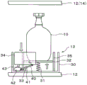
Hereinafter, embodiments of the present invention will be described. Fig. 1 is a front view of a container storage device 1 according to the present embodiment. The container 10 housed in the container housing apparatus 1 stores a processing liquid for semiconductor manufacturing, for example. The processing liquid includes, for example, a resist liquid, a developing liquid, and a chemical liquid for forming an antireflection film.
The container storage apparatus 1 includes a storage rack 11, a shelf 12 provided in multiple stages in the storage rack 11, and a plurality of tables 13 arranged on the upper surface of the shelf 12. In fig. 1, 2 stages of shelves 12 are provided in the vertical direction, and 4 mounting tables 13 are provided on the upper surface of each shelf 12 in the horizontal direction, respectively, but the shape of the storage rack 11, the number and arrangement of the shelves 12 and the mounting tables 13 are not limited to those of the present embodiment, and can be set arbitrarily. Further, a ceiling plate 14 is provided above the shelf plate 12 on the upper side.
The containers 10 for storing the processing liquid are placed on the respective tables 13. A cap 21 integrally connected to the supply pipe 20 inserted into the container 10 is attached to an upper opening of the container 10. The treatment liquid in the container 10 is supplied to the outside of the container 10 via the supply pipe 20 and the cap 21.
For example, as shown in fig. 2, the mounting table 13 includes: a substantially cylindrical mounting plate 30 provided on the upper surface of the shelf 12 and having an open upper surface, for example; a spring 31 extending in the vertical direction on the upper surface of the carriage plate 30; a support plate 32 provided at an end of the spring 31 opposite to the mounting plate 30 and supporting a lower surface of the container 10; a cam mechanism 33 as a displacement transmission member connected to the lower surface of the support plate 32; and a stopper 34 as a moving member that moves up and down by the cam mechanism 33. The side surface of the support plate 32 is slidably supported by a guide 35, for example, in a cylindrical shape. Therefore, when the tank 10 is placed on the support plate 32, the spring 31 expands and contracts according to the amount of the processing liquid in the tank 10, and the support plate 32 moves in the vertical direction, and the vertical movement is transmitted to the cam mechanism 33.
The cam mechanism 33 includes, for example, a connecting rod 40 connected to the lower surface of the support plate 32 and a bearing 41 that slidably supports the connecting rod 40. The connecting rod 40 has a plurality of rotatable joints and is rotatable with the bearing 41 as a viewpoint. An end portion of the connecting rod 40 on the opposite side to the support plate 32 is slidably connected to, for example, an oval cam member 42. Therefore, the cam member 42 moves via the connecting rod 40 in accordance with the vertical movement of the support plate 32.
The stopper 34 is supported on the upper surface of the cam member 42, for example, via a support rod 43 connected to the lower side of the stopper 34. Therefore, the stopper 34 can be moved by operating the cam mechanism 33. Fig. 2 shows a state in which the processing liquid in the container 10 is filled and the stopper 34 is moved to a substantially upper limit position, for example. As shown in fig. 3, for example, the stopper 34 has a semi-cylindrical shape covering a surface (left direction in fig. 3) that the operator contacts when replacing the container 10. The shape of the stopper 34 is not limited to the shape of the present embodiment, and may be, for example, a cylindrical shape covering the outer periphery of the container 10 or a flat plate-like member.
The container storage device 1 according to the present embodiment is configured as described above, and next, the operation of replacing the container 10 in the container storage device 1 will be described.
As shown in fig. 2, in a state where the vessel 10 is filled with the treatment liquid, the spring 31 is pressed down through the support plate 32 in accordance with the weight of the vessel 10. At this time, the spring 31 and the support plate 32 as the displacement mechanism function as a liquid amount detection mechanism that detects the remaining amount of the processing liquid in the tank. Then, in a state where the spring 31 and the support plate 32 are depressed, the stopper 34 is pushed upward by the cam member 42. As described above, when the stopper 34 is pushed upward, the stopper 34 becomes an obstacle, and for example, a gap between the upper shelf 12 or the top plate 14 and the upper end of the stopper 34 becomes small, and the container 10 cannot be moved from the table 13. In other words, the stopper 34 is disposed at a position that prevents the container 10 from being moved from the table 13 to replace the container 10 on the table 13.
When the chemical liquid in the tank 10 decreases, the support plate 32 is gradually pushed up by the spring 31 in accordance with the decrease in the weight of the tank 10. Thereby, for example, as shown in fig. 4, the cam member 42 moves via the connecting rod 40, and the stopper 34 descends. When a predetermined condition is satisfied, specifically, when the processing liquid in the container 10 is substantially empty, the stopper 34 serving as an obstacle is lowered to the lower limit position. In other words, the stopper 34 is retracted from a position that obstructs the movement for replacing the container 10. As a result, the gap between the upper end of the stopper 34 and the shelf 12 or the top plate 14 is secured to such an extent that the container 10 is moved from the mounting table 13, and the container 10 can be replaced. Further, since the stopper 34 is lowered, the position of the stopper 34 in the vertical direction is different from the state of the other container 10 which is not empty, and therefore, the operator can easily confirm the state of the empty container 10 by visual observation by checking the position of the stopper 34.
Then, when the operator confirms the position of the stopper 34 and determines the empty container 10, the operator replaces the container 10. After the replacement of the container 10, the spring 31 and the support plate 32 are lowered by the weight of the new container 10, and along with this, the stopper 34 is again pushed up to the upper limit position by the cam mechanism 33. This causes the container 10 of the table 13 to be again in a state where it cannot be removed by the stopper 34.
In the above embodiment, the stopper 34 is moved up and down relative to the container in accordance with the liquid amount in the container 10, and when the liquid amount is less than a predetermined value, for example, when the container is empty, the stopper is retracted from a position that obstructs the movement of the container 10 for replacement on the mounting table 13, and therefore, it is possible to prevent the container 10 other than the container 10 to be replaced, that is, the container 10 corresponding to the mounting table 13 in which the stopper 34 is not retracted from the position that obstructs the movement of the container 10, from being replaced by mistake at the time of the replacement work of the container 10.
In the normal replacement work of the container 10, for example, the label attached to the container 10 is checked and the empty container 10 is specified, but the identification object such as the label is not always directed to the operator. Therefore, it takes time to determine the empty container 10. In contrast, in the present invention, the position of the stopper 34 is visually confirmed, whereby the container 10 to be replaced can be easily identified. Further, since the stopper 34 operates in accordance with the liquid amount in the container 10, for example, an operator can know the approximate liquid amount in the container 10 by checking the position of the stopper in the height direction on site. This helps to grasp the approximate replacement timing of the container 10. Therefore, according to the present invention, the replacement of the container 10 can be efficiently performed while preventing the replacement error.
Further, since the stopper can be moved up and down by a mechanism such as the cam mechanism 33 and the spring 31 which does not require an electric drive device, for example, special control is not required in a control device of a substrate processing system (not shown) using the container storage apparatus 1. Therefore, the container storage apparatus 1 can be realized at low cost without the problem of an increase in the load of the control apparatus or the occurrence of wiring work.
However, it is not denied that the container storage apparatus 1 uses an electric driving device such as an electric actuator, and an electric or air-operated driving mechanism may be used, for example, which detects the liquid amount in the container 10 by using a measuring mechanism for electrically measuring the displacement amount of the spring 31 and a piezoelectric element for measuring the weight of the container 10, and moves the stopper 34 based on the detection signal.
In the case of electrically measuring the liquid amount in the container 10, for example, a flow meter or a liquid level meter may be provided in the supply pipe 20 in the container 10, and the stopper 34 may be moved when it is determined that the container 10 is replaced after, for example, the detection value of the flow meter is zero and the detection value of the liquid level meter reaches a zero level.
In the above embodiment, the stopper 34 is moved up and down, but the direction of movement of the stopper 34 is not limited to the contents of the present embodiment, and may be set arbitrarily when the container 10 is moved so as to obstruct the movement of the container 10 from the mounting table 13 in a state where the container 10 does not need to be replaced. The mechanism for moving the moving member such as the stopper 34 is not limited to the cam mechanism 33, and various known mechanisms can be used.
As another embodiment, for example, as shown in fig. 5, a pneumatic cylinder 50 or the like may be used as a mechanism for moving the stopper 34 instead of the cam mechanism 33. In the case of using the air cylinder 50, for example, an air bladder 51 which is filled with air and is expandable and contractible in the vertical direction is provided below the support plate 32, and the air bladder 51 and the air cylinder 50 are connected by an air supply pipe 52. Then, the volume of the gas in the air bladder 51 changes with the vertical movement of the support plate 32, and the change in volume is transmitted to the pneumatic cylinder via the gas supply pipe 52, whereby the stopper 34 is moved up and down by the pneumatic cylinder 50 via the support rod 43.
In addition, in the case of using the air cylinder 50, the air bladder 51 is not necessarily provided. For example, the support plate 32 and the guide 35 may be configured such that a space a surrounded by the support plate 32 and the guide 35 can be maintained airtight, and the gas supply pipe 52 may be provided so as to communicate with the space a surrounded by the support plate 32 and the guide 35. In this case, the space a also functions as an air bag, and since the change in volume of the space a is transmitted from the air supply pipe 52 to the air pressure cylinder 50, the stopper 34 can be moved up and down by the air pressure cylinder. Since other configurations are the same as those in fig. 2, the description thereof is omitted.
As another embodiment, for example, as shown in fig. 6, a rack and a gear 60 may be used as a displacement transmission member for transmitting the movement of the support plate 32 to the stopper 34. In this case, for example, one rack 61 is connected to the support plate 32, and another rack 63 is provided via a gear 62 provided on the outer side of the guide 35. Further, the position of the gear 62 in the height direction is fixedly set. In fig. 6, for example, the other rack 63 is directly fixed to the stopper 34.
Then, for example, as shown in fig. 7, after the container 10 is replaced, the rack 61 moves downward together with the support plate 32, and thereby another rack 63 provided through the gear 62 is raised, and the stopper 34 is raised to a position where replacement of the container 10 is hindered. Since other configurations are the same as those in fig. 2, the description thereof is omitted.
The member for blocking the movement of the container 10 is not limited to the stopper 34, and various members can be used. For example, as shown in fig. 8, an air bladder 70 may be provided in the space between the guide 35 and the carriage plate 30 as a moving member in place of the stopper 34. In this case, a space a surrounded by the support plate 32 and the guide 35 is configured to be airtight, and the air supply pipe 52 is provided to communicate with the space a and the air bladder 70. Other configurations are the same as those in fig. 2.
As shown in fig. 8, in a state where the container 10 is filled with the processing liquid, the space a is compressed, the gas in the space a moves to the air bladder 70, and the air bladder 70 expands upward. Thus, the air bladder 70 functions to hinder the movement of the container 10 for replacement. When the processing liquid in the tank 10 decreases, the support plate 32 is pushed upward by the spring 31, and the volume of the space a increases. As a result, gas flows from the air bladder 70 into the space a via the gas supply pipe 52, and the air bladder 70 is contracted to be in a state in which the container 10 can be replaced, as shown in fig. 9. In addition, when an air bladder is used instead of the stopper 34, the use of an electric driving device or an electric measuring device is not necessarily denied. For example, as in the case of electrically moving the stopper 34, the remaining amount of the processing liquid in the container 10 may be electrically measured, and the air bladder 70 may be expanded by supplying gas into the air bladder 70 by, for example, an air compressor or the like, and the air bladder 70 may be contracted by exhausting gas by using an electromagnetic valve or the like, based on the remaining amount.
In the above embodiment, the stopper 34 is used as a moving member that moves so as to prevent replacement of the container 10, but the member used as a moving member is not limited to the stopper. For example, as shown in fig. 10 and 11, a holding member 80 formed in a substantially U shape for holding the container 10 so as to sandwich the cap 21 at a position lower than the cap 21 of the container 10 may be provided, and the holding member 80 may be operated in conjunction with the vertical movement of the support plate 32.
In this case, the holding member 80 is provided on the opposite side of the side (left direction in fig. 10 and 11) that the operator touches when replacing the container 10 of the table 13. Further, a movable mechanism 81 for moving the holding member 80 in the θ direction in fig. 11 in accordance with the vertical movement of the connecting rod 40 connected to the lower surface of the support plate 32 is provided, and the end of the holding member 80 on the side opposite to the holding container 10 is supported by the movable mechanism 81. Thus, for example, as shown in fig. 11, when the container 10 immediately after replacement is placed on the placement table 13, the holding member 80 functions to restrain the container 10 from moving from above and to prevent the movement of the container 10.
When the processing liquid in the container 10 decreases, the holding member 80 is operated to rise from the horizontal direction to the vertical direction gradually with the movable mechanism 81 as a fulcrum, and when the container 10 is emptied, it is moved to a position retracted from above the container 10 as shown in fig. 12, for example. This allows the container 10 to be replaced without being hindered from moving by the holding member 80.
In the above embodiment, the stopper 34 and the holding member 80 are moved via the cam mechanism 33 and the movable mechanism 81 according to the amount of the processing liquid in the container 10, but for example, the displacement transmission member such as the lower cam mechanism 33 and the movable mechanism 81 may be easily removed and removed at an irregular time, so that the container 10 that is not empty can be removed.
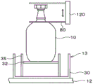
Similarly to the case where the stopper 34 is moved by the electric drive device, for example, the movable mechanism 81 may be replaced by an electric drive mechanism 90 shown in fig. 13 that electrically measures the remaining amount of the processing liquid in the container 10 and moves the holding member 80 according to the remaining amount. As the driving mechanism 90, for example, an electric actuator, an air cylinder, or the like can be used. In this case, the holding member 80 is rotated by the driving mechanism 90 so as to stand in the vertical direction when the container 10 is replaced, and in other cases, that is, in cases where the container 10 is not replaced, the holding member 80 is rotated so as to be oriented in the horizontal direction, so that it is possible to prevent the container 10 from being replaced by an error. In the case of using the electrically driven driving mechanism 90, as shown in fig. 13, a mechanism such as the cam mechanism 33 and the spring 31 is not required, and the support plate 32 does not need to be lifted or lowered. In this case, the container 10 may be directly placed on the placement plate 30.
In addition, when the amount of the liquid in the container 10 is electrically measured, for example, as shown in fig. 13, a liquid level gauge 91 is provided at a position near the bottom surface of the container 10 at the substantially distal end of the supply pipe 20 to detect the presence or absence of the treatment liquid in the vicinity of the bottom surface of the container 10, or, for example, as shown in fig. 13, a flow meter 101 as a flow rate detection means is provided in an external supply pipe 100 through which the treatment liquid is supplied from the container 10 to a target, and the presence or absence of the treatment liquid flowing in the external supply pipe 100 is detected, whereby the presence or absence of the treatment liquid in the container 10 can be detected. When the liquid level gauge 91 is used, it is possible to determine the replacement timing of the container 10 after the detection value of the liquid level gauge 91 becomes zero, for example. In addition, even when the flow meter 101 is used, it can be determined that the container 10 is replaced after the detection value of the flow meter 101 becomes zero. The detection value of the liquid level gauge 91 and the detection value of the flow meter 101 are input to the control device 102, and the control device 102 controls the operation of the driving mechanism 90 based on the detection values.
Although fig. 13 illustrates a case where the holding member 80 is rotated between the vertical direction and the horizontal direction by the driving mechanism 90, how to move the holding member 80 is not limited to the contents of the present embodiment, and for example, as illustrated in fig. 14, a driving mechanism 110 may be provided that reciprocates the holding member 80 held in the horizontal state in the horizontal direction, and the holding member 80 may be moved, for example, to the left in fig. 14 to hinder the movement for replacement of the container 10, and moved to the right in fig. 14 to enable the container 10 to be replaced. Further, as shown in fig. 15, for example, a driving mechanism 120 is provided for reciprocating the holding member 80 held in a horizontal state in the vertical direction, and by moving the holding member 80 downward in fig. 15, for example, the movement for replacement of the container 10 is inhibited, and by moving it upward in fig. 15, the container 10 can be replaced. Although the drawings of the control device 102, the liquid level meter 91, and the flow meter 101 are omitted in fig. 14 and 15, the above-described devices may be provided as appropriate as needed in other embodiments described below.
The shape of the holding member 80 is not limited to the content of the present embodiment, and may be arbitrarily set as long as it functions to prevent the movement of the container 10 when the container 10 is replaced. For example, as shown in fig. 16, semicircular holding members 130a and 130b may be disposed at a position lower than the cap 21 of the container 10 in plan view so as to sandwich the vicinity of the cap 21, and the holding members 130a and 130b may be moved in the horizontal direction (vertical direction in fig. 16) by a driving mechanism 131.
The holding member 80 does not need to hold the container 10 itself, and for example, as shown in fig. 17, a substantially flat plate-shaped holding member 140 may be disposed at a position near the upper side of the cap 21 covering the position of the cap 21 of the container 10 in a plan view, to regulate the movement of the container 10 in the vertical direction, and to hinder the movement for replacing the container 10. In this case, as the operation of the holding member 140, for example, the driving mechanism 110 shown in fig. 14 may be used to move in the left-right direction of fig. 17, for example, the driving mechanism 120 shown in fig. 15 may be used to move in the vertical direction, or the driving mechanism 131 shown in fig. 16 may be used to move in the vertical direction of fig. 17.
In fig. 17, a substantially flat plate-shaped holding member 140 is provided near the upper side of the cap 21, but instead of the holding member 140, for example, the cap 21 may be surrounded by a lid 141 having an open bottom surface as shown in fig. 18 to restrict the movement of the container 10 in the vertical direction, and the cap 21 may be retracted upward by the driving mechanism 120 as necessary, and the shapes of the holding member and the lid may be arbitrarily set without being limited to the contents of the present embodiment. In addition, from the viewpoint of relatively moving the vessel 10, the holding members 80, 140, and the lid 141, it is not always necessary to move the holding members 80, 140, and the lid 141, and for example, the vessel 10 itself may be moved relative to the holding members 80, 140, and the lid 141 by connecting the driving mechanism 120 shown in fig. 15 to the support plate 32.
When the container 10 itself is moved, for example, as shown in fig. 19, the spring 31 is disposed at a position offset from the center of the container 10, and the end of the support plate 32 on the side opposite to the side supported by the spring 31 is fixed to the guide 35 by a hinge 142 so as to be freely rotatable, and a holding member 140 is provided above the cap 21 of the container 10. The hinge 142 side in fig. 19 is a contact surface. In this case, when the processing liquid in the tank 10 decreases, the end portion of the support plate 32 opposite to the hinge 142 is gradually pushed up by the spring 31, and the tank 10 is inclined in the direction of the contact surface, as shown in fig. 20, for example. Thus, for example, the cap 21 is moved to a position where it does not interfere with the holding member 140 in a plan view, and the container 10 can be drawn out in an oblique direction from the mounting table 13. It is understood that in this case, the mechanism for moving the vessel 10 to incline, such as the spring 31, the support plate 32, and the hinge 142, is also within the scope of the moving member of the present invention that moves so as to hinder the replacement of the vessel 10.
As another embodiment of the case of using the stoppers, instead of the semicircular cylindrical stoppers 34 described above, for example, flat stoppers 150a and 150b having a predetermined height shown in fig. 21 and 22 may be provided on a surface (left direction in fig. 21 and left direction in fig. 22) which the operator contacts, and a rotation shaft 151 such as a hinge may be provided at an end of the stoppers 150a and 150b to open and close the door. In this case, for example, when the container 10 does not need to be replaced, the rotary shaft 151 is fixed by an electromagnetic brake (not shown) so that the stoppers 150a and 150b cannot be opened and closed, and when the liquid level gauge 91 and the flow meter 101 detect that replacement is necessary, the electromagnetic brake is released, and the operator opens the stoppers 150a and 150b to contact the container 10.
In the above embodiment, the stopper 34, the stoppers 150a, 150b, and other members that block the movement of the container 10 are disposed inside the placement plate 30, for example, but the disposition thereof is not limited to the content of the present embodiment. For example, as shown in fig. 23, a rod-like member 152 having a substantially U-shape that blocks the movement of the container 10 and a drive mechanism 153 that rotates the rod-like member 152 toward the surface on the operator contact side as shown in fig. 24 may be provided in front of the container 10 as viewed from the surface on the operator contact side. Fig. 24 is a diagram showing the state of the container 10 as viewed from the right side surface of fig. 23, and the left direction of fig. 24 is a contact surface of the operator. In addition, when the rod member 152 is rotated, for example, as shown in fig. 25, another rack 63 and the stopper 34 may be removed from the mounting table 13 shown in fig. 6, the gear 62 whose position in the height direction is fixed may be connected to the rod member 152, and the rod member 152 may be rotated by the rotation of the gear 62.
In addition, from the viewpoint of preventing erroneous replacement of the container 10 which does not require replacement, the movement of the container 10 itself does not necessarily need to be hindered. The cap 21 is usually provided with a rotation prevention bracket 160 as shown in fig. 26, for example. Therefore, for example, as shown in fig. 26, a fixing member 161 for fixing the holder 160 and a driving mechanism 162 for moving the fixing member 161 are provided, and when the container 10 does not need to be replaced, the fixing member 161 is moved to the position of the fixing holder 160, and when the container needs to be replaced, the fixing member 161 is moved so as to release the fixing of the holder 160. As described above, the fixing member 161 and the driving mechanism 162 that prevent the cap 21 from being removed from the container 10 are also within the scope of the moving member of the present invention that prevents the container 10 from being replaced.
In the above embodiment, the air bladder 70 is expanded and contracted as an alternative to the stopper 34, but for example, as shown in fig. 27, when the annular air bladder 170 is disposed along the inner peripheral surface of the mounting plate 30 and the liquid level gauge 91 and the flow meter 101 detect that the container 10 needs to be replaced, gas may be supplied to the air bladder 170 from a gas supply source, not shown, via the gas supply pipe 52. By supplying the gas, the container 10 is held by the air bladder 170, and the movement of the container 10 for replacement can be inhibited.
In the case of the electric mechanism, it is conceivable to provide, for example, a display lamp 180 for identifying the container 10 to be replaced, in addition to electrically moving the holding member 80 or electrically detecting the remaining amount of the processing liquid in the container 10. In this case, as shown in fig. 28, for example, indicator lamps 180 are provided near the tables 13, and the indicator lamps 180 corresponding to the containers 10 that can be moved to the container replacement position are turned on. In addition, since a plurality of substrate processing systems (not shown) using the container storage apparatus 1 are usually installed in a clean room, a plurality of container storage apparatuses 1 are also installed. Therefore, it may be difficult to determine at a glance which container 10 of the container storage apparatus 1 is the replacement target. In this case, for example, as shown in fig. 28, a display lamp 181 is provided at an arbitrary portion such as the top plate 14 of the container storage apparatus 1 that is easily visually checked, and it is possible to determine at a glance which container storage apparatus 1 has the container 10 to be replaced. The on/off of the indicator lamps 180 and 181 is controlled by the controller 102, for example.
In the above embodiment, the case where the liquid amount of the treatment liquid in the tank 10 is less than the predetermined amount and the tank 10 needs to be replaced has been described as an example as the predetermined condition for bringing the tank 10 into the replaceable state, but the predetermined condition for bringing the tank 10 into the replaceable state is not limited to the content of the present embodiment. For example, when the type of the processing liquid used in the substrate processing system (not shown) is changed, the tank 10 may need to be replaced regardless of the remaining amount of the processing liquid in the tank 10. In this case, for example, as shown in fig. 13, a switch 102a is provided in the control device 102, and the drive mechanism 90 can be directly operated from the switch 102a regardless of the detection value of the liquid level gauge 91 or the detection value of the flow meter 101. Similarly, the on/off of the indicator lamps 180 and 181 may be controlled by the switch 102 a.
The preferred embodiments of the present invention have been described above with reference to the drawings, but the present invention is not limited to these examples. It is understood that various modifications and alterations can be made by those skilled in the art within the scope of the idea described in the claims, and they naturally fall within the technical scope of the present invention. The present invention is not limited to this example, and various methods can be adopted. In the above embodiment, the case where the container housing apparatus 1 houses the container for storing the processing liquid for manufacturing the semiconductor wafer has been described as an example, but the processing liquid is not limited to the processing liquid for manufacturing the semiconductor wafer, and it is needless to say that the present invention is also applicable to a case where, for example, the container houses an adhesive agent used in an adhesion process for bonding the semiconductor wafers to each other.
Industrial applicability of the invention
The present invention is useful for housing a container for storing a treatment liquid.
Description of the reference numerals
1 Container storage device
10 container
11 storage rack
12 racks
13 placing table
14 Top plate
20 supply pipe
21 Cap
30 carrying plate
31 spring
32 support plate
33 cam mechanism
34 baffle
35 guide piece
40 connecting rod
41 bearing
42 cam part
50 air compression cylinder
60 rack and pinion
70 air bag
80 holding member
Claims (6)
1. A container storage apparatus that stores a plurality of containers storing a processing liquid for semiconductor manufacturing, the container storage apparatus comprising:
a plurality of tables on which the container is placed;
a liquid amount detection mechanism that detects a liquid amount of the processing liquid in the container; and
a moving means which is provided separately from the mounting table, is disposed at a position where movement of the tank from the mounting table for replacement of the tank on the mounting table is inhibited, and is retracted from the position where movement for replacement of the tank is inhibited by a change in relative position with respect to the tank on the mounting table when the amount of the processing liquid in the tank detected by the liquid amount detecting means is less than a predetermined value,
the relative position of the moving member with respect to the container on the mounting table changes in accordance with the liquid amount detected by the liquid amount detection mechanism.
2. The container receptacle of claim 1, wherein:
the liquid amount detection means is a displacement means for displacing a position in a height direction in accordance with a weight of the container placed on the placement table,
a displacement transmission member is connected to the displacement mechanism, and transmits a change in position of the displacement mechanism to the moving member to move the moving member.
3. The container receptacle of claim 1, wherein:
the liquid amount detection mechanism includes an air bag that changes an internal gas volume according to a weight of a container placed on the placement table,
the air bladder is connected to a cylinder mechanism that moves the moving member according to the volume of gas inside the air bladder.
4. A container receptacle according to any one of claims 1 to 3, wherein:
the moving member is a stopper that moves in the vertical direction on the side of the container.
5. A container receptacle according to any one of claims 1 to 3, wherein:
the moving member is located above the container so as to block the vertical movement of the container when the liquid amount of the treatment liquid in the container is equal to or greater than a predetermined value, and moves to a position retracted from above the container when the liquid amount of the treatment liquid in the container is less than the predetermined value.
6. A container storage apparatus that stores a plurality of containers storing a processing liquid for semiconductor manufacturing, the container storage apparatus comprising:
a plurality of tables on which the container is placed;
a moving member provided separately from the mounting table and disposed at a position where movement of the container from the mounting table for replacement of the container on the mounting table is inhibited;
a drive mechanism that moves the moving member;
a flow rate detection means for detecting a flow rate of the treatment liquid supplied from the container to the outside; and
and a control unit that controls the drive mechanism so that the moving member is retracted from a position where movement for replacing the container is inhibited when the flow rate detected by the flow rate detection mechanism is lower than a predetermined value.
Applications Claiming Priority (5)
| Application Number | Priority Date | Filing Date | Title |
|---|---|---|---|
| JP2014-193581 | 2014-09-24 | ||
| JP2014193581 | 2014-09-24 | ||
| JP2015158322A JP6342368B2 (en) | 2014-09-24 | 2015-08-10 | Container container |
| JP2015-158322 | 2015-08-10 | ||
| PCT/JP2015/076422 WO2016047542A1 (en) | 2014-09-24 | 2015-09-17 | Container accommodation device |
Publications (2)
| Publication Number | Publication Date |
|---|---|
| CN106716598A CN106716598A (en) | 2017-05-24 |
| CN106716598B true CN106716598B (en) | 2020-08-14 |
Family
ID=55805865
Family Applications (1)
| Application Number | Title | Priority Date | Filing Date |
|---|---|---|---|
| CN201580051716.7A Active CN106716598B (en) | 2014-09-24 | 2015-09-17 | Container storage device |
Country Status (3)
| Country | Link |
|---|---|
| JP (1) | JP6342368B2 (en) |
| CN (1) | CN106716598B (en) |
| TW (1) | TWI639540B (en) |
Families Citing this family (2)
| Publication number | Priority date | Publication date | Assignee | Title |
|---|---|---|---|---|
| TWI763944B (en) * | 2017-11-01 | 2022-05-11 | 日商東京威力科創股份有限公司 | Process liquid supply system, process liquid supply device, and carrier storage device |
| CN113329910B (en) | 2019-01-22 | 2024-02-06 | 上海延锋金桥汽车饰件系统有限公司 | Vehicle interior component |
Citations (3)
| Publication number | Priority date | Publication date | Assignee | Title |
|---|---|---|---|---|
| KR20040082483A (en) * | 2003-03-19 | 2004-09-30 | 삼성전자주식회사 | Devices for suppling photoresist |
| KR20050088734A (en) * | 2004-03-03 | 2005-09-07 | 삼성전자주식회사 | Apparatus for supplying photoresist |
| CN101364046A (en) * | 2007-08-06 | 2009-02-11 | 力晶半导体股份有限公司 | Detecting and early-warning system for liquid and liquid level and method |
Family Cites Families (5)
| Publication number | Priority date | Publication date | Assignee | Title |
|---|---|---|---|---|
| JP3060136B2 (en) * | 1991-12-04 | 2000-07-10 | 東京エレクトロン株式会社 | Semiconductor manufacturing equipment |
| JP3680907B2 (en) * | 1998-06-02 | 2005-08-10 | 大日本スクリーン製造株式会社 | Substrate processing equipment |
| JP4708044B2 (en) * | 2005-02-10 | 2011-06-22 | 大日本スクリーン製造株式会社 | Substrate processing equipment |
| JP5612265B2 (en) * | 2009-01-23 | 2014-10-22 | 株式会社Screenセミコンダクターソリューションズ | Substrate processing apparatus and substrate processing method |
| JP5841007B2 (en) * | 2012-05-28 | 2016-01-06 | 株式会社Screenセミコンダクターソリューションズ | Chemical supply method and substrate processing apparatus |
-
2015
- 2015-08-10 JP JP2015158322A patent/JP6342368B2/en active Active
- 2015-09-17 CN CN201580051716.7A patent/CN106716598B/en active Active
- 2015-09-21 TW TW104131060A patent/TWI639540B/en active
Patent Citations (3)
| Publication number | Priority date | Publication date | Assignee | Title |
|---|---|---|---|---|
| KR20040082483A (en) * | 2003-03-19 | 2004-09-30 | 삼성전자주식회사 | Devices for suppling photoresist |
| KR20050088734A (en) * | 2004-03-03 | 2005-09-07 | 삼성전자주식회사 | Apparatus for supplying photoresist |
| CN101364046A (en) * | 2007-08-06 | 2009-02-11 | 力晶半导体股份有限公司 | Detecting and early-warning system for liquid and liquid level and method |
Also Published As
| Publication number | Publication date |
|---|---|
| CN106716598A (en) | 2017-05-24 |
| JP6342368B2 (en) | 2018-06-13 |
| TW201632435A (en) | 2016-09-16 |
| JP2016066784A (en) | 2016-04-28 |
| TWI639540B (en) | 2018-11-01 |
Similar Documents
| Publication | Publication Date | Title |
|---|---|---|
| CN103370628B (en) | The service of connection devices of laboratory automatic system between the pneumatic postal delivery system and feed system of bioproduct containers | |
| KR102440278B1 (en) | Filling station for gas bottles and filling method | |
| CN107924856B (en) | Blowing-out device, blowing-out stocker, and blowing-out method | |
| US10775400B2 (en) | Feeding apparatus | |
| CN105793714A (en) | Automatic analytical apparatus | |
| JP2009036511A (en) | Specimen pretreating system | |
| CN106716598B (en) | Container storage device | |
| EP3078423B1 (en) | Reagent bottle docking | |
| EP2492692A1 (en) | Heat insulator | |
| CA2565149A1 (en) | Detection device, components of a detection device, and methods associated therewith | |
| WO2016012439A1 (en) | Cup catcher device | |
| JP2016192495A (en) | Gas purge device, load port device, installation base of container to be purged, and gas purge method | |
| WO2013178518A1 (en) | Carrier element and packaging device for packaging at least one product into at least one packaging | |
| EP3112071B1 (en) | Solder supply system | |
| CN109696556B (en) | Pipetting device and pipetting device positioning system | |
| EP2919016B1 (en) | Dispenser | |
| JP5178891B2 (en) | Automatic analyzer | |
| KR102380665B1 (en) | Container accommodation device | |
| EP2244832B1 (en) | Fail-safe method and apparatus for aspirating and/or dispensing liquids in automated laboratory instruments | |
| KR102326014B1 (en) | Apparatus for storing gas cylinders | |
| KR102326015B1 (en) | Apparatus for storing gas cylinders | |
| US20180231456A1 (en) | Inspection apparatus and inspection method | |
| JP7006554B2 (en) | Sample transfer device | |
| WO2016009765A1 (en) | Automatic analysis device | |
| JPWO2019003789A1 (en) | Unit for loading or storing sample container, and sample inspection automation system including the unit |
Legal Events
| Date | Code | Title | Description |
|---|---|---|---|
| PB01 | Publication | ||
| PB01 | Publication | ||
| SE01 | Entry into force of request for substantive examination | ||
| GR01 | Patent grant | ||
| GR01 | Patent grant |