CN106574665B - Device for inspecting joint type outer joint member of constant velocity universal joint - Google Patents
Device for inspecting joint type outer joint member of constant velocity universal joint Download PDFInfo
- Publication number
- CN106574665B CN106574665B CN201580040642.7A CN201580040642A CN106574665B CN 106574665 B CN106574665 B CN 106574665B CN 201580040642 A CN201580040642 A CN 201580040642A CN 106574665 B CN106574665 B CN 106574665B
- Authority
- CN
- China
- Prior art keywords
- cup
- inspection
- outer joint
- welding
- shaft
- Prior art date
- Legal status (The legal status is an assumption and is not a legal conclusion. Google has not performed a legal analysis and makes no representation as to the accuracy of the status listed.)
- Active
Links
Images


Classifications
-
- G—PHYSICS
- G01—MEASURING; TESTING
- G01N—INVESTIGATING OR ANALYSING MATERIALS BY DETERMINING THEIR CHEMICAL OR PHYSICAL PROPERTIES
- G01N29/00—Investigating or analysing materials by the use of ultrasonic, sonic or infrasonic waves; Visualisation of the interior of objects by transmitting ultrasonic or sonic waves through the object
- G01N29/04—Analysing solids
- G01N29/043—Analysing solids in the interior, e.g. by shear waves
-
- B—PERFORMING OPERATIONS; TRANSPORTING
- B23—MACHINE TOOLS; METAL-WORKING NOT OTHERWISE PROVIDED FOR
- B23K—SOLDERING OR UNSOLDERING; WELDING; CLADDING OR PLATING BY SOLDERING OR WELDING; CUTTING BY APPLYING HEAT LOCALLY, e.g. FLAME CUTTING; WORKING BY LASER BEAM
- B23K31/00—Processes relevant to this subclass, specially adapted for particular articles or purposes, but not covered by only one of the preceding main groups
- B23K31/12—Processes relevant to this subclass, specially adapted for particular articles or purposes, but not covered by only one of the preceding main groups relating to investigating the properties, e.g. the weldability, of materials
- B23K31/125—Weld quality monitoring
-
- F—MECHANICAL ENGINEERING; LIGHTING; HEATING; WEAPONS; BLASTING
- F16—ENGINEERING ELEMENTS AND UNITS; GENERAL MEASURES FOR PRODUCING AND MAINTAINING EFFECTIVE FUNCTIONING OF MACHINES OR INSTALLATIONS; THERMAL INSULATION IN GENERAL
- F16D—COUPLINGS FOR TRANSMITTING ROTATION; CLUTCHES; BRAKES
- F16D1/00—Couplings for rigidly connecting two coaxial shafts or other movable machine elements
- F16D1/02—Couplings for rigidly connecting two coaxial shafts or other movable machine elements for connecting two abutting shafts or the like
- F16D1/027—Couplings for rigidly connecting two coaxial shafts or other movable machine elements for connecting two abutting shafts or the like non-disconnectable, e.g. involving gluing, welding or the like
-
- F—MECHANICAL ENGINEERING; LIGHTING; HEATING; WEAPONS; BLASTING
- F16—ENGINEERING ELEMENTS AND UNITS; GENERAL MEASURES FOR PRODUCING AND MAINTAINING EFFECTIVE FUNCTIONING OF MACHINES OR INSTALLATIONS; THERMAL INSULATION IN GENERAL
- F16D—COUPLINGS FOR TRANSMITTING ROTATION; CLUTCHES; BRAKES
- F16D3/00—Yielding couplings, i.e. with means permitting movement between the connected parts during the drive
- F16D3/16—Universal joints in which flexibility is produced by means of pivots or sliding or rolling connecting parts
- F16D3/20—Universal joints in which flexibility is produced by means of pivots or sliding or rolling connecting parts one coupling part entering a sleeve of the other coupling part and connected thereto by sliding or rolling members
-
- G—PHYSICS
- G01—MEASURING; TESTING
- G01N—INVESTIGATING OR ANALYSING MATERIALS BY DETERMINING THEIR CHEMICAL OR PHYSICAL PROPERTIES
- G01N21/00—Investigating or analysing materials by the use of optical means, i.e. using sub-millimetre waves, infrared, visible or ultraviolet light
- G01N21/84—Systems specially adapted for particular applications
- G01N21/88—Investigating the presence of flaws or contamination
- G01N21/95—Investigating the presence of flaws or contamination characterised by the material or shape of the object to be examined
-
- G—PHYSICS
- G01—MEASURING; TESTING
- G01N—INVESTIGATING OR ANALYSING MATERIALS BY DETERMINING THEIR CHEMICAL OR PHYSICAL PROPERTIES
- G01N29/00—Investigating or analysing materials by the use of ultrasonic, sonic or infrasonic waves; Visualisation of the interior of objects by transmitting ultrasonic or sonic waves through the object
- G01N29/04—Analysing solids
- G01N29/041—Analysing solids on the surface of the material, e.g. using Lamb, Rayleigh or shear waves
-
- G—PHYSICS
- G01—MEASURING; TESTING
- G01N—INVESTIGATING OR ANALYSING MATERIALS BY DETERMINING THEIR CHEMICAL OR PHYSICAL PROPERTIES
- G01N29/00—Investigating or analysing materials by the use of ultrasonic, sonic or infrasonic waves; Visualisation of the interior of objects by transmitting ultrasonic or sonic waves through the object
- G01N29/22—Details, e.g. general constructional or apparatus details
- G01N29/26—Arrangements for orientation or scanning by relative movement of the head and the sensor
- G01N29/275—Arrangements for orientation or scanning by relative movement of the head and the sensor by moving both the sensor and the material
-
- G—PHYSICS
- G01—MEASURING; TESTING
- G01N—INVESTIGATING OR ANALYSING MATERIALS BY DETERMINING THEIR CHEMICAL OR PHYSICAL PROPERTIES
- G01N29/00—Investigating or analysing materials by the use of ultrasonic, sonic or infrasonic waves; Visualisation of the interior of objects by transmitting ultrasonic or sonic waves through the object
- G01N29/22—Details, e.g. general constructional or apparatus details
- G01N29/28—Details, e.g. general constructional or apparatus details providing acoustic coupling, e.g. water
-
- G—PHYSICS
- G01—MEASURING; TESTING
- G01N—INVESTIGATING OR ANALYSING MATERIALS BY DETERMINING THEIR CHEMICAL OR PHYSICAL PROPERTIES
- G01N29/00—Investigating or analysing materials by the use of ultrasonic, sonic or infrasonic waves; Visualisation of the interior of objects by transmitting ultrasonic or sonic waves through the object
- G01N29/44—Processing the detected response signal, e.g. electronic circuits specially adapted therefor
- G01N29/48—Processing the detected response signal, e.g. electronic circuits specially adapted therefor by amplitude comparison
-
- G—PHYSICS
- G05—CONTROLLING; REGULATING
- G05B—CONTROL OR REGULATING SYSTEMS IN GENERAL; FUNCTIONAL ELEMENTS OF SUCH SYSTEMS; MONITORING OR TESTING ARRANGEMENTS FOR SUCH SYSTEMS OR ELEMENTS
- G05B19/00—Programme-control systems
- G05B19/02—Programme-control systems electric
- G05B19/418—Total factory control, i.e. centrally controlling a plurality of machines, e.g. direct or distributed numerical control [DNC], flexible manufacturing systems [FMS], integrated manufacturing systems [IMS], computer integrated manufacturing [CIM]
- G05B19/4183—Total factory control, i.e. centrally controlling a plurality of machines, e.g. direct or distributed numerical control [DNC], flexible manufacturing systems [FMS], integrated manufacturing systems [IMS], computer integrated manufacturing [CIM] characterised by data acquisition, e.g. workpiece identification
-
- B—PERFORMING OPERATIONS; TRANSPORTING
- B21—MECHANICAL METAL-WORKING WITHOUT ESSENTIALLY REMOVING MATERIAL; PUNCHING METAL
- B21K—MAKING FORGED OR PRESSED METAL PRODUCTS, e.g. HORSE-SHOES, RIVETS, BOLTS OR WHEELS
- B21K1/00—Making machine elements
- B21K1/76—Making machine elements elements not mentioned in one of the preceding groups
- B21K1/762—Coupling members for conveying mechanical motion, e.g. universal joints
- B21K1/765—Outer elements of coupling members
-
- B—PERFORMING OPERATIONS; TRANSPORTING
- B23—MACHINE TOOLS; METAL-WORKING NOT OTHERWISE PROVIDED FOR
- B23K—SOLDERING OR UNSOLDERING; WELDING; CLADDING OR PLATING BY SOLDERING OR WELDING; CUTTING BY APPLYING HEAT LOCALLY, e.g. FLAME CUTTING; WORKING BY LASER BEAM
- B23K15/00—Electron-beam welding or cutting
- B23K15/0046—Welding
- B23K15/0053—Seam welding
-
- B—PERFORMING OPERATIONS; TRANSPORTING
- B23—MACHINE TOOLS; METAL-WORKING NOT OTHERWISE PROVIDED FOR
- B23K—SOLDERING OR UNSOLDERING; WELDING; CLADDING OR PLATING BY SOLDERING OR WELDING; CUTTING BY APPLYING HEAT LOCALLY, e.g. FLAME CUTTING; WORKING BY LASER BEAM
- B23K26/00—Working by laser beam, e.g. welding, cutting or boring
- B23K26/20—Bonding
- B23K26/21—Bonding by welding
-
- F—MECHANICAL ENGINEERING; LIGHTING; HEATING; WEAPONS; BLASTING
- F16—ENGINEERING ELEMENTS AND UNITS; GENERAL MEASURES FOR PRODUCING AND MAINTAINING EFFECTIVE FUNCTIONING OF MACHINES OR INSTALLATIONS; THERMAL INSULATION IN GENERAL
- F16D—COUPLINGS FOR TRANSMITTING ROTATION; CLUTCHES; BRAKES
- F16D3/00—Yielding couplings, i.e. with means permitting movement between the connected parts during the drive
- F16D3/16—Universal joints in which flexibility is produced by means of pivots or sliding or rolling connecting parts
- F16D3/20—Universal joints in which flexibility is produced by means of pivots or sliding or rolling connecting parts one coupling part entering a sleeve of the other coupling part and connected thereto by sliding or rolling members
- F16D3/22—Universal joints in which flexibility is produced by means of pivots or sliding or rolling connecting parts one coupling part entering a sleeve of the other coupling part and connected thereto by sliding or rolling members the rolling members being balls, rollers, or the like, guided in grooves or sockets in both coupling parts
- F16D3/223—Universal joints in which flexibility is produced by means of pivots or sliding or rolling connecting parts one coupling part entering a sleeve of the other coupling part and connected thereto by sliding or rolling members the rolling members being balls, rollers, or the like, guided in grooves or sockets in both coupling parts the rolling members being guided in grooves in both coupling parts
- F16D2003/22326—Attachments to the outer joint member, i.e. attachments to the exterior of the outer joint member or to the shaft of the outer joint member
-
- F—MECHANICAL ENGINEERING; LIGHTING; HEATING; WEAPONS; BLASTING
- F16—ENGINEERING ELEMENTS AND UNITS; GENERAL MEASURES FOR PRODUCING AND MAINTAINING EFFECTIVE FUNCTIONING OF MACHINES OR INSTALLATIONS; THERMAL INSULATION IN GENERAL
- F16D—COUPLINGS FOR TRANSMITTING ROTATION; CLUTCHES; BRAKES
- F16D2250/00—Manufacturing; Assembly
- F16D2250/0061—Joining
- F16D2250/0076—Welding, brazing
-
- F—MECHANICAL ENGINEERING; LIGHTING; HEATING; WEAPONS; BLASTING
- F16—ENGINEERING ELEMENTS AND UNITS; GENERAL MEASURES FOR PRODUCING AND MAINTAINING EFFECTIVE FUNCTIONING OF MACHINES OR INSTALLATIONS; THERMAL INSULATION IN GENERAL
- F16D—COUPLINGS FOR TRANSMITTING ROTATION; CLUTCHES; BRAKES
- F16D3/00—Yielding couplings, i.e. with means permitting movement between the connected parts during the drive
- F16D3/16—Universal joints in which flexibility is produced by means of pivots or sliding or rolling connecting parts
- F16D3/20—Universal joints in which flexibility is produced by means of pivots or sliding or rolling connecting parts one coupling part entering a sleeve of the other coupling part and connected thereto by sliding or rolling members
- F16D3/202—Universal joints in which flexibility is produced by means of pivots or sliding or rolling connecting parts one coupling part entering a sleeve of the other coupling part and connected thereto by sliding or rolling members one coupling part having radially projecting pins, e.g. tripod joints
- F16D3/205—Universal joints in which flexibility is produced by means of pivots or sliding or rolling connecting parts one coupling part entering a sleeve of the other coupling part and connected thereto by sliding or rolling members one coupling part having radially projecting pins, e.g. tripod joints the pins extending radially outwardly from the coupling part
- F16D3/2055—Universal joints in which flexibility is produced by means of pivots or sliding or rolling connecting parts one coupling part entering a sleeve of the other coupling part and connected thereto by sliding or rolling members one coupling part having radially projecting pins, e.g. tripod joints the pins extending radially outwardly from the coupling part having three pins, i.e. true tripod joints
-
- F—MECHANICAL ENGINEERING; LIGHTING; HEATING; WEAPONS; BLASTING
- F16—ENGINEERING ELEMENTS AND UNITS; GENERAL MEASURES FOR PRODUCING AND MAINTAINING EFFECTIVE FUNCTIONING OF MACHINES OR INSTALLATIONS; THERMAL INSULATION IN GENERAL
- F16D—COUPLINGS FOR TRANSMITTING ROTATION; CLUTCHES; BRAKES
- F16D3/00—Yielding couplings, i.e. with means permitting movement between the connected parts during the drive
- F16D3/16—Universal joints in which flexibility is produced by means of pivots or sliding or rolling connecting parts
- F16D3/20—Universal joints in which flexibility is produced by means of pivots or sliding or rolling connecting parts one coupling part entering a sleeve of the other coupling part and connected thereto by sliding or rolling members
- F16D3/22—Universal joints in which flexibility is produced by means of pivots or sliding or rolling connecting parts one coupling part entering a sleeve of the other coupling part and connected thereto by sliding or rolling members the rolling members being balls, rollers, or the like, guided in grooves or sockets in both coupling parts
- F16D3/223—Universal joints in which flexibility is produced by means of pivots or sliding or rolling connecting parts one coupling part entering a sleeve of the other coupling part and connected thereto by sliding or rolling members the rolling members being balls, rollers, or the like, guided in grooves or sockets in both coupling parts the rolling members being guided in grooves in both coupling parts
- F16D3/226—Universal joints in which flexibility is produced by means of pivots or sliding or rolling connecting parts one coupling part entering a sleeve of the other coupling part and connected thereto by sliding or rolling members the rolling members being balls, rollers, or the like, guided in grooves or sockets in both coupling parts the rolling members being guided in grooves in both coupling parts the groove centre-lines in each coupling part lying on a cylinder co-axial with the respective coupling part
- F16D3/227—Universal joints in which flexibility is produced by means of pivots or sliding or rolling connecting parts one coupling part entering a sleeve of the other coupling part and connected thereto by sliding or rolling members the rolling members being balls, rollers, or the like, guided in grooves or sockets in both coupling parts the rolling members being guided in grooves in both coupling parts the groove centre-lines in each coupling part lying on a cylinder co-axial with the respective coupling part the joints being telescopic
-
- G—PHYSICS
- G01—MEASURING; TESTING
- G01N—INVESTIGATING OR ANALYSING MATERIALS BY DETERMINING THEIR CHEMICAL OR PHYSICAL PROPERTIES
- G01N2201/00—Features of devices classified in G01N21/00
- G01N2201/06—Illumination; Optics
- G01N2201/061—Sources
- G01N2201/06113—Coherent sources; lasers
-
- G—PHYSICS
- G01—MEASURING; TESTING
- G01N—INVESTIGATING OR ANALYSING MATERIALS BY DETERMINING THEIR CHEMICAL OR PHYSICAL PROPERTIES
- G01N2291/00—Indexing codes associated with group G01N29/00
- G01N2291/02—Indexing codes associated with the analysed material
- G01N2291/023—Solids
- G01N2291/0234—Metals, e.g. steel
-
- G—PHYSICS
- G01—MEASURING; TESTING
- G01N—INVESTIGATING OR ANALYSING MATERIALS BY DETERMINING THEIR CHEMICAL OR PHYSICAL PROPERTIES
- G01N2291/00—Indexing codes associated with group G01N29/00
- G01N2291/02—Indexing codes associated with the analysed material
- G01N2291/028—Material parameters
- G01N2291/0289—Internal structure, e.g. defects, grain size, texture
-
- G—PHYSICS
- G01—MEASURING; TESTING
- G01N—INVESTIGATING OR ANALYSING MATERIALS BY DETERMINING THEIR CHEMICAL OR PHYSICAL PROPERTIES
- G01N2291/00—Indexing codes associated with group G01N29/00
- G01N2291/04—Wave modes and trajectories
- G01N2291/044—Internal reflections (echoes), e.g. on walls or defects
-
- G—PHYSICS
- G01—MEASURING; TESTING
- G01N—INVESTIGATING OR ANALYSING MATERIALS BY DETERMINING THEIR CHEMICAL OR PHYSICAL PROPERTIES
- G01N2291/00—Indexing codes associated with group G01N29/00
- G01N2291/26—Scanned objects
- G01N2291/262—Linear objects
- G01N2291/2626—Wires, bars, rods
-
- G—PHYSICS
- G01—MEASURING; TESTING
- G01N—INVESTIGATING OR ANALYSING MATERIALS BY DETERMINING THEIR CHEMICAL OR PHYSICAL PROPERTIES
- G01N2291/00—Indexing codes associated with group G01N29/00
- G01N2291/26—Scanned objects
- G01N2291/263—Surfaces
- G01N2291/2634—Surfaces cylindrical from outside
-
- G—PHYSICS
- G01—MEASURING; TESTING
- G01N—INVESTIGATING OR ANALYSING MATERIALS BY DETERMINING THEIR CHEMICAL OR PHYSICAL PROPERTIES
- G01N2291/00—Indexing codes associated with group G01N29/00
- G01N2291/26—Scanned objects
- G01N2291/267—Welds
- G01N2291/2675—Seam, butt welding
-
- G—PHYSICS
- G01—MEASURING; TESTING
- G01N—INVESTIGATING OR ANALYSING MATERIALS BY DETERMINING THEIR CHEMICAL OR PHYSICAL PROPERTIES
- G01N29/00—Investigating or analysing materials by the use of ultrasonic, sonic or infrasonic waves; Visualisation of the interior of objects by transmitting ultrasonic or sonic waves through the object
- G01N29/44—Processing the detected response signal, e.g. electronic circuits specially adapted therefor
- G01N29/4445—Classification of defects
Landscapes
- Physics & Mathematics (AREA)
- General Physics & Mathematics (AREA)
- Engineering & Computer Science (AREA)
- Pathology (AREA)
- Chemical & Material Sciences (AREA)
- Analytical Chemistry (AREA)
- Biochemistry (AREA)
- General Health & Medical Sciences (AREA)
- Life Sciences & Earth Sciences (AREA)
- Immunology (AREA)
- Health & Medical Sciences (AREA)
- General Engineering & Computer Science (AREA)
- Acoustics & Sound (AREA)
- Mechanical Engineering (AREA)
- Quality & Reliability (AREA)
- Signal Processing (AREA)
- Manufacturing & Machinery (AREA)
- Automation & Control Theory (AREA)
- Welding Or Cutting Using Electron Beams (AREA)
- Investigating Or Analyzing Materials By The Use Of Ultrasonic Waves (AREA)
- Shafts, Cranks, Connecting Bars, And Related Bearings (AREA)
- Pressure Welding/Diffusion-Bonding (AREA)
Abstract
An inspection device for an outer joint member of a constant velocity universal joint, which is used for inspecting an outer joint member of a constant velocity universal joint, wherein the outer joint member is composed of a cup-shaped portion (12) having a cylindrical shape with a bottom and a shaft portion (13) extending in an axial direction from a bottom of the cup-shaped portion (12), the cup-shaped portion (12) has a track groove formed in an inner periphery thereof, on which a torque transmission element rolls, and the outer joint member is formed by welding a cup-shaped member (12a) forming the cup-shaped portion (12) and a shaft member (13a) forming the shaft portion (13). The inspection device is provided with: a surface inspection unit (III) that performs inspection for detecting defects caused by welding that occur on the surface of the outer joint member (11); an internal inspection unit (IV) for inspecting internal defects of the welded portion (49); and a recording unit for recording the inspection result of the inspection. Thus, an inspection apparatus can be provided which can perform all inspection on line and efficiently for the welded joint type outer joint member.
Description
Technical Field
The present invention relates to an inspection device for an outer joint member (hereinafter referred to as a joint-type outer joint member) in which a cup-shaped member of an outer joint member of a constant velocity universal joint is joined to a shaft member by welding.
Background
A constant velocity universal joint constituting a power transmission system of an automobile or various industrial machines connects two shafts on a driving side and a driven side so as to be capable of transmitting torque, and is capable of transmitting rotational torque at a constant velocity even when the two shafts have operating angles. The constant velocity universal joint is roughly classified into a fixed type constant velocity universal joint that allows only angular displacement and a plunging type constant velocity universal joint that allows both angular displacement and axial displacement. For example, in a drive shaft of an automobile which transmits power from an engine to drive wheels, a plunging constant velocity universal joint is used on the differential side (inner disc side) and a fixed constant velocity universal joint is used on the drive wheel side (outer disc side).
The constant velocity universal joint includes, as its main components, an inner joint member, an outer joint member, and a torque transmission member, regardless of the fixed type and the sliding type. The outer joint member has a cup-shaped portion and a shaft portion, a track groove in which the torque transmission member rolls is formed in an inner peripheral surface of the cup-shaped portion, and the shaft portion extends in the axial direction from a bottom portion of the cup-shaped portion. In many cases, the cup-shaped portion and the shaft portion are integrally formed by subjecting a round bar, which is a solid bar-shaped material, to plastic working such as forging and ironing, cutting, heat treatment, grinding, and the like.
However, an outer joint member (long rod type) having a longer shaft portion than a standard length may be used. For example, in order to equalize the lengths of the left and right drive shafts, a long-rod type is used for the inner-disc-side constant velocity universal joint of one drive shaft. In this case, the shaft portion is rotatably supported by the support bearing. The length of the long rod type shaft part is about 300 to 400mm although it varies depending on the vehicle type. In the long rod type outer joint member, since the shaft portion is long, it is difficult to integrally form the cup portion and the shaft portion with high accuracy. Therefore, a technique is known in which a cup-shaped portion and a shaft portion are separately formed and then joined by friction press bonding (patent document 1).
The outline of the friction welding technique for the outer joint member described in patent document 1 is as follows. First, as shown in fig. 28, an intermediate product 71' is produced by joining a cup-shaped member 72 and a shaft member 73 by friction press-fitting, and then burrs 75 on the outer diameter side of the joint portion 74 are removed to obtain an outer joint member 71 as shown in fig. 29. Since burrs 75 are generated in the joint portion 74 of the intermediate product 71' by pressure contact, the burrs 75 on the outer diameter side of the joint portion 74 are removed by machining such as turning, and a support bearing (rolling bearing 6: see fig. 1) can be attached to the shaft portion of the outer joint member 71.
Although not shown, the intermediate product 71 'is a finished product of the outer joint member 71 by machining splines, retainer grooves, and the like and performing heat treatment, grinding, and the like, and therefore there is a place where the shape of the fine portion is different between the outer joint member 71 and the intermediate product 71'. However, in fig. 28 and 29, for the sake of simplicity of explanation, the difference in the shape of the fine portion is omitted, and the same reference numerals are given to the same portions of the outer joint member 71 and the intermediate product 71', which are finished products. The same applies to the following description.
Prior art documents
Patent document
Patent document 1: japanese laid-open patent publication No. 2012 and 057696
Patent document 2: japanese patent laid-open publication No. 2013-100859
Patent document 3: japanese examined patent publication No. 7-48069
Patent document 4: japanese patent No. 3858500
Disclosure of Invention
Problems to be solved by the invention
The burr 75 of the joint 74 produced by the friction crimping is not only hardened by quenching due to frictional heat and subsequent cooling, but also takes a distorted shape expanding in the axial direction and the radial direction. Therefore, when the burr 75 on the outer diameter side is removed by turning, the turning insert is worn sharply due to high hardness, and chipping is likely to occur in the turning insert due to a distorted shape. Therefore, it is difficult to increase the turning speed, and the number of turning cycles increases due to a small amount of cutting per one cycle of the turning insert, which causes problems such as a long cycle time and an increase in manufacturing cost.
In order to inspect the joint state of the joint portion 74 of the outer joint member 71, even if ultrasonic testing capable of high-speed testing is performed, the ultrasonic waves are scattered by the burrs 75 remaining on the inner diameter side of the joint portion 74, and thus the joint state cannot be confirmed. Therefore, there is a problem that the entire inspection by ultrasonic flaw detection cannot be performed after the joining.
In view of the above, it is conceivable to suppress the bulging of the joint surface by welding. Patent document 2 describes butt welding by fusion welding such as electron beam welding or laser welding. However, as shown in fig. 30, when the cup-shaped member 72 having a hollow portion extending long in the axial direction from the joining end surface and the shaft member 73 are butt-welded, a hollow portion 76 having a relatively large volume is formed. Then, the pressure in the cavity 76 is increased by the heat of the process during welding, and the pressure is decreased after the welding is completed. Due to such a change in the internal pressure of the cavity 76, a molten material gushes out, and defects such as a depression (crater) in the surface of the welded portion, a penetration defect, an internal pore, and a welding crack occur, thereby deteriorating the welding quality. As a result, the strength of the welded portion is unstable, which adversely affects the quality of the product. In this case, the welded portion is formed in an annular shape, and the surface of the weld bead can be visually observed, but the back surface of the welded portion (penetration weld bead) cannot be observed. Therefore, in order to detect the penetration, the presence or absence of a penetration defect, the presence or absence of an internal defect of a welded portion, and the like, it is necessary to use nondestructive inspection.
Here, the inspection methods of the welded portion are roughly classified, and there are appearance inspection, penetration inspection, magnetic particle inspection, eddy current inspection, and the like for detecting a defect on the surface, and there are ultrasonic inspection, X-ray inspection, and the like for detecting a defect inside. In addition, if necessary, examinations such as shape measurement, hardness measurement, and tissue observation may be performed. Appearance inspection by ultrasonic flaw detection and image processing is directed to automatic inspection in a production line, and inspection systems corresponding to the characteristics of products are put into practical use (see patent documents 3 and 4).
In the joint type outer joint member, a cup-shaped member and a rod member, which are formed separately, are joined by welding for the purpose of achieving efficiency by integrating manufacturing processes and generalizing parts. In order to perform the total number of welded portions of the joint type outer joint member on-line inspection, an inspection system is required in which members and the characteristics of the welding of the joint type outer joint member correspond to each other.
In addition, from the viewpoint of production technology, it has been clarified that the following problems are involved in the process of pursuing the reliability of the welded fine silks. That is, it is necessary to ensure productivity of constant velocity universal joints for mass production of automobiles and the like and to respond to a demand for traceability. In particular, since a joint type outer joint member by welding has not been mass-produced in the past, a method for inspection and quality control thereof has not been established. Further, since the constant velocity universal joint for the automobile is an important safety member, it is essential to ensure the traceability.
The invention aims to provide an inspection device which can perform all inspection on line and effectively by taking a welded joint type outer joint component as an object.
Means for solving the problems
In order to achieve the above object, the present invention provides an apparatus for inspecting an outer joint member of a constant velocity universal joint, the outer joint member including a bottomed cylindrical cup portion and a shaft portion extending in an axial direction from a bottom of the cup portion, the cup portion having a track groove formed in an inner periphery thereof for rolling a torque transmission element, and the outer joint member being formed by welding (fusion welding) the cup portion and the shaft portion, the cup portion and the shaft portion being formed with the shaft portion, the apparatus comprising: a surface inspection section that performs inspection for detecting defects caused by welding that occur on the surface of the outer joint member; an internal inspection unit for inspecting internal defects of a welded portion; and a recording unit for recording the inspection result of the inspection.
Defects caused by welding can be roughly classified into defects occurring on the surface, such as weld strain and craters on the bead surface of the welded portion, and internal defects of the welded portion, such as weld penetration defects, blowholes, and weld cracks (see fig. 8 b). A surface inspection unit of the inspection apparatus targets defects occurring on the surface, and an internal inspection unit targets internal defects. Here, the welded portion is a generic term for a portion including the weld metal and the heat affected zone. The weld metal is a part of the weld zone and is a metal melted and solidified during welding, and the heat-affected zone is a part of the base material that has not been melted and solidified and has a structure, metallurgical properties, mechanical properties, and the like changed by the welding heat (JIS Z3001-1 welding term-part 1: general). The weld term such as a crater, a penetration defect, a pore, a weld crack, and a weld strain is also defined in JIS.
The welding strain is a state in which the workpiece is deformed by the displacement of the welding surface or the welding heat, and is detected as the runout of the joint type outer joint member as the workpiece (see (1) of fig. 8 b). That is, the contact type gauge is brought into contact with the workpiece while the workpiece is rotated, and the runout measurement is performed. By using an electric dial indicator and connecting it to a computer of a recording unit in advance via an interface, a reading (measurement value) of the dial indicator is recorded for each workpiece in association with a number of the workpiece (marked for identifying the workpiece, and also referred to as a number). Further, the workpiece W whose measured value exceeds the preset upper limit is determined to be defective, and is excluded from the production line at an appropriate stage.
The constant velocity universal joint constitutes a power transmission system, and the outer joint member thereof, particularly the long-rod-type outer joint member, is a rotating member used for a drive shaft for the front wheel. Therefore, it is also considered that: when the core of the cup portion and the shaft portion is displaced or bent as a whole, the strength and durability are reduced depending on the degree thereof, and the steering stability of the vehicle is adversely affected. Therefore, it is important to sufficiently perform the positioning of the joining end faces in the welding step and the management of preheating and post-heating in the welding step, and to suppress or minimize the occurrence of welding distortion. Further, it is necessary to detect a defective workpiece whose run-out exceeds a preset upper limit reliably by inspection and to exclude it from the production line.
The dimples are small recessed holes formed in the surface of the weld bead (see (2) of fig. 8 b). When the presence or absence of a pit is detected by a laser displacement meter and the pit is detected, the depth of the pit is measured and recorded for each workpiece in association with the number of the workpiece. Since the crater has a relationship with the strength, a workpiece in which the crater depth exceeds a predetermined upper limit is determined to be defective, and is excluded from the production line at an appropriate stage.
The penetration defect is a portion that is not penetrated when the welded coupling is completely penetrated (see (3) of fig. 8 b). In the internal inspection unit, the penetration depth is measured by detecting the end of the welded portion on the inner diameter side using an ultrasonic flaw detector, and the penetration depth is recorded for each workpiece in association with the number of the workpiece. If the penetration depth does not reach the preset judgment standard, the fusion depth is judged to be poor, and the workpiece is removed from the production line at an appropriate stage. The penetration defect is a presence of an unwelded surface, and in this case, stress concentration may occur at an end portion of a welded portion, which becomes a problem in terms of strength, and therefore, it is desired to reliably eliminate a defective work.
The blowhole is a spherical or substantially spherical cavity generated in the weld metal (see (4) of fig. 8 b). The pits are small holes opened on the surface, and the pores are internal defects, which are collectively referred to as voids. The weld crack is a generic name of a crack-like defect generated in the welded portion (see (4) of fig. 8 b). During welding, a gas hole due to inclusion of air or a shielding gas and a weld crack due to expansion and contraction caused by welding heat may occur.
Internal defects of the welded portion such as air holes and weld cracks cause a reduction in product strength. Therefore, it is very important to sufficiently control welding conditions in the welding process to suppress the occurrence of blowholes and weld cracks. For example, when welding is performed in a vacuum chamber, if the degree of vacuum is appropriately controlled, blowholes are less likely to be generated. Further, the occurrence of weld cracks can be suppressed by performing preheating and post-heating to prevent rapid expansion and contraction due to the welding heat. In order to confirm the presence or absence of these internal defects, the entire area of the welded portion was inspected by an ultrasonic flaw detector. For each workpiece, the inspection result, i.e., the presence or absence of an internal defect, and the echo level data thereof are recorded in association with the workpiece number. The work piece in which the blowholes and the weld cracks were detected was removed from the production line at an appropriate stage.
The recording unit can record an inspection result including an inspection item, a measurement value, and the like relating to each workpiece in association with the workpiece number.
Effects of the invention
According to the present invention, by providing the surface inspection unit for inspecting the defects caused by welding that appear on the surface of the outer joint member, the internal inspection unit for inspecting the internal defects of the welded portion, and the recording unit for recording the inspection results, it is possible to provide an effective inspection device suitable for the joint-type outer joint member of the constant velocity universal joint and capable of performing all inspection on line. Further, by using this inspection device, quality management can be performed in which the quality of the joint type outer joint member is ensured and the traceability is ensured.
Further, welding defects that are difficult to detect can be detected only by conventional ultrasonic flaw detection. Furthermore, it is possible to abolish the tests requiring skill and time, such as appearance tests and destruction tests performed by the visual observation of the operator, and contribute to the reduction of the cycle time. In the damage inspection and the sampling inspection, the work needs to be removed by stopping the production line, which requires labor and time for parts, and the traceability cannot be secured for all the works.
Drawings
Fig. 1 is a partially cut-away front view of a drive shaft provided with a plunging type constant velocity universal joint in which an outer joint member is a long rod type.
Fig. 2a is an enlarged view showing a first example of the outer joint member of the plunging constant velocity universal joint in fig. 1.
Fig. 2b is an enlarged view of a portion b of fig. 2 a.
Fig. 2c is an enlarged view similar to fig. 2b showing a state before welding.
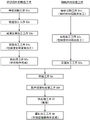
Fig. 3 is a block diagram showing a manufacturing process of the outer joint member of fig. 2.
Fig. 4a is a longitudinal sectional view of the cup-shaped member after ironing.
Fig. 4b is a longitudinal sectional view of the cup-shaped member after turning.
Fig. 5a is a front view of a bar material as a material of a shaft member.
FIG. 5b is a front view in partial cross-section after forging.
Fig. 5c is a partially cut-away front view of the shaft member after the turning and spline machining.
Fig. 6 is a schematic perspective view of the welding apparatus before welding.
Fig. 7 is a schematic elevation view of a welding apparatus in a welding process.
Fig. 8a is a schematic perspective view showing the entire appearance of the inspection apparatus.
Fig. 8b is a diagram for explaining an outline of main inspection items.
Fig. 9 is a schematic diagram showing a pulsation measurement by the contact displacement meter.
Fig. 10a is a schematic cross-sectional view showing an appearance inspection by a laser displacement meter.
Fig. 10b is a diagram showing an example of the inspection result.
Fig. 11a is a schematic cross-sectional view showing an inspection of a welded portion by an ultrasonic flaw detector.
Fig. 11b is an expanded view showing echo level data (criterion) corresponding to 1 cycle of the welding position.
Fig. 11c is an expanded view of the reflected echo measurement.
Fig. 12 is a diagram showing a list of the relationship between the examination items, examination results, and storage.
Fig. 13 is a schematic perspective view of the ultrasonic testing apparatus.
Fig. 14 is a schematic plan view of the ultrasonic testing apparatus.
Fig. 15 is a schematic perspective view of the ultrasonic testing apparatus.
Fig. 16 is a schematic plan view of the ultrasonic testing apparatus.
Fig. 17a is an enlarged partial cross-sectional view of the welded joint taken along line XVII-XVII in fig. 15.
Fig. 17b is an enlarged partial cross-sectional view of the welded blind taken along line XVII-XVII of fig. 15.
Fig. 18 is a partially enlarged sectional view similar to fig. 17 for explaining the view in the development process.
Fig. 19 is a partially cut-away front view showing shaft members different in number.
Fig. 20 is a partially cut-away front view of an outboard coupling member manufactured using the shaft member of fig. 19.
Fig. 21 is a block diagram for explaining an example of unifying the varieties of cup-shaped members.
Fig. 22a is a partially cut-away front view of an outer joint member of the second example.
Fig. 22b is an enlarged view of a portion b of fig. 22 a.
Fig. 22c is an enlarged view similar to fig. 22b showing a state before welding.
Fig. 23 is a longitudinal sectional view of the cup-shaped member in fig. 22 a.
Fig. 24 is a block diagram for explaining a second example of the method of manufacturing the outer joint member.
Fig. 25 is a block diagram for explaining a third example of the method of manufacturing the outer joint member.
Fig. 26 is a partially cut-away front view of a constant velocity universal joint showing a third example of an outer joint member.
Fig. 27 is a front view, in partial cross-section, of the outboard coupling member of fig. 26.
Fig. 28 is a longitudinal sectional view of an intermediate product for explaining a prior art outer joint member.
Fig. 29 is a longitudinal sectional view for explaining a prior art outer joint member.
Fig. 30 is a longitudinal sectional view for explaining another prior art outer joint member.
Detailed Description
Hereinafter, embodiments of the present invention will be described with reference to the drawings.
First, a first example of the outer joint member will be described with reference to fig. 1 and fig. 2a to 2c, and then a first example of a method of manufacturing the outer joint member will be described with reference to fig. 3 to 18.
Fig. 1 shows the overall structure of a drive shaft 1. The drive shaft 1 mainly includes a plunging type constant velocity universal joint 10, a fixed type constant velocity universal joint 20, and an intermediate shaft 2 that connects the two joints 10 and 20. The plunging constant velocity universal joint 10 is disposed on the differential side (the right side in the drawing: also referred to as the inner disc side), and the fixed constant velocity universal joint 20 is disposed on the drive wheel side (the left side in the drawing: also referred to as the outer disc side).
The plunging type constant velocity universal joint 10 is a so-called double-race type constant velocity universal joint (DOJ), and includes, as main components, an outer joint member 11, an inner joint member 16, a plurality of balls 41 as torque transmission elements, and a retainer 44 that retains the balls 41.
The outer joint member 11 includes a cup portion 12 and a long shaft portion (hereinafter also referred to as a long rod portion) 13 extending in the axial direction from the bottom of the cup portion 12. The inner joint member 16 is accommodated in the cup-shaped portion 12 of the outer joint member 11. Cup-like outer coupling member 11The track groove 30 formed in the inner periphery of the portion 12 and the track groove 40 formed in the outer periphery of the inner joint member 16 form a pair, and balls 41 are disposed between the respective pairs of track grooves 30, 40. The retainer 44 is positioned between the outer joint member 11 and the inner joint member 16, and contacts the partially cylindrical inner peripheral surface 42 of the outer joint member 11 at a spherical outer peripheral surface 45 and contacts the spherical outer peripheral surface 43 of the inner joint member 16 at a spherical inner peripheral surface 46. Center of curvature O of spherical outer peripheral surface 45 of retainer 441A center of curvature O with the spherical inner peripheral surface 462Are shifted at equal distances to the opposite side in the axial direction with respect to the joint center O.
An inner ring of the support bearing 6 is fixed to an outer peripheral surface of the long rod portion 13, and an outer ring of the support bearing 6 is fixed to the transmission case via a bracket, not shown. By supporting the outer joint member 11 by the support bearing 6 in a rotatable manner in this manner, vibration of the outer joint member 11 during operation and the like can be prevented as much as possible.
The fixed type constant velocity universal joint 20 is a so-called rzeppa type constant velocity universal joint, and includes, as main components, an outer joint member 21, an inner joint member 22, a plurality of balls 23 as torque transmission elements, and a retainer 24 that retains the balls 23. The outer joint member 21 has a bottomed cylindrical cup portion 21a and a shaft portion 21b extending in the axial direction from the bottom of the cup portion 21 a. The inner joint member 22 is accommodated in the cup portion 21a of the outer joint member 21. The balls 23 are disposed between the cup-shaped portion 21a of the outer joint member 21 and the inner joint member 22. The retainer is located between the inner peripheral surface of the cup-shaped portion 21a of the outer joint member 21 and the outer peripheral surface of the inner joint member 22.
As the fixed type constant velocity universal joint, an undercut free (constant velocity universal joint) type may be used.
The intermediate shaft 2 has a spline (including serrations, the same applies hereinafter) shaft 3 at both end portions thereof. The intermediate shaft 2 and the inner joint member 16 of the plunging constant velocity universal joint 10 are connected to each other so as to be able to transmit torque by inserting the spline shaft 3 on the inner disk side into the spline hole of the inner joint member 16 of the plunging constant velocity universal joint 10. The intermediate shaft 2 and the inner joint member 22 of the fixed constant velocity universal joint 20 are connected to each other so as to be capable of transmitting torque by inserting the spline shaft 3 on the outer disk side into the spline hole of the inner joint member 22 of the fixed constant velocity universal joint 20. Although an example of the solid intermediate shaft 2 is illustrated, a hollow type may be used.
Grease as a lubricant is sealed inside the constant velocity universal joints 10 and 20. Bellows-shaped boots 4 and 5 are respectively attached between the outer joint member 11 of the plunging constant velocity universal joint 10 and the intermediate shaft 2 and between the outer joint member 21 of the fixed constant velocity universal joint 20 and the intermediate shaft 2, thereby preventing leakage of grease and intrusion of foreign matter.
Next, the outer joint member 11 will be described in detail with reference to fig. 2.
As shown in fig. 2(a), the outer joint member 11 is composed of a cup portion 12 and a shaft portion (long rod portion) 13. The outer joint member 11 is manufactured by joining the cup-shaped member 12a and the shaft member 13a by butt welding, and the manufacturing process will be described in detail later.
Cup-shaped portion 12 has a bottomed cylindrical shape with one end open, and inner circumferential surface 42 has a plurality of track grooves 30 formed at equal intervals in the circumferential direction, and as a result, inner circumferential surface 42 is formed in a partial cylindrical shape. The balls 41 (see fig. 1) roll on the track grooves 30.
The cup-shaped member 12a forming the cup-shaped portion 12 is formed of medium carbon steel containing 0.40 to 0.60 wt% of carbon such as S53C, and is an integrally formed member composed of a cylindrical portion 12a1 and a bottom portion 12a 2. The cylindrical portion 12a1 is formed with the above-described track grooves 30 and the inner circumferential surface 42. A boot attachment groove 32 is formed in the outer periphery of the opening side of the cup-shaped member 12a, and a retainer groove 33 is formed in the inner periphery. The bottom portion 12a2 has a short-axis portion 12a3 as a solid axial shaft portion projecting toward the shaft member 13a, and the short-axis portion 12a3 has an end face 50 for engagement (fig. 2 c). The solid shaft shape is intended to exclude a case where a hollow portion penetrating in the axial direction is provided, and a case where a hollow portion extending in the axial direction from the joining end surface is provided (see patent documents 1 and 2). The cup-shaped member is a bottomed cylinder as a whole, but the short shaft portion 12a3 having the joining end face formed thereon has neither a through hole nor a hollow portion extending in the axial direction from the joining end face, and therefore at least the short shaft portion 12a3 has a solid shaft shape.
The joining end face 50 is machined by turning. Here, a shallow recess 50b is formed on the inner diameter side of the joining end face 50, and as a result, an annular joining end face 50 is formed on the outer diameter side of the recess 50 b. Symbol D indicates the inner diameter of the joining end surface 50. The recess 50b may be formed during forging or by cutting. By forming the recess 50b in the forging process, the number of man-hours is small, and the time required for turning can be shortened because the joining end surface 50 is annular.
The shaft portion 13 is a solid shaft extending in the axial direction from the bottom of the cup portion 12, and has a bearing attachment surface 14 and a retainer groove 15 formed near the outer periphery of the cup member 12a, and a spline shaft Sp as a torque transmission coupling portion formed at an end portion on the opposite side of the cup portion 12.
The shaft member 13a forming the shaft portion 13 is made of medium carbon steel containing 0.30 to 0.55 wt% of carbon, such as S40C, and a joining end surface 51 is formed at an end portion on the cup-shaped member 12a side (fig. 2C). The joining end surface 51 is provided with a recess 52 on the inner diameter side, and as a result, is formed into an annular surface. Symbol E represents the inner diameter of the joining end surface 51. Fig. 2 and 5 show an example in which the recess 52 is formed during forging and the inner diameter portion 53 is formed on the joining end face 51 by cutting, so that the recess 52 and the inner diameter portion 53 look like a stepped hole, and the inner diameter portion 53 is an inner diameter portion of the joining end face 51 or may be called an inner diameter portion of the recess 52. The recess 52 may be a forged surface as it is, in which case the inner diameter portion 53 clearly distinguishable from the recess 52 as shown in the drawing does not appear.
The recess 52 has a shallow bottom, i.e., is very shallow compared to the diameter of the joining end face 51, and the lower limit is about 1mm if the depth is exemplified. This is to secure a straight portion having an axial length necessary for ultrasonic flaw detection of a dimension (penetration depth) failure in the radial direction of the welded portion 49. The lower limit is a value from the surface of the ultrasonic flaw detection, and the depth of the recess 52 is desired from the viewpoint of reducing the volume in the vicinity of the joint portion to shorten the preheating time.
In the case of forming the depression during forging, the upper limit of the depth of the depression 52 is about a limit value (target) × 1.5mm that can be formed by forging. If the recess 52 is too deep, the forging load increases, the die life decreases, and the machining cost increases. Even when the recess 52 is formed by cutting, if the recess is too deep, the machining time becomes long, and the material yield also becomes poor.
The inner diameter portion 53 of the joining end surface 51 depends on the outer diameter of the shaft member 13a, but it is a prerequisite to secure the radial width of the welded portion 49 formed on the outer diameter side of the recess 52. The term "diameter" as an inner diameter is usually associated with a circular shape, but the contour of the inner diameter portion 53 as viewed in a plane perpendicular to the axis of the shaft member 13a is not necessarily limited to a circular shape, and may be, for example, a polygonal shape or an irregular shape.
Welding is performed by abutting a joining end surface 50 of the cup-shaped member 12a with a joining end surface 51 of the shaft member 13a and irradiating electron beams from the outside of the cup-shaped member 12a in the radial direction (fig. 2a and 2 b). As described above, the welded portion 49 is formed of the molten metal that is melted and solidified during welding and the heat affected zone around the molten metal.
As will be described in detail later, the outer diameters B (see fig. 4B and 5c) of the joining end surfaces 50 and 51 are set to the same size for each coupling size. However, the outer diameter B of the joining end surface 50 of the cup-shaped member 12a and the outer diameter B of the joining end surface 51 of the shaft member 13a are not necessarily the same size. For example, an appropriate dimensional difference such as a slightly smaller outer diameter B of the joining end surface 51 than the outer diameter B of the joining end surface 50 may be added in consideration of the state of the weld bead. The dimensional relationship between the outer diameter B of the joining end face 50 and the outer diameter B of the joining end face 51 is the same in this specification.
Since the welded portion 49 is formed on the cup-shaped member 12a side of the shaft member 13a with respect to the bearing attachment surface 14, the bearing attachment surface 14 and the like can be processed in advance before welding, and thus, post-processing after welding can be eliminated. In addition, since no burr is generated in the welded portion for the electron beam welding, the post-processing of the welded portion can be omitted in this respect as well, the manufacturing cost can be reduced, and the entire inspection by the ultrasonic flaw detection of the welded portion can be realized.
As shown in fig. 2c, the inner diameter D of the joining end surface 50 of the cup-shaped member 12a is set smaller than the inner diameter E of the inner diameter portion 53 of the joining end surface 51 of the shaft member 13 a. In other words, the recess 50b is smaller in diameter than the recess 52. As a result, the joining end surface 50 of the cup-shaped member 12a partially protrudes radially inward from the joining end surface 51 of the inner diameter E. The protruding portion is referred to as a protruding surface 50 a. The joining end surfaces 50 and 51 having such shapes are butted against each other, and the cup-shaped member 12a and the shaft member 13a are joined by welding. The projecting surface 50a is set to be the same for each coupling size.
Next, a method of manufacturing the outer joint member will be described with reference to fig. 3 to 18. The overall manufacturing process will be described before the respective manufacturing processes are described in detail.
As shown in fig. 3, the cup-shaped member 12a is manufactured through manufacturing processes including a bar cutting process S1c, a forging process S2c, a ironing process S3c, and a turning process S4 c.
On the other hand, the shaft member 13a is manufactured through manufacturing processes including a bar cutting process S1S, a turning process S2S, and a spline machining process S3S.
The cup-shaped member 12a and the shaft member 13a thus manufactured are respectively managed by numbering. Then, the cup-shaped member 12a and the shaft member 13a are subjected to welding step S6, ultrasonic testing step S6k, heat treatment step S7, and grinding step S8 to complete the outer joint member 11.
The outline of each step is as follows. The steps described herein are representative examples of the steps, and can be appropriately changed and added as necessary.
First, a manufacturing process of the cup-shaped member 12a will be described.
[ Bar Material cutting Process S1c ]
A bar material (round bar) is cut into a predetermined length according to the forging weight to produce a columnar billet.
[ forging Process S2c ]
The cylindrical portion, the bottom portion, and the convex portion as a blank of the cup-shaped member 12a are integrally formed by forging a billet.
[ ironing Process S3c ]
The rolling groove 30 and the cylindrical surface 42 of the blank are subjected to ironing, thereby completing the inner periphery of the cylindrical portion of the cup-shaped member 12 a.
[ turning Process S4c ]
The blank after the ironing is turned into an outer peripheral surface, a boot mounting groove 32, a retainer groove 33, and the like, and a joining end surface 50. The cup-shaped member 12a as the intermediate member having undergone the turning process S4c is managed by reference numerals.
Next, a manufacturing process of the shaft member 13a will be described.
[ Bar Material cutting Process S1S ]
The rod material is cut to a predetermined length according to the entire length of the shaft portion, thereby producing a columnar billet. Thereafter, depending on the shape of the shaft member 13a, the billet may be forged to a rough shape by upsetting.
[ turning Process S2S ]
The outer peripheral surface of the billet (bearing mounting surface 14, retainer groove 15, spline lower diameter, end surface, etc.) and the joining end surface 51 of the end portion of the cup-shaped member 12a are subjected to turning.
[ spline processing step S3S ]
The spline shaft is formed by roll-forming a spline on the shaft member after the turning. However, the spline machining is not limited to the rolling machining, and may be replaced with a press machining or the like as appropriate. The shaft member 13a as the intermediate member subjected to spline machining is managed by reference numerals.
Next, the manufacturing process from the cup-shaped member 12a and the shaft member 13a, which are the intermediate members obtained as described above, to the completion of the outer joint member 11 will be described.
[ welding Process S6]
The joining end surface 50 of the cup-shaped member 12a and the joining end surface 51 of the shaft member 13a are butted and welded. The welding step will be described in detail later.
[ ultrasonic testing Process S6k ]
The welded portion 49 between the cup-shaped member 12a and the shaft member 13a is inspected by ultrasonic flaw detection. The ultrasonic flaw detection step will be described in detail later.
[ Heat treatment Process S7]
Heat treatment for induction quenching and tempering is performed on at least a required range of the track groove 30, the inner peripheral surface 42, and the outer periphery of the shaft member 13 of the cup-shaped portion 12 after welding. The welded portion 49 is not heat-treated. By the heat treatment, hardened layers of about HRC 58-62 are formed on the raceway groove 30 and the inner peripheral surface 42 of the cup portion 12. Further, a hardened layer of about HRC 50-62 is formed in a predetermined range on the outer periphery of the shaft portion 13.
[ grinding Process S8]
After the heat treatment, the bearing mounting surface 14 of the shaft member 13 and the like are ground and finished. Thereby, the outer joint member 11 is completed.
Since the heat treatment step is added after the welding step, the cup-shaped member and the shaft member are suitable for the case of shapes and specifications in which the temperature of the peripheral portion is increased by the heat at the time of welding and the hardness of the heat treated portion is affected.
The main structure of the above-described method for manufacturing the outer joint member will be described in further detail.
Fig. 4a shows the cup-shaped member 12a after the ironing process, and fig. 4b shows the cup-shaped member after the turning process. The blank of the cup-shaped member 12a is integrally formed with the cylindrical portion 12a1 ', the bottom portion 12a2 ', and the stub shaft portion 12a3 ' in the forging step S2 c. Thereafter, in the ironing step S3c, the track grooves 30 and the cylindrical surface 42 are ironed, and the inner periphery of the cylindrical portion 12a 1' is finished as shown in fig. 4 a. Then, in the turning step S4c, as shown in fig. 4B, the outer peripheral surface of the cup-shaped member 12a, the attachment end surface 50 of the boot attachment groove 32, the retainer groove 33, and the like, and the short shaft portion 12a3, and the outer diameter B and the inner diameter D of the attachment end surface 50 are turned.
Fig. 5a to 5c show the state of the shaft member 13a in each machining step. That is, fig. 5a shows a billet 13a obtained by cutting a bar material, fig. 5b shows a billet 13a "forged into a rough shape by upsetting, and fig. 5c shows a shaft member 13a obtained by turning and spline machining.
In the bar cutting step S1S, a billet 13a ″ shown in fig. 5a is produced. As shown in fig. 5b, the billet 13a ″ is subjected to upsetting as necessary to produce a blank 13 a' having a diameter expanded by a predetermined range and a recess 52 formed in the joint-side end (the end on the cup-shaped member 12 a).
Thereafter, in the turning step S2S, as shown in fig. 5c, the outer diameter of the shaft member 13a, the bearing mounting surface 14, the retainer groove 15, the inner diameter portion 53 (inner diameter E), the joining end surface 51, and the outer diameter B thereof are turned. In the spline machining step S3S, the spline shaft Sp is machined by rolling or pressing at the opposite end of the recess 52.
The outer diameter B of the joining end surface 50 of the cup-shaped member 12a shown in fig. 4B is set to the same size in one coupling size. The shaft member 13a shown in fig. 5c is of a long rod type, but the outer diameter B of the joining end surface 51 at the end of the cup-shaped member 12a is set to the same size as the outer diameter B of the joining end surface 50 of the cup-shaped member 12a, regardless of the shaft diameter and the outer peripheral shape. The joining end surface 51 of the shaft member 13a is set at a position closer to the cup-shaped member 12a than the bearing mounting surface 14.
Since the cup-shaped member 12a is set to have the same size as the vehicle body, the outer joint member 11 suitable for various vehicle types can be manufactured by simply forming the shaft member 13a into various shaft diameters, lengths, and outer peripheral shapes corresponding to the vehicle types and welding the two members 12a and 13 a. Details of the sharing of the cup-shaped member 12a will be described later.
Next, welding of the cup-shaped member 12a and the shaft member 13a will be described with reference to fig. 6 and 7. Fig. 6 and 7 are a schematic elevational view and a schematic plan view showing the welding apparatus, fig. 6 shows a state before welding, and fig. 7 shows a welding process.
As shown in fig. 6, the welding apparatus 100 includes, as main components, an electron gun 101, a rotating apparatus 102, a chuck 103, a center 104, a tailstock 105, a workpiece stage 106, a center 107, a housing 108, and a vacuum pump 109.
Cup-shaped member 12a and shaft member 13a as a workpiece are mounted on workpiece mounting table 106 in welding apparatus 100. A chuck 103 and a centering jig 107 located at one end of the welding apparatus 100 are connected to the rotating apparatus 102. In a state where the cup-shaped member 12a is centered by the center 107, the cup-shaped member 12a is held by the chuck 103 and is given a rotational motion by the rotating device 102. A center 104 is integrally attached to a tail stock 105 located at the other end of the welding apparatus 100, and both are configured to be able to advance and retreat in the axial direction (the left-right direction in fig. 6).
Centering is performed by fitting the center hole of the shaft member 13a to the center piece 104. A vacuum pump 109 is connected to a casing 108 of the welding apparatus 100. Here, the closed space is a space 111 formed by the housing 108, and the cup-shaped member 12a and the shaft member 13a are entirely housed in the closed space 111. An electron gun 101 is provided at a position corresponding to the joining end surfaces 50, 51 of the cup-shaped member 12a and the shaft member 13 a. The electron gun 101 can approach and separate from the workpiece.
The operation and welding method of the welding apparatus 100 with respect to the above-described structure are as follows.
The cup-shaped member 12a and the shaft member 13a as the workpieces are stored in a place different from the welding apparatus 100. For example, each workpiece is taken out by a robot, transported into a housing 108 of the welding apparatus 100 which is open to the atmosphere as shown in fig. 6, and placed at a predetermined position on the workpiece mounting table 106. At this time, the center piece 104 and the tailstock 105 are retracted to the right in the figure, and a gap is present between the joining end surfaces 50 and 51 of the cup-shaped member 12a and the shaft member 13 a.
Thereafter, a door (not shown) of the casing 108 is closed, and the vacuum pump 109 is started to reduce the pressure in the sealed space 111 formed in the casing 108. Thereby, the inside of the recess 50b of the cup-shaped member 12a and the recesses 52 and 53 of the shaft member 13a are also decompressed.
When the sealed space 111 is depressurized to a predetermined pressure, the center piece 104 and the tail stock 105 move leftward as shown in fig. 7, and the gap between the joining end surfaces 50 and 51 of the cup-shaped member 12a and the shaft member 13a disappears. Thereby, the cup-shaped member 12a is centered by the center 107 and fixed by the chuck 103, and the shaft member 13a is centered by the center 104 and supported. Thereafter, the workpiece mounting table 106 is separated from the workpieces (12a, 13 a). In this case, the distance between the workpiece mounting table 106 and the workpieces (12a, 13a) may be a minute distance, and therefore, the distance is not shown in fig. 7. Of course, the work mounting table 106 may be retracted downward to a large extent.
Thereafter, although not shown, the electron gun 101 is moved to a predetermined position to be close to the workpieces (12a, 13a), and the workpieces (12a, 13a) are rotated to start preheating. The preheating condition is different from the welding condition, and is a temperature lower than the welding temperature by irradiating an electron beam or the like so as to be larger than the beam size at the time of welding. The preheating increases the amount of heat input, and the subsequent heating described later is combined with the heat input, so that the cooling rate of the welded portion after welding is reduced, and as a result, the hardening crack can be prevented.
After a predetermined warm-up time is reached, the electron gun 101 is retracted to a predetermined position, and welding is started by irradiating the workpieces (12a, 13a) with electron beams in the radial direction from the outside. The workpieces (12a, 13a) are welded over the entire circumference during one rotation, and an annular welded portion 49 is formed.
In order to slow down the cooling rate of the welded portion 49 and prevent the occurrence of quench cracking, post-heating is performed.
When welding is completed, the electron gun 101 is retracted and rotation of the workpieces (12a, 13a) is stopped.
After that, although not shown, the sealed space 111 is opened to the atmosphere. Then, the workpiece stage 106 is raised, and in a state of supporting the workpiece, the center piece 104 and the tailstock 105 are retracted to the right side of the drawing, and the chuck 103 is opened. Thereafter, for example, the robot holds the workpieces (12a, 13a), takes out the workpieces from the welding apparatus 100, and arranges the workpieces in the cooling stocker. In the present embodiment, since the cup-shaped member 12a and the shaft member 13a are integrally housed in the sealed space 111, the structure of the sealed space 111 in the housing 108 can be simplified.
If specific conditions for welding are exemplified, the following is described.
A cup-shaped member 12a containing 0.4 to 0.6 wt% of carbon and a shaft member 13a containing 0.3 to 0.55 wt% of carbon are used, and welding is performed in a welding apparatus 100 with the pressure of a sealed space 111 in a housing 108 set to 6.7Pa or less. In order to prevent rapid cooling after welding and avoid excessive hardness of the welded portion, the periphery of the joining end faces 50, 51 including the cup-shaped member 12a and the shaft member 13a is subjected to electron beam welding after being heated to 300 to 650 ℃ by preheating with an electron beam. As a result, compared with the case where no recess is provided on the inner diameter side of the joining end face, the preheating time can be shortened to about 1/2 or less, and a good welded portion satisfying the required strength can be obtained.
As a result, a welded portion having a height of a projection (0.5mm or less) of the welded surface which does not affect the product function can be obtained. Further, since the heat is equalized by the preheating, the hardness of the welded portion after the end of welding can be suppressed within the range of HV200 to 500, the welding strength is high, and a stable welding state and quality can be obtained. Further, by welding the sealed space 111 of the welding apparatus 100 at atmospheric pressure or less, pressure changes in the recess 52 and the recess 50b during welding can be suppressed, and the molten material can be prevented from flowing out and being introduced into the inner diameter side.
The welded work, i.e., the joint type outer joint member 11, is sent to the inspection apparatus. Each inspection process will be described below with reference to fig. 8 showing a schematic configuration of the inspection apparatus. The order of the inspection steps and the arrangement of the inspection units serving as the respective inspection steps are not limited to the illustrated examples, and may be arbitrarily changed, and the specific configuration of each inspection unit may be changed as appropriate depending on, for example, whether or not the rotary drive mechanism is shared or other conditions.
The entire inspection apparatus 80 illustrated in fig. 8 is surrounded by a casing, and a cooling section I, a dewatering section II, a surface inspection section III, and an internal inspection section IV are arranged in this order from the right side to the left side in fig. 8. A robot 90 for transferring the workpiece W is provided in the vicinity of each of the sections I to IV. Then, as indicated by white arrows, the workpieces W having completed the welding process are first put into the cooling section I, and all the workpieces W having completed the inspection are carried out and sent to the next process. The workpiece W determined as defective as a result of the inspection is excluded from the production line and collected in a predetermined place.
Although not shown, the contact gauge, the laser displacement gauge, and the ultrasonic flaw detector constituting the inspection device 80 are electrically connected to a control device provided outside the housing via an interface. Generally, the control device corresponds to a main machine of the manufacturing line. The control device is provided with a recording unit capable of recording inspection results including inspection items, measurement values, and the like for each workpiece in association with the workpiece number. The data of the recording unit can be displayed on a display on the operation panel, and the inspection result can be confirmed even on site (see fig. 10b and 11 c).
The cooling section I is a section for performing a cooling process. That is, a cooling water tank 82 is provided, and the high-temperature workpiece W after welding is immersed in the cooling water tank 82 and cooled. In general, the subsequent step is cooled to room temperature so as not to hinder the conveyance.
The workpiece having completed the cooling process is sent to the dehydration unit II. The dehydration section II is provided with a dehydration device 84 for dispersing excess water by blowing air to the work taken out from the cooling water tank 82.
The workpiece having completed the dehydration step is sent to the surface inspecting section III. In the surface inspection section III, measurement of a defect occurring on the surface of the workpiece, that is, a run-out of the workpiece and detection of a crater on the bead surface of the weld 49 are performed. Since the inspection and measurement are performed over the entire circumference of the workpiece while rotating the workpiece, the same rotary drive mechanism is used in the surface inspection unit III, but it is needless to say that pit detection and run-out measurement may be performed separately at different places. The rotation driving mechanism is advantageously a servomotor with an encoder, so that the rotation angle of the workpiece and each measured value can be recorded in association with each other.
As shown in fig. 8b (1) and 9, the jitter measurement is performed using a contact gauge 86 a. In an embodiment, an electrical dial indicator is used as the contact gauge 18 a. The runout is measured over the entire circumference while rotating the workpiece W. The measurement value is transmitted as an electronic signal from the contact gauge 86a to the recording unit, and the measurement value is recorded in the recording unit in association with the rotation of the workpiece W, so that a 360 ° jump line graph can be obtained. The jitter measurement value is recorded in the recording unit for each workpiece W in association with the workpiece number. Then, the maximum value of the measurement values is compared with a preset upper limit value, and a workpiece W whose maximum value exceeds the upper limit value is determined to be defective.
Since the workpiece W is a long rod-shaped outer joint member 11 and has a long dimension, the axial measurement position is measured for a plurality of points, at least for the cup-shaped member 12a and the shaft member 13 a. As shown in fig. 9, when the shaft portion 13 has surfaces that have been ground, such as the bearing attachment surface 14 and the boot attachment surface 16, at both ends thereof, these surfaces can be used as measurement surfaces.
As shown in fig. 8b (2) and fig. 10a, the detection of the pits is performed using a laser displacement meter 86 b. For example, a reflection-type laser displacement meter is known that includes a light projection unit for projecting laser light onto a measurement object and a light reception unit for receiving the laser light reflected by the measurement object. The laser light emitted from the laser light emitter is reflected by the object to be measured and received by the laser light receiver, and a spot is formed on the laser light receiver. Since the spot moves every time the object moves, the position of the spot is detected to detect the amount of displacement to the object. Here, the presence or absence of the pit is detected by non-contact by irradiating the welding portion 49 with a laser beam while rotating the work W, and the depth thereof is measured.
Fig. 10b is a diagram illustrating an image on the display of the operation panel in the case where a pit having a depth h of about 0.4mm is detected, in which the horizontal axis indicates the bead width direction of the welded portion 49 and the vertical axis indicates the radial direction of the welded portion 49. The measurement result of the laser displacement meter 86b is transmitted as an electronic signal from the laser displacement meter 86b to the recording unit, and the maximum value of the depth h when the workpiece is rotated once is recorded in the recording unit in association with the number of the workpiece W. Then, the measured value of the depth h is compared with a preset upper limit value, and a workpiece W whose measured value exceeds the upper limit value is determined to be defective.
The workpiece having completed the runout measurement and pit detection processes is sent to the internal inspection unit IV. As shown in fig. 11, the internal inspection section IV detects an internal defect of the welded portion 49, that is, a penetration defect of the welded portion 49 (see fig. 8b (3)), and detects a blowhole and a weld crack (see fig. 8b (4)) by using an ultrasonic flaw detector. As shown by the two-dot chain line in fig. 11a, the probe 147 of the ultrasonic flaw detection apparatus 120 is scanned in the axial direction, and a penetration defect, a blowhole, and a weld crack are detected based on the echo height of the reflected echo with respect to the incident pulse G from the probe 147. Fig. 11b shows echo level data (criterion) corresponding to 1 week of the welding position, and fig. 11c shows an example of a case where the echo level does not reach the criterion. The ultrasonic flaw detection performed by the ultrasonic flaw detection apparatus 120 will be described in further detail later. The measurement results of the ultrasonic flaw detector 120 are transmitted as electronic signals to the recording unit, and when the presence or absence of a defect such as a weld penetration defect, a blowhole, or a weld crack or a defect is detected in the recording unit, the axial and circumferential positions of the defect are recorded for each workpiece W in association with the workpiece number. Then, the workpiece W in which these defects are detected is determined to be defective.
In the welding step, which is a pre-step of the inspection, the monitoring width is set with respect to the degree of vacuum, preheating of welding, and post-heating condition, and the completion of the processing is confirmed under appropriate conditions, and the result is recorded in the recording unit of the inspection apparatus 80. At this time, as a series of production lines, the machining conditions and the inspection results are recorded in association with the workpiece numbers, and traceability is secured. The number of the work may include, in addition to the type of welding, identification of the base material (cup-shaped member, shaft member), confirmation of the welding position, confirmation of the cause and the subject of the nondestructive test, and the like.
Fig. 12 illustrates a list of records on inspection results and the like and storage of data, wherein ○ in the "record content" column indicates that the item should be recorded, that is, in the "item" column, "an execution model number" indicates the number of a workpiece and is recorded in the "set value" column, at the "inspection completion time," an actual time is recorded in the "actual measurement value" column, "in the" pit, "an upper limit and a lower limit are recorded in the" set value "column, and an" actual measurement value "and a" determination result "are recorded in the" penetration defect "column," in the "vacuum degree and welding condition," in the "set value" column, an upper limit and a lower limit are recorded, in the "jump measurement," in the "cup side" and the "rod side," in the "set value" column, respectively, an "actual measurement value" and a "determination result" are recorded, in the "internal defect (detailed data" column, "in the" set value "and" in the "actual measurement result" storage of the "in the" internal defect (detailed flaw detection line, "in the" inspection line, "in which all pieces of the data are recorded in the" inspection line inspection results, and the "flaw detection data" in the host inspection line, "in which the inspection results, and the ultrasonic flaw detection data are recorded in the" inspection device.
Next, the ultrasonic flaw detection process will be described with reference to fig. 13 to 18.
Fig. 13 and 14 are a front view and a plan view of the ultrasonic testing apparatus on which the welded outer joint member is mounted, and fig. 13 corresponds to a view from XIII to XIII in fig. 14. Fig. 15 and 16 are a front view and a plan view of the ultrasonic testing apparatus in ultrasonic flaw detection, and fig. 15 corresponds to an XV-XV view of fig. 16.
As shown in fig. 13 and 14, the ultrasonic testing apparatus 120 includes a base 121, a water storage tank 122, a workpiece mounting table 123, a workpiece pressing member 124, a rotation driving device 125, a pressing device 135, and a drive positioning device 136 (see fig. 14). The water storage tank 122 is provided in the center of the base 121. The rotary drive device 125 is a device for rotating the workpiece W, i.e., the welded outer joint member 11. The pressing device 135 is a device for pressing the shaft end portion of the workpiece W. The drive positioning device 136 performs the driving and positioning of the probe.
The workpiece mounting table 123 includes support rollers 126 and 127 for rotatably mounting the workpiece W thereon, the support roller 126 is disposed at a position close to the welded portion, and the support roller 127 is disposed near the center of the shaft portion 13. As is apparent from fig. 14, each of the support rollers 126 and 127 is formed of a pair of rollers spaced on both sides of the axis of the shaft portion 13 so as to stably support the shaft portion 13 of the workpiece W. The support rollers 126 and 127 can appropriately adjust the installation positions of the workpiece W in the axial direction (the left-right direction in fig. 13) and the radial direction (the vertical direction in fig. 13) in consideration of the coupling dimension, the dimension, and the weight balance of the workpiece W.
In addition, in the plan view of fig. 14, a workpiece pressing member 124 is provided at a position of the workpiece stage 123 offset from the axis of the workpiece W. The workpiece pressing member 124 has a lever 128, and a workpiece pressing roller 129 is provided at an end of the lever 128. The control lever 128 is rotatable in the plane of fig. 14 and movable in the up-down direction of fig. 13.
The workpiece stage 123 is mounted on a support base 134 via a linear motion bearing 130 including a rail 131 and a linear guide 132, and is movable in the axial direction (the left-right direction in fig. 13 and 14). The support base 134 is attached to the base 121. The workpiece mounting table 123 can be positioned at a desired position by being moved by an actuator (not shown) disposed outside the water storage tank 122 via a rod 133 connected to an end portion (left end portion in fig. 13 and 14).
The rotation driving device 125 has a rotation shaft 143 provided with a rotation plate 144, and the rotation shaft 143 is driven to rotate by a motor (not shown) disposed outside the water storage tank 122.
A stage 137 is provided above the ultrasonic testing apparatus 120, and a substrate 145 of the pressing device 135 is movably mounted on the stage 137 in the axial direction (the left-right direction in fig. 13 and 14) via a linear motion bearing 138 including a rail 139 and a linear guide 140. A piston rod 142 of an air cylinder 141 is connected to an end of the substrate 145, and the substrate 145 is driven by the air cylinder 141, i.e., the substrate 145 moves in the axial direction. The pressing device 135 is in contact with the shaft end of the shaft portion 13 of the workpiece W via a free bearing 146.
In the plan view of fig. 14, a drive device 136 for the probe is disposed at a position offset from the axis of the workpiece W. The driving device 136 is composed of actuators in the X-axis direction and the Y-axis direction, and moves and positions the probe 147 in the X-axis direction and the Y-axis direction. The X-axis actuator 148 and the Y-axis actuator 149 are electric ball screw type actuators (automatic cylinders), and can perform positioning with high accuracy. Reference numeral 150 denotes a track of the linear motion bearing. Drive unit 136 is disposed outside reservoir 122, and probe 147 and part of holder 151 are disposed within reservoir 122.
The operation of the ultrasonic flaw detection apparatus 120 and the ultrasonic flaw detection step S6k configured as described above will be described below.
First, the welded workpiece W is placed on the workpiece mounting table 123 by a loader (not shown) (see fig. 13 and 14). At this time, the workpiece stage 123 is located at a position spaced apart from the rotation driving device 125 by an appropriate distance in the axial direction of the workpiece W, and the workpiece pressing member 124 rotates the control lever 128 to a position substantially parallel to the axis of the workpiece W while being lifted. The pressing device 135 and the probe driving device 136 are on standby at the retracted position.
Then, the control lever 128 of the workpiece pressing member 124 is lowered while being rotated substantially at right angles to the axis of the workpiece W', and presses the workpiece W from above (see fig. 15). Here, water is supplied to the water storage tank 122. In this way, since the ultrasonic flaw detector 120 is configured to detect flaws in water, the propagation of ultrasonic waves is good and high-precision inspection can be achieved.
Next, as shown in fig. 15 and 16, the pressing device 135 is advanced by the operation of the air cylinder 141 to press the axial end of the workpiece W, and the open end of the cup-shaped portion 12 of the workpiece W is brought into contact with the rotating plate 144 of the rotation driving device 125. The workpiece stage 123 moves toward the rotary drive device 125 while the pressing device 135 moves forward. Thereby, the workpiece W is positioned in the axial direction and the radial direction. In this state, a motor (not shown) of the rotation driving device 125 is started to rotate the workpiece W.
As indicated by the open arrows in fig. 16, the drive device 136 moves in the X-axis direction and then in the Y-axis direction, thereby positioning the probe 147 at the flaw detection position. The probe 147 at this time is shown by a broken line in fig. 15. Then, ultrasonic flaw detection was performed. When the ultrasonic testing is completed, the inside of the water tank 122 is drained, and the workpiece W is carried out of the ultrasonic testing apparatus 120 by a loader (not shown). In this way, the ultrasonic flaw detection of the workpiece W is sequentially repeated.
In order to shorten the cycle time of ultrasonic flaw detection, it is desirable that water supply and water discharge which take time be performed at a timing interlocked with simultaneous operations of the devices and members. Further, the operations of the respective devices and members may be partially performed simultaneously or partially in a different order.
Details of the ultrasonic flaw detection will be described with reference to fig. 17a, 17b, and 18. These figures correspond to the view from XVII to XVII in fig. 10, with fig. 17a showing a welded-in part and fig. 17b showing a welded-out part. Fig. 18 is a diagram for explaining the insight obtained in the development process.
The probe 147 is positioned at a flaw detection position at a predetermined distance from the welded portion 49. The flaw detection position is set in advance for each coupling size. The transmission pulse G from the probe 147 is obliquely incident from the surface of the workpiece W, and the received reflected echo is displayed in a waveform, and the presence or absence of a defect can be determined by observing the waveform (oblique flaw detection method). Symbol θ 1 denotes an incident angle, and symbol θ 2 denotes a refraction angle. In the case of the embodiment, the incident angle θ 1 is about 0 to 30 °, the refraction angle θ 2 is about 0 to 90 °, and an angle corresponding to the position and shape of the inspection object can be appropriately selected.
As described above, the ultrasonic flaw detector 120 performs the inspection of the penetration defect (see (3) of fig. 8b) and the inspection of the blowholes and the weld cracks (see (4) of fig. 8b), but the latter inspection is the same as the ultrasonic flaw detection of the normal weld zone. Therefore, the former inspection will be mainly described here.
The penetration depth is used to determine whether the weld zone 49 has a penetration defect. That is, a member having a penetration depth exceeding the determination criterion Wmin and reaching the inner diameter side is a welded acceptable member, and a member having a penetration depth ending on the outer diameter side of the determination criterion Wmin is a welded unacceptable member. In the illustrated example, the inner diameter portion 53 of the recess 52 provided in the joining end face 51 is made to coincide with the determination criterion Wmin. Symbol E represents the inner diameter of (the inner diameter portion 53 of) the recess 52, but may be the inner diameter of the joining end surface 51. The symbol Wa represents the penetration of the target. Incidentally, after welding, the welded portion 49 is formed on the outer diameter side of the recess 52, and as a result, a closed cavity is formed on the inner diameter side of the welded portion 49. Therefore, the penetration bead 49a cannot be visually recognized from the outside.
During ultrasonic testing, the workpiece W is driven to rotate by the rotation driving device 125. The probe 147 positioned at the flaw detection position at a predetermined distance from the welded portion 49 collects data of the entire circumference of the workpiece W. Since the welding position corresponds to the tolerance deviation, at the above flaw detection position, data is acquired for one rotation (360 °) of the workpiece W, and then data is acquired for a plurality of rotations (for example, 5 rotations) by sequentially scanning in the axial direction at a minute pitch (for example, 0.5 mm). The quality is determined based on the data, and the threshold value of the reflected echo for quality determination is determined using the welding standard of the determination criterion Wmin.
As described above, the joining end surface 50 of the cup-shaped member 12a is provided with the protruding surface 50a protruding radially inward from the inner diameter E of the joining end surface 51 of the shaft member 13a, and according to this shape, the following advantage of ultrasonic testing can be obtained.
In order to easily understand the advantage, a description will be given of a finding obtained in the development process, that is, a case where the inner diameter D' of the joining end surface 50 of the cup-shaped member 12a and the inner diameter E of the joining end surface 51 of the shaft member 13a are made to have the same size as shown in fig. 18. In this case, the penetration depth exceeds the determination criterion Wmin and reaches the inner diameter side, and therefore it should be possible to determine a welded acceptable piece. However, when the transmission pulse G is incident from the probe 147, a boundary surface in a direction perpendicular to the transmission pulse G exists in the penetration bead 49a, and therefore, the probe 147 receives the reflected echo R reflected by the boundary surface. Although the reflected echo of the penetration bead 49a is scattered, the echo height of the reflected echo R is high, and therefore, the threshold value of the reflected echo for the non-acceptance determination is exceeded, and it is determined as a welding-unacceptable piece. In such a case, it is difficult to determine whether the welded acceptable piece or the welded unacceptable piece is welded.
Therefore, in the embodiment, a countermeasure is taken by providing the joining end surface 50 of the cup-shaped member 12a with a protruding surface 50a that protrudes radially inward from the inner diameter E of the joining end surface 51 of the shaft member 13 a.
The weld pass is deep enough to fuse as shown in fig. 17 a. In this case, the transmission pulse G from the probe 147 enters the cup portion 12 from the penetration bead 49a that has reached the inner diameter side beyond the determination criterion Wmin, and travels straight directly or is reflected by the inner diameter D of the cup portion 12 to travel toward the cup portion 12. Therefore, the probe 147 does not receive the reflected echo. That is, even if the transmission pulse G is incident on the penetration bead 49a, since there is a boundary surface of the penetration bead 49a in the direction perpendicular to the transmission pulse G, a reflected echo is generated which is scattered a little bit, but a reflected echo is not generated to such an extent that it causes erroneous detection. Therefore, the echo height of the reflected echo received by the probe 147 is equal to or less than the threshold value, and it is determined as a welding-acceptable piece.
By providing the protruding surface 50a on the joining end surface 50 of the cup-shaped member 12a in this way, the echo height of the reflected echo is reduced, and the accuracy of the inspection can be improved.
When a defective welding is performed, as shown in fig. 17b, the end of the weld bead 49a does not reach the determination criterion Wmin due to the penetration failure, and therefore, the transmission pulse G is reflected by the joining end face 51 and the chamfered portion 51a, and the probe 147 receives the reflected echo R that has been scattered. If the reflected echo R exceeds the threshold value of the reflected echo determined as acceptable, it is determined as an unacceptable welding part.
By providing the protruding surface 50a on the joining end surface 50 in this manner, the echo height of the reflected echo can be clearly distinguished, and the determination of the welded acceptable piece or the unacceptable piece can be performed with high accuracy.
As shown in fig. 17a, the dimension of the projection surface 50a is S ≧ Q when the width of the projection surface 50a in the radial direction is [ S-D)/2 ] and the height of the penetration bead 49a from the inner diameter E of the joining end surface 51 is Q. If this relationship is satisfied, the heights of the reflected echoes can be clearly distinguished, and a welded acceptable piece and an unacceptable piece can be determined with high accuracy. The dimension of the projection surface 50a can be set appropriately while maintaining the relationship of S.gtoreq. The inner diameter E of the joining end surface 51 may be (the inner diameter portion 53 of) the recess 52.
The ultrasonic flaw detection device 120 can interlock operations from the carrying-in of the workpiece W to the water supply, the water discharge, the ultrasonic flaw detection, and the carrying-out of the workpiece, and can automate the ultrasonic flaw detection. Therefore, the precision, workability, and efficiency of the inspection can be improved, and the inspection method is suitable for inspecting the welded portion of the outer joint member of the constant velocity universal joint as a mass product.
In addition, in the ultrasonic flaw detection, in combination with the configuration in which the outer diameter B of the joining end surface 50 of the cup-shaped member 12a is set to the same size for each joint size, the replacement adjustment work for the outer joint members 11 having different numbers can be reduced, and the detection efficiency can be further improved.
Further, since the structure is for performing flaw detection in water, the propagation of ultrasonic waves is good, and inspection with higher accuracy can be realized. Further, since the shape of the welded portion in which the protruding surface 50a is provided on the joining end surface 50 is adopted, the echo height of the reflected echo can be clearly distinguished, and the welded acceptable piece and the welded unacceptable piece can be determined with high accuracy.
Next, a supplementary explanation will be given by exemplifying shaft members having different numbers from the long rod type shaft member 13a shown in fig. 5, with respect to the variety of cup-shaped members.
The shaft member 13b shown in fig. 19 and 20 is for a standard lever on the inner disk side. The shaft member 13b has a joining end surface 51 that abuts against the joining end surface 50 (see fig. 4b) of the bottom portion 12a2 (stub shaft portion 12a3) of the cup-shaped member 12 a. The outer diameter B and the inner diameter E of the joining end surface 51 are formed to have the same dimensions as the outer diameter B and the inner diameter E of the joining end surface 51 of the long rod-type shaft member 13a shown in fig. 5.
Here, the inner diameter D of the joining end surface 50 of the cup-shaped member 12a is also set smaller than the inner diameter E of the joining end surface 51 of the shaft member 13 b. As a result, a projection surface 50a that projects radially inward from the inner diameter E of the joining end surface 51 of the shaft member 13b is formed on the joining end surface 50 of the cup-shaped member 12 a. The joining end surfaces 50 and 51 having such shapes are butted and welded to each other, whereby the cup-shaped member 12a and the shaft member 13b are joined.
Since the shaft member 13b is for a standard lever on the inner disk side, the shaft portion has a short length, a sliding bearing surface 18 is formed at the axial center portion, and a plurality of oil grooves 19 are formed in the sliding bearing surface 18. A spline shaft Sp and a retainer groove 48 are formed at the end opposite to the cup member 12 a. In this way, even if the types of the standard-length rod and the long rod are different, and the shaft diameters and the outer peripheral shapes of the various types are different for each vehicle type, the outer diameters B of the joining end surfaces 51 of the shaft members 13a and 13B can be set to the same size.
The outer diameters B of the joining end surfaces 50, 51 of the cup-shaped member 12a and the shaft members 13a, 13B are set to the same size for each coupling size. Therefore, in a state before heat treatment, a cup-shaped member shared for each coupling size and a shaft member having various shaft specifications for various vehicle types can be prepared, and the intermediate parts of the cup-shaped member 12a and the shaft members 13a and 13b can be respectively assigned numbers and managed. Even if the cup-shaped members 12a are of a uniform variety, various types of outer joint members 11 can be quickly manufactured according to the requirements by combining them with shaft members 13a and 13b having various shaft specifications for each type of vehicle. Therefore, cost reduction and load reduction of production management due to the variety of cup-shaped members 12a can be achieved.
In the above, for easy understanding, the difference between the standard length rod and the long rod is taken as an example, and the variety of the cup-shaped member is explained uniformly. However, the present invention is not limited to this, and the same applies to the same type of shaft members having various shaft specifications for each vehicle type between the standard length levers of the cup-shaped members, and the same type of shaft members having various shaft specifications for each vehicle type between the long levers.
Fig. 21 shows an example in which the cup-shaped members are unified in type.
As shown in the drawing, the cup-shaped members are shared for one coupling size, and managed with reference to, for example, the number C001. On the other hand, the shaft member has various shaft specifications for each vehicle type, and is managed by, for example, reference numerals S001, S002, to S (n). For example, when the cup-shaped member of the number C001 and the shaft member of the number S001 are combined and welded, the outer joint member of the number a001 can be produced.
Thus, the cup-shaped members are unified in type, thereby reducing the cost and the load of production management. Here, when the variety of the cup-shaped members is uniform, it is not limited to setting one type, that is, one model of cup-shaped member in one coupling size. For example, there is also a case where a plurality of types (a plurality of types) of cup members are set in one coupling size in accordance with different specifications of the maximum operating angle, and the outer diameters B of the joining end surfaces of the cup members are set to the same size.
Next, a second example of the outer joint member will be described with reference to fig. 22 and 23.
Here, fig. 22a shows a partially cut front view of the outer joint member, fig. 22b shows an enlarged view of a portion b of fig. 22a, and fig. 22c shows a state before welding of fig. 22 b. Fig. 23 is a longitudinal sectional view of the cup-shaped member before welding.
In the second example, the projection surface provided on the joining end surface of the cup-shaped member in the first example described above is different in shape. Since other configurations are the same as those of the first example, the same reference numerals with only lower-angle reference numerals are assigned to parts having the same functions as those of the first example, and redundant description is omitted.
As shown in fig. 22c and 23, the cup-shaped member 12a112a31Formed joining end face 501Is annular and has a convex part 50b on the inner diameter side1. And, an annular joining end face 501Diameter D of the inner diameter side of1Corresponding to the inner diameter D of the joint end surface 50 of the cup-shaped member 12a in the first example of the outer joint member, the joint end surface 501The inner diameter side portion of (1) projects radially inward beyond the inner diameter E of the joining end surface 51 of the shaft member 13 a. The protruding portion is referred to as a protruding surface 50a as in the first example1。
Cup-shaped member 12a1Capable of being drawn by thinning only in the first exampleOf the end surfaces of the short shaft portion 12a3 'of the blank 12 a' (fig. 4a) of the cup-shaped member after the drawing, the end surface 50 for joining on the outer diameter side1Is turned. Therefore, the turning time can be shortened, and the material yield is also good. Of course, the inner diameter side convex portion 50b may be used1Although turning is performed, the number of steps can be reduced by directly forging the surface.
Other configurations and functions, that is, the outline of the respective steps described in the first example of the outer joint member, the state in the main processing step of the cup-shaped member and the shaft member, the sharing of the cup-shaped member, the welding method, the ultrasonic testing, the unification of the types, the configuration of the outer joint member, and the like are also applied to the second example of the outer joint member.
Fig. 24 shows a second example of the method of manufacturing the outer joint member.
In this second example, the heat treatment step of the cup-shaped member in the heat treatment step S7 in fig. 3 is performed as the heat treatment step S5c before the welding step S6, and the cup-shaped member is prepared as a finished product. Other contents, that is, the matters described in the first example of the manufacturing method, that is, the outline of each step, the state in the main processing step of the cup-shaped member and the shaft member, the sharing of the cup-shaped member, the welding method, the ultrasonic testing, the unification of the types, the structure of the outer joint member, and the like are also applied to the second example of the manufacturing method.
As shown in fig. 4b, the cup-shaped member 12a has an outer shape extending from the joining end surface 50 to the large-diameter cylindrical portion 12al through the bottom portion 12a2, and the track grooves 30 and the inner circumferential surface 42 on the inner circumference of the cylindrical portion 12a1 are portions subjected to heat treatment for quenching and tempering. Therefore, since there is generally no thermal influence on the heat-treated portion during welding, the cup-shaped member 12a is subjected to heat treatment before welding and is prepared as a finished product. Such a production process is preferable in terms of practical use.
Since the cup-shaped member 12a is subjected to heat treatment as a finished product, it is managed by being assigned a number as a finished product. Therefore, cost reduction due to the uniform variety of the cup-shaped members 12a and load reduction in production management become significant. Further, the cup-shaped member 12a can be manufactured separately from a finished product by forging, turning, and heat treatment, and productivity can be improved by reducing tooling changes and the like.
In fig. 21 showing an example in which the cup members are unified in kind, which has been described in relation to the first example of the manufacturing method, the cup members in the drawing are only numbered as finished parts, and the shaft member and the outer joint member are the same as those in the first example of the manufacturing method, and therefore, the description thereof is omitted.
Fig. 25 shows a third example of the method of manufacturing the outer joint member.
In the third example, the heat treatment step S5c for the cup-shaped member, the heat treatment step S4S for the shaft member, and the grinding step S5S are performed before the heat treatment step S8 for the cup-shaped portion and the shaft portion and the grinding step S8 for the shaft portion, which are related to the heat treatment step S7 of fig. 3 described in the first example, are performed in the welding step S6. Therefore, both the cup-shaped member and the shaft member are prepared as finished pieces. Other items, that is, the outline of the respective steps described in the first example of the related manufacturing method, the state of the main processing steps of the cup-shaped member and the shaft member, the sharing of the cup-shaped member, the welding method, the ultrasonic testing, the unification of the types, the structure of the outer joint member, and the like are also applied to the third example.
After the spline machining step S3S, in a heat treatment step S4S, the shaft member is subjected to high-frequency hardening in a predetermined range of the outer peripheral surface to form a hardened layer of HRC50 to 62 degrees. A predetermined axial portion including the joining end face 51 is not subjected to heat treatment. The heat treatment, numbering, and the like of the cup-shaped member are the same as those in the second example of the manufacturing method, and therefore, the overlapping description is omitted.
After the heat treatment step S4S, the shaft member is moved to a grinding step S5S to finish the bearing mounting surface 14 and the like. Thereby, a shaft member as a finished member is obtained. Then, the shaft member is managed with a number marked as a finished part. The third example of the manufacturing method is suitable for a case where the cup-shaped member and the shaft member have shapes and specifications that do not have a thermal influence on the heat-treated portion during welding.
In the third example of the manufacturing method, both the cup-shaped member and the shaft member can be managed by being given numbers as finished parts. Therefore, the cost reduction and the load reduction of production management due to the variety of cup-shaped members are more remarkable. Further, the cup-shaped member and the shaft member can be manufactured separately from each other as a finished product by forging, turning, heat treatment, grinding after heat treatment, or the like, and productivity can be further improved by reducing the number of replacement work adjustments.
In the case of the third example of the manufacturing method, fig. 21 showing an example in which the cup-shaped members described in connection with the first example are unified in kind is shown in which the numbers of the cup-shaped members and the shaft members are the numbers of finished products. The outer joint member is the same as the first example of the manufacturing method, and therefore, the description thereof is omitted. However, the cup-shaped member and the shaft member as finished products are not limited to those subjected to the above-described finishing such as grinding after heat treatment and cutting after quenching, and include those in a heat-treated state in which the finishing is not performed.
As described in the specification of the types, the cup-shaped member is not limited to one type, i.e., one number, for one coupling. For example, the following cases are also included: a plurality of types (a plurality of types) of cup members are set in one coupling size according to different specifications of the maximum operating angle, and the outer diameters B of the joining end surfaces of the cup members are set to be the same size. In addition, for example, the following cases are also included: in order to manage cup-shaped members in a plurality of forms of an intermediate member and a finished member before heat treatment in consideration of the function of a coupling, the actual condition of a manufacturing site, productivity, and the like, a plurality of types (a plurality of types) of cup-shaped members are set in one coupling size, and the outer diameters B of the joining end surfaces of the cup-shaped members are set to the same size.
Next, a third example of the outer joint member will be described with reference to fig. 26 and 27.
Here, the same reference numerals are given to parts having the same functions as those of the first example of the outer joint member, and only the points will be described.
Fig. 26 shows a plunging constant velocity universal joint 102Is a tripod constant velocity universal joint (TJ) and is provided with an outer joint member (11)2 Inner coupling member 162And a roller 19 as a torque transmission element. Outer coupling member 112Having a cup-shaped portion 122And from the cup portion 122And a long rod portion 13 extending in the axial direction. Inner coupling member 162Is composed of a three-ball pin member 25 and is accommodated in the outer joint member 112Cup-shaped portion 122The tripod member 25 is provided with three leg shafts 26 rotatably supporting the rollers 27 at equal intervals in the circumferential direction. With rollers 27 interposed between the outer joint member 112And an inner coupling member 162And between them, torque is transmitted.
As in the first example of the outer joint member, an inner ring of the support bearing 6 is fixed to the outer peripheral surface of the long rod portion 13, and the outer ring of the support bearing 6 is fixed to the transmission case via a bracket, not shown. Thus, the outer joint member 112The outer joint member 11 is rotatably supported by the support bearing 6, thereby preventing the outer joint member from being operated or the like as much as possible2The vibration of (2).
As shown in FIG. 27, the outer joint member 112Comprising a cup-shaped portion 122And a long rod portion 13. Cup-shaped portion 122Has a bottomed cylindrical shape with one end open, and has an inner peripheral surface 312Formed with track grooves 30 for the rollers 19 to roll at trisectional positions in the circumferential direction2. The long rod part 13 extends from the cup part 122Extends axially in the cup-shaped portion 122A spline shaft Sp serving as a torque transmission coupling portion is provided on the outer periphery of the opposite end portion.
Cup-shaped member 12a2Is composed of a cylindrical part 12a12And the bottom 12a22The integrally formed article is formed in the cylindrical portion 12a12Formed with a raceway groove 130 and an inner peripheral surface 131. At the bottom 12a22Is formed with a stub shaft portion 12a32. In the cup-shaped member 12a2Is formed with a shield mounting groove 32 at the outer circumference of the opening side.
The shaft member 13a is provided in the cup-shaped member 12a2A bearing mounting surface 14 and a retainer groove 15 are formed on the outer periphery of the side of the cup-shaped member 12a2The opposite end is formed with a spline shaft Sp.
By making the cup-shaped member 12a212a32Formed joining end face 502Cup-shaped member 12a connected to shaft member 13a2The joining end surfaces 51 of the side end portions are butted against each other, and are welded by irradiating electron beams from the outside in the radial direction. As is well known, the welded portion 49 is formed of a molten metal that is a metal melted and solidified during welding and a heat affected zone around the molten metal.
The joint end face 50 is the same as the first example of the outer joint member2The outer diameter B of the joint end surface 51 is set to the same size for each coupling size. The welded portion 49 is formed on the shaft member 13a closer to the cup-shaped member 12a than the bearing mounting surface 142Accordingly, the bearing attachment surface 14 and the like can be machined in advance to eliminate post-machining after welding. In addition, since the electron beam welding does not have burrs in the welded portion, post-processing of the welded portion can be omitted, and the manufacturing cost can be reduced.
The matters already described in relation to the first and second examples of the outer joint member and the first to third examples of the manufacturing method are also applicable to the third example of the outer joint member.
Here, the cup-shaped members 12a and 12a are referred to1、12a2End faces 50, 50 for joining1、502Outer diameter B of (2), and projection surfaces 50a, 50a1The coupling is made to have the same size for each coupling size, and is not limited to the cup-shaped members 12a, 12a1、12a2One type, i.e. one number, in one coupling size.
For example, there is also a case where a plurality of types (a plurality of numbers) of cup members are set in one coupling size according to different specifications of the maximum operating angle, and the outer diameters of the joining end surfaces of the cup members are set to the same size and the projecting surfaces are set to the same size.
In addition, for example, the following cases are also included: in order to manage cup-shaped members in a plurality of forms of an intermediate member before heat treatment and a finished member subjected to heat treatment in consideration of the coupling function, the actual condition of a manufacturing site, the productivity, and the like, a plurality of types (a plurality of numbers) of cup-shaped members are set in one coupling size, the outer diameters of the joining end surfaces of the cup-shaped members are set to be the same size, and the projecting surfaces are set to be the same.
Then, the cup-shaped members 12a, 12a are connected to each other1、12a2End faces 50, 50 for joining1、502The outer diameter B of the joint is set to be the same for each joint size or the projecting surfaces 50a, 50a are set to be the same for each joint size1The same applies to constant velocity universal joints of different types, provided that each joint size is the same.
For example, the following cases are also included: the outer diameters of the joining end surfaces of the tripod type constant velocity universal joint and the double-race type constant velocity universal joint are set to the same size and the projecting surfaces are set to the same size on the inner disk side. In addition, the following cases are also included: the outer diameters of the joining end surfaces of the rzeppa type constant velocity universal joint and the undercut-free type constant velocity universal joint are set to be the same and the projecting surfaces are set to be the same on the outer disc side. Further, the outer diameters of the joining end surfaces of the constant velocity universal joints on the inner disc side and the outer disc side may be set to the same size, and the projecting surfaces may be set to the same size.
The cup-shaped members 12a, 12a before welding described above may be used1、12a2At least one of the shaft members 13a and 13b is an intermediate member that is not subjected to heat treatment. In this case, after welding, heat treatment, grinding, quenched steel cutting, and other finishing operations are performed. For cup-shaped members 12a, 12a1、12a2And the shaft members 13a and 13b are shaped such that the temperature of the peripheral portion is increased by the heat at the time of welding after the heat treatment, and the hardness of the heat-treated portion is affectedThe state and specification. The above-mentioned intermediate components are managed by reference numbers.
In addition, the cup-shaped members 12a, 12a before welding described above may be used1、12a2At least one of the shaft members 13a and 13b is a finished member subjected to heat treatment. The finished member subjected to the heat treatment is a finished member subjected to the heat treatment, and finish machining such as grinding, cutting of quenched steel, and the like after the heat treatment. In this case, cup-shaped members 12a and 12a, which are common finished parts for each coupling size, can be obtained1、12a2The shaft member and the shaft member having various shaft specifications for each vehicle type can be managed by being respectively numbered. Thus, the cup-shaped members 12a, 12a1、12a2The cost reduction and the load reduction of production management become remarkable due to the variety unification of (1).
In addition, the cup-shaped members 12a and 12a are shared1、12a2The shaft members 13a and 13b having various shaft specifications can be manufactured separately from finished parts subjected to finish machining such as forging, turning, heat treatment, grinding, and quenched steel cutting, and productivity can be improved by reducing the number of replacement work and the like. Wherein the cup-shaped members 12a, 12a are finished parts1、12a2The shaft members 13a and 13b are not limited to those subjected to the above-described finish processing such as grinding and cutting of quenched steel after heat treatment, and include cup-shaped members 12a and 12a in a heat-treated state without the finish processing1、12a2And shaft members 13a, 13 b.
The effects of the above-described embodiments of the present invention are summarized as follows.
The inspection device 80 of the embodiment is used for inspecting the outer joint members 11, 11 of the constant velocity universal joint1、112Of the outer joint part 11, 111、112The cup-shaped member is composed of a bottomed cylindrical cup-shaped portion 12 and a shaft portion 13 extending in an axial direction from a bottom portion of the cup-shaped portion 12, the cup-shaped portion 12 having a track groove formed in an inner periphery thereof for rolling a torque transmission element, and the outer joint memberPieces 11, 111、112By making a pair of cup-shaped members 12a, 12a forming the cup-shaped portion 121、12a2And shaft members 13a, 13a forming the shaft portion 131、13a2And welding, the apparatus comprising: a surface inspection part III for detecting the outside coupling components 11, 111、112Inspection of the surface of (2) for the presence of defects caused by welding; an internal inspection unit IV for inspecting internal defects of the welded portion 49; and a recording unit for recording the inspection result of the inspection. By using the inspection apparatus 80, the welded joint type outer joint members 11, 11 are joined1、112As an object, the total number inspection can be performed online and efficiently. Therefore, the engagement type outer joint members 11, 11 can be secured1、112And quality management can be performed with the traceability secured.
As the welding or fusion welding, for example, high-energy-density beam welding can be used, and as a typical example of the high-energy-density beam welding, electron beam welding or laser welding can be cited. In the case of welding with a high-energy-density beam, the bead width is narrow, and a deep penetration can be obtained in a short time, so that the strength of the welded portion is improved and the thermal strain is small. Further, since no burr is generated, post-processing of the joined portion can be omitted, and as a result, not only can the manufacturing cost be reduced, but also scattering of ultrasonic waves due to burrs, which is a problem in the case of joining by friction pressure bonding, does not occur. Therefore, all tests by ultrasonic flaw detection can be performed, and high welding quality can be stably ensured. In addition, since electron beam welding is generally performed in vacuum, even if a hollow portion is present in the welded portion, problems such as the occurrence of blow-out of molten material and the occurrence of voids are unlikely to occur.
The surface inspecting section III includes a contact gauge 86a, and measures the workpiece W (the outer joint members 11, 11) using the contact gauge 86a1、112) The jitter of (2). Thus, a defective workpiece whose run-out exceeds a preset upper limit can be detected and reliably excluded from the production line.
The surface inspecting part III includes a laser displacement meter 86 b. The laser displacement meter 86b is used to detect defects occurring on the surface of the welded portion 49. A typical example of such a defect is a pit, and a workpiece W having a pit depth exceeding a preset upper limit can be determined as a defect and reliably excluded from the production line.
The internal inspection unit IV detects at least one of internal defects such as a penetration defect, a blowhole, and a weld crack by ultrasonic flaw detection. The penetration defect means that an unwelded surface exists, in this case, stress concentration may occur at the end of the welded portion 49 to cause a problem in strength, and such a defective work W can be reliably eliminated by detecting the penetration defect, the blowhole, and the welding crack in the internal inspection portion IV.
The inspection apparatus 80 is provided with a recording unit for recording the inspection results of the inspections for each workpiece W in association with the number of the workpiece W, thereby ensuring traceability.
While the embodiments of the present invention have been described above with reference to the drawings, the present invention is not limited to the embodiments described herein and illustrated in the drawings, and can be implemented with various modifications within a scope not departing from the scope of the claims.
Further, the case of using electron beam welding is exemplified, but the present invention is not limited to the electron beam welding, and can be applied to the case of using laser welding and other welding and fusion welding by high energy density beam.
Further, as the plunging constant velocity universal joint, a double-race type constant velocity universal joint and a tripod type constant velocity universal joint are exemplified, but the present invention can also be applied to an outer joint member of another plunging constant velocity universal joint such as a cross-groove type constant velocity universal joint, and an outer joint member of a fixed type constant velocity universal joint. Further, the present invention has been described by taking as an example the case where the present invention is applied to the outer joint member of the constant velocity universal joint constituting the drive shaft, but the present invention can also be applied to the outer joint member of the constant velocity universal joint constituting the propeller shaft.
Description of the reference numerals
10、102Sliding type constant velocity universal joint
11、111、112Outer coupling member
12、121、122Cup-shaped part
12a、12a1、12a2Cup-shaped member
12a1、12a11、12a12Cylindrical part
12a2、12a21、12a22Bottom part
12a3、12a31、12a32Short shaft part
13 shaft part (Long rod part)
13a, 13b shaft member
16 inner side coupling component
41 Torque transfer element (ball)
49 welding part
49a penetration bead
80 inspection device
82 cooling water tank
84 dewatering device
86 dial indicator (contact type displacement meter)
88 laser displacement meter
90 mechanical arm
100 welding device
120 ultrasonic flaw detection device
I cooling section
II dehydration section
III surface inspection part
IV internal examination department
Claims (3)
1. An inspection device for inspecting an outer joint member of a constant velocity universal joint, the outer joint member being composed of a cup-shaped portion having a cylindrical shape with a bottom and a shaft portion extending in an axial direction from a bottom of the cup-shaped portion, the cup-shaped portion having a track groove formed in an inner periphery thereof for rolling a torque transmission element, and the outer joint member being formed by welding the cup-shaped member forming the cup-shaped portion and the shaft member forming the shaft portion,
the inspection device for the joint type outer joint member of the constant velocity universal joint is characterized in that,
the inspection device for a joint type outer joint member of a constant velocity universal joint includes:
a surface inspection unit that performs inspection for detecting defects caused by welding that occur on the surface of the outer joint member;
an internal inspection unit for inspecting internal defects of a welded portion; and
a recording unit for recording the inspection result of the inspection,
the surface inspection portion includes:
a contact gauge for measuring a run-out of the shaft portion of the outer joint member when the welded outer joint member is rotated; and
a laser displacement meter for detecting a dimple over the entire circumference of the bead surface of the weld,
the internal inspection unit inspects internal defects by ultrasonic flaw detection.
2. The inspection device for the joint type outer joint member of a constant velocity universal joint according to claim 1,
the internal inspection unit detects at least one of a weld penetration defect, a blowhole, and a weld crack by ultrasonic flaw detection.
3. The inspection device for the joint type outer joint member of a constant velocity universal joint according to claim 1 or 2,
the recording unit records the inspection result of the inspection for each workpiece in association with the workpiece number.
Applications Claiming Priority (3)
| Application Number | Priority Date | Filing Date | Title |
|---|---|---|---|
| JP2014-164108 | 2014-08-12 | ||
| JP2014164108A JP6437758B2 (en) | 2014-08-12 | 2014-08-12 | Inspection device for joint type outer joint member of constant velocity universal joint |
| PCT/JP2015/070922 WO2016024468A1 (en) | 2014-08-12 | 2015-07-23 | Device for inspecting junction-type outer joint member of constant velocity universal joint |
Publications (2)
| Publication Number | Publication Date |
|---|---|
| CN106574665A CN106574665A (en) | 2017-04-19 |
| CN106574665B true CN106574665B (en) | 2020-05-12 |
Family
ID=55304097
Family Applications (1)
| Application Number | Title | Priority Date | Filing Date |
|---|---|---|---|
| CN201580040642.7A Active CN106574665B (en) | 2014-08-12 | 2015-07-23 | Device for inspecting joint type outer joint member of constant velocity universal joint |
Country Status (5)
| Country | Link |
|---|---|
| US (1) | US10761065B2 (en) |
| EP (1) | EP3196493B1 (en) |
| JP (1) | JP6437758B2 (en) |
| CN (1) | CN106574665B (en) |
| WO (1) | WO2016024468A1 (en) |
Families Citing this family (6)
| Publication number | Priority date | Publication date | Assignee | Title |
|---|---|---|---|---|
| JP6618728B2 (en) * | 2015-07-09 | 2019-12-11 | Ntn株式会社 | Method for manufacturing outer joint member of constant velocity universal joint and ultrasonic flaw detection inspection method for welded part |
| JP6685683B2 (en) * | 2015-09-24 | 2020-04-22 | Ntn株式会社 | Method for manufacturing outer joint member of constant velocity universal joint and ultrasonic flaw detection method for welded portion |
| CN109184673B (en) * | 2018-11-12 | 2023-11-24 | 美钻深海能源科技研发(上海)有限公司 | Mechanical pipe column coupling detection device and method |
| JP2021016862A (en) * | 2019-07-17 | 2021-02-15 | マツダ株式会社 | Metallic member joining method and joint structure |
| FR3103274A1 (en) * | 2019-11-14 | 2021-05-21 | Psa Automobiles Sa | METROLOGICAL CONTROL PROCESS OF A MOTOR VEHICLE TRANSMISSION DRIVE |
| CN112444561B (en) * | 2020-11-04 | 2023-05-16 | 武汉联开检测科技有限公司 | Gas production tree/christmas tree phased array ultrasonic detection method and system |
Citations (5)
| Publication number | Priority date | Publication date | Assignee | Title |
|---|---|---|---|---|
| CN101559512A (en) * | 2009-05-21 | 2009-10-21 | 山东大学 | Welding track detection and control method of plate butt weld based on laser ranging |
| JP2011163814A (en) * | 2010-02-05 | 2011-08-25 | Mitsubishi Heavy Ind Ltd | Ultrasonic flaw detection testing method |
| CN102455171A (en) * | 2010-10-27 | 2012-05-16 | 中国科学院沈阳自动化研究所 | Method for detecting geometric shape of back of tailor-welding weld and implementing device thereof |
| JP2013002586A (en) * | 2011-06-20 | 2013-01-07 | Ntn Corp | External joint member for constant velocity universal joint |
| CN103917795A (en) * | 2011-11-08 | 2014-07-09 | Ntn株式会社 | Welding method for outer joint member of constant velocity universal joint, and outer joint member |
Family Cites Families (35)
| Publication number | Priority date | Publication date | Assignee | Title |
|---|---|---|---|---|
| DE1648664A1 (en) * | 1967-01-31 | 1972-05-04 | Ruhrgas Ag | Method and device for non-destructive testing of workpieces by means of ultrasonic waves in the pulse-echo method |
| DE2641367C2 (en) | 1976-09-10 | 1979-04-05 | Mannesmann Ag, 4000 Duesseldorf | Process for the continuous non-destructive testing of longitudinal or spiral seam welded pipes |
| US4562392A (en) * | 1984-08-29 | 1985-12-31 | General Electric Company | Stylus type touch probe system |
| US4586379A (en) * | 1984-09-28 | 1986-05-06 | Virginia Corporation Of Richmond | Ultrasonic pipe inspection system |
| JPS6270706A (en) | 1985-09-25 | 1987-04-01 | Nippon Kokan Kk <Nkk> | Method for measuring deficient depth of penetration of pipe welded art |
| US4857260A (en) | 1988-09-28 | 1989-08-15 | General Electric Company | Apparatus for assembling and welding end plugs to nuclear fuel cladding tubes and inspecting the end plug welds on an automated basis |
| JP3007474B2 (en) | 1991-04-19 | 2000-02-07 | 川崎重工業株式会社 | Ultrasonic inspection method and apparatus |
| DE4416184A1 (en) | 1993-05-11 | 1994-11-17 | Barmag Barmer Maschf | Contact roller |
| US5602885A (en) * | 1995-08-25 | 1997-02-11 | Westinghouse Electric Corporation | Automated girth weld inspection of nuclear fuel rods |
| SE515773C2 (en) * | 1995-12-22 | 2001-10-08 | Esab Ab | Procedure for automatic multilayer welding |
| JPH1177363A (en) | 1997-07-04 | 1999-03-23 | Topy Ind Ltd | Method for inspecting fillet weld part, and device used therefor |
| US6268697B1 (en) * | 1997-12-16 | 2001-07-31 | Fuji Photo Film Co., Ltd. | Flash discharge tube having exterior trigger electrode |
| JP3858500B2 (en) | 1999-02-01 | 2006-12-13 | 松下電器産業株式会社 | Laser welding inspection equipment |
| US6299050B1 (en) * | 2000-02-24 | 2001-10-09 | Hitachi, Ltd. | Friction stir welding apparatus and method |
| EP1164550B1 (en) * | 2000-06-16 | 2008-12-03 | Ntn Corporation | Machine component monitoring, diagnosing and selling system |
| JP2004188455A (en) * | 2002-12-11 | 2004-07-08 | Railway Technical Res Inst | Cooling method and water-cooling device for rail welding structure |
| US20060288756A1 (en) * | 2003-02-21 | 2006-12-28 | De Meurechy Guido D K | Method and apparatus for scanning corrosion and surface defects |
| ATE491152T1 (en) * | 2003-12-08 | 2010-12-15 | Renate Brand | METHOD AND DEVICE FOR NON-DESTRUCTIVE ULTRASONIC TESTING OF ROTATIONally SYMMETRIC WORKPIECES |
| WO2006011439A1 (en) * | 2004-07-30 | 2006-02-02 | Ntn Corporation | Constant velocity universal joint and quality control method for the same |
| JP2006048102A (en) * | 2004-07-30 | 2006-02-16 | Ntn Corp | Use state management method for uniform-speed universal coupling |
| JP2007187593A (en) * | 2006-01-16 | 2007-07-26 | Hitachi Ltd | Inspection device for piping and inspection method for piping |
| EP2006675B1 (en) * | 2006-04-05 | 2017-11-01 | Nippon Steel & Sumitomo Metal Corporation | Ultrasonic flaw detection method for a tubular metal body |
| JP2008020192A (en) | 2006-05-26 | 2008-01-31 | Nsk Ltd | Inspection method and inspection device for welding flaw of tumbling apparatus part |
| US7805639B2 (en) * | 2007-08-16 | 2010-09-28 | International Business Machines Corporation | Tool to report the status and drill-down of an application in an automated manufacturing environment |
| DE102008058187A1 (en) * | 2008-11-20 | 2010-06-10 | Benteler Automobiltechnik Gmbh | Method and device for non-destructive quality determination of a weld and a welding device |
| GB0903232D0 (en) * | 2009-02-25 | 2009-04-08 | Saipem Spa | A method for testing pipeline welds |
| JP5701499B2 (en) * | 2009-12-03 | 2015-04-15 | Ntn株式会社 | Seal surface processing method |
| US8310103B2 (en) * | 2010-03-17 | 2012-11-13 | T-Mobile Usa, Inc. | Cell site power system management, including battery circuit management |
| JP5718003B2 (en) * | 2010-09-08 | 2015-05-13 | Ntn株式会社 | Outer joint member of constant velocity universal joint and friction welding method thereof |
| KR101240980B1 (en) * | 2010-11-18 | 2013-03-11 | 기아자동차주식회사 | Method for checking quality of laser welding and equipment thereof |
| US9120184B2 (en) * | 2011-04-18 | 2015-09-01 | Toyota Jidosha Kabushiki Kaisha | Method and apparatus for manufacturing vehicle power transmission device |
| JP2012229714A (en) * | 2011-04-25 | 2012-11-22 | Ntn Corp | Method of manufacturing outside joint member for constant velocity universal joint and outside joint member for constant velocity universal joint |
| CN103649575B (en) * | 2011-07-12 | 2017-05-03 | Ntn株式会社 | Clamping method and clamping device |
| DE112011105874T5 (en) | 2011-11-24 | 2014-08-07 | Toyota Jidosha Kabushiki Kaisha | Method for checking the penetration of sweat |
| JP5868198B2 (en) | 2012-01-30 | 2016-02-24 | 株式会社日立製作所 | Ultrasonic flaw detection apparatus and ultrasonic flaw detection method for welds |
-
2014
- 2014-08-12 JP JP2014164108A patent/JP6437758B2/en active Active
-
2015
- 2015-07-23 EP EP15832013.5A patent/EP3196493B1/en active Active
- 2015-07-23 US US15/502,872 patent/US10761065B2/en active Active
- 2015-07-23 WO PCT/JP2015/070922 patent/WO2016024468A1/en active Application Filing
- 2015-07-23 CN CN201580040642.7A patent/CN106574665B/en active Active
Patent Citations (5)
| Publication number | Priority date | Publication date | Assignee | Title |
|---|---|---|---|---|
| CN101559512A (en) * | 2009-05-21 | 2009-10-21 | 山东大学 | Welding track detection and control method of plate butt weld based on laser ranging |
| JP2011163814A (en) * | 2010-02-05 | 2011-08-25 | Mitsubishi Heavy Ind Ltd | Ultrasonic flaw detection testing method |
| CN102455171A (en) * | 2010-10-27 | 2012-05-16 | 中国科学院沈阳自动化研究所 | Method for detecting geometric shape of back of tailor-welding weld and implementing device thereof |
| JP2013002586A (en) * | 2011-06-20 | 2013-01-07 | Ntn Corp | External joint member for constant velocity universal joint |
| CN103917795A (en) * | 2011-11-08 | 2014-07-09 | Ntn株式会社 | Welding method for outer joint member of constant velocity universal joint, and outer joint member |
Also Published As
| Publication number | Publication date |
|---|---|
| JP2016040474A (en) | 2016-03-24 |
| US20170234836A1 (en) | 2017-08-17 |
| EP3196493A1 (en) | 2017-07-26 |
| WO2016024468A1 (en) | 2016-02-18 |
| CN106574665A (en) | 2017-04-19 |
| EP3196493A4 (en) | 2018-04-18 |
| JP6437758B2 (en) | 2018-12-12 |
| EP3196493B1 (en) | 2020-01-29 |
| US10761065B2 (en) | 2020-09-01 |
Similar Documents
| Publication | Publication Date | Title |
|---|---|---|
| CN106574665B (en) | Device for inspecting joint type outer joint member of constant velocity universal joint | |
| CN108026976B (en) | Method for manufacturing outer joint member of constant velocity universal joint and method for ultrasonic flaw detection of welded portion | |
| US10788078B2 (en) | Outer joint member of constant velocity universal joint | |
| US10280984B2 (en) | Constant velocity universal joint outer joint member and manufacturing method for same | |
| CN107735588B (en) | Method for manufacturing outer joint member of constant velocity universal joint and method for ultrasonic flaw detection of welded portion | |
| JP6377424B2 (en) | Method for manufacturing outer joint member and outer joint member | |
| JP6437219B2 (en) | Method for manufacturing outer joint member of constant velocity universal joint | |
| CN106062399B (en) | Method for manufacturing outer joint member of constant velocity universal joint, and outer joint member |
Legal Events
| Date | Code | Title | Description |
|---|---|---|---|
| PB01 | Publication | ||
| PB01 | Publication | ||
| SE01 | Entry into force of request for substantive examination | ||
| SE01 | Entry into force of request for substantive examination | ||
| GR01 | Patent grant | ||
| GR01 | Patent grant |