CN1064103C - Decorative metal plate and process for manufacturing the same - Google Patents
Decorative metal plate and process for manufacturing the same Download PDFInfo
- Publication number
- CN1064103C CN1064103C CN 94105196 CN94105196A CN1064103C CN 1064103 C CN1064103 C CN 1064103C CN 94105196 CN94105196 CN 94105196 CN 94105196 A CN94105196 A CN 94105196A CN 1064103 C CN1064103 C CN 1064103C
- Authority
- CN
- China
- Prior art keywords
- metal
- lagging
- metal lagging
- base plate
- colored pattern
- Prior art date
- Legal status (The legal status is an assumption and is not a legal conclusion. Google has not performed a legal analysis and makes no representation as to the accuracy of the status listed.)
- Expired - Fee Related
Links
Images


Abstract
A colored ground layer is formed on a metal panel ground, a transparent protective film layer is formed on the layer, and sublimation type color toner is introduced into the layer to form a colored pattern. By using the transparent protective film layer to accept the sublimation type color toner, it can obtain color developing properties, light resistance and wear resistance, and simplifying processing steps.
Description
The present invention relates to a kind of metal lagging and manufacture method thereof, particularly for example be used as metal lagging and the manufacture method thereof that wallboard is decorated at elevator plate wall material or gate, hall.
Routinely, at first be coated with the last layer antirust coat on the surface of metal lagging, then by hand, paste figuratum thin slice (vinyl chloride film, fabric or similar thing), methods such as serigraphy make and occur pattern or certain color on it.Above-mentioned decorative pattern/hyperchromic employed method, the most general and extensive with serigraphy.
The open 54-143453 of the visible Japan Patent of known example that is used for the common painting method of this wallboard etc., 61-263675 and 2-59068 number.
Figure 21 is the sectional view of the common example of decoration wallboard of expression.In the figure, scribble antirust coat 2 on the surface of metal base plate (for example steel plate) 1, and also have one deck undercoating 3 on it.An internally coated part is covered with by ink design layer 4, and this patterned layer 4 forms by serigraphy.In addition, transparent overcoat 5 is formed on undercoating 3 and the ink design layer 4.
Figure 22 is a kind of common metal finishing board fabrication method of explanation and prepares a kind of process chart that is used for the method for the necessary silk screen plate of this manufacture method; Figure 23 A is the schematic diagram of the step of manufacturing among explanation Figure 22 to 23G; And Figure 24 A is the schematic diagram of step of a kind of silk screen plate of the explanation this method of preparing to be used for Figure 22 to 24D.
At first, prepare the steel plate shown in Figure 23 A, with it as metal base plate 1.Shown in Figure 23 B, the bight of metal base plate 1 is prescinded (step S1).Then, shown in Figure 23 C with metal base plate 1 flanging (step S2), thereby make it become a packaged decorations wallboard.Then, shown in Figure 23 D, be coated with last layer antirust coat (step S3) on the surface of the metal base plate 1 that forms like this.Treat (step S4) after the antirust coat drying, undercoating (first floor) (step S5) and background color coating (step S6) are coated on the metal base plate successively, thereby form as shown in figure 21 antirust coat 2 and undercoating 3.
Treat the dry back of undercoating 3 (step S7), shown in Figure 23 E, silk screen plate 7 is installed in the having on the internally coated wallboard of 6 signs, and carries out serigraphy (step S8) thereon.Promptly move scraper 9, the printing ink 8 on the silk screen plate 7 is diffused on the whole silk screen plate 7 according to the direction shown in the arrow.Through like this operation, some printing ink 8 by expose portion on the silk screen plate 7 mesh and transfer printing on wallboard 6.
Can obtain to be decorated with shown in Figure 23 F the wallboard 10 of pattern in this way.In printing ink 8 dry backs (step S9), shown in Figure 23 G, on wallboard 10, be coated with the protective coating (step S10) of layer of transparent, treat promptly to form overcoat 5 (step S11) after its drying.Make a packaged decorations wallboard thus, also promptly make a metal lagging (step S12) with predetermined profile.
Silk screen plate 7 is prepared as follows: shown in Figure 23 A, at first will cover the entire upper surface (step S13) that emulsion 13 (amasking photosensitive agent) is coated in the reticulated 12 that is fixed on the silk screen plate framework 11.Then before the light source shown in Figure 24 C 15 exposes with 14 superimposed cover (the step S14) above the emulsion 13 that provided of the original copy film that pattern decorative is arranged shown in Figure 24 B.Then, those parts of covering emulsion 13 that the original copy film 14 of light by pattern decorative is arranged arranged are by cancellation, and form shaded portions 12a and perforate part 12b on mesh fabric 12, make silk screen plate 7 thus.
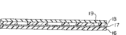
In above-mentioned common decoration wallboard manufacture method, the pattern on the wallboard etc. directly applies by serigraphy.To introduce a kind of manufacture method of utilizing the transfer printing mode to apply now.Figure 25 is the sectional view of an example of a kind of common transfer printing-coated sheet of expression.This transfer printing-coated sheet comprises back side transfer paper 16, the hot pressing type adhesive phase 17 above the transfer paper 16 overleaf, the patterned layer 18 on hot pressing type adhesive phase 17 surfaces, and end face transfer paper 19.Patterned layer 18 forms by above-mentioned serigraphy.
In common transfer printing painting method, coating stands hot pressing by above-mentioned transfer printing type coated sheet and carries out on a metal base plate.
By the way, the surface of above-mentioned decoration wallboard scribbles transparent protective coating, protects pattern or coloured surface to avoid destroying thus, gives a kind of space or depth perception simultaneously.The dope layer of this performance generally directly carries out by serigraphy, rather than applies by the transfer printing mode.
In above-mentioned common metal lagging, ink logo 4 forms by serigraphy, and this serigraphy needs the step of many complexity, thereby needs a large amount of time to make.If a kind of multicolor patterns is particularly arranged, just need silk screen plate 7 with the same quantity of color variety.Because will use different coating successively, so need a large amount of steps.Owing to make new silk screen plate 7 along with the change of pattern is essential, so cost of production improves at every turn.
In addition, common metal finishing wallboard does not have overcoat, so they are prone to crackle, and does not have space or depth perception.In view of this, generally behind pattern transferring, form one deck overcoat, make its drying then.Yet this needs a large amount of time and cost.
Japanese patent laid-open discloses a kind of metal lagging 1991 No. 205145, it is to form like this: form relief pattern by printing on the metal sheet that has an even surface, form the thin intermediate layer that still keeps concavo-convex thereon, on the intermediate layer, form transparent or painted filming again.Relief pattern wherein is monochromatic, and still exists the problem identical as serigraphy.
The present invention can be used to address the above problem.According to one object of the present invention, a kind of metal lagging and manufacture method thereof are provided, they can reduce production time and cost, and a kind of texture of the patterned surfaces that can make and space or depth perception, even and very near-earth is seen and do not seen that also pattern has any disorder, and can on the whole surface of metal lagging, provide colored pattern.
To achieve these goals, the metal lagging that provides comprises:
One metal base plate; And
One transparent overcoat, it is formed on the metal base plate, and includes the colored pattern that is formed by subliming type printing ink.
According to another object of the present invention, a kind of method of making metal lagging is provided, the step that it comprises is:
Transparent overcoat is provided on metal base plate;
The transfer printing type coated paper that will have the colored pattern that subliming type printing ink makes is superimposed on transparent overcoat; And
Make the subliming type ink sublimation, so that colored pattern is transferred on the transparent overcoat.
According to purpose in addition of the present invention, a kind of method of making metal lagging is provided, the step that it comprises is:
With a large amount of fiber implanted metal base plates to form fibrage;
The transfer printing type coated paper that will have the colored pattern that subliming type printing ink makes is superimposed on fibrage; And
Make the subliming type ink sublimation, so that colored pattern is transferred on the fibrage.
Advantage of the present invention is, can reduce time and the cost of producing this metal lagging, and a kind of texture of the patterned surfaces that can make and space or depth perception, and can provide colored pattern on the whole surface of metal lagging.
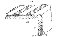
Fig. 1 is the sectional perspective view according to a metal lagging of first embodiment of the invention;
Fig. 2 is the process chart that a kind of method of decorative panel shown in Figure 1 is made in explanation;
Fig. 3 A is the schematic diagram of explanation step of manufacturing shown in Figure 2 to 3F;
Fig. 4 is the sectional perspective view according to the metal lagging of second embodiment of the invention;
Fig. 5 A is the sectional perspective view according to a metal lagging of third embodiment of the invention;
Fig. 5 B is the sectional view of the amplification of a presentation graphs 5A part;
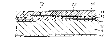
Fig. 6 is the sectional perspective view according to a metal lagging of sixth embodiment of the invention;
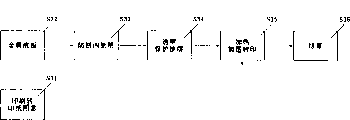
Fig. 7 is the process chart that a kind of method of decorative panel shown in Figure 6 is made in explanation;
Fig. 8 A is the schematic diagram of explanation step of manufacturing shown in Figure 7 to 8F;
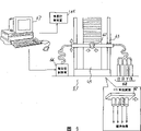
Fig. 9 is the sketch of system architecture that expression is used for a kind of ink-jet printer of method shown in Figure 7;
Figure 10 is the phantom drawing of expression according to the major part of an example of the decoration wallboard of metal lagging formation shown in Figure 6;
Figure 11 is the sectional view according to a metal lagging of seventh embodiment of the invention;
Figure 12 is the sectional view according to a metal lagging of eighth embodiment of the invention;
Figure 13 is the sectional view according to a metal lagging of ninth embodiment of the invention;
Figure 14 is the sectional view according to a metal lagging of tenth embodiment of the invention;
Figure 15 is the sectional view according to a metal lagging of eleventh embodiment of the invention;
Figure 16 is the sectional view according to a metal lagging of twelveth embodiment of the invention;
Figure 17 is the sectional view according to a metal lagging of thriteenth embodiment of the invention;
Figure 18 is the sectional view according to a metal lagging of fourteenth embodiment of the invention;
Figure 19 is the sectional view according to a metal lagging of fifteenth embodiment of the invention;
Figure 20 is the sectional view according to a metal lagging of sixteenth embodiment of the invention;
Figure 21 is the sectional view of an example of the common decoration wallboard of expression;
Figure 22 is that explanation is made common a kind of method of decoration wallboard shown in Figure 21 and prepared to be used for a kind of process chart of method of the silk screen plate of decoration wallboard shown in Figure 21;
Figure 23 A is the schematic diagram of explanation step of manufacturing shown in Figure 22 to 23G;
Figure 24 A is the schematic diagram that the step of the method for preparing silk screen plate shown in Figure 22 is described to 24D;
Figure 25 is the sectional view of the common example of transfer printing type coated sheet of expression.
By consulting accompanying drawing embodiments of the invention are described now.
First embodiment
Fig. 1 is the sectional perspective view according to a metal lagging of first embodiment of the invention.In the drawings, the painted undercoating of being made up of for example whitewash 21 is formed at the surface of metal base plate 1.Painted undercoating 21 also can be used as antirust coat.By transparent coating, for example the transparent overcoat 5 (following abbreviation " overcoat ") of acrylic acid series coating, polyester type coatings or urine gastral cavity type coating composition is coated on the painted undercoating 21.Topping 5 includes the subliming type toner 22 as subliming type printing ink, forms colored pattern 23 by it.Can make dyestuff and plastic grain in conjunction with obtaining subliming type toner 22 by (for example).
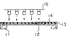
Then will introduce the method for making metal lagging shown in Figure 1.Fig. 2 is the process chart that is used for illustrating the method for making metal lagging shown in Figure 1; And Fig. 3 A is the schematic diagram that is used for illustrating step of manufacturing shown in Figure 2 to 3F.
At first, as shown in Figure 3A, the colored pattern of being made by subliming type toner 22 23 utilizes a kind of subliming type toner printing machine 24 to be printed on transfer paper on (separating low) 25 (step S31), prepares a transfer printing type coated sheet 26 thus.In this method, subliming type toner printing machine 24 can be connected on a PC or the similar computer, so that can arbitrarily design colored pattern 23.
Then, shown in Fig. 3 B, antirust undercoating is coated on the surface of metal base plate 1, thereby forms painted undercoating 21 (step S33).After painted undercoating 21 dryings, layer of transparent coating is coated in above it, form overcoat 5 (step S34) after this clear coat drying.
After this, shown in Fig. 3 D, that transfer printing type coated sheet 26 is superimposed on overcoat 5.Then, shown in Fig. 3 E, utilize heat/pressure roller 44 level and vertical and 45 under suitable temperature and pressure, to heat and roll extrusion transfer printing type coated sheet 26 (step S35), thereby make the subliming type toner 22 on the transfer printing type coated sheet 26 be entered overcoat 5 by distillation, thus with colored pattern 23 transfer printings on overcoat 5.At last, shown in Fig. 3 F, transfer paper 25 is peeled off, to form metal lagging (step S36).
In this metal lagging, can utilize subliming type toner printing machine 24 on metal base plate 1, to repeat to print the colored pattern 23 of fine definition.In addition, with common, compare by the metal lagging of silk screen printing, the manufacture method of this metal lagging is simpler than prior art, and compared with prior art only needs less time and lower cost of production.In addition, because subliming type toner 22 enters transparent overcoat 5, thereby can obtain a kind of metal lagging that satisfactory color manifests performance and good fast light anti-wear performance that has.Also have, as long as to superimposed 26 heating of transfer printing type coated sheet and pressurization on overcoat, colored pattern 23 not only also can easily form on the horizontal plane but also on vertical plane.
In addition, because painted undercoating 21 is arranged, therefore can prevent that metal base plate 1 from getting rusty, and can make it have good surface appearance.
Second embodiment
Fig. 4 is the sectional perspective view according to a metal lagging of second embodiment of the invention.In this figure, overcoat 5 is by transparent coating, and for example acrylic acid series coating, polyester type coatings or urine gastral cavity type coating are formed, and add aluminium powder 27 as flashlight powder.Except that recited above, the metal lagging of present embodiment is basically the same as those in the first embodiment.The method that forms colored pattern 23 also is basically the same as those in the first embodiment.
Because aluminium powder 27 is dispersed in 5 li of overcoats, so the metal lagging of present embodiment makes the back except the function with first embodiment, also has the metallic luster of polishing shape.In addition, the aluminium powder 27 that is dispersed in 5 li of overcoats can provide a kind of metallic luster to colored pattern, and it might make the inconsistency of color not too remarkable, and this inconsistency can produce in the colored pattern of topping 5 to a certain extent.
In second embodiment, glossiness powder is not limited to aluminium powder 27.Also can use other metal dust.Except metal dust, also can use the powder of mica powder and so on, they can give wallboard with pearly luster.
In addition, in first and second embodiment, also can on overcoat 5, provide other clear dope, prevent that thus the subliming type toner 22 that has entered overcoat 5 from fading, and makes colored pattern obtain more reliable protection simultaneously.
The 3rd embodiment
Fig. 5 A is the sectional perspective view according to a metal lagging of third embodiment of the invention; And Fig. 5 B is the sectional view of the amplification of the part among Fig. 5 A.In these figure, scribble painted undercoating 21 on the surface of metal base plate 1.Clear dope layer 28 as transparent overcoat is formed on the painted undercoating 21.Shown in Fig. 5 B, clear dope layer 28 is made up of the clear dope 28a that is mixing many spherical transparent grain 28b.Clear dope 28a and transparent grain 28b (for example) can be made up of a kind of acrylic acid series material.The big I of this transparent grain 28b is slightly larger than subliming type toner 22.Subliming type toner 22 enters clear dope 28 in the same manner as in the first embodiment and forms colored pattern 23.
This metal lagging that replaces overcoats 5 with clear dope layer 28 except function with first embodiment, on the surface of making, also present trickle irregular, thereby a kind of delustring texture appears.In addition, because this layout can make the inconsistency of colored pattern not too remarkable.Also have, because subliming type toner 22 enters spherical transparent grain 28b, so it can make colored pattern 23 have third dimension.
The profile of transparent grain 28b is not limited to sphere.
The 4th embodiment
Then introduce the fourth embodiment of the present invention.In the 4th embodiment, many fine fibres (natural or synthetic fibers) (not shown) is added into 5 li of the overcoats of first embodiment.Method that it prepares colored pattern 23 or the like is basically the same as those in the first embodiment.
This metal lagging can obtain the effect identical with first embodiment.In addition, the irregular surface that forms owing to the adding fiber can make the inconsistency of subliming type toner 22 not too remarkable.
Though overcoat 5 or transparent dope layer 28 or the like are that painted undercoating 21 by the centre is formed on the metal base plate 1 in first to the 4th embodiment, also can save painted undercoating 21, and transparent dope layer 28 grades directly are formed on the metal base plate 1.When metal base plate 1 (for example) is by corrosion resistant plate, brass sheet, when aluminium sheet or red metal plate are made, can produce a kind of specular layer on the surface of metal base plate 1, hair layer (hair-linefinish), polishing layer or similar surface layer sensation, and on overcoat 5, form colored pattern 23 in these cases, make decorative panel have unique outward appearance thus.Yet, when with common steel plate during, should coat undercoating 21 from purpose such as antirust as metal base plate.
In addition, though in the first, the second and the 4th embodiment, transparent overcoat 5 is transparent, also can use translucent overcoat, as long as still can see colored pattern.
The 5th embodiment
Then introduce the fifth embodiment of the present invention.In the metal lagging of the 5th embodiment, use the transfer printing type coated sheet of using in first embodiment, make the colored pattern transfer printing on a fibrage (not shown) by distillation, this fibrage is by forming on the fiber implanted metal base plate.
When making this metal lagging, earlier a kind of cementing agent is coated on the metal base plate surface that scribbles antirust coat, thereby forms an adhesive layer.Then, fine fibre is implanted adhesive layer, to form fibrage with electrostatic method.The transfer printing type coated sheet that will have the colored pattern that is formed by the subliming type toner then is superimposed on fibrage, makes subliming type toner distillation, thus with the colored pattern transfer printing on fibrage.
Open 2-59068 number of a visible Japan Patent of example of static implantation fibre technology.The fibrous material that present embodiment uses can be nylon or acrylic fibers.
This method also can form the colored pattern of fine definition.In addition.Compare with common serigraphy, this method only needs simple production technology, short production time and lower cost of production.Also have, for the surface that makes pattern, it can provide the outward appearance of the soft cloth with the degree of depth and fiber gloss.
In addition, there is the fibrage of colored pattern also can form one deck overcoat by clear dope being offered transfer printing, thereby not only can protects Manufactured surface, also can provide the degree of depth and gloss to patterned surface.In addition, also can prevent from colored pattern to be faded because of ultraviolet ray etc.
The 6th embodiment
Fig. 6 is the sectional view according to a metal lagging of sixth embodiment of the invention.In this figure, antirust coat 2 is formed at metal base plate 1 both sides by methods such as coatings.The opaque resin bed 52 of one film shape is formed on the antirust coat 2 of wallboard front surface by intermediate adhesive layer 51.
The transparent resin layer 54 of film shape is coated on the opaque resin bed 52 as adhesive layer 53 intermediates of transparent overcoat by layer of transparent, and transparent resin bed 54 (for example) is made up of a kind of polyester or acrylic films.In addition, the printing ink with a kind of subliming type adds transparent resin bed 54 to form colored pattern 55.The part that sees through the transparent resin layer 54 that does not have colored pattern 55 can be seen the color of opaque resin layer 52.Adhesive layer 51 can be made up of the sort of cementing agent that is similar to adhesive layer 53.
Then will introduce the method for making metal lagging shown in Figure 6.Fig. 7 is the process chart that a kind of method of metal lagging shown in Figure 6 is made in explanation; And Fig. 8 A is the schematic diagram of each step of the technological process of presentation graphs 7 to 8F.
At first, antirusting paint is coated in (step S21) on the metal base plate 1, to form antirust coat 2.Then, opaque resin bed 52 and transparent resin bed 54 are bonded in successively on the leading flank of antirust coat (step S22 and S23), to form the decoration base plate 56 shown in Fig. 8 A.In addition, shown in Fig. 8 B, the colored pattern 55 that is formed by subliming type printing ink is imprinted on the transfer paper (separation paper) 58 by a kind of ink-jet printer 57, thereby is ready to transfer printing type coated sheet 59.
After this, shown in Fig. 8 C, that transfer printing type coated sheet 59 is superimposed on the transparent resin layer 54 of decorating base plate 56.Then, as shown in Figure 8, by making the pattern on the transfer printing type coated sheet 58 be transferred (step S25) in heating under the suitable temperature and pressure and pressurization, thus, subliming type printing ink on the transfer printing type coated sheet 58 is entered transparent resin bed 54 by distillation, thereby colored pattern is transferred on the transparent resin bed 54.Then, transfer paper is peeled off, made metal lagging.
Then, shown in Fig. 8 E, the bight of the metal lagging made is prescinded (step S26).Then, shown in Fig. 8 F (step S27), carry out flanging, form and decorate wallboard (step S28).
Fig. 9 is the sketch of expression ink-jet printer 57 system architectures.In this figure, but be used for spraying of device 63 controls of the ink nozzle 62 of subliming type printing ink, can on whole transfer paper 58, freely move thus by two dimensional motion.Ink nozzle 62 is connected on the container 64, and R (redness) is arranged in this container, B (blue look), Y (yellow), BL pigment such as (black).In addition, ink nozzle 62 also is connected with an ink-jet control device 65.The device 63 of two dimensional motion is connected with a driving control device 66.Drive unit 65 is connected with the computer of being made up of PC or similar devices 67 with 66.
57 li of the ink-jet printers with said system structure, the data about colored pattern 55 of being collected by (for example) input scanner (not shown) or input PC (not shown) are imported into 67 li in computer, and to signal that should data by computer 67 apparatus for controlling of supply 65 and 66, quantity of the pigment of controlling position, the color of ink nozzle 62 thus and providing or the like, thus colored pattern 55 formed.
In the metal lagging made from said method,, can on metal base plate 1, print out the colored pattern 55 (7-15 point/millimeter) of fine definition by ink-jet printer 57.In addition, this metal lagging only can utilize to be needed than simple fabrication process, the method for shorter manufacturing time and low manufacturing cost and making.In addition, because subliming type printing ink enters transparent resin bed 54, therefore can obtain a kind of metal lagging that satisfactory color manifests performance and good fast light anti-wear performance that has.Above-mentioned metal lagging can be produced in a large number, with as a kind of steel plate that applies in advance.
In addition, since the shaping operation such as bending of wallboard be at colored pattern 55 transfer printing on metal base plate 56, also promptly after making, metal lagging carries out, so colored pattern 55 can easily appear on the surfaces such as the flanging surface of wallboard or curved surfaces, can give of the ornamental effect of (for example) elevator door thus to strengthen.In addition, have transparent resin bed 54 that excellent color manifests performance as the aspect of accepting sublimation inks owing to use, therefore when fractureing, even with the wallboard behind the printed pattern when crooked, colored pattern 55 can not be damaged yet.In addition, owing in the design of colored pattern 55, have the freedom of height, therefore can on the basis of multi-varieties and small-batch, produce and decorate wallboard.
In addition, owing in the 6th embodiment computer 67 is being inserted in the system of ink-jet printers 57, so colored pattern 55 can easily become (for example) photo-patterns of a kind of stable fine definition.
Though in the 6th embodiment, colored pattern 55 is to be imprinted on the transfer paper 58 by the ink-jet printer 57 by computer 67 controls, also can utilize the chromatic printing machine of other pattern, for example utilizes a kind of electrostatic toning control system to form colored pattern.
In addition, though opaque resin bed 52 and transparent resin bed 54 are film shape in the 6th implementation column, also can it be existed with the coating form by (for example) polyester or acrylic acid series coating are provided.
The subliming type printing ink that forms colored pattern 55 is usually by a kind of colored materials, and adhesive and ink formulation medium are formed.Colored materials can be a kind of pigment, natural dye or synthetic dyestuffs.Adhesive can comprise; Water-soluble binder, as cellulose-type binder, acryloid cement, or starch adhesives; And the resin that dissolves in organic solvent, as acrylic resin, methacrylic resin, polystyrene, Merlon, polysulfones, polyether sulfone (polyethersulfone), or ethyl cellulose.
The ink formulation medium comprises: wine is clear, as methyl alcohol, and isopropyl alcohol, or isobutanol; Molten fine agent is as molten fine agent of methyl or the molten fine agent of ethyl; Aromatic, as toluene, dimethylbenzene, or chlorobenzene; The ester class is as ethyl acetate or butyl acetate; Ketone is as acetone or methyl ethyl ketone; Ethers is as oxolane or dioxane; And organic solvent, as N, N-dimethyl formyl gastral cavity, or the upright ketone (N-methyl pyrolidone) of N-methylpyrrole.
The 7th embodiment
Figure 11 is the sectional view according to a kind of metal lagging of seventh embodiment of the invention.The structure of the metal lagging of present embodiment replaces the transparent resin layers 54 except the painted transparent resin layer 71 with the film shape, other identical with the 6th embodiment.The identical method manufacturing of its metal finishing board fabrication method available and the 6th embodiment.
Use color that painted transparent resin layer 71 can show this resin bed and secondary colour, thereby give degree of depth of picture patterned surface around the color of the opaque resin undercoating 52 of colored pattern 55.
The 8th embodiment
Figure 12 is the sectional view according to a metal lagging of eighth embodiment of the invention.The structure of the metal lagging of present embodiment and manufacture method be except stamping the bottom pattern 72 on the surface of the opaque resin bed 52 of the 6th embodiment by red ink paste used for seals or similar fashion, and remaining is identical with the 6th embodiment all.
In this metal lagging, the colored pattern 55 on the transparent resin layer 54 is stacked on the bottom pattern 72, thereby a kind of relief comprehensive pattern that has occurs.
The 9th embodiment
Figure 13 is the sectional view according to a metal lagging of ninth embodiment of the invention.The metal lagging of present embodiment uses opaque resin bed 73, and is wherein mixing the metal dust such as aluminium powder.
In this metal lagging, by that part of metal dust of seeing that does not have colored pattern 55 to form on the transparent resin layer 54, thereby a kind of metal pattern with degree of depth appears.When being mixed in them wherein with replacement, the surface that metal dust is sticked to opaque resin layer 73 also can obtain identical effect.
The tenth embodiment
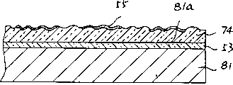
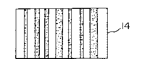
Figure 14 is the sectional view according to a metal lagging of tenth embodiment of the invention.The metal lagging of present embodiment has many grooves and projection on the surface of transparent resin layer 74.These grooves and projection are used as a kind of embossment, for example a kind of trees-cereal top layer embossment that matches with colored pattern 55.
In this metal lagging, a kind of texture is arranged by colored pattern 55 is combined the surface that can make pattern with groove and projection.
The 11 embodiment
Figure 15 is the sectional view according to a metal lagging of eleventh embodiment of the invention.The metal lagging of present embodiment is to form transparent dope layer 75 by the surface at the metal lagging that is similar to the 6th embodiment to obtain.This structure can be protected colored pattern 55, and can make colored pattern 55 ageing-resistant, and fast light, wear-resisting, aspects such as chemically-resistant variation are improved.
The 12 embodiment
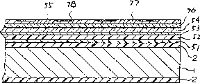
Figure 16 is the sectional view according to a metal lagging of twelveth embodiment of the invention.The metal lagging of present embodiment obtains by the following method: form a transparent resin layer 77 by an adhesive layer 76 intermediate mediums on the transparent resin layer 54 of the 6th embodiment, and form colored pattern 55 and 78 respectively on transparent resin layer 54 and 77.
In this metal lagging, double-deck colored pattern 55 and 78 superimposed on background color, thus make patterned surface have the degree of depth and the third dimension of increase.In addition, also can show comprehensive pattern.Though two-layer transparent resin bed 54 and 77 are arranged in present embodiment, three layers or more multi-layered transparent resin layer can also be arranged, and colored pattern is arranged respectively on it.
The 13 embodiment
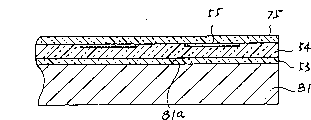
Figure 17 is the sectional view according to a metal lagging of thriteenth embodiment of the invention.Shown metal lagging is bright and clean by making the metal base plate 81 that is formed by (for example) corrosion resistant plate or aluminium sheet reach minute surface, and hair is bright and clean or the like (for example grinding), obtains thereby form the surperficial 81a with metallic luster.Being similar to the such transparent resin layer of the 6th embodiment 54 is formed on the surperficial 81a that has metallic luster by one deck adhesive layer 53 intermediate mediums.Described as the 6th embodiment, colored pattern 55 is formed on 54 li of transparent resin beds.
In this metal lagging, see through the gloss that colored pattern 55 can be seen the surperficial 81a that has metallic luster, therefore, metallic luster and colored pattern 55 can obtain a kind of comprehensive pattern with unique look by being combined.For example, combine with the colored pattern 55 of yellow, can give pattern a kind of unusual gold by the corrosion resistant plate that will have mirror finish.
The 14 embodiment
As shown in figure 18, a kind of have the groove shown in the tenth embodiment and the transparent resin layer 74 of projection also can be provided, with the transparent resin layer 54 that replaces the 13 embodiment, can obtain complicated patterns style more by combining with the pattern style that forms by groove and projection thus by the pattern style that metallic luster forms.
The 15 embodiment
As shown in figure 19, also one deck can be coated on the transparent resin bed 54 of the 13 embodiment as the described transparent dope layer 75 of the 11 embodiment, thereby can obtain ageing-resistant at colored pattern 55, fast light, wear-resisting, the improvement of aspects such as chemically-resistant variation, and still keep the outward appearance that produces by metallic luster.
The 16 embodiment
As shown in figure 20, also can be as described in the 12 embodiment, on the transparent resin layer 54 of the 13 embodiment, provide layer of transparent resin bed 77 by cementing agent 76 intermediate mediums, so that form colored pattern 78 thereon, can obtain the effect identical thus, but still keep the visual sense that metallic luster produces with the 12 embodiment.
In addition, though do not draw, a kind of painted transparent resin layer 71 that is similar to the 7th embodiment can be used for replacing the described transparent resin layer 54 of the 13 embodiment naturally.
Claims (17)
1. a metal lagging comprises:
-metal base plate; And
-transparent overcoat, it is formed on the metal base plate;
It is characterized in that described transparent overcoat includes the colored pattern that subliming type printing ink forms.
2. metal lagging as claimed in claim 1 is characterized in that, a painted undercoating is formed between described metal base plate and the described transparent overcoat.
3. metal lagging as claimed in claim 1 is characterized in that, a kind of glossiness powder is dispersed in the described transparent overcoat.
4. metal lagging as claimed in claim 1 is characterized in that, a large amount of transparent particulate dispersion are in described transparent overcoat.
5. metal lagging as claimed in claim 1 is characterized in that, a large amount of implanted described transparent overcoats of fiber.
6. metal lagging as claimed in claim 1 is characterized in that, described transparent overcoat comprises the layer of transparent resin bed.
7. metal lagging as claimed in claim 6 is characterized in that there are a large amount of projections and groove in the surface of described transparent resin layer.
8. metal lagging as claimed in claim 6 is characterized in that, the clear dope layer is arranged on the described transparent resin layer.
9. metal lagging as claimed in claim 6 is characterized in that, the formation that overlaps each other of all transparent resin layers.
10. metal lagging as claimed in claim 6 is characterized in that, has the metallic luster that mirror finish forms on the surface of described metal base plate.
11. metal lagging as claimed in claim 6 is characterized in that, between described transparent resin layer and described metal base plate opaque resin bed is arranged.
12. metal lagging as claimed in claim 11 is characterized in that, in the described opaque resin layer bottom pattern is arranged.
13. metal lagging as claimed in claim 11 is characterized in that, a kind of metal dust is dispersed in the described opaque resin layer or sticks on the described opaque resin layer.
14. a method of making metal lagging, the step that comprises is:
Transparent overcoat is provided on metal base plate;
The transfer printing type coated sheet that will have the colored pattern of being made by subliming type printing ink is superimposed on described transparent overcoat; And
Make described subliming type ink sublimation, so that described colored pattern transfer printing is on described transparent overcoat.
15. method as claimed in claim 14, it is characterized in that, also further being included in provides described transparent overcoat the preceding step that the opaque resin bed of one deck is provided on described metal base plate, and wherein has a transparent resin bed to be used as described transparent overcoat.
16. method as claimed in claim 14 is characterized in that, also further being included in provides the surface that makes described metal base plate before the described transparent overcoat to have the step of the metallic luster that mirror finish forms.
17. a method of making metal lagging, the step that it comprises is:
With a large amount of fiber implanted metal base plates to form fibrage;
The transfer printing type coated paper that will have the colored pattern that subliming type printing ink makes is superimposed on described fibrage; And
Make described subliming type ink sublimation, so that the colored pattern transfer printing is on fibrage.
Applications Claiming Priority (6)
| Application Number | Priority Date | Filing Date | Title |
|---|---|---|---|
| JP11164293A JP2908666B2 (en) | 1993-05-13 | 1993-05-13 | Manufacturing method of metal decorative panel |
| JP111642/1993 | 1993-05-13 | ||
| JP111642/93 | 1993-05-13 | ||
| JP251789/1993 | 1993-10-07 | ||
| JP25178993A JP2957864B2 (en) | 1993-10-07 | 1993-10-07 | Metal decorative plate and manufacturing method thereof |
| JP251789/93 | 1993-10-07 |
Publications (2)
| Publication Number | Publication Date |
|---|---|
| CN1097230A CN1097230A (en) | 1995-01-11 |
| CN1064103C true CN1064103C (en) | 2001-04-04 |
Family
ID=26450986
Family Applications (1)
| Application Number | Title | Priority Date | Filing Date |
|---|---|---|---|
| CN 94105196 Expired - Fee Related CN1064103C (en) | 1993-05-13 | 1994-05-13 | Decorative metal plate and process for manufacturing the same |
Country Status (3)
| Country | Link |
|---|---|
| KR (1) | KR0133254B1 (en) |
| CN (1) | CN1064103C (en) |
| TW (1) | TW253872B (en) |
Families Citing this family (4)
| Publication number | Priority date | Publication date | Assignee | Title |
|---|---|---|---|---|
| KR20020045170A (en) * | 2000-12-08 | 2002-06-19 | 김팔성 | method for spread multi film of metal plate |
| JP4056963B2 (en) * | 2002-11-14 | 2008-03-05 | 松下冷機株式会社 | Method of manufacturing metal decorative plate with sublimation transfer pattern and metal decorative plate, method of manufacturing heat insulating panel and heat insulating panel, method of manufacturing refrigerator door and refrigerator door |
| TWI408010B (en) * | 2010-09-13 | 2013-09-11 | Nat Univ Kaohsiung | Paint jade manufacturing method |
| CN106280702A (en) * | 2016-08-15 | 2017-01-04 | 汕头市金株新材料有限公司 | A kind of noble metal preparation of silk screen printing |
-
1994
- 1994-05-03 TW TW83103969A patent/TW253872B/zh active
- 1994-05-12 KR KR1019940010414A patent/KR0133254B1/en not_active IP Right Cessation
- 1994-05-13 CN CN 94105196 patent/CN1064103C/en not_active Expired - Fee Related
Also Published As
| Publication number | Publication date |
|---|---|
| CN1097230A (en) | 1995-01-11 |
| TW253872B (en) | 1995-08-11 |
| KR0133254B1 (en) | 1998-04-18 |
Similar Documents
| Publication | Publication Date | Title |
|---|---|---|
| CN1235250C (en) | Key-top plate and method for making same | |
| CN1305686C (en) | Digitally printed products and process | |
| CN1708391A (en) | Methods and systems for producing a desired apparent coloring in an object produced through rapid prototyping | |
| CN101678394B (en) | Process for color variability in printing to simulate color variation of natural product | |
| CN1097252C (en) | Sheet for marking, marked sheet, and method for manufacturing said sheet | |
| CN106029595A (en) | Methods for printing on glass | |
| CN1070776C (en) | Decorative sheet | |
| CN1655944A (en) | Method and apparatus for creating an image on an article, and printed article | |
| KR20170024972A (en) | An Interior film having various color surface embo patterns and the manufacturing method thereof | |
| CN1088656C (en) | Image transfer method, and substrate for transfer and ink ribbon used therefor | |
| CN1883957A (en) | Non-impact transfer printing method and device therefor | |
| CN1064103C (en) | Decorative metal plate and process for manufacturing the same | |
| CN105102234A (en) | Method for producing decorative prints having identical quality independently of the printing method used, and a device for performing said method | |
| CN1715081A (en) | Steel plate printed with pattern on surface and its transfer method and color life plate | |
| CN1636721A (en) | System and method for printing image pattern on object | |
| CN105946232A (en) | Colouring method for 3D printing technology | |
| CN1057047C (en) | Method for transferring designs and patterns | |
| CN1350935A (en) | Process for preparing optical reflection material of colour pattern | |
| CN1759151A (en) | Printing system | |
| KR20090046134A (en) | Method of decoration plate for building interior wall panel | |
| KR101056279B1 (en) | Printed mother-of-pearl sheet and it's making method | |
| JP3128105U (en) | Accessories | |
| WO2000040661A1 (en) | Printing composition, process and printing device using the same | |
| US20110217652A1 (en) | Process for applying a powder coating | |
| JPH07102733A (en) | Metallic decoration plate and production thereof |
Legal Events
| Date | Code | Title | Description |
|---|---|---|---|
| C10 | Entry into substantive examination | ||
| SE01 | Entry into force of request for substantive examination | ||
| C06 | Publication | ||
| PB01 | Publication | ||
| C14 | Grant of patent or utility model | ||
| GR01 | Patent grant | ||
| C19 | Lapse of patent right due to non-payment of the annual fee | ||
| CF01 | Termination of patent right due to non-payment of annual fee |