CN106228527B - System and method for calibrating display system using manual and semi-automatic techniques - Google Patents
System and method for calibrating display system using manual and semi-automatic techniques Download PDFInfo
- Publication number
- CN106228527B CN106228527B CN201610816106.8A CN201610816106A CN106228527B CN 106228527 B CN106228527 B CN 106228527B CN 201610816106 A CN201610816106 A CN 201610816106A CN 106228527 B CN106228527 B CN 106228527B
- Authority
- CN
- China
- Prior art keywords
- screen
- projector
- corresponding points
- mapping
- points
- Prior art date
- Legal status (The legal status is an assumption and is not a legal conclusion. Google has not performed a legal analysis and makes no representation as to the accuracy of the status listed.)
- Active
Links
- 238000000034 method Methods 0.000 title claims abstract description 85
- 238000013507 mapping Methods 0.000 claims description 99
- 239000011159 matrix material Substances 0.000 claims description 11
- 239000003086 colorant Substances 0.000 claims description 7
- 238000007670 refining Methods 0.000 claims 2
- 230000008569 process Effects 0.000 abstract description 21
- 230000007246 mechanism Effects 0.000 description 12
- 238000006073 displacement reaction Methods 0.000 description 8
- 238000012937 correction Methods 0.000 description 6
- 230000003287 optical effect Effects 0.000 description 6
- 239000000872 buffer Substances 0.000 description 5
- 238000012986 modification Methods 0.000 description 5
- 230000004048 modification Effects 0.000 description 5
- 238000012545 processing Methods 0.000 description 5
- 238000012935 Averaging Methods 0.000 description 3
- 238000010586 diagram Methods 0.000 description 3
- 238000002347 injection Methods 0.000 description 3
- 239000007924 injection Substances 0.000 description 3
- 238000002156 mixing Methods 0.000 description 3
- 230000010287 polarization Effects 0.000 description 3
- 238000013459 approach Methods 0.000 description 2
- 230000008859 change Effects 0.000 description 2
- 238000004891 communication Methods 0.000 description 2
- 241000226585 Antennaria plantaginifolia Species 0.000 description 1
- 238000007792 addition Methods 0.000 description 1
- 230000009286 beneficial effect Effects 0.000 description 1
- 230000008901 benefit Effects 0.000 description 1
- 230000007812 deficiency Effects 0.000 description 1
- 230000001419 dependent effect Effects 0.000 description 1
- HAKMAMKAFTZXOZ-UHFFFAOYSA-N dioctoxyphosphorylbenzene Chemical compound CCCCCCCCOP(=O)(OCCCCCCCC)C1=CC=CC=C1 HAKMAMKAFTZXOZ-UHFFFAOYSA-N 0.000 description 1
- 230000000694 effects Effects 0.000 description 1
- 238000005516 engineering process Methods 0.000 description 1
- 239000011521 glass Substances 0.000 description 1
- 238000003702 image correction Methods 0.000 description 1
- 230000006872 improvement Effects 0.000 description 1
- 238000004519 manufacturing process Methods 0.000 description 1
- 239000000203 mixture Substances 0.000 description 1
- 238000004088 simulation Methods 0.000 description 1
- 230000001131 transforming effect Effects 0.000 description 1
- 238000013519 translation Methods 0.000 description 1
- 230000000007 visual effect Effects 0.000 description 1
Images


Classifications
-
- G06T5/80—
-
- G—PHYSICS
- G03—PHOTOGRAPHY; CINEMATOGRAPHY; ANALOGOUS TECHNIQUES USING WAVES OTHER THAN OPTICAL WAVES; ELECTROGRAPHY; HOLOGRAPHY
- G03B—APPARATUS OR ARRANGEMENTS FOR TAKING PHOTOGRAPHS OR FOR PROJECTING OR VIEWING THEM; APPARATUS OR ARRANGEMENTS EMPLOYING ANALOGOUS TECHNIQUES USING WAVES OTHER THAN OPTICAL WAVES; ACCESSORIES THEREFOR
- G03B21/00—Projectors or projection-type viewers; Accessories therefor
- G03B21/14—Details
- G03B21/147—Optical correction of image distortions, e.g. keystone
-
- H—ELECTRICITY
- H04—ELECTRIC COMMUNICATION TECHNIQUE
- H04N—PICTORIAL COMMUNICATION, e.g. TELEVISION
- H04N9/00—Details of colour television systems
- H04N9/12—Picture reproducers
- H04N9/31—Projection devices for colour picture display, e.g. using electronic spatial light modulators [ESLM]
- H04N9/3141—Constructional details thereof
- H04N9/3147—Multi-projection systems
-
- H—ELECTRICITY
- H04—ELECTRIC COMMUNICATION TECHNIQUE
- H04N—PICTORIAL COMMUNICATION, e.g. TELEVISION
- H04N9/00—Details of colour television systems
- H04N9/12—Picture reproducers
- H04N9/31—Projection devices for colour picture display, e.g. using electronic spatial light modulators [ESLM]
- H04N9/3179—Video signal processing therefor
- H04N9/3182—Colour adjustment, e.g. white balance, shading or gamut
-
- H—ELECTRICITY
- H04—ELECTRIC COMMUNICATION TECHNIQUE
- H04N—PICTORIAL COMMUNICATION, e.g. TELEVISION
- H04N9/00—Details of colour television systems
- H04N9/12—Picture reproducers
- H04N9/31—Projection devices for colour picture display, e.g. using electronic spatial light modulators [ESLM]
- H04N9/3179—Video signal processing therefor
- H04N9/3185—Geometric adjustment, e.g. keystone or convergence
-
- H—ELECTRICITY
- H04—ELECTRIC COMMUNICATION TECHNIQUE
- H04N—PICTORIAL COMMUNICATION, e.g. TELEVISION
- H04N9/00—Details of colour television systems
- H04N9/12—Picture reproducers
- H04N9/31—Projection devices for colour picture display, e.g. using electronic spatial light modulators [ESLM]
- H04N9/3197—Projection devices for colour picture display, e.g. using electronic spatial light modulators [ESLM] using light modulating optical valves
Abstract
The present invention provides a system and method that reduces the tediousness and required accuracy of manual calibration procedures. The user selects the projectors or corresponding points between the components of the projectors to form a common coordinate system. The common coordinate system can be quickly mapped to the entire display using the model of the display system and the projector. This process avoids the need to measure screen points and allows the user to move a greatly reduced number of points. In addition, the present invention allows the introduction of machine vision type algorithms in manual calibration techniques to improve performance. This overcomes the complexity of existing systems by introducing a model of the display into the manual calibration process, requiring only a small number of points to be selected on each projector, and avoiding the need to select screen points that need to be measured accurately. Instead, the system finds the corresponding points between the projectors, allowing the projectors to map to a common coordinate system and quickly warp this common coordinate system to the screen.
Description
Divisional application
The present application is a divisional application entitled "system and method for calibrating a display system using manual and semi-automatic techniques" filed on application No. 201180064209.9, filed on 2011, 11/15.
Technical Field
The present invention relates to displays and focuses on, but is not limited to, multi-projection display systems. More particularly, the present invention relates to calibration of such displays and display systems.
Background
People like to watch images around them. Size, brightness, resolution, contrast, 3D, and many other features are attracting the attention of viewers. The goal of creating a display system is to create the best possible experience for the viewer. Creating an optimal experience often means optimizing the display quality. Quality factors include, but are not limited to, geometric accuracy, color accuracy, contrast, resolution, and freedom to disperse artifacts (free from transforming artifacts) and other performance characteristics that generally contribute to making the image properties pleasing. These factors may also include allowing the displayed digital image to accurately render the original digital image or images found in nature. To obtain the best possible user experience and/or display quality, some inaccuracies in the images produced by the display screen need to be corrected by rectifying the image information and debugging the operating point of the display system.
Examples OF such displays are listed in commonly assigned U.S. published patent application 2008/0246781A1 entitled "System AND METHOD for providing IMPROVED display quality BY display ADJUSTMENT AND IMAGE processing Using light FEEDBACK" (claiming priority OF U.S. divisional application sequence 60/895, 070) AND U.S. patent application sequence 12/049, 267, entitled "MAPPING function injection System AND METHOD (SYSTEM AND METHOD OF MAPPINJETION artifact)" which disclosure is incorporated BY reference as background information for each OF the different display types that may be useful.
For example, flat panel type displays are often subject to color and brightness speckles within their panels, as well as color and brightness differences on the panels. They also have drawbacks due to different input-output curves. For example, two or more separate displays can display low brightness gray shades very similarly, but the high brightness gray shades may vary greatly across different panels. Troublesome geometric problems may also be caused by panel shading, multiple panel misalignment, the need for non-conventional display shapes within a panel, the alignment of multiple panels in shape (e.g., cylindrical), and the like.
Projection-based displays suffer from geometric distortions (sometimes on single color channels) often due to imperfect optics within the projector. They also suffer from problems due to brightness variations within or on the projector, color gloss, color mismatch on the projector, jetness variations, different input-output curves, etc.,
for the display of 3D images, different images are often presented to the right and left eyes, respectively. Methods of accomplishing this task include using time to alternate the images delivered to each eye, using light properties such as polarization or wavelength to select which eye will receive which particular image, using optics to attempt to deliver a different image to each eye based on the spatial location of the eye, and the like. For 3D imagery, as it uses standard imagery, there are as a result geometric artifacts, color and intensity artifacts, and potentially different artifacts of the imagery intended for each eye.
The modifications to the SYSTEM may occur at various stages in the IMAGE display processing chain in one example, the modifications may occur when creating digital signals, as described in detail in the "MAPPING function INJECTION SYSTEM AND METHOD (System AND METHOD FOR INJECTION OF MAPPING FUNCTIONS)" incorporated herein, a particular example OF a related projector or intermediate deformation box such as OMTE parameters is illustrated AND detailed, as described in detail in the incorporated U.S. patent application entitled "System AND METHOD FOR providing IMPROVED display quality BY display ADJUSTMENT AND IMAGE processing using optical FEEDBACK (SYSTEM AND METHOD FOR IMAGE correction AND IMAGE processing) (L Y applied manufacturing METHOD DISP L AY L ITY BY DISP L AY ADJUSS METHOD AND IMAGE PROFILING OPCA L EDBACK)".
The types of modifications considered herein typically include distortion of the image onto the screen, if projectors are utilized, one such modification requires blending the image across the projectors so that the total brightness of an area overlaid by multiple projectors is similar to the brightness of the rest of the display.
Manual geometric calibration is the process of obtaining a geometric correction (deformation) of an image that a user specifies to be displayed on a display. For manual geometric calibration, the prior art in the field typically involves the application of a large amount of precision, which tends to be tedious to achieve.
The most common method of manually calibrating projectors in conventional implementations is perfect calibration on a flat screen, for an array of l × N projectors, for example, these projectors are set up so that the projected image has no relative vertical offset and known horizontal offset.
If the projector is not precisely aligned, or its mapping does not have a perfect scale factor, the second method of manual calibration involves moving a large number of points to indicate that it should beThe correction is applied to each projector. Typically these points are selected by a pointing device such as a mouse. Two examples of criteria include applications such as WatchoutTM(available from Dataton, Inc. of forest and snow, Sweden) and eWarpDesignerTM(available from Flexible Picture Systems, Inc. of Rinshima, Ontario, Canada). In each of these typical applications, the user has a grid of points starting at evenly spaced intervals on the projector. The points are moved to indicate where the image sent to the projector should actually be displayed on the projector; that is, the points represent the deformation of the input image projected onto the screen. Typically, a grid of about 7 by 9 points (typically done within eWarpDesigner) must be moved, and typically must be moved exactly, 63 points per projector. This work is tedious. Typically, to do this accurately, it is necessary to pre-measure the screen and place small dots on the screen so that the user can move the points on the projector to the correct locations on the screen so that the image will be mapped correctly onto the screen. Accuracy is often necessary, especially in the overlap region, because small misalignments in the overlap region can become noticeable when the final image is displayed due to shadowing effects. In general, the lack of precision can lead to artifacts, such as an image moving on the display system, shrinking and expanding as it moves, or oscillating slightly up and down.
Another example of a manual calibration is an application from 3D grace (norway). In the software launched with its compactUTM deformation box, the user can obtain one model with the position of each projector in 3D space, how it projects the imagery, and the screen. The starting point is very helpful because it provides an initial estimate of the system distortion, but again, to refine the model to achieve good alignment between projectors, multiple points on each projector must be moved separately to correct the distortion to achieve a match between projectors.
These types of manual methods for modifying and updating the distortion do not typically take advantage of the shape of the screen, or the fact that the display unit can be modeled, such as a projector with radial distortion as a 4 × 3 projection matrix, and they do not use any algorithms that form constraints between projectors.
Disclosure of Invention
The present invention overcomes the deficiencies of the prior art by reducing the tediousness and accuracy requirements of the manual calibration process. The user selects the correspondence between multiple projectors and/or the correspondence between multiple components of a single projector, allowing them to form a common coordinate system across the entire projector system. With the model of the display system and the projector, the user can quickly map the common coordinate system to the entire display screen. In this process, the illustrative embodiments avoid the need to measure points accurately on the screen, and generally only require fewer points to be moved during the calibration process.
Or in this way, the object of the present invention is to introduce an algorithm of the machine vision type into the manual calibration technique, to be implemented faster, more easily and with less complexity. The system and method thus overcomes the cumbersome nature of the prior art by introducing a model of the display system into the manual calibration process. This allows the user to select relatively few points on each projector and avoids selecting precisely measured points on the screen. Instead, the system and method find corresponding points between multiple projectors, which allows the projectors to be mapped onto one common (world) coordinate system, and then allows the user to quickly warp the common coordinate system onto the screen.
Drawings
The invention will be described hereinafter with reference to the accompanying drawings, in which:
FIG. 1 is a block diagram of an exemplary manual calibration display system in accordance with a general embodiment of the present invention;
FIG. 2 is a flow chart illustrating the steps of obtaining a manual geometric calibration;
FIG. 3 is a flow chart showing the steps of obtaining a mapping from one projector to another;
FIG. 4 is a block diagram of an exemplary manual alignment display system using a cylindrical screen;
FIG. 5 is an image showing an example of a cross-section of a feature displayed on a screen to achieve sub-pixel calibration accuracy;
FIG. 6 is a flowchart showing the steps of obtaining a manual calibration when the model of the projector is known in advance;
FIG. 7 is a block diagram of an exemplary display system with manual calibration for measuring distortion between colors within a projector according to embodiments of the present invention; and
fig. 8 is a flow chart showing the steps of a manual calibration procedure in which the mapping from the projector to the common coordinate system and the mapping from the coordinate system to the screen are updated simultaneously.
Detailed Description
Illustrative examples
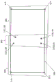
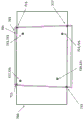
Fig. 1 shows outlines 101 and 103 of two images projected from two projectors falling within a flat screen area 100. The outline need not necessarily be rectangular, and trapezoidal shapes are depicted as examples. In further examples, various geometries are obviously conceivable. In the overlap region 105, the projections of both projectors are overlapped on the screen 100. In the area 105, several positions are selected on each projector. The user may accomplish this task by clicking within an overlapping position on each projector using, for example, a mouse. Each "X" represents a location selected by a user or other mechanism on projector 101, and each "O" represents a location selected on projector 103. Within the overlap region 105, four X-O corresponding point pairs are shown: x (127) corresponds to O (129), X (131) corresponds to O (133), X (119) corresponds to O (121), and X (123) corresponds to O (125). These pairs of corresponding points can be used to form a mapping from one projector to another. Four pairs are sufficient to form a homography matrix between the projectors. For flat screens, the homography matrix is a good choice for mapping between projectors, since it represents the mapping from one projector to another quite accurately. Other mapping arrangements and implementations are possible, including mappings based on bilinear mappings, radial basis functions, quadratic curves, splines, triangular meshes, and the like. The mapping should generally include some amount of inherent smoothness or be limited in some way to construct a smooth representation in order to make the generally desirable smooth mapping from the input image of the projector to the projected image representative. Some mappings (e.g., bilinear mappings) do not necessarily have to have four corresponding points, while other types of mappings may require more corresponding points to properly map two geometries to each other. The selected point need not necessarily be located at any specially measured location. Instead, the selected point can be located at almost any position within the overlap region, which we refer to as the corresponding point can be located at any position, i.e. these positions need not necessarily be located at a particular point on the screen. For the corresponding points, the only constraint is typically the constraint of the mapping itself. For example, for the case of a homography, the four corresponding points may not be collinear.
Once the mapping is established between the projectors, a common (world) coordinate system is defined to which the user can map the image to and through the two projectors onto the screen.
Once the mapping is established, the user (or other mechanism) can select points 111, 113, 115, and 117 at the corners of the screen and form a homography matrix from the common coordinate system to the screen. In a desirable embodiment, the image on the screen may be updated in real time so that as the user selects a point, he/she can see the image movement.
If the system contains more than two projectors in the entire group, the process described above with respect to fig. 1 can be performed for each pair of projectors in the entire group. Without limitation, such as the traditional least squares method may be used to resolve any non-correspondence between the pairwise mappings. That is, one can find a set of mappings that minimizes the sum of squared errors for each corresponding pair of points. If more than two projectors share the same overlap area, it is helpful, but not generally necessary, to utilize the same corresponding points on more than two projectors. It is noted that typically edge blending is used in a multi-projector system to balance brightness, and the parameters of such blending can be calculated in a well-known way using the obtained mapping.
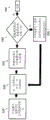
Fig. 2 shows a procedure including the general steps for obtaining a manual geometric calibration of a system with multiple projectors. In a first step 210, a mapping from one projector to another projector is found using the corresponding points. This allows a single coordinate system to be formed on the projector. In a second step 220, the user or other mechanism finds a mapping from the separate coordinate system to the screen. In a final step 230, the user or other mechanism optionally refines the system.
Fig. 3 shows the process of completing the mapping between projectors. First the user or other entity selects the corresponding point in step 310. The user or other entity then forms a map between the projector pairs (step 320) and displays an image in the overlap area of at least one projector pair (step 330). By observing the overlapping images in the projector pair, the user or other mechanism can decide whether to accept the mapping or to improve the mapping further (decision step 340). If desired, the user or institution may refine the existing correspondence points or select additional correspondence points for greater accuracy (step 360). The improvement in this case requires fine-tuning the exact position on the screen where a certain input image falls, as described below. The complexity of the mapping in 320 is then increased-e.g., by adding more parameters to the mapping. Optionally, the mapping may be updated for better adaptability. As a further alternative, the disparity between mapped corresponding points may be defined as a displacement field, and the displacement field may be corrected using a spline curve or other representation of the displacement field. The process of adding and/or modifying corresponding points may be repeated by the user or other entity until completed (step 350).
It is noted that once a map is formed, an additional step may be performed in various embodiments. A position is selected on one projector and moved to match a position on a second projector. That is, once the map is formed, a user or other entity may explicitly select a location within one projector, but may only implicitly select a location within a second projector.
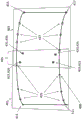
In fig. 4, the process of fig. 1 is performed by a typical lenticular screen 400. The outlines of the images projected from the two projectors 401 and 403 are shown. There is an overlap region 405 within which the corresponding point X-O pair, X (419) O (421) and X (423) O (425) and X (427) O (429) and X (431) O (433) are selected in substantially the same manner as the planar screen example described above. The two projectors 401, 403 can be mapped to a common coordinate system using homography matrices and a single image can be displayed across the system in a manner as generally described herein. Since the screen is curved in this example, four points may not be sufficient to create an acceptable alignment in the overlap region, in which case more corresponding points may be selected as described in figure 3 to perfect the homography matrix into a more complex representation of the displacement and hence a more accurate representation of the mapping. Once a common coordinate system is formed, a single image can be displayed over the entire system. The corner points 411, 413, 415 and 417 can generally be selected in a simple and straightforward manner, since these points define the required fill area on the screen. In addition, a user or other mechanism may select points along the edges, typically along the top and bottom edges of the screen, until a curve can be fitted and controlled to delineate the fill area. These points are points 435 and 437 in the projected image. These points need not be chosen in a uniformly spaced manner on the curve and therefore need not be exactly known in their location. A sufficient number of points are selected to accurately represent the curves at the top and bottom of the image.
The projector can be considered as an object having optical characteristics. For example, these characteristics may include: displacement of the focal length, position, direction, optical axis from the center of the projected image. A minimization process is selected to optimize these parameters while minimizing the least squares error of the distances of the corner points to the points where they project back into the projector, the squared distances of the points on the edge curve selected back into the projector according to the existing set of parameters to the edges of the cylinder in the projector, and the squared distances between the rays of the two projectors that are supposed to intersect at the corresponding points. Once the convergence is minimized, the image can be projected onto the screen so that the image is uniformly distributed along the width of the cylinder in the horizontal direction and uniformly distributed along the height of the cylinder in the vertical direction.
FIG. 5 is an example of a fiducial that is a useful tool for finding corresponding locations on a screen to sub-pixel accuracy. The illustrated reference 501 is a binary gaussian function (i.e., orthogonal x-y axes in the image plane). This function is displayed on each projector and can be moved relative to each other and then calibration is carried out. In this manner, the center of each gaussian blur may form a correspondence. Curve 503 shows the intensity cross section of the gaussian function. A fuzzy or anti-aliasing reference like these is beneficial because human eyes are good at averaging over an area. By placing two brightness-attenuating fiducials within an overlap region on a pair of projectors, a user can move the fiducials by a half pixel or less, while the eyes can observe and find the difference in the consistency of the overlap, and move the fiducials to compensate for the inconsistency. It is expressly contemplated that various trained machine vision tools may be used in place of the eye to perform the determination of overlap consistency in alternative embodiments.
Fig. 6 shows an embodiment of a procedure involving special cases, where a strong prediction of the model can be obtained in advance. This may be the case because the display system has been simulated and the parameters of the projector are known. Another situation may be true where the auto-calibration system has estimated parameters and the system displays deviations from these parameters. For example, in some cases, the position, orientation, and focal length of the projector, radial distortion, and lens translation are known to be within certain tolerances. In another case, the user can use all the information to find the appropriate mapping between the projector and the screen. However, due to the ubiquitous tolerances, the results of calibration in a typical case may not be perfect.
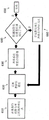
As previously described, a user or other mechanism may select a corresponding point between a pair of overlapping projectors (step 610). This information can be used to update the model (step 620), which implicitly forms a mapping from one projector to another. In an illustrative embodiment, the process includes a non-linear minimization process that obtains the sum of the squares of errors of the distances from the projector through their corresponding points of light, while allowing the projector model parameters to vary within known tolerances. Once each model is updated, the user or other entity may display images on the system (step 630) and then decide whether the images are visually well-aligned on the system (decision step 640). If the images are not well aligned, the user or other mechanism may select additional corresponding points between the projectors to update each model (step 660 and then step 620 again). The associated steps 620, 630, 640 and 660 may be repeated until completed (step 650). As previously described, the user or other entity may choose to decide to correct any inconsistencies by defining a mapping between projectors as a displacement field and adding the displacement field to the model of the projector being projected onto the screen.
It is noted that in order to obtain the minimization described in fig. 6, it is necessary to use a reference selected on the screen with known three-dimensional (3D) coordinates, such as a corner of the screen, or a visible intersection between various portions of the screen. These constraints in 3D can increase speed and provide additional robustness to the overall procedure.
Fig. 7 shows an embodiment of a single projector projected on a flat screen. For example, the projector has two colors that fall on the screen 700 and fill the areas 701 and 703, respectively. This is an example of lateral color distortion, in which case the colors of the projectors do not overlap in the manner they would have been. In this case, several dots can be selected in each color to form a mapping between color channels. In this case, 4 pairs of corresponding point pairs of "X" to "0" have been selected: 719 corresponds to 721, 723 corresponds to 725, 731 corresponds to 733, and 727 corresponds to 729. Once the mapping between colors into a common coordinate system is formed, the common coordinate system can be mapped onto the screen. In this case, 711, 713, 715, and 717 denoted by "X" are selected. Thus, the process is virtually the same as in fig. 1, except that the corresponding points are selected within the same projector but different color channels.
FIG. 8 illustrates one embodiment of updating the mapping from the projector to the common coordinate system using additional information. The first few steps are exactly the same as done in fig. 4. In step 810, a mapping to a common coordinate system is formed as described above. In step 820, additional information about boundaries, known fiducial points, edges, and/or corners is collected (in FIG. 4, such information is collected for the boundaries and corner points of the screen). In step 830, the merged information is used to form a mapping from the common coordinate system to the screen as was done in FIG. 4. In step 840, both the mapping to the common coordinate system and the mapping from the common coordinate system to the screen are updated simultaneously. In one illustrative embodiment, this is accomplished by simulating a projector as an optical object as described above. In this case, the mapping from the projector to the common coordinate system may be improved by estimating the projection matrix of the projector. Also, the changed mapping to the common coordinate system may affect the mapping from the common coordinate system to the screen. For example, as a result, the minimization process of finding the optical characteristics of the projector described by fig. 4 can be used to simultaneously change the mapping to the common coordinate system and the mapping from the common coordinate system to the screen.
Optional additional embodiments and examples
The following are detailed examples of implementations that employ the teachings of the present inventive concept.
With the aid of background information and further description, and with reference to fig. 1, it is assumed that each projector operates with three primary colors, red, green, and blue. That is, the projector forms an image by projecting red, green, and blue pixels superimposed on each other. In this case, each projector can be considered to be three (3) projectors. The mapping between color channels within a single projector may be based on pincushion or barrel distortion. By selecting several points in each color, the user or other mechanism can find the parameters of the known deformation function and then move each color into a common coordinate system as described in fig. 7. The procedure described above can then continue in the manner previously described except that in this example the system is considered to actually utilize six projectors instead of two, and the simulation of the mapping between the projectors is different from the mapping within the projectors.
Another example is where the projector attempts to display multiple buffers. It may be a 3D image, attempting to provide a different image for each eye. It is contemplated that each buffer corresponds to a different person's visual habits and requirements. If the projector uses polarization, differential color, or time division multiplexing techniques for each eye, or similar techniques, it is contemplated to store a different color in each buffer. At the time when the color shift or polarization or buffer is selected without the assistance of glasses, the user can view the imagery generated by both buffers in this example, as suggested by FIG. 7. The system is then in fact treated as a two-color system, operating exactly as a three-color system according to the above description.
In one illustrative example, four (4) projectors are installed in the 2 × 2 mode to fill a flat screen, each projector driven by a different computer that implements TCP/IP communications over Ethernet lines or other acceptable communications paths and/or protocols.
Using these overlapping points, an exemplary software program and/or algorithm can form a common coordinate system on all four projectors using a homography matrix. As more points are selected, the model between projectors is over-constrained. That is, the map has a certain number of parameters, and when there are too many points, it is generally not possible to utilize the map accurately and achieve a perfect match between overlapping points, for which a second stage in the map may be required. The mapping functions may be corrected using thin-plate spline curves or other representations of the displacement fields so that, in the common coordinate system created between each pair of projectors, the locations in the overlap region that have been indicated as being to be overlapped actually overlap. Once a common coordinate system is established, it is possible to display templates, such as a grid of points covering the entire projector system. The user or other entity can indicate the errors by recording points on each projector that do not substantially perfectly overlap, thereby observing the errors in the mapping to the single coordinate system, where the errors are not present if the points are actually perfectly overlapping. Optionally, the user or other entity can then select more points to help improve the mapping between projectors, or move existing points on the grid on each projector separately to refine the mapping.
Once a satisfactory result is achieved, the user or other entity can view the entire projector system as a large coordinate system and move a point around the joint area of the projectors, in which case moving a point affects all projectors controlled by the point.
Another example of an embodiment that employs the illustrative concepts provided herein is to provide several projectors on a cylindrical screen of approximately known radius, height and angle, where the screen edges are visible and the seams are visible at known locations on the screen, as shown in fig. 4. In this case, a plurality of points are selected within the overlap area as described previously. Points at the corners of the screen and points at a reference where there is visibility on the screen, such as at the edges of a seam on the screen, may also be selected. By selecting these points, a 3D correspondence (position of the screen) to a 2D position within the projector is actually established. The mapping from the input of the projector to the screen can be simulated using a pinhole model or similar model of the projector. In one approach, a projection matrix for each projector to the screen is formed by selecting six (6) points on each projector. Then select the overlap point that completes the model, or add corrections on top of the model to map each projector correctly on top of each other. Alternatively, it is envisaged that additional information may be available in order to increase the complexity of the model, for example to introduce a correction for radial distortion within the projection lens.
According to an exemplary embodiment, when less than six points are available, the problem to be solved is equivalent to the beam-balancing program/algorithm utilized in machine vision systems. In these programs/algorithms, there is a minimization process that makes it possible to determine projector parameters, which here may include position, orientation, focal length, center of projection, etc. The objective is to minimize the reprojected square error of points that a selected projector has in common back into the projector and the square error of points on the selected screen. It is noted that if the screen size is only roughly known, these parameters can be included in the minimization process and still give good results. A step of appropriately mapping a curve on the screen edge may be added to this type of minimization process, as in the description of fig. 4.
Furthermore, when these types of minimization are complete, the results can be used to construct a mapping from one projector to another. That is, the information about the screen and the parameters of the projection can be used to simultaneously construct a mapping of the projectors to each other and to the screen from a common coordinate system. In this way, the geometry of the screen can be used to help form a mapping from the projector to the common coordinate system. This concept is discussed in step 840 of fig. 8.
A program that is useful in several screen types is one that has vanishing points. Sometimes, the user or other mechanism can easily select a point that is directly below a point on the top of the screen. The increase in corner points indicates a rectangle projected by the projector. With the vanishing point technique, the rectangle is sufficient to predict the angle between the projector and the screen. This type of technique helps to initiate the minimization process of non-linearity. This type of technique is also applicable in cases where some parameters of the projector (e.g. internal parameters) are known. These internal parameters may include the focus on the projector position. Thus, this technique may be used in conjunction with additional information provided by known parameters.
In another embodiment, see fig. 4, the screen in this case is the same in the vertical direction, considering that the screen therein is not a cylindrical screen but may be a pressed screen. Even in this case, good results can be obtained. If enough points are selected on the top and bottom boundaries or on the projector, the boundaries can be folded back into the projector, and it is these points that need to do. The projection parameters of the projector can then be determined by minimizing the shape of the screen that is constrained (the top and bottom edges must be parallel curves). There are several methods of handling embossed screens using camera/projector feedback systems that suggest several algorithms available here, including those published by AditiMajundar et al, and a product published by Scalable display technologies of Cambridge, MA for use in Scalable desktop.
There are typically many procedures for each screen type by which it can be calculated how the image should be mapped onto the screen. For cylindrical screens, the image is generally distorted around the cylinder so that the pixels are given equal angles along the cylinder and the pixels are evenly distributed in a direction perpendicular to the cylinder axis. Information from the overlap region or from the projector position can be used to predict the effective resolution of the system, and the best resolution for viewing the image on the screen. One simple way to accomplish this estimation would be to calculate the number of pixels lost in the overlap region. An alternative method for displaying images can employ acquired background (rendered scene) based on frustum (frusta). In this illustrative example, a viewpoint may be set at the center of the cylinder and an appropriate frustum is selected for each projector for projector-dependent angular filling. In an alternative embodiment, the user or other mechanism may move the viewpoint to a different location than the center of the cylinder.
In one example, one screen may be defined as a portion of one spherical screen, illustratively extending 60 degrees from right to left and 30 degrees up/down. The mapping for this type of screen can be solved in much the same way as the cylindrical screen described above, by constraining multiple projectors by selecting points and then selecting points on the screen edges to form a curve. These curves can then be used to create a minimization process to iterate the optical characteristics of the projectors to fit the curves to the maximum extent while complying with the constraints between projectors.
In a further embodiment, a corner portion may be included in the screen, or a hard edge may be included. This may be the case when projecting at the corners of a room, or when projecting on an entire screen system consisting of several flat screens converging at a junction. This situation is substantially similar to that of other screens, where the user can also click on the edge or corner of the screen using a mouse to identify the location where the mapping is desired to be sharp in direction. Similar to the case of a flat screen, a homography matrix may be established with respect to each wall, and corner points may be selected to form an overall mapping.
In another embodiment, the screen is not known about the screen except that it can change smoothly, in which case it is still possible to create a single coordinate system by mapping between all projectors.A small number of points can be moved within a unified coordinate system to represent where an image should be, since there is no known a priori information.
It is an object of the invention to determine the correspondence between projectors on the sub-pixel level. Thus, when moving points back and forth across the screen, the points typically move on a single pixel level, so that the correspondence between projectors is not established at the sub-pixel level. However, the eye is sensitive to region averaging, and this averaging can be used to achieve sub-pixel matching. For example, rather than selecting a point on the projector, a function-e.g., a Gaussian function-is moved around the screen with intensity attenuation over a large number of pixels. The eye can interpolate the intensity peaks of the function and the smooth edges of the attenuation on the screen. Thus, the user can move the number of sub-pixels of the peak and match the peak and edge from one projector to another, and thus obtain a correspondence of sub-pixel accuracy. A similar approach can be implemented by using an antialiased crosshair over a large number of pixels, or with other images having intensity gradients. Automated techniques for determining sub-pixel level correspondences may also be employed.
It should be apparent that the systems and methods described herein provide a highly efficient technique for mapping multiple projectors that provide imagery to a single screen with a wide range of geometries. The system and method are equally applicable to a variety of specific applications. Such applications include, but are not limited to, (a) setting projector values, (b) setting deformation box values, (c) setting easy blendTMSDK value, (d) set OMTE parameters, set Nvidia (graphics card and graphics engine) color profile parameters, (e) set resolution required for DOPP screen, (f) calculate coordinated shading on screen, (g) typically used to deploy multiple projectors, single projector, flat panel display (e.g. gamma curve and spatial intensity correction), whiteboard/whiteboard, touch screen and/or flight simulator.
The foregoing has described in detail embodiments of the present invention. Various modifications and additions can be made without departing from the spirit and scope of the invention. The various embodiments described above may be combined with other described embodiments to provide a variety of features. Furthermore, while the foregoing describes several separate embodiments of the apparatus and method of the present invention, the description herein is merely illustrative of the application of the principles of the invention. For example, additional correction steps beyond those described herein may be employed. These steps may be performed based on, inter alia, the type of display device and the display screen surface employed. Furthermore, where a person may perform a certain step of a certain program, it is simply envisioned that a suitable automated device or mechanism may be used interchangeably with the user, such as using a machine vision system that obtains screen images and performs conventional, programmed vision system processing on the images. The term "manual" should therefore be understood in a broad sense to include steps that are performed entirely or at least partially with the aid of automated operations. Likewise, it is expressly contemplated that the techniques provided herein can be applied to calibrating a single projector that is part of a projection system having two or more projectors, or calibrating a single unit of a projection system. In the case where calibration of a single projector is performed, the term "projectors" is to be understood in a broad sense, including individual "components" of a single projector image. Further, it is expressly contemplated that any of the procedures and functions described herein can be implemented in hardware, software, including a computer-readable medium containing program instructions, or a combination of hardware and software. Accordingly, this description is to be construed as illustrative only and is not intended to limit the scope of the present invention.
Claims (20)
1. A method of calibrating one or more projectors, comprising:
displaying a first projection image on a screen through a first projector;
displaying a second projected image on the screen by a second projector, thereby defining an overlapping area where the first projected image and the second projected image overlap on the screen;
selecting a first plurality of corresponding points corresponding to the first projector and a second plurality of corresponding points corresponding to the second projector such that each of the first plurality of corresponding points overlaps and corresponds to a respective one of the second plurality of corresponding points, the first plurality of corresponding points being different from the first projected image and the second projected image;
determining a first mapping from the first projector to the second projector using the first plurality of corresponding points and the second plurality of corresponding points, thereby defining a common coordinate system between the first projector and the second projector;
selecting a third plurality of corresponding points corresponding to points on the screen, at least one of the third plurality of corresponding points corresponding to: boundary points, curves, corners or edges of the screen, and located outside the overlap region;
determining a second mapping from the common coordinate system to the screen using the selected third plurality of corresponding points; and
an image is displayed on the screen by the first projector and the second projector according to the first mapping and the second mapping.
2. The method of claim 1, wherein the first and second pluralities of corresponding points are located at arbitrary locations on a screen.
3. The method of claim 1, wherein at least a portion of the screen comprises at least one of: a flat screen, a cylindrical screen, or a pressed screen.
4. The method of claim 1, wherein the displaying an image step further comprises: the displayed image is updated in real-time based on an update to at least one of the first mapping and the second mapping.
5. The method of claim 2, wherein the second mapping is determined based on a geometry of the screen.
6. The method of claim 1, wherein determining the first mapping and determining the second mapping are performed simultaneously.
7. The method of claim 1, wherein the step of selecting the first and second pluralities of corresponding points comprises displaying an image on the screen, the image being defined by a brightness attenuation at predetermined corresponding points, whereby the images of the two or more projectors are movable to achieve sub-pixel matching between the images of the first and second projectors.
8. The method of claim 1, wherein the step of selecting the first plurality of corresponding points and the second plurality of corresponding points comprises displaying the corresponding points in different colors within the overlap region to allow determination of the calibration, wherein a new color is formed in combination with at least two different colors.
9. The method of claim 1, wherein determining the first mapping comprises determining an estimate of the first mapping based on the first and second pluralities of corresponding points and refining the estimate of the first mapping.
10. The method of claim 1, wherein the first plurality of corresponding points and the second plurality of corresponding points are within an overlap region.
11. A method of calibrating one or more projectors, comprising:
displaying a first projection image on a screen through a first projector;
displaying a second projected image on the screen by a second projector, thereby defining an overlapping area where the first projected image and the second projected image overlap on the screen;
selecting a first plurality of corresponding points corresponding to a first projector and displaying the selected first plurality of corresponding points on a screen with a first projected image in an overlap region on the screen, the first plurality of corresponding points being non-collinear;
selecting a second plurality of corresponding points corresponding to the second projector and displaying the selected second plurality of corresponding points on the screen with the second projected image in the overlapping region on the screen such that each of the first plurality of corresponding points displayed on the screen overlaps and corresponds to a respective one of the second plurality of corresponding points displayed on the screen, the second plurality of corresponding points being non-collinear;
determining a first mapping from the first projector to the second projector using the first plurality of corresponding points and the second plurality of corresponding points, thereby defining a common coordinate system between the first projector and the second projector, the first mapping comprising a homography matrix between the first plurality of corresponding points and the second plurality of corresponding points;
selecting a third plurality of corresponding points corresponding to points on the screen, at least one of the third plurality of corresponding points corresponding to: boundary points, curves, corners or edges of the screen, and located outside the overlap region;
determining a second mapping from the common coordinate system to the screen using the selected third plurality of corresponding points; and
an image is displayed on the screen by the first projector and the second projector according to the first mapping and the second mapping.
12. The method of claim 11, wherein the first and second pluralities of corresponding points are located at arbitrary locations on a screen.
13. The method of claim 11, wherein at least a portion of the screen comprises at least one of: a flat screen, a cylindrical screen, or a pressed screen.
14. The method of claim 11, wherein the displaying an image step further comprises: the displayed image is updated in real-time based on an update to at least one of the first mapping and the second mapping.
15. The method of claim 13, wherein the second mapping is determined based on a geometry of the screen.
16. The method of claim 11, wherein determining the first mapping and determining the second mapping are performed simultaneously.
17. The method of claim 11, wherein determining the first mapping comprises determining an estimate of the first mapping based on the first and second pluralities of corresponding points and refining the estimate of the first mapping.
18. The method of claim 11, wherein the first plurality of corresponding points and the second plurality of corresponding points are within an overlap region.
19. A system for calibrating one or more projectors, comprising:
a first projector for displaying a first projected image on a screen;
a second projector for displaying a second projected image on the screen, thereby defining an overlapping area where the first projected image and the second projected image overlap on the screen; and
a processor configured to:
selecting a first plurality of corresponding points corresponding to the first projector and a second plurality of corresponding points corresponding to the second projector such that each of the first plurality of corresponding points overlaps and corresponds to a respective one of the second plurality of corresponding points, the first plurality of corresponding points being different from the first projected image and the second projected image;
determining a first mapping from the first projector to the second projector using the first plurality of corresponding points and the second plurality of corresponding points, thereby defining a common coordinate system between the first projector and the second projector;
selecting a third plurality of corresponding points corresponding to points on the screen, at least one of the third plurality of corresponding points corresponding to: boundary points, curves, corners or edges of the screen, and located outside the overlap region;
determining a second mapping from the common coordinate system to the screen using the selected third plurality of corresponding points; and
an image is displayed on the screen by the first projector and the second projector according to the first mapping and the second mapping.
20. A system for calibrating one or more projectors, comprising:
a first projector for displaying a first projected image on a screen;
a second projector for displaying a second projected image on the screen, thereby defining an overlapping area where the first projected image and the second projected image overlap on the screen; and
a processor configured to:
selecting a first plurality of corresponding points corresponding to a first projector and displaying the selected first plurality of corresponding points on a screen with a first projected image in an overlap region on the screen, the first plurality of corresponding points being non-collinear;
selecting a second plurality of corresponding points corresponding to the second projector and displaying the selected second plurality of corresponding points on the screen with the second projected image in the overlapping region on the screen such that each of the first plurality of corresponding points displayed on the screen overlaps and corresponds to a respective one of the second plurality of corresponding points displayed on the screen, the second plurality of corresponding points being non-collinear;
determining a first mapping from the first projector to the second projector using the first plurality of corresponding points and the second plurality of corresponding points, thereby defining a common coordinate system between the first projector and the second projector, the first mapping comprising a homography matrix between the first plurality of corresponding points and the second plurality of corresponding points;
selecting a third plurality of corresponding points corresponding to points on the screen, at least one of the third plurality of corresponding points corresponding to: boundary points, curves, corners or edges of the screen, and located outside the overlap region;
determining a second mapping from the common coordinate system to the screen using the selected third plurality of corresponding points; and
an image is displayed on the screen by the first projector and the second projector according to the first mapping and the second mapping.
Applications Claiming Priority (3)
| Application Number | Priority Date | Filing Date | Title |
|---|---|---|---|
| US41352010P | 2010-11-15 | 2010-11-15 | |
| US61/413,520 | 2010-11-15 | ||
| CN201180064209.9A CN103329540B (en) | 2010-11-15 | 2011-11-15 | Utilize manually and semi-automated techniques calibrates the system and method for display system |
Related Parent Applications (1)
| Application Number | Title | Priority Date | Filing Date |
|---|---|---|---|
| CN201180064209.9A Division CN103329540B (en) | 2010-11-15 | 2011-11-15 | Utilize manually and semi-automated techniques calibrates the system and method for display system |
Publications (2)
| Publication Number | Publication Date |
|---|---|
| CN106228527A CN106228527A (en) | 2016-12-14 |
| CN106228527B true CN106228527B (en) | 2020-08-04 |
Family
ID=45099192
Family Applications (2)
| Application Number | Title | Priority Date | Filing Date |
|---|---|---|---|
| CN201180064209.9A Active CN103329540B (en) | 2010-11-15 | 2011-11-15 | Utilize manually and semi-automated techniques calibrates the system and method for display system |
| CN201610816106.8A Active CN106228527B (en) | 2010-11-15 | 2011-11-15 | System and method for calibrating display system using manual and semi-automatic techniques |
Family Applications Before (1)
| Application Number | Title | Priority Date | Filing Date |
|---|---|---|---|
| CN201180064209.9A Active CN103329540B (en) | 2010-11-15 | 2011-11-15 | Utilize manually and semi-automated techniques calibrates the system and method for display system |
Country Status (6)
| Country | Link |
|---|---|
| US (3) | US9369683B2 (en) |
| EP (1) | EP2641400B1 (en) |
| JP (2) | JP6198605B2 (en) |
| KR (2) | KR20180117717A (en) |
| CN (2) | CN103329540B (en) |
| WO (1) | WO2012068112A1 (en) |
Families Citing this family (31)
| Publication number | Priority date | Publication date | Assignee | Title |
|---|---|---|---|---|
| CN103329540B (en) * | 2010-11-15 | 2016-08-24 | 斯加勒宝展示技术有限公司 | Utilize manually and semi-automated techniques calibrates the system and method for display system |
| EP2839454A4 (en) * | 2012-04-19 | 2016-03-16 | Scalable Display Technologies Inc | System and method of calibrating a display system free of variation in system input resolution |
| US8922486B2 (en) * | 2012-07-24 | 2014-12-30 | Christie Digital Systems Usa, Inc. | Method, system and apparatus for determining locations in a projected image |
| JP6164820B2 (en) * | 2012-10-11 | 2017-07-19 | キヤノン株式会社 | Projector, control method therefor, and image projection system |
| EP2972585A4 (en) * | 2013-03-15 | 2016-10-19 | Scalable Display Technologies Inc | System and method for calibrating a display system using a short throw camera |
| JP6299071B2 (en) * | 2013-03-27 | 2018-03-28 | セイコーエプソン株式会社 | Projector, image correction method and program |
| JP2015026992A (en) * | 2013-07-26 | 2015-02-05 | 株式会社リコー | Projection system, image processing device, projection method, and program |
| KR101515368B1 (en) * | 2013-08-26 | 2015-04-27 | 씨제이씨지브이 주식회사 | Method for clustering projectors, management apparatus and system using the same |
| US10080004B2 (en) | 2014-11-06 | 2018-09-18 | Disney Enterprises, Inc. | Method and system for projector calibration |
| US10691006B2 (en) * | 2014-12-09 | 2020-06-23 | Imax Theatres International Limited | Methods and systems of vibrating a screen |
| US9816287B2 (en) * | 2014-12-22 | 2017-11-14 | Cyberoptics Corporation | Updating calibration of a three-dimensional measurement system |
| JP6594170B2 (en) * | 2015-11-12 | 2019-10-23 | キヤノン株式会社 | Image processing apparatus, image processing method, image projection system, and program |
| AU2015275255A1 (en) | 2015-12-22 | 2017-07-06 | Canon Kabushiki Kaisha | Multi-projector alignment refinement |
| US10083652B2 (en) | 2016-05-04 | 2018-09-25 | International Business Machines Corporation | Method, apparatus and computer product to compensate for misaligned or overlapped electronic wallpapers |
| US9992464B1 (en) | 2016-11-11 | 2018-06-05 | Christie Digital Systems Usa, Inc. | Method and system for screen correction |
| US10298893B2 (en) * | 2016-11-11 | 2019-05-21 | Christie Digital Systems Usa, Inc. | System and method for digital black level blending |
| WO2018094513A1 (en) | 2016-11-23 | 2018-05-31 | Réalisations Inc. Montréal | Automatic calibration projection system and method |
| KR101847996B1 (en) * | 2016-12-16 | 2018-04-12 | 씨제이씨지브이 주식회사 | Image projection method for a curved projection area and projection system therefor |
| JP6836961B2 (en) * | 2017-06-09 | 2021-03-03 | アズビル株式会社 | Human detectors and methods |
| JP6345316B2 (en) * | 2017-06-14 | 2018-06-20 | キヤノン株式会社 | Projector, control method therefor, program, and storage medium |
| AU2017251725A1 (en) | 2017-10-24 | 2019-05-09 | Canon Kabushiki Kaisha | Calibration of projection systems |
| DE102017010683B4 (en) * | 2017-11-17 | 2019-08-14 | domeprojection.com GmbH | Method for automatic restoration of a measured state of a projection system |
| JP7013896B2 (en) * | 2018-01-31 | 2022-02-01 | セイコーエプソン株式会社 | Projection system, projection system control method, projector |
| US11375165B2 (en) * | 2018-04-10 | 2022-06-28 | ImmersaView Pty., Ltd. | Image calibration for projected images |
| CN110418120A (en) * | 2018-04-26 | 2019-11-05 | 美国科视数字系统有限公司 | The system and method for stacking projector alignment |
| CN110764642B (en) * | 2019-10-10 | 2022-04-22 | 福建工大云技术有限公司 | Method and device for calibrating visual projection |
| CN111314682B (en) * | 2020-04-01 | 2022-04-29 | 成都极米科技股份有限公司 | Curtain picture display method and device and projection equipment |
| US11394940B1 (en) * | 2021-04-16 | 2022-07-19 | Texas Instruments Incorporated | Dynamic image warping |
| CN114071104B (en) * | 2022-01-18 | 2022-04-19 | 山东捷瑞数字科技股份有限公司 | Method for realizing multi-projector projection gradual change fusion based on shader |
| CN114584747B (en) * | 2022-03-04 | 2023-10-31 | 大连海事大学 | 360-degree annular curtain seamless projection soft correction method |
| CN117956125A (en) * | 2022-10-27 | 2024-04-30 | 精工爱普生株式会社 | Projection method, processing device, projection system, and recording medium |
Family Cites Families (40)
| Publication number | Priority date | Publication date | Assignee | Title |
|---|---|---|---|---|
| JP2002516443A (en) * | 1998-05-15 | 2002-06-04 | トリコーダー テクノロジー ピーエルシー | Method and apparatus for three-dimensional display |
| US6456339B1 (en) * | 1998-07-31 | 2002-09-24 | Massachusetts Institute Of Technology | Super-resolution display |
| JP2000105813A (en) | 1998-09-28 | 2000-04-11 | Nikon Corp | Image connection system and recording medium where image connecting program is recorded |
| JP4150924B2 (en) | 2003-07-02 | 2008-09-17 | セイコーエプソン株式会社 | Image processing system, projector, program, information storage medium, and image processing method |
| US6520647B2 (en) | 2000-08-17 | 2003-02-18 | Mitsubishi Electric Research Laboratories Inc. | Automatic keystone correction for projectors with arbitrary orientation |
| US6677956B2 (en) | 2001-08-15 | 2004-01-13 | Mitsubishi Electric Research Laboratories, Inc. | Method for cross-fading intensities of multiple images of a scene for seamless reconstruction |
| US6781591B2 (en) | 2001-08-15 | 2004-08-24 | Mitsubishi Electric Research Laboratories, Inc. | Blending multiple images using local and global information |
| US6733138B2 (en) | 2001-08-15 | 2004-05-11 | Mitsubishi Electric Research Laboratories, Inc. | Multi-projector mosaic with automatic registration |
| US6527395B1 (en) | 2001-12-10 | 2003-03-04 | Mitsubishi Electric Research Laboratories, Inc. | Method for calibrating a projector with a camera |
| US7242818B2 (en) | 2003-01-17 | 2007-07-10 | Mitsubishi Electric Research Laboratories, Inc. | Position and orientation sensing with a projector |
| US6755537B1 (en) | 2003-03-21 | 2004-06-29 | Mitsubishi Electric Research Laboratories, Inc. | Method for globally aligning multiple projected images |
| US6715888B1 (en) | 2003-03-21 | 2004-04-06 | Mitsubishi Electric Research Labs, Inc | Method and system for displaying images on curved surfaces |
| US6834965B2 (en) | 2003-03-21 | 2004-12-28 | Mitsubishi Electric Research Laboratories, Inc. | Self-configurable ad-hoc projector cluster |
| US6729733B1 (en) | 2003-03-21 | 2004-05-04 | Mitsubishi Electric Research Laboratories, Inc. | Method for determining a largest inscribed rectangular image within a union of projected quadrilateral images |
| US6811264B2 (en) | 2003-03-21 | 2004-11-02 | Mitsubishi Electric Research Laboratories, Inc. | Geometrically aware projector |
| US6709116B1 (en) | 2003-03-21 | 2004-03-23 | Mitsubishi Electric Research Laboratories, Inc. | Shape-adaptive projector system |
| KR100652156B1 (en) | 2003-03-26 | 2006-11-30 | 마츠시다 덴코 가부시키가이샤 | Method for creating brightness filter and virtual space creating system |
| US7292269B2 (en) | 2003-04-11 | 2007-11-06 | Mitsubishi Electric Research Laboratories | Context aware projector |
| JP2005004201A (en) | 2003-06-10 | 2005-01-06 | Mitsubishi Electric Research Laboratories Inc | Method and system for projecting image onto display surface |
| US7001023B2 (en) | 2003-08-06 | 2006-02-21 | Mitsubishi Electric Research Laboratories, Inc. | Method and system for calibrating projectors to arbitrarily shaped surfaces with discrete optical sensors mounted at the surfaces |
| US6764185B1 (en) | 2003-08-07 | 2004-07-20 | Mitsubishi Electric Research Laboratories, Inc. | Projector as an input and output device |
| US7421111B2 (en) | 2003-11-07 | 2008-09-02 | Mitsubishi Electric Research Laboratories, Inc. | Light pen system for pixel-based displays |
| JP4501481B2 (en) * | 2004-03-22 | 2010-07-14 | セイコーエプソン株式会社 | Image correction method for multi-projection system |
| US7137707B2 (en) | 2004-07-01 | 2006-11-21 | Mitsubishi Electric Research Laboratories, Inc | Projector-camera system with laser pointers |
| US7154395B2 (en) | 2004-07-01 | 2006-12-26 | Mitsubishi Electric Research Laboratories, Inc. | Interactive wireless tag location and identification system |
| US7355583B2 (en) | 2004-08-10 | 2008-04-08 | Mitsubishi Electric Research Laboretories, Inc. | Motion-based text input |
| JP4637845B2 (en) | 2004-09-01 | 2011-02-23 | オリンパス株式会社 | Geometric correction method in multi-projection system |
| JP4751084B2 (en) | 2005-01-11 | 2011-08-17 | 三菱プレシジョン株式会社 | Mapping function generation method and apparatus, and composite video generation method and apparatus |
| US7306341B2 (en) * | 2005-02-28 | 2007-12-11 | Hewlett-Packard Development Company, L.P. | Multi-projector geometric calibration |
| US7252387B2 (en) | 2005-03-21 | 2007-08-07 | Mitsubishi Electric Research Laboratories, Inc. | System and method for mechanically adjusting projector pose with six degrees of freedom for image alignment |
| KR100772913B1 (en) | 2006-01-27 | 2007-11-05 | 삼성전자주식회사 | Apparatus and method for image display |
| US20080007700A1 (en) * | 2006-07-10 | 2008-01-10 | Vanbaar Jeroen | Method and system for aligning an array of rear-projectors |
| JP4965967B2 (en) | 2006-10-30 | 2012-07-04 | 株式会社日立製作所 | Image display system adjustment system |
| CN100480867C (en) * | 2007-03-06 | 2009-04-22 | 上海微电子装备有限公司 | Aligning system and aligning method based on image technique |
| US8994757B2 (en) | 2007-03-15 | 2015-03-31 | Scalable Display Technologies, Inc. | System and method for providing improved display quality by display adjustment and image processing using optical feedback |
| CN101132535A (en) * | 2007-09-12 | 2008-02-27 | 浙江大学 | Multi-projection large screen split-joint method based on rotating platform |
| JP5255250B2 (en) * | 2007-09-20 | 2013-08-07 | パナソニック株式会社 | Image adjustment system |
| CN101321303A (en) * | 2008-07-17 | 2008-12-10 | 上海交通大学 | Geometric and optical correction method for non-plane multi-projection display |
| CN101482690B (en) * | 2009-01-05 | 2010-11-10 | 清华大学 | Self-adapting template big-screen brightness emendation method with multi-projector combined display |
| CN103329540B (en) * | 2010-11-15 | 2016-08-24 | 斯加勒宝展示技术有限公司 | Utilize manually and semi-automated techniques calibrates the system and method for display system |
-
2011
- 2011-11-15 CN CN201180064209.9A patent/CN103329540B/en active Active
- 2011-11-15 WO PCT/US2011/060795 patent/WO2012068112A1/en active Application Filing
- 2011-11-15 KR KR1020187030074A patent/KR20180117717A/en not_active Application Discontinuation
- 2011-11-15 EP EP11791696.5A patent/EP2641400B1/en active Active
- 2011-11-15 KR KR1020137013218A patent/KR20140048073A/en active Search and Examination
- 2011-11-15 JP JP2013538992A patent/JP6198605B2/en active Active
- 2011-11-15 CN CN201610816106.8A patent/CN106228527B/en active Active
- 2011-11-15 US US13/296,864 patent/US9369683B2/en active Active
-
2016
- 2016-06-13 US US15/181,376 patent/US10503059B2/en active Active
-
2017
- 2017-03-22 JP JP2017056604A patent/JP6475905B2/en active Active
-
2019
- 2019-12-09 US US16/707,759 patent/US11269244B2/en active Active
Also Published As
| Publication number | Publication date |
|---|---|
| US20120120372A1 (en) | 2012-05-17 |
| EP2641400A1 (en) | 2013-09-25 |
| CN103329540B (en) | 2016-08-24 |
| JP6198605B2 (en) | 2017-09-20 |
| US20160363842A1 (en) | 2016-12-15 |
| KR20140048073A (en) | 2014-04-23 |
| CN106228527A (en) | 2016-12-14 |
| JP2017161908A (en) | 2017-09-14 |
| US11269244B2 (en) | 2022-03-08 |
| WO2012068112A1 (en) | 2012-05-24 |
| KR20180117717A (en) | 2018-10-29 |
| CN103329540A (en) | 2013-09-25 |
| JP2014503838A (en) | 2014-02-13 |
| US20200192201A1 (en) | 2020-06-18 |
| JP6475905B2 (en) | 2019-02-27 |
| US10503059B2 (en) | 2019-12-10 |
| EP2641400B1 (en) | 2021-07-21 |
| US9369683B2 (en) | 2016-06-14 |
Similar Documents
| Publication | Publication Date | Title |
|---|---|---|
| CN106228527B (en) | System and method for calibrating display system using manual and semi-automatic techniques | |
| US8768094B2 (en) | System and method for automated calibration and correction of display geometry and color | |
| TWI511122B (en) | Calibration method and system to correct for image distortion of a camera | |
| JP4637845B2 (en) | Geometric correction method in multi-projection system | |
| US8189035B2 (en) | Method and apparatus for rendering virtual see-through scenes on single or tiled displays | |
| US10750141B2 (en) | Automatic calibration projection system and method | |
| CN105308503A (en) | System and method for calibrating a display system using a short throw camera | |
| US8730130B1 (en) | System and method for automatically aligning immersive displays | |
| KR20120098649A (en) | Method and device for generating a calibrated projection | |
| KR20090007793A (en) | Method and system for aligning an array of projectors | |
| CN111357284B (en) | Method for automatically restoring calibration state of projection system | |
| CN112911270B (en) | Image correction method for 100% offset three-dimensional sliced projection imaging system | |
| CN104778658A (en) | Full-automatic geometric mosaic correction method for images projected by multiple projectors | |
| WO2014119555A1 (en) | Image processing device, display device and program |
Legal Events
| Date | Code | Title | Description |
|---|---|---|---|
| C06 | Publication | ||
| PB01 | Publication | ||
| SE01 | Entry into force of request for substantive examination | ||
| SE01 | Entry into force of request for substantive examination | ||
| GR01 | Patent grant | ||
| GR01 | Patent grant |