CN106206465B - Semiconductor device header and semiconductor device - Google Patents
Semiconductor device header and semiconductor device Download PDFInfo
- Publication number
- CN106206465B CN106206465B CN201610357001.0A CN201610357001A CN106206465B CN 106206465 B CN106206465 B CN 106206465B CN 201610357001 A CN201610357001 A CN 201610357001A CN 106206465 B CN106206465 B CN 106206465B
- Authority
- CN
- China
- Prior art keywords
- opening
- main body
- semiconductor device
- lead
- conductor pattern
- Prior art date
- Legal status (The legal status is an assumption and is not a legal conclusion. Google has not performed a legal analysis and makes no representation as to the accuracy of the status listed.)
- Active
Links
Images


Classifications
-
- H—ELECTRICITY
- H01—ELECTRIC ELEMENTS
- H01L—SEMICONDUCTOR DEVICES NOT COVERED BY CLASS H10
- H01L23/00—Details of semiconductor or other solid state devices
- H01L23/12—Mountings, e.g. non-detachable insulating substrates
- H01L23/13—Mountings, e.g. non-detachable insulating substrates characterised by the shape
-
- H—ELECTRICITY
- H01—ELECTRIC ELEMENTS
- H01S—DEVICES USING THE PROCESS OF LIGHT AMPLIFICATION BY STIMULATED EMISSION OF RADIATION [LASER] TO AMPLIFY OR GENERATE LIGHT; DEVICES USING STIMULATED EMISSION OF ELECTROMAGNETIC RADIATION IN WAVE RANGES OTHER THAN OPTICAL
- H01S5/00—Semiconductor lasers
- H01S5/02—Structural details or components not essential to laser action
- H01S5/022—Mountings; Housings
- H01S5/02208—Mountings; Housings characterised by the shape of the housings
- H01S5/02212—Can-type, e.g. TO-CAN housings with emission along or parallel to symmetry axis
-
- H—ELECTRICITY
- H01—ELECTRIC ELEMENTS
- H01L—SEMICONDUCTOR DEVICES NOT COVERED BY CLASS H10
- H01L23/00—Details of semiconductor or other solid state devices
- H01L23/34—Arrangements for cooling, heating, ventilating or temperature compensation ; Temperature sensing arrangements
- H01L23/36—Selection of materials, or shaping, to facilitate cooling or heating, e.g. heatsinks
- H01L23/367—Cooling facilitated by shape of device
-
- H—ELECTRICITY
- H01—ELECTRIC ELEMENTS
- H01L—SEMICONDUCTOR DEVICES NOT COVERED BY CLASS H10
- H01L2224/00—Indexing scheme for arrangements for connecting or disconnecting semiconductor or solid-state bodies and methods related thereto as covered by H01L24/00
- H01L2224/01—Means for bonding being attached to, or being formed on, the surface to be connected, e.g. chip-to-package, die-attach, "first-level" interconnects; Manufacturing methods related thereto
- H01L2224/42—Wire connectors; Manufacturing methods related thereto
- H01L2224/47—Structure, shape, material or disposition of the wire connectors after the connecting process
- H01L2224/48—Structure, shape, material or disposition of the wire connectors after the connecting process of an individual wire connector
- H01L2224/4805—Shape
- H01L2224/4809—Loop shape
- H01L2224/48091—Arched
-
- H—ELECTRICITY
- H01—ELECTRIC ELEMENTS
- H01S—DEVICES USING THE PROCESS OF LIGHT AMPLIFICATION BY STIMULATED EMISSION OF RADIATION [LASER] TO AMPLIFY OR GENERATE LIGHT; DEVICES USING STIMULATED EMISSION OF ELECTROMAGNETIC RADIATION IN WAVE RANGES OTHER THAN OPTICAL
- H01S5/00—Semiconductor lasers
- H01S5/02—Structural details or components not essential to laser action
- H01S5/022—Mountings; Housings
- H01S5/0233—Mounting configuration of laser chips
- H01S5/02345—Wire-bonding
-
- H—ELECTRICITY
- H01—ELECTRIC ELEMENTS
- H01S—DEVICES USING THE PROCESS OF LIGHT AMPLIFICATION BY STIMULATED EMISSION OF RADIATION [LASER] TO AMPLIFY OR GENERATE LIGHT; DEVICES USING STIMULATED EMISSION OF ELECTROMAGNETIC RADIATION IN WAVE RANGES OTHER THAN OPTICAL
- H01S5/00—Semiconductor lasers
- H01S5/02—Structural details or components not essential to laser action
- H01S5/022—Mountings; Housings
- H01S5/0235—Method for mounting laser chips
- H01S5/02375—Positioning of the laser chips
-
- H—ELECTRICITY
- H01—ELECTRIC ELEMENTS
- H01S—DEVICES USING THE PROCESS OF LIGHT AMPLIFICATION BY STIMULATED EMISSION OF RADIATION [LASER] TO AMPLIFY OR GENERATE LIGHT; DEVICES USING STIMULATED EMISSION OF ELECTROMAGNETIC RADIATION IN WAVE RANGES OTHER THAN OPTICAL
- H01S5/00—Semiconductor lasers
- H01S5/02—Structural details or components not essential to laser action
- H01S5/024—Arrangements for thermal management
- H01S5/02469—Passive cooling, e.g. where heat is removed by the housing as a whole or by a heat pipe without any active cooling element like a TEC
Abstract
Provided is a semiconductor device socket which can reduce the manufacturing cost. A semiconductor device socket (10) is provided with a base portion (20), and the base portion (20) includes a main body portion (21) and a heat dissipation portion (22). The lead (30) is inserted into a through hole (21X) that penetrates the body (21). The through hole (21X) is defined by a1 st opening (A1) and a2 nd opening (A2), and the 2 nd opening (A2) is opened on the upper surface (21A) of the main body (21), communicates with the 1 st opening, and has a planar shape smaller than the 1 st opening. The 1 st opening (A1) is filled with a sealing material (35) for sealing the lead (30), and the 2 nd opening (A2) is filled with a covering material (36) having a dielectric constant smaller than that of the sealing material. The heat dissipation portion (22) is provided at a position overlapping with a part of the 1 st opening in a plan view and at a position not overlapping with the 2 nd opening in a plan view.
Description
Technical Field
The present disclosure relates to a semiconductor device stem mainly used for optical communication and a semiconductor device.
Background
Documents of the prior art
Patent document
Patent document 1: japanese patent laid-open publication No. 2004-134697
However, in the semiconductor device 100, the distance between the mounting surface 122A of the heat dissipation portion 122 and the signal lead 130 becomes long. Therefore, in semiconductor device 100, in order to connect conductor pattern 142 of wiring substrate 140 and signal lead 130, spacer 150, which is separate from wiring substrate 140 and heat dissipation portion 122, is provided between wiring substrate 140 and mounting surface 122A. However, the number of components increases by providing the spacer 150, and the manufacturing cost of the semiconductor device 100 increases. Note that, a method of omitting the spacer 150 by extending the heat dissipation portion 122 above the through hole 121X is also conceivable. However, in this case, the heat dissipation portion 122 and the through hole 121X cannot be formed simultaneously by press working. Therefore, the manufacturing cost increases compared to the case where the island-shaped body 120 is manufactured by press working.
Disclosure of Invention
According to an aspect of the present invention, there is provided a wiring substrate including a base body portion formed by integrally forming a main body portion and a heat dissipation portion erected on an upper surface of the main body portion, the base body portion including a1 st opening and a2 nd opening penetrating the main body portion in a thickness direction, the 2 nd opening being formed so as to communicate with the 1 st opening on an upper surface side of the main body portion, the planar shape being formed to be smaller than a planar shape of the 1 st opening, a lead wire inserted into the through hole and sealed with a sealing material filling the 1 st opening, the wiring substrate including a conductor pattern electrically connected to the lead wire and a mounting portion on which a semiconductor element is mounted, the wiring substrate being joined to a mounting surface of the heat dissipation portion, the heat dissipation portion being provided at a position overlapping with a part of the 1 st opening in a plan view and not overlapping with the 2 nd opening in a plan view, the 2 nd opening is filled with a coating material having a dielectric constant smaller than that of the sealing material.
According to an aspect of the present invention, it is possible to reduce the manufacturing cost.
Drawings
Fig. 1 is a schematic perspective view showing a semiconductor device stem according to an embodiment.
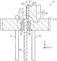
Fig. 2A is a schematic cross-sectional view (cross-sectional view taken along line 2-2 in fig. 3) showing the semiconductor device stem of fig. 1.
Fig. 2B is a partially enlarged sectional view of fig. 2A.
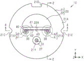
Fig. 3 is a schematic plan view showing the semiconductor device stem of fig. 1.
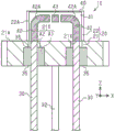
Fig. 4 is a schematic cross-sectional view of the semiconductor device stem of fig. 1 (a cross-sectional view taken along line 4-4 in fig. 3).
Fig. 5 is a schematic cross-sectional view showing a semiconductor device including the semiconductor device stem of fig. 1.
Fig. 6 is a graph showing reflection characteristics of the stem for a semiconductor device of fig. 1.
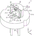
Fig. 7 is a schematic perspective view showing a semiconductor device according to a modification.
Fig. 8 is a schematic cross-sectional view showing a related art semiconductor device.
Description of the reference numerals
10 socket for semiconductor device
11 semiconductor device
20 island shape (base body)
21 main body part
21X through hole
22 heat dissipation part
22A mounting surface
30 signal lead wire (lead wire)
35 sealing element
36 air layer (cladding member)
40 wiring substrate
41 substrate
42 conductor pattern
43 conductor pattern (carrying part)
50 semiconductor element
60 joint part
70 cover
A1 opening part (1 st opening part)
A2 opening part (No. 2 opening part)
B1 projection
Detailed Description
An embodiment is described below with reference to the drawings.
In the drawings, for convenience, a portion to be a feature may be enlarged to easily understand the feature, and the dimensional ratio of each component is not necessarily the same as the actual one. In the sectional view, in order to make the sectional structure of each member easy to see, the hatching of some members is replaced with a satin pattern, and the hatching of some members is omitted.
As shown in fig. 1, a semiconductor device stem 10 (hereinafter referred to as a stem 10) includes an island-shaped body 20 as a base portion, signal leads (a plurality of) 30, monitoring leads (1) 31, ground leads (1) 32, and a wiring substrate 40. As the material of the signal lead 30, the monitor lead 31, and the ground lead 32, for example, an iron alloy such as kovar (kovar) or 52 alloy (alloy) can be used.
The island-like body 20 includes a main body 21 and a heat dissipation portion 22, and the heat dissipation portion 22 has a mounting surface 22A on which the wiring substrate 40 is mounted. These main body portion 21 and heat dissipation portion 22 are integrally formed. The main body 21 and the heat dissipation portion 22 function as heat dissipation plates for dissipating heat generated by the semiconductor element mounted on the stem 10. Therefore, the material of the main body 21 and the heat dissipation portion 22 is preferably a metal having good thermal conductivity. The main body 21 and the heat dissipation portion 22 are preferably made of materials having thermal expansion coefficients close to those of the wiring board 40 mounted on the mounting surface 22A and the semiconductor element mounted on the wiring board 40. As the material of the main body 21 and the heat radiating portion 22, iron, for example, can be used. The surfaces of the main body 21 and the heat dissipation portion 22 may be plated.
The main body 21 has a disc shape, for example. The diameter of the main body 21 can be set to about 5.6 to 9.0mm, for example. The thickness of the main body 21 can be set to about 1.0 to 2.0mm, for example. Here, in the present specification, the term "disc-like" refers to a shape having a planar shape of a substantially circular shape and having a predetermined thickness. In addition, in the "disc-like shape", there is no relation to the ratio of the thickness to the diameter. The shape in which the concave portion and the convex portion are partially formed is also included in the "disc shape".
In the outer edge of the main body 21, 2 notches 21C are formed in a shape recessed from the outer peripheral side toward the center side in a plan view. The notch 21C can be used, for example, for positioning a semiconductor element mounting surface when mounting a semiconductor element on the stem 10 (wiring board 40). The 2 recesses 21C are arranged, for example, oppositely. The planar shape of each notch 21C is, for example, a V shape.
Here, in the present specification, the "plan view" means that the object is viewed from the normal direction of the upper surface 21A of the body 21, and the "planar shape" means the shape of the object viewed from the normal direction of the upper surface 21A of the body 21. Hereinafter, the normal direction of the upper surface 21A of the main body 21 is referred to as the Z direction, the normal direction of the mounting surface 22A is referred to as the Y direction, and a direction orthogonal to both the Z direction and the Y direction is referred to as the X direction. For convenience of explanation, the side of the heat dissipation portion 22 located on the island 20 in the Z direction is referred to as an upper side, and the side opposite to the heat dissipation portion 22 with respect to the island 20 is referred to as a lower side. However, the semiconductor device stem 10 can be used in a state of being turned upside down, or can be disposed at an arbitrary angle.
A notch 21D having a shape recessed from the outer peripheral side toward the center side in a plan view is formed in the outer edge of the main body portion 21, and the notch 21D is different from the notch 21C. The recess 21D can be used for positioning in the rotational direction of the socket 10, for example. The planar shape of the notch 21D is, for example, a substantially U shape (see fig. 3). The notches 21C and 21D may be omitted as long as they are provided as necessary.
A through hole 21X is formed at a desired position (here, 2 positions) of the main body 21. The through hole 21X penetrates the body 21 in the thickness direction (Z direction). The 2 through holes 21X are arranged in the X direction at a predetermined interval.
As shown in fig. 2A, each through hole 21X extends from the upper surface 21A to the lower surface of the body 21. Each through hole 21X is defined by an opening a1 and an opening a2, and the opening a2 opens at the upper surface 21A of the body 21 and communicates with the opening a1, and has a planar shape smaller than the opening a 1. The openings a1 and a2 are, for example, substantially cylindrical, but the diameter of the opening a2 is smaller than the opening a 1. The opening a2 is disposed at a position overlapping the opening a1 in a plan view. The openings a1 and a2 are formed concentrically, for example. In this example, as shown in fig. 2B, the main body portion 21 includes a protruding portion B1, and the protruding portion B1 is located above the opening a1, protrudes from the upper outer edge of the opening a1 to the inside of the through hole 21X, and defines an opening a 2. In other words, the projection B1 is formed in a ring shape at a position overlapping the peripheral edge region of the opening a1 in a plan view, and the opening a2 is provided as an inner region surrounded by the projection B1. Thus, a step is formed inside the through hole 21X by the inner surface of the protruding portion B1 defining the opening a2, the lower surface of the protruding portion B1, and the inner surface of the body portion 21 defining the opening a 1.
As shown in fig. 2A, the signal lead 30 is, for example, substantially cylindrical. The diameter of the signal lead 30 can be set to, for example, about 0.15 to 0.6 mm. The signal lead 30 is inserted into the through hole 21X. Therefore, the axial direction of the signal lead 30 coincides with the thickness direction (Z direction) of the main body 21. The signal lead 30 includes: an upper end surface located on substantially the same plane as, for example, the upper surface 21A of the main body 21; and a lower end protruding downward from the lower surface of the body 21.
The signal lead 30 is sealed by the sealing material 35 in the opening a 1. That is, the sealing material 35 hermetically seals the opening a1, and fixes the signal lead 30 in the opening a1 (through hole 21X). In this example, the opening a1 is filled with the seal 35. Therefore, the gap between the inner wall surface of the body portion 21 defining the opening a1 and the outer peripheral surface of the signal lead 30 is filled with the sealing material 35, and the sealing material 39 and the outer peripheral surface of the signal lead 30 are in close contact with each other. The seal 35 is in contact with and covers the lower surface of the projection B1. The sealing material 35 has a function of securing an insulation distance between the signal lead 30 and the island 20 and a function of fixing the signal lead 30 in the through hole 21X. As a material of the sealing material 35, for example, glass or insulating resin can be used. As the glass, for example, a soft glass having a dielectric constant of about 6.7 can be used.
On the other hand, the sealing material 35 is not formed in the opening a2, and an air layer 36 as a covering material is formed in the opening a 2. Therefore, the signal lead 30 is exposed to the air having a dielectric constant of about 1 in the opening a 2. In other words, the opening a2 is filled with the air layer 36 (covering material) having a dielectric constant smaller than that of the sealing material 35 and covering the outer peripheral surface of the signal lead 30.
Here, the thermal expansion coefficient of the island 20 (iron in this example) is larger than that of the seal 35 (soft glass in this example). Therefore, the seal 35 is pinched by the island 20 due to the difference in the thermal expansion coefficient. Thus, the opening a1 is hermetically sealed by the seal 35, and the signal lead 30 is fixed to the island 20 in an insulated manner by the seal 35. As a result, a coaxial line is formed by the signal lead 30 and the seal 35. That is, the portion of the signal lead 30 inserted into the through hole 21X and sealed by the sealing material 35 functions as a coaxial line: the coaxial line has a signal lead wire 30 as a core wire.
In such a coaxial line, the characteristic impedance of the signal lead 30 can be adjusted to a desired value by appropriately adjusting the opening diameters (inner diameters) of the openings a1 and a2, the diameter (outer diameter) of the signal lead 30, the dielectric constant of the sealing material 35, and/or the dielectric constant of the covering material (if the covering material is the air layer 36, the dielectric constant of the covering material is about 1). In the stem 10 of the present example, the opening diameters of the openings a1 and a2 are appropriately adjusted so that the characteristic impedance of the signal lead 30 becomes a desired value (e.g., 25 Ω).
As shown in fig. 1, the heat dissipation portion 22 is erected on the upper surface 21A of the main body 21. The heat dissipation portion 22 is formed in a block shape, for example, and has a substantially semicircular shape in plan view. One side surface of the heat dissipation portion 22 is provided as a mounting surface 22A of the wiring substrate 40. The mounting surface 22A is a flat surface substantially perpendicular to the upper surface 21A of the main body 21 and parallel to the XZ plane. The semiconductor element is fixed to the wiring board 40 mounted on the mounting surface 22A.
As shown in fig. 3, the mounting surface 22A is formed to span 2 through holes 21X provided at a predetermined interval in the X direction. The heat dissipation portion 22 is provided at a position overlapping with a part of the opening a1 in a plan view and at a position not overlapping with the opening a2 in a plan view. In this example, the mounting surface 22A of the heat dissipation portion 22 is provided at a position that is separated from the center of each of the openings a1 and a2 by a distance that is shorter than the radius of the opening a1 and is equal to or greater than the radius of the opening a2 in a plan view.
As shown in fig. 4, the wiring board 40 mounted on the mounting surface 22A of the heat dissipation portion 22 includes a substrate 41 and conductor patterns 42 and 43 formed on a surface (front surface) of the substrate 41. The substrate 41 is, for example, a flat plate. For example, a material having high thermal conductivity and high electrical insulation is preferably used for the substrate 41. As a material of the substrate 41, for example, aluminum nitride (AlN) and aluminum oxide (Al) can be used2O3). The substrate 41 is formed so that the planar shape thereof viewed from the Y direction is smaller than the mounting surface 22A by one turn, for example. That is, in this example, the width (length in the X direction) of the substrate 41 is set to be shorter than the width of the mounting surface 22A. The height (length in the Z direction) of the substrate 41 is set to be lower than the height of the mounting surface 22A. The width of the substrate 41 can be set to about 2.4 to 2.8mm, for example, and the height of the substrate 41 can be set to about 1.2 to 1.4mm, for example. The thickness of the substrate 41 can be, for example, about 0.2 to 0.3 mm.
The conductor patterns 42, 43 are, for example, metallization patterns. The conductor patterns 42, 43 are spaced apart from each other. Each conductor pattern 42 corresponds to one of the signal leads 30. Each conductor pattern 42 is connected to the corresponding signal lead 30 when the wiring substrate 40 is joined to the mounting surface 22A of the heat sink portion 22. Each conductor pattern 42 is substantially L-shaped when viewed from the Y direction, for example. Each conductor pattern 42 extends from the lower end surface of the substrate 41 toward the upper portion of the substrate 41 where the conductor pattern 43 is located, in parallel with the axial direction (Z direction) of the signal lead 30. Each conductor pattern 42 includes a bent portion 42A bent at an upper portion (corner portion) of the substrate 41, and the tip of the bent portion 42A is close to the conductor pattern 43. Therefore, the bent portions 42A of the 2 conductor patterns 42 face each other with the conductor pattern 43 therebetween. The lower end surface of each conductor pattern 42 is exposed at the lower end surface of the substrate 41. For example, as shown in fig. 2B, the lower end surface of each conductor pattern 42 is flush with the lower end surface of the substrate 41. The width of the conductor pattern 42 can be set to, for example, about 0.2 to 0.3mm, and the thickness of the conductor pattern 42 can be set to, for example, about 0.001 to 0.003 mm.
As shown in fig. 4, the conductor pattern 43 is located between the 2 opposite bent portions 42A. In this example, the conductor pattern 43 is substantially rectangular as viewed from the Y direction. The conductor pattern 43 is provided as a mounting portion for a semiconductor element. The conductor pattern 43 is electrically connected to the island 20 by a conductor (not shown) penetrating the substrate 41, for example. Therefore, when the island 20 is at the ground potential, the conductor pattern 43 is also at the ground potential.
In the wiring board 40, the characteristic impedance of the conductor pattern 42 can be easily adjusted to a desired value. For example, the characteristic impedance of the conductor pattern 42 can be adjusted to a desired value by appropriately adjusting the dielectric constant of the substrate 41, the thickness of the substrate 41, and/or the width and thickness of the conductor pattern 42. In the wiring board 40, for example, a microstrip line structure in which a conductor layer having a ground potential is provided on the rear surface of the substrate 41 is formed, whereby the characteristic impedance of the conductor pattern 42 can be adjusted to a desired value.
The wiring substrate 40 is mounted on the island 20 by bonding the back surface of the substrate 41 to the mounting surface 22A. When the wiring board 40 is joined to the mounting surface 22A, the front surface of the wiring board 40 on which the conductor pattern 43 (mounting portion for a semiconductor element) is formed is substantially perpendicular to the upper surface 21A of the main body 21. The lower end surface of the substrate 41 abuts on the upper surface 21A of the body 21. In this example, as shown in fig. 3, the lower end surface of the substrate 41 abuts the upper surface 21A of the body 21 at a position between the position around each opening a2 and the position between the openings a 2. Therefore, the wiring board 40 is disposed so as to straddle 2 signal leads 30 spaced apart at a predetermined interval in the X direction. The front surface of the wiring substrate 40 on which the conductor pattern 42 is formed intersects the upper end surfaces of the signal leads 30. At this time, as shown in fig. 2A and 2B, the lower end surfaces of the conductor patterns 42 are substantially flush with the lower end surface of the substrate 41, so that the lower end surfaces of those conductor patterns 42 are respectively in contact with the upper end surfaces of the signal leads 30 located on substantially the same plane as the upper surface 21A of the main body 21. Thereby, the conductor pattern 42 is electrically connected to the signal lead 30.
In the stem 10 of the present example, the back surface of the substrate 41 is joined to the mounting surface 22A by soldering, and the lower end surface of the substrate 41 is joined to the upper surface 21A of the main body 21 by soldering. In the stem 10 of the present embodiment, the conductor patterns 42 are joined to the signal leads 30 by soldering, whereby the conductor patterns 42 are electrically connected to the signal leads 30 with reliability. In a state where the conductor patterns 42 and the signal leads 30 are electrically connected in this way, the wiring board 40 is mounted on the island 20.
The bonding and electrical connection between the conductor pattern 42 and the signal lead 30 is not limited to soldering, and a conductive adhesive may be used instead of soldering. When the conductor pattern 42 and the signal lead 30 are joined by soldering or the like, it is necessary to prevent the conductor pattern 42 and the signal lead 30 from being electrically short-circuited with the island 20.
As shown in fig. 1, through holes 21Y are formed at desired positions (1 position in this case) of the main body 21. The through hole 21Y penetrates the body 21 in the thickness direction. In this example, no step portion is formed inside the through hole 21Y. Similarly to the openings a1 and a2 of the through hole 21X, a stepped portion may be formed inside the through hole 21Y.
The monitor lead 31 is inserted into the through hole 21Y. Therefore, the axial direction of the monitoring lead 31 coincides with the thickness direction (Z direction) of the main body 21. The monitoring lead 31 is sealed by a sealing material 37 in the through hole 21Y. That is, the sealing material 37 hermetically seals the through hole 21Y, and the monitoring lead 31 is fixed in the through hole 21Y. The monitor lead wire 31 is, for example, substantially cylindrical. In this example, the upper portion of the monitoring lead 31 protrudes upward from the upper surface 21A of the main body 21. The lower portion of the monitoring lead 31 protrudes downward from the lower surface of the body 21. As the material of the seal 37, the same material as that of the seal 35 (see fig. 2A) can be used.
As shown in fig. 2A, the ground lead 32 extends downward from the lower surface of the body 21. The ground lead 32 is joined to the lower surface of the body 21 by, for example, soldering and is electrically connected to the body 21. Therefore, when the ground lead 32 is grounded, the island 20 (the main body 21 and the heat dissipation portion 22) is also grounded. In this case, the heat dissipation portion 22 also functions as a ground portion set to a ground potential. The ground lead 32 is, for example, substantially cylindrical. The axial direction of the ground lead 32 coincides with the Z direction.
The stem 10 can be manufactured by the following method, for example. The main body 21 and the heat dissipation portion 22 of the island-shaped body 20 can be integrally formed by press working using a cold press, for example. In this case, since the heat dissipation portion 22 is disposed at a position not overlapping with the opening a2 in a plan view, both the main body 21 including the through hole 21X (the openings a1 and a2) and the heat dissipation portion 22 can be formed by press working.
Next, when the sealing material 35 is made of glass, for example, glass powder is molded into a cylindrical molded body having the shape of the sealing material 35 by a known powder press method or an extrusion molding method. The cylindrical molded body has an inner diameter (bore diameter) corresponding to the diameter of the signal lead 30 and an outer diameter corresponding to the diameter of the opening a 1. Next, the cylindrical molded body is inserted into the opening a1, and the signal lead 30 is inserted into the hole of the cylindrical molded body. After the sealing material 35 (cylindrical molded body) is heated to a predetermined temperature and melted, the sealing material 35 is cooled and solidified. Thus, the signal lead 30 is sealed and fixed by the sealing material 35 in the opening a1 in a state of being insulated from the island 20. In this step, since the glass is heated and melted to conform to a predetermined shape (the shape of the seal 35) and then the glass must be changed into a spherical shape, a free surface which is not a horizontal surface but a curved surface is formed, and therefore, as shown in fig. 2B, a gap S1 is generated in the end surface (in this example, the upper end surface) of the seal 35 in the opening a 1. At this time, since a part of the upper end surface of the seal 35 is pressed by the lower surface of the projection B1, only a part of the upper end surface of the seal 35 becomes a free surface. Therefore, as compared with the case where the seal 135 is formed in the through-hole 121X having no step portion (protruding portion B1) as in the semiconductor device 100 of fig. 8, the free surface of the seal 35 can be made smaller, and as a result, the volume of the space S1 filled with air having a dielectric constant of about 1 can be made smaller. For example, when the opening a1 has the same opening diameter as the through hole 121X in fig. 8, the volume of the space S1 formed in the seal 35 in the opening a1 can be made smaller than the volume of the space S2 formed in the seal 135 in the through hole 121X. This can suppress variations in the characteristic impedance of the signal lead 30 due to the gap S1 to a small level, and can suppress a mismatch in the characteristic impedance of the connection portion between the signal lead 30 and the conductor pattern 42 to a small level.
Next, after the conductor pattern 42 of the wiring substrate 40 is aligned with the signal lead 30, the wiring substrate 40 is joined to the mounting surface 22A of the heat dissipation portion 22 and the upper surface 21A of the main body portion 21 by soldering or the like. The signal lead 30 and the conductor pattern 42 are simultaneously connected by soldering or the like. After the wiring substrate 40 is bonded to the island-shaped body 20, the signal lead 30 and the conductor pattern 42 may be connected.
By the above manufacturing method, the semiconductor device stem 10 shown in fig. 1 can be manufactured.
Next, a structure of the semiconductor device 11 in which the semiconductor element 50 is mounted on the stem 10 will be described with reference to fig. 5.
The semiconductor element 50 is fixed to the surface of the conductor pattern 43 of the wiring substrate 40 with the light emitting surface (upper end surface in this case) facing upward, for example. In this case, the semiconductor element 50 is mounted on the stem 10 such that the light emitting point of the semiconductor element 50 substantially coincides with the center of the upper surface 21A of the main body 21 in a plan view. An electrode (not shown) of semiconductor element 50 is electrically connected to conductor pattern 42 by, for example, bonding wire 51. Thereby, the signal lead 30 is electrically connected to the semiconductor element 50 by the conductor pattern 42. For example, a ground electrode (not shown) is formed on the rear surface of the semiconductor element 50, and when the semiconductor element 50 is mounted on the conductor pattern 43, the ground electrode is electrically connected to the conductor pattern 43.
The bonding portion 60 is formed on the upper surface 21A of the main body 21 so as to surround the heat dissipation portion 22, the signal lead 30, and the monitoring lead 31 (see fig. 1). The joint 60 is, for example, substantially annular. For example, a metal layer in which a nickel (Ni) layer and a gold (Au) layer having excellent corrosion resistance are sequentially laminated can be used for the bonding portion 60. The Ni layer and the Au layer can be formed by, for example, an electroplating method.
The cover 70 is in the shape of a hollow cap. The lid 70 includes a substantially cylindrical lid main body 71, and the lid main body 71 has a top plate portion, and an opening (window) 71X is formed substantially in the center of the top plate portion in a plan view. The cover 70 includes a transparent member 74 below the opening 71X, and the transparent member 74 is bonded to the cover main body 71 with an adhesive 73. The gap between the top plate portion of the lid main body portion 71 and the periphery of the transparent member 74 is filled with an adhesive 73, whereby the lid 70 is sealed from the external environment passing through the opening 71X. The cap 70 includes an annular (in this example, annular) flange 72 formed by bending the outer periphery of the bottom of the cap body 71 outward. The lower surface of the flange 72 is joined to the joining portion 60, whereby the cover 70 is joined to the island 20. Thereby, the inside of the cover 70 that houses the semiconductor element 50 fixed to the wiring substrate 40 is hermetically sealed. The lid 70 can be joined to the joint portion 60 by resistance welding, for example.
As a material of the lid main body portion 71, a metal such as iron or copper, or an alloy containing at least one of those metals can be used. As the material of the adhesive 73, for example, low-melting glass can be used. The material of the transparent member 74 can use, for example, glass. The opening 71X of the cover 70, the adhesive 73, and the transparent member 74 may be omitted. The joint 60 may be omitted, and the cover 70 may be directly joined to the upper surface 21A of the body 21 by welding or the like.
In the semiconductor device 11 described above, light emitted from the light emitting surface (upper end surface in this example) of the semiconductor element 50 is transmitted through the transparent member 74 and emitted from the opening 71X in the Z direction (upward in this example).
Next, the operation of the semiconductor device 11 will be described.
In the semiconductor device 11, the signal lead 30 sealed by the sealing material 35 in the through hole 21X is electrically connected to the conductor pattern 42 of the wiring board 40, and the conductor pattern 42 is electrically connected to the semiconductor element 50 by the bonding wire 51. Thereby, the upper end portion of the signal lead 30 is electrically connected to the semiconductor element 50 by the conductor pattern 42. The lower end of the signal lead 30 is electrically connected to, for example, an external circuit (not shown). Thus, the signal lead 30 functions to transmit a high-frequency input/output signal between the semiconductor element 50 and an external circuit. At this time, the portion of the signal lead 30 sealed by the sealing material 35 in the through hole 21X is provided as a coaxial line (coaxial structure). Therefore, by adjusting the diameter of the signal lead 30, the opening diameters of the openings a1 and a2, the dielectric constant of the sealing material 35, and/or the dielectric constant of the covering material (in this example, the air layer 36), the characteristic impedance of the signal lead 30 can be easily adjusted. For example, by appropriately adjusting the opening diameters of the openings a1 and a2, the characteristic impedance of the signal lead 30 can be matched to a desired characteristic impedance value (for example, the characteristic impedance of a circuit or the like formed on the semiconductor element 50), for example, 25 Ω. Further, the characteristic impedance of the conductor pattern 42 electrically connecting the signal lead 30 and the semiconductor element 50 can be easily adjusted to a desired value as described above. This enables matching of the characteristic impedance value of the entire transmission line in the semiconductor device 11. As a result, reflection loss of the high-frequency signal can be reduced, and transmission characteristics of the high-frequency signal can be maintained well.
For example, when the dielectric constant of the sealing material 35 is 6.7 and the diameter of the signal lead 30 is 0.32mm, the characteristic impedance of the signal lead 30 can be matched to 25 Ω in the opening a1 by setting the opening diameter of the opening a1 to 0.93 mm. When the dielectric constant of the air layer 36 is 1 and the diameter of the signal lead 30 is 0.32mm, the characteristic impedance of the signal lead 30 can be matched to 25 Ω in the opening a2 by setting the opening diameter of the opening a2 to 0.48 mm. Here, since the dielectric constant of the air layer 36 is smaller than that of the sealing material 35, the opening diameter of the opening a2 can be set smaller than that of the opening a 1. In the wiring board 40, the characteristic impedance of the conductor pattern 42 can be matched to 25 Ω by setting the thickness of the substrate 41 made of aluminum nitride having a dielectric constant of 8.7 to 0.3mm, the width of the conductor pattern 42 to 0.3mm, and the thickness of the conductor pattern 42 to 0.002 mm.
In the semiconductor device 11, the distance from the center of each of the openings a1 and a2 to the mounting surface 22A in a plan view is set to be shorter than the radius (0.465mm) of the opening a1 and equal to or longer than the radius (0.24mm) of the opening a 2. For example, when the distance is set to 0.3mm, the heat dissipation portion 22 projects 0.165mm above the opening a1 having a diameter of 0.93mm, and the heat dissipation portion 22 is spaced 0.06mm from the opening end of the opening a2 having a diameter of 0.48 mm. In this way, the mounting surface 22A can be brought close to the center of each of the openings a1 and a2 within a range where the heat dissipation portion 22 does not protrude above the opening a 2. This can suppress an increase in the thickness of the substrate 41 and appropriately connect the lower end surface of the conductor pattern 42 formed on the front surface of the substrate 41 to the upper end surface of the signal lead 30. Further, since the heat dissipation portion 22 does not protrude above the opening a2, the main body portion 21 including the through holes 21X and 21Y and the heat dissipation portion 22 can be formed together by press working.
Fig. 6 shows characteristic changes due to impedance mismatch when the stem 10 is connected to an impedance port of 25 Ω in order to verify transmission characteristics of a high-frequency signal of the stem 10 for a semiconductor device. Specifically, fig. 6 shows the frequency characteristics of the reflected signal with respect to the input signal.
As is clear from the simulation results in fig. 6, the reflection loss of the input signal can be suppressed to be small in the semiconductor device stem 10. Specifically, even when the frequency of the input signal is 20GHz or more, the reflection characteristic S11 can be suppressed to a small value of-20 dB or less. From the results, it is understood that the semiconductor device stem 10 can maintain good transmission characteristics of high-frequency signals.
The above embodiment has the following advantages.
(1) The island-shaped body 20 (base portion) of the semiconductor device stem 10 includes a main body portion 21 and a heat dissipation portion 22. The signal lead 30 is inserted into the through hole 21X, and the through hole 21X penetrates the body 21 in the thickness direction. The through hole 21X is defined by an opening a1 and an opening a2, and the opening a2 opens at the upper surface 21A of the body 21 and has a planar shape smaller than the opening a 1. The heat dissipation portion 22 having the mounting surface 22A is provided at a position overlapping with a part of the opening a1 in a plan view and not overlapping with the opening a2 in a plan view. This enables the main body 21 including the through hole 21X and the heat dissipation portion 22 to be formed together by press working. Therefore, the manufacturing cost of the semiconductor device stem 10 can be reduced.
(2) The mounting surface 22A can be brought close to the center of each of the openings a1 and a2 within a range where the heat dissipation portion 22 does not protrude above the opening a 2. This can suppress an increase in the thickness of the substrate 41 and appropriately connect the lower end surface of the conductor pattern 42 to the upper end surface of the signal lead 30. Further, the wiring substrate 40 can be directly bonded to the mounting surface 22A without interposing another member such as a spacer between the wiring substrate 40 and the mounting surface 22A. Therefore, the number of components can be reduced as compared with the semiconductor device 100 of fig. 8, and the manufacturing cost of the semiconductor device stem 10 can be reduced. Further, since the wiring substrate 40 can be directly bonded to the mounting surface 22A, the mounting accuracy of the wiring substrate 40 can be improved.
(3) A part of the upper end surface of the seal member 35 is in contact with the lower surface of the projection B1. This can reduce the volume of the space S1 formed in the seal 35 in the opening a 1. Therefore, variations in the characteristic impedance of the signal lead 30 due to the gap S1 can be suppressed to be small, and mismatch in the characteristic impedance of the connection portion between the signal lead 30 and the conductor pattern 42 can be suppressed to be small.
(4) The characteristic impedance of the entire transmission line in the semiconductor device 11 can be matched. As a result, reflection loss of the high-frequency signal can be reduced, and transmission characteristics of the high-frequency signal can be maintained well.
The above embodiment can also be implemented by the following embodiment appropriately modified.
In the above embodiment, 1 semiconductor element 50 is mounted on the stem 10 including 2 through holes 21X. Not limited to this, a plurality of semiconductor elements may be mounted on the stem 10, and the number of the through holes 21X and the number of the signal leads 30 may be changed according to the number of the mounted semiconductor elements and the number of the terminals of the semiconductor elements.
For example, as shown in fig. 7, 2 semiconductor elements 50 and 55 may be mounted on the stem 10. For example, a light emitting element can be used as the semiconductor element 50, and a light receiving element can be used as the semiconductor element 55. The light receiving element can be, for example, a photodiode. A recess 21Z for mounting semiconductor element 55 is formed in upper surface 21A of main body 21. In this example, the concave portion 21Z is provided at a position between the 2 through holes 21X and in the vicinity of the conductor pattern 43 (mounting portion of the semiconductor element 50) in a plan view. The bottom surface of the recess 21Z is formed as an inclined surface that is inclined downward from the front surface side of the wiring substrate 40 toward the outer edge side of the main body 21, for example. Semiconductor element 55 is mounted on the inclined surface (bottom surface) of recess 21Z. The electrodes (not shown) of the semiconductor element 55 are electrically connected to the signal leads 30 by, for example, bonding wires or conductor patterns formed on the wiring board 40.
In the semiconductor device 11 shown in fig. 7, light emitted from the upper end surface of the semiconductor element 50 (light-emitting element) is emitted in the Z direction (upward in this case). The light emitted from the lower end surface of the semiconductor element 50 is received by the semiconductor element 55 (light receiving element). For example, the amount of light emitted from the semiconductor element 50 is monitored by the semiconductor element 55, and the amount of light received by the semiconductor element 55 is controlled to be constant by a circuit disposed outside the semiconductor device 11, whereby the amount of light emitted from the semiconductor device 11 can be made constant regardless of the ambient temperature or the like.
In the above embodiment, the air layer 36 is formed in the opening a 2. Not limited to this, a covering material made of a material having a smaller dielectric constant than that of the sealing material 35 (a material other than air) may be filled in the opening a 2.
The shapes of the conductor patterns 42 and 43 in the above embodiments are not particularly limited.
The conductor pattern 43 in the above embodiment may be omitted.
As the substrate 41 of the above embodiment, a resin substrate such as a glass epoxy substrate may be used.
In the above embodiment, the upper end surface of the signal lead 30 is located on substantially the same plane as the upper surface 21A of the main body 21. Without being limited thereto, the position of the upper end face of the signal lead 30 is not particularly limited if the signal lead 30 and the conductor pattern 42 can be electrically connected. For example, the upper end surface of the signal lead 30 may protrude upward from the upper surface 21A of the main body 21.
In the above embodiment, the signal lead 30 is formed in a substantially cylindrical shape. The signal lead 30 may be formed in a polygonal column shape such as a triangular column shape or a rectangular column shape, or an elliptic column shape.
In the above embodiment, the openings a1 and a2 are formed in a substantially cylindrical shape. The openings a1 and a2 may be formed in a polygonal column shape such as a triangular column shape or a rectangular column shape, or an elliptical column shape. In this case, the openings a1 and a2 are preferably the same shape as the signal lead 30.
The through hole 21Y, the monitoring lead 31, and the sealing material 37 in the above embodiment may be omitted.
Claims (5)
1. A semiconductor device stem is characterized by comprising a base body portion, a through hole, a lead, a sealing material, a covering material, and a wiring board,
the base portion includes: a main body portion; and a heat dissipating unit which is erected on the upper surface of the main body and is formed integrally with the main body,
the through hole is defined by a1 st opening and a2 nd opening, penetrates the body portion in the thickness direction, the 2 nd opening opens on the upper surface of the body portion, communicates with the 1 st opening, and has a planar shape smaller than the 1 st opening,
the lead wire is inserted into the through-hole,
the sealing material fills the 1 st opening to seal the lead,
the covering member fills the 2 nd opening portion and has a dielectric constant smaller than that of the sealing member,
the wiring board includes a conductor pattern electrically connected to the lead and a mounting portion on which a semiconductor element is mounted, and is joined to a mounting surface of the heat dissipating portion,
the mounting surface of the heat dissipation portion is provided at a position overlapping with a part of the 1 st opening in a plan view and not overlapping with the 2 nd opening in a plan view,
the upper end surface of the lead and the upper surface of the main body portion are located on the same plane,
the lower end surface of the wiring substrate is abutted against the upper surface of the main body,
the lower end surface of the conductor pattern is connected to the upper end surface of the lead.
2. The header for semiconductor devices of claim 1, wherein,
the main body portion includes a protruding portion which is located above the 1 st opening and which protrudes from an upper outer edge of the 1 st opening toward an inner side of the through hole to define the 2 nd opening,
the seal is formed in the 1 st opening so as to be in contact with the lower surface of the projection.
3. The stem for a semiconductor device according to claim 1, wherein the coating member is an air layer.
4. The stem for semiconductor device according to any one of claims 1 to 3, wherein an opening diameter of the 1 st opening and an opening diameter of the 2 nd opening are set so that a characteristic impedance of the lead becomes a desired value.
5. A semiconductor device is characterized by comprising:
the stem for a semiconductor device according to any one of claims 1 to 4;
a semiconductor element mounted on the mounting portion of the wiring board and electrically connected to the conductor pattern; and
a cap engaged with the main body portion of the stem.
Applications Claiming Priority (2)
| Application Number | Priority Date | Filing Date | Title |
|---|---|---|---|
| JP2015110330A JP6614811B2 (en) | 2015-05-29 | 2015-05-29 | Semiconductor device stem and semiconductor device |
| JP2015-110330 | 2015-05-29 |
Publications (2)
| Publication Number | Publication Date |
|---|---|
| CN106206465A CN106206465A (en) | 2016-12-07 |
| CN106206465B true CN106206465B (en) | 2020-09-11 |
Family
ID=57397231
Family Applications (1)
| Application Number | Title | Priority Date | Filing Date |
|---|---|---|---|
| CN201610357001.0A Active CN106206465B (en) | 2015-05-29 | 2016-05-26 | Semiconductor device header and semiconductor device |
Country Status (3)
| Country | Link |
|---|---|
| US (1) | US20160352069A1 (en) |
| JP (1) | JP6614811B2 (en) |
| CN (1) | CN106206465B (en) |
Families Citing this family (15)
| Publication number | Priority date | Publication date | Assignee | Title |
|---|---|---|---|---|
| JP6678007B2 (en) * | 2015-11-05 | 2020-04-08 | 新光電気工業株式会社 | Optical element package, method of manufacturing the same, and optical element device |
| JP6715601B2 (en) * | 2016-01-08 | 2020-07-01 | 新光電気工業株式会社 | Optical semiconductor device package |
| JP6929113B2 (en) * | 2017-04-24 | 2021-09-01 | 日本ルメンタム株式会社 | Optical assemblies, optical modules, and optical transmission equipment |
| JP7181699B2 (en) * | 2018-04-10 | 2022-12-01 | ローム株式会社 | Semiconductor laser device |
| JP7245620B2 (en) * | 2018-08-03 | 2023-03-24 | 日本ルメンタム株式会社 | Optical subassemblies and optical modules |
| JP7249745B2 (en) * | 2018-08-03 | 2023-03-31 | 日本ルメンタム株式会社 | Optical subassemblies and optical modules |
| US20210257808A1 (en) * | 2018-11-21 | 2021-08-19 | Mitsubishi Electric Corporation | Optical module |
| JP2022046833A (en) * | 2019-01-31 | 2022-03-24 | 京セラ株式会社 | Package for mounting electronic component and electronic apparatus |
| CN113474883B (en) * | 2019-02-28 | 2023-11-03 | 京瓷株式会社 | Package for mounting electronic component and electronic device |
| JP7398877B2 (en) | 2019-04-18 | 2023-12-15 | 新光電気工業株式会社 | Stems for semiconductor devices and semiconductor devices |
| JP2021027136A (en) * | 2019-08-02 | 2021-02-22 | CIG Photonics Japan株式会社 | Optical module |
| JP2022185157A (en) * | 2019-10-25 | 2022-12-14 | 京セラ株式会社 | Package for mounting electronic component, electronic device, and electronic module |
| JPWO2021166073A1 (en) * | 2020-02-18 | 2021-08-26 | ||
| JP7382871B2 (en) | 2020-03-24 | 2023-11-17 | 新光電気工業株式会社 | Stem for semiconductor packages, semiconductor packages |
| JP7382872B2 (en) * | 2020-03-24 | 2023-11-17 | 新光電気工業株式会社 | Stem for semiconductor packages, semiconductor packages |
Citations (4)
| Publication number | Priority date | Publication date | Assignee | Title |
|---|---|---|---|---|
| JP2004134697A (en) * | 2002-10-15 | 2004-04-30 | Shinko Electric Ind Co Ltd | Glass terminal |
| JP2007048937A (en) * | 2005-08-10 | 2007-02-22 | Rohm Co Ltd | Semiconductor laser and manufacturing method thereof |
| JP2011134740A (en) * | 2009-12-22 | 2011-07-07 | Kyocera Corp | Package for mounting electronic component, and electronic device using the same |
| CN103907249A (en) * | 2011-11-30 | 2014-07-02 | 松下电器产业株式会社 | Nitride semiconductor light-emitting device |
Family Cites Families (12)
| Publication number | Priority date | Publication date | Assignee | Title |
|---|---|---|---|---|
| JP3226183B2 (en) * | 1991-11-27 | 2001-11-05 | 新光電気工業株式会社 | Coaxial line of high frequency element package |
| JPH11186425A (en) * | 1997-12-24 | 1999-07-09 | Sharp Corp | High frequency module device |
| KR100480253B1 (en) * | 2002-12-27 | 2005-04-07 | 삼성전자주식회사 | Optical module |
| US7196389B2 (en) * | 2005-02-14 | 2007-03-27 | Mitsubishi Denki Kabushiki Kaisha | Optical semiconductor device package and optical semiconductor device |
| JP4923542B2 (en) * | 2005-11-30 | 2012-04-25 | 三菱電機株式会社 | Optical element stem and optical semiconductor device using the same |
| JP4856465B2 (en) * | 2006-04-19 | 2012-01-18 | 日本オプネクスト株式会社 | Optical semiconductor element mounting substrate and optical transmission module |
| JP5004824B2 (en) * | 2007-08-29 | 2012-08-22 | 京セラ株式会社 | Connection structure between signal terminal and signal line conductor, electronic component mounting package and electronic device |
| JP5079474B2 (en) * | 2007-11-29 | 2012-11-21 | シャープ株式会社 | Cap member and semiconductor device using the same |
| JP5312358B2 (en) * | 2009-04-24 | 2013-10-09 | 京セラ株式会社 | Electronic component mounting package and electronic device using the same |
| JP2011061750A (en) * | 2009-09-15 | 2011-03-24 | Nippon Telegr & Teleph Corp <Ntt> | Connection method and structure for high-frequency line, and package having the structure |
| JP5338711B2 (en) * | 2010-02-23 | 2013-11-13 | Tdk株式会社 | Magnetic sensor, magnetic detection device, and magnetic head |
| CN103222045B (en) * | 2010-11-29 | 2016-04-27 | 京瓷株式会社 | Electro part carrying packaging body and make use of the electronic installation of this packaging body |
-
2015
- 2015-05-29 JP JP2015110330A patent/JP6614811B2/en active Active
-
2016
- 2016-05-26 US US15/165,335 patent/US20160352069A1/en not_active Abandoned
- 2016-05-26 CN CN201610357001.0A patent/CN106206465B/en active Active
Patent Citations (4)
| Publication number | Priority date | Publication date | Assignee | Title |
|---|---|---|---|---|
| JP2004134697A (en) * | 2002-10-15 | 2004-04-30 | Shinko Electric Ind Co Ltd | Glass terminal |
| JP2007048937A (en) * | 2005-08-10 | 2007-02-22 | Rohm Co Ltd | Semiconductor laser and manufacturing method thereof |
| JP2011134740A (en) * | 2009-12-22 | 2011-07-07 | Kyocera Corp | Package for mounting electronic component, and electronic device using the same |
| CN103907249A (en) * | 2011-11-30 | 2014-07-02 | 松下电器产业株式会社 | Nitride semiconductor light-emitting device |
Also Published As
| Publication number | Publication date |
|---|---|
| JP2016225457A (en) | 2016-12-28 |
| CN106206465A (en) | 2016-12-07 |
| JP6614811B2 (en) | 2019-12-04 |
| US20160352069A1 (en) | 2016-12-01 |
Similar Documents
| Publication | Publication Date | Title |
|---|---|---|
| CN106206465B (en) | Semiconductor device header and semiconductor device | |
| US7875901B2 (en) | Optical device package and optical semiconductor device using the same | |
| JP4550386B2 (en) | Package for optical semiconductor devices | |
| US11153962B2 (en) | Header for semiconductor device, and semiconductor device | |
| CN113474883B (en) | Package for mounting electronic component and electronic device | |
| WO2020262636A1 (en) | Electronic component mounting package, and electronic device | |
| US9983363B2 (en) | Optical semiconductor device | |
| JP7036646B2 (en) | Packages for semiconductor devices and semiconductor devices | |
| JP5519432B2 (en) | High frequency package | |
| JP5121421B2 (en) | Optical semiconductor device package and optical semiconductor device | |
| US20240072512A1 (en) | Optical semiconductor device | |
| US20240047936A1 (en) | Electronic component package and the manufacturing method thereof | |
| US20230344193A1 (en) | Stem for semiconductor package and semiconductor package | |
| JP6671567B1 (en) | Optical module | |
| JP6408661B2 (en) | TO-CAN type package header and semiconductor device | |
| JP2009182251A (en) | Optical reception sub assembly and optical reception module | |
| JP2015122466A (en) | Header for to-can type package and semiconductor device | |
| KR20230002068A (en) | Header for semiconductor package, and semiconductor package | |
| JP2022046833A (en) | Package for mounting electronic component and electronic apparatus | |
| JP2019041045A (en) | Package for electronic component housing and electronic device |
Legal Events
| Date | Code | Title | Description |
|---|---|---|---|
| C06 | Publication | ||
| PB01 | Publication | ||
| SE01 | Entry into force of request for substantive examination | ||
| SE01 | Entry into force of request for substantive examination | ||
| GR01 | Patent grant | ||
| GR01 | Patent grant |