CN1051284C - Coating film transfer tool - Google Patents
Coating film transfer tool Download PDFInfo
- Publication number
- CN1051284C CN1051284C CN94112844A CN94112844A CN1051284C CN 1051284 C CN1051284 C CN 1051284C CN 94112844 A CN94112844 A CN 94112844A CN 94112844 A CN94112844 A CN 94112844A CN 1051284 C CN1051284 C CN 1051284C
- Authority
- CN
- China
- Prior art keywords
- filming
- around
- transition zone
- coating film
- film transfer
- Prior art date
- Legal status (The legal status is an assumption and is not a legal conclusion. Google has not performed a legal analysis and makes no representation as to the accuracy of the status listed.)
- Expired - Lifetime
Links
- 238000012546 transfer Methods 0.000 title claims abstract description 90
- 239000011248 coating agent Substances 0.000 title claims abstract description 47
- 238000000576 coating method Methods 0.000 title claims abstract description 47
- 230000007704 transition Effects 0.000 claims description 102
- 238000004804 winding Methods 0.000 claims description 20
- 238000012937 correction Methods 0.000 claims description 10
- 230000004807 localization Effects 0.000 claims description 10
- 239000003795 chemical substances by application Substances 0.000 claims description 7
- 229920003023 plastic Polymers 0.000 claims description 7
- 239000004033 plastic Substances 0.000 claims description 7
- 239000000853 adhesive Substances 0.000 claims description 6
- 230000001070 adhesive effect Effects 0.000 claims description 6
- 210000002469 basement membrane Anatomy 0.000 claims description 5
- 230000007246 mechanism Effects 0.000 claims description 5
- 239000000463 material Substances 0.000 claims description 3
- 230000009471 action Effects 0.000 description 12
- 230000005540 biological transmission Effects 0.000 description 10
- 230000008859 change Effects 0.000 description 8
- 230000000694 effects Effects 0.000 description 7
- 238000000034 method Methods 0.000 description 6
- 230000035807 sensation Effects 0.000 description 5
- 230000006870 function Effects 0.000 description 4
- 230000000977 initiatory effect Effects 0.000 description 4
- 206010040007 Sense of oppression Diseases 0.000 description 3
- 230000004048 modification Effects 0.000 description 3
- 238000012986 modification Methods 0.000 description 3
- 229920002379 silicone rubber Polymers 0.000 description 3
- 230000015572 biosynthetic process Effects 0.000 description 2
- 210000000078 claw Anatomy 0.000 description 2
- 150000001875 compounds Chemical class 0.000 description 2
- 229920002457 flexible plastic Polymers 0.000 description 2
- 239000011888 foil Substances 0.000 description 2
- 230000008569 process Effects 0.000 description 2
- 230000001360 synchronised effect Effects 0.000 description 2
- QTBSBXVTEAMEQO-UHFFFAOYSA-M Acetate Chemical compound CC([O-])=O QTBSBXVTEAMEQO-UHFFFAOYSA-M 0.000 description 1
- 239000004821 Contact adhesive Substances 0.000 description 1
- 239000004698 Polyethylene Substances 0.000 description 1
- 229920002433 Vinyl chloride-vinyl acetate copolymer Polymers 0.000 description 1
- 230000006578 abscission Effects 0.000 description 1
- 230000003321 amplification Effects 0.000 description 1
- 238000013459 approach Methods 0.000 description 1
- 229920006026 co-polymeric resin Polymers 0.000 description 1
- 239000000470 constituent Substances 0.000 description 1
- 239000012467 final product Substances 0.000 description 1
- 239000002783 friction material Substances 0.000 description 1
- 230000006872 improvement Effects 0.000 description 1
- 238000002347 injection Methods 0.000 description 1
- 239000007924 injection Substances 0.000 description 1
- 238000003780 insertion Methods 0.000 description 1
- 230000037431 insertion Effects 0.000 description 1
- 238000009434 installation Methods 0.000 description 1
- 239000004922 lacquer Substances 0.000 description 1
- 210000004379 membrane Anatomy 0.000 description 1
- 239000012528 membrane Substances 0.000 description 1
- 238000003199 nucleic acid amplification method Methods 0.000 description 1
- 230000002093 peripheral effect Effects 0.000 description 1
- 229920006267 polyester film Polymers 0.000 description 1
- -1 polyethylene Polymers 0.000 description 1
- 229920000573 polyethylene Polymers 0.000 description 1
- 229920002635 polyurethane Polymers 0.000 description 1
- 239000004814 polyurethane Substances 0.000 description 1
- 238000011084 recovery Methods 0.000 description 1
- 229920005989 resin Polymers 0.000 description 1
- 239000011347 resin Substances 0.000 description 1
- 238000007493 shaping process Methods 0.000 description 1
- 230000036962 time dependent Effects 0.000 description 1
- 125000000391 vinyl group Chemical group [H]C([*])=C([H])[H] 0.000 description 1
- 229920002554 vinyl polymer Polymers 0.000 description 1
Images


Classifications
-
- B—PERFORMING OPERATIONS; TRANSPORTING
- B65—CONVEYING; PACKING; STORING; HANDLING THIN OR FILAMENTARY MATERIAL
- B65H—HANDLING THIN OR FILAMENTARY MATERIAL, e.g. SHEETS, WEBS, CABLES
- B65H35/00—Delivering articles from cutting or line-perforating machines; Article or web delivery apparatus incorporating cutting or line-perforating devices, e.g. adhesive tape dispensers
- B65H35/04—Delivering articles from cutting or line-perforating machines; Article or web delivery apparatus incorporating cutting or line-perforating devices, e.g. adhesive tape dispensers from or with transverse cutters or perforators
- B65H35/06—Delivering articles from cutting or line-perforating machines; Article or web delivery apparatus incorporating cutting or line-perforating devices, e.g. adhesive tape dispensers from or with transverse cutters or perforators from or with blade, e.g. shear-blade, cutters or perforators
-
- B—PERFORMING OPERATIONS; TRANSPORTING
- B65—CONVEYING; PACKING; STORING; HANDLING THIN OR FILAMENTARY MATERIAL
- B65H—HANDLING THIN OR FILAMENTARY MATERIAL, e.g. SHEETS, WEBS, CABLES
- B65H37/00—Article or web delivery apparatus incorporating devices for performing specified auxiliary operations
- B65H37/002—Web delivery apparatus, the web serving as support for articles, material or another web
- B65H37/005—Hand-held apparatus
- B65H37/007—Applicators for applying coatings, e.g. correction, colour or adhesive coatings
-
- B—PERFORMING OPERATIONS; TRANSPORTING
- B43—WRITING OR DRAWING IMPLEMENTS; BUREAU ACCESSORIES
- B43L—ARTICLES FOR WRITING OR DRAWING UPON; WRITING OR DRAWING AIDS; ACCESSORIES FOR WRITING OR DRAWING
- B43L19/00—Erasers, rubbers, or erasing devices; Holders therefor
-
- Y—GENERAL TAGGING OF NEW TECHNOLOGICAL DEVELOPMENTS; GENERAL TAGGING OF CROSS-SECTIONAL TECHNOLOGIES SPANNING OVER SEVERAL SECTIONS OF THE IPC; TECHNICAL SUBJECTS COVERED BY FORMER USPC CROSS-REFERENCE ART COLLECTIONS [XRACs] AND DIGESTS
- Y10—TECHNICAL SUBJECTS COVERED BY FORMER USPC
- Y10T—TECHNICAL SUBJECTS COVERED BY FORMER US CLASSIFICATION
- Y10T156/00—Adhesive bonding and miscellaneous chemical manufacture
- Y10T156/17—Surface bonding means and/or assemblymeans with work feeding or handling means
- Y10T156/1788—Work traversing type and/or means applying work to wall or static structure
- Y10T156/1795—Implement carried web supply
-
- Y—GENERAL TAGGING OF NEW TECHNOLOGICAL DEVELOPMENTS; GENERAL TAGGING OF CROSS-SECTIONAL TECHNOLOGIES SPANNING OVER SEVERAL SECTIONS OF THE IPC; TECHNICAL SUBJECTS COVERED BY FORMER USPC CROSS-REFERENCE ART COLLECTIONS [XRACs] AND DIGESTS
- Y10—TECHNICAL SUBJECTS COVERED BY FORMER USPC
- Y10T—TECHNICAL SUBJECTS COVERED BY FORMER US CLASSIFICATION
- Y10T156/00—Adhesive bonding and miscellaneous chemical manufacture
- Y10T156/18—Surface bonding means and/or assembly means with handle or handgrip
Landscapes
- Adhesive Tape Dispensing Devices (AREA)
- Accessory Devices And Overall Control Thereof (AREA)
Abstract
A coating film transfer tool is structured so that a user can hold a writing tool in the same manner as he or she holds the writing tool in either a vertical pulling or a lateral pulling. The angle of the coat film transfer head around the axis thereof is adjustable, and by adjusting the angle of the coat film transfer head in accordance with the actual application or the manner in which the user holds the writing instrument, the user can hold the case as if holding the writing instrument and press the coat film transfer tape against the sheet or the like by the pressing portion of the front end of the coat film transfer head.
Description
The present invention relates to a kind of being used for filming on the transition zone of filming as altering enamelled coating and the adhesive transfer coating film transfer tool on paper or the analog, more particularly, relate to a kind of coating film transfer tool, it can make each user take use location freely according to the mode of holding pencil or other writing implement in shifting the operation of filming itself.
As the coating film transfer tool of the above-mentioned type, we day patent of the present disclosure 5-58097 number and day utility model of the present disclosure 5-13800 number in coating film transfer tool has been proposed.
This is that coating film transfer tool is mainly as the erase tool of altering mistake etc., as Figure 23 and shown in Figure 24, it comprises and is wound with opening around axle (c) and being used to collect wireline reel with the transition zone of crossing of filming (b) of the transition zone of filming (b) that they are arranged on rotationally with in the hand-held shell (a) of holding and handling.Shell (a) has and is used for the transition zone of filming (b) is pressed in transition range (the correction district on the paper) (e), from the outstanding transfer head of filming (f) of its front end.From open around the compressing by the front end of head (f) of the transition zone of filming (b) of axle (c) output partly (g) be wrapped on the wireline reel (d).
Above-mentioned shell (a) is flat box-shaped, its contour shape and size, and width dimensions is enough to hold out therein around axle (c) and wireline reel (d), the flat forward and backward surface of shell (a), promptly the forward and backward face for the figure paper is with handing the surface of holding of holding when work among Figure 23 and Figure 24.
In above-mentioned example, as shown in figure 23, the compressing part (g) of head (f) can be to guide the transition zone (b) of filming around opening around axle (c) with the upward identical attitude of wireline reel (d), and this is the so-called vertical pulling application structure that is suitable for altering vertical sentence part of writing such as Japanese.That is to say, as shown in the figure, when using, the user holds hold surperficial (the forward and backward surface) of shell (a) with finger, compressing part (g) by head (f) transition zone (b) of will filming is pressed on transition range (e), and vertical, that is, and at the last mobile shell (a) of the downward direction (direction of arrow among Figure 23) of relative paper.Therefore, the correction enamelled coating of the transition zone of filming (b) in the compressing part (g) of head (f) acts on transition range (e); Thereby cover and eliminate word or analog, the transition zone of filming after using then is collected on the wireline reel (d).
On the other hand, in embodiment illustrated in fig. 24, its structure makes the compressing part (g) of head (f) guide the transition zone of filming (b) with the attitude of holding the surface in contrast to shell (a) almost, and this is to be suitable for altering the part of laterally writing sentence such as the so-called laterally pulling application structure of phonetic alphabet literal.That is to say, when using, the user is with handing the surface of holding of holding shell (a), compressing part (g) by head (f) is pressed on transition range (e), and with side direction, that is,, thereby remove writing etc. in the same manner described above with laterally (with respect to the vertical direction of the paper of Figure 24) mobile shell (a) with respect to paper etc.
But, in above-mentioned two kinds of structures, though, in another kind is used, then be in irrational position carrying out vertical pulling application or laterally in the pulling application a kind of sensation of holding the writing implement sample can being arranged.
In addition, each user has its oneself the mode of holding writing implement, thereby a kind ofly adopts above-mentioned desirable structure with same writing implement position not make all users that a kind of sensation of holding the writing implement sample is all arranged.
Thereby main purpose of the present invention is to carry a kind of coating film transfer tool of eliminating in-problem novelty in the prior art.
Another object of the present invention provides a kind of coating film transfer tool, it can make all users freely use according to the mode of holding pencil or other writing implement of oneself, in vertical pulling or in laterally spurring a kind of sensation of holding the writing implement sample is arranged all.
Another object of the present invention provides a kind of coating film transfer tool, wherein, the transfer head of filming can freely be rotated around its axis with the action direction of power, thereby its angle on rotation direction can suitably be adjusted, and makes the compressing part of the transition zone of filming by the transfer head of filming always keep contacting with the tight of transition range.
Another object of the present invention provide a kind of can be with linear or shaped form or the coating film transfer tool of filming and shifting with two kinds of linear continuation modes.
In the structure of coating film transfer tool of the present invention, a unwinding shaft and a wireline reel that is used for collecting with the transition zone of crossing of filming that is wound with the transition zone of filming is arranged on the available hand-held shell of holding and handling rotationally, the transfer head of filming that the transition zone that is used for filming is pressed on the transition range is outstanding from the front end of shell, back on wireline reel by the compressing part of the transfer head front end of filming from opening around the transition zone of filming of axle output, the transfer head of filming can be made angle adjustment around its axis.The compressing of the transfer head of filming part preferably can with around open around attitude guiding identical on axle and the wireline reel film the angle of transition zone and with the angle that almost guides the transition zone of filming with respect to the mode of holding the surface of shell between do multistage adjustment, the transfer head of perhaps filming is preferably free to rotate.
When using coating film transfer tool of the present invention when altering the erase tool of wrongly written character etc., make the compressing of the transfer head of filming partly be placed on the initiating terminal of transition range to be altered,, and stop along the transition range mobile shell with this state at the clearing end of transition range.Therefore, the correction enamelled coating of the transition zone of filming in the compressing of the transfer head of filming part is peeled off and is transferred on the transition range from basement membrane, thereby mistake is capped and eliminates, with after leave the release agent layer band then be collected on the wireline reel automatically or manually.
In this case, owing to the angle of transfer head around its axis of filming is to adjust according to concrete application and the mode of holding writing implement, and the transition zone of can the compressing part by the transfer head of filming will filming is pressed on the page or the analog, a kind of sensation of holding the writing implement sample is arranged when holding shell, therefore be very easy to use.
In addition, when the structure of the transfer head of filming makes it can be when its axis freely rotates, the transfer head of filming can freely be rotated with the direction of power effect, its angle is suitably adjusted, therefore, the transition zone of filming always is pressed on the transition range by the oppression department branch of the transfer head of filming, and no matter with form of straight lines or with curve form, or all can shift with both continuous forms.
In this manual, the meaning of the transition zone mode of holding the surface of shell " almost with respect to " of filming is that the film front and rear surfaces of transition zone is almost held the surface in the face of shell, perhaps, in other words, the film front and rear surfaces of transition zone is being directed with holding on much at one the direction of surface of shell.Above-mentioned expression way all means this in whole specification.
By reading the detailed description of contrast the following drawings, above-mentioned purpose and feature with other that the present invention may be better understood.
Fig. 1 is the exploded perspective view according to the erase tool of the embodiment of the invention 1;
Fig. 2 is the stereogram of erase tool, and expression is in the transfer head of filming of vertical pull operation home position;
Fig. 3 is the forward sight partial sectional view of expression erase tool inside, also is the transfer head of filming that expression is in vertical pull operation home position;
Fig. 4 is the stereogram of erase tool, and expression is in the transfer head of filming of horizontal pull operation home position;
Fig. 5 is the forward sight partial sectional view of expression erase tool inside, also is the transfer head of filming that expression is in horizontal pull operation home position;
Fig. 6 is the stereogram of the band transmission component structure of expression erase tool;
Fig. 7 represents the reversing device that prevents with transmission component, and Fig. 7 (a) is the exploded perspective view that prevents reversing device, and Fig. 7 (b) is the amplification stereogram that explanation prevents reversing device work;
Fig. 8 is the front view that the part of the film transfer head and the rotating part of erase tool cuts, and expression is in the transfer head of filming of horizontal pull operation home position;
Fig. 9 is the stereogram of expression rotating part structure, Fig. 9 (a) expression relation between transfer head and the rotating part of filming, the localization part of Fig. 9 (b) expression rotating part;
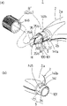
Figure 10 is a stereogram of explaining the operating process of rotating part, the situation that Figure 10 (a) expression is installed on lid the shell cylindrical front end or covers from its dismounting, the situation during Figure 10 (b) expression rotatable cover;
Figure 11 is a stereogram of explaining the erase tool using method, and Figure 11 (a) represents vertical pulling situation, and Figure 11 (b) represents horizontal pulling situation;
Figure 12 also is a stereogram of explaining the erase tool using method, and Figure 12 (a) represents vertical promotion situation, and Figure 12 (b) represents horizontal promotion situation;
Figure 13 is the exploded perspective view of the erase tool of the embodiment of the invention 2;
Figure 14 is the stereogram of the rotating part structure of expression erase tool, the cylindrical front end of film transfer head and shell when Figure 14 (a) expression lid installs, Figure 14 (b) expression cylindrical front end part;
Figure 15 is the enlarged side view of expression rotating part, partly cut-away;
Figure 16 is the exploded perspective view according to the structure of the rotating part of the erase tool of the embodiment of the invention 3, is in the state that covers when installing;
Figure 17 is the enlarged side view of expression rotating part structure, partly cut-away;
Figure 18 is the exploded perspective view of expression according to the rotating part structure of the erase tool of the embodiment of the invention 5, is in the state that lid installs;
Figure 19 is the enlarged side view of expression rotating part structure, partly cut-away;
Figure 20 is the front view according to the erase tool of the embodiment of the invention 6;
Figure 21 is the stereogram of expression erase tool operating position, and Figure 21 (a) and 21 (b) are illustrated in the mode that diverse location grips shell;
Figure 22 is the stereogram that is equivalent to Fig. 6, the improvement example of expression band driven unit, and Figure 22 (a) expression first improves example, and Figure 22 (b) expression second improves example.
Figure 23 is the front view of the common erase tool internal structure of expression, and part is removed;
Figure 24 also is the front view of the common erase tool internal structure of expression, and part is removed.
Consult accompanying drawing now embodiments of the invention are described in detail in detail.
Fig. 1 to 22 expression is according to coating film transfer tool of the present invention, and label identical among the figure is represented components identical.
Be shown in Fig. 1 to 5 according to a kind of coating film transfer tool of the present invention, this coating film transfer tool 1 is the erase tool that error correcting letter etc. is made in special use, supplies with the interchangeable boxlike or the formula that refills as a kind of transition zone T that films of expendable part.
As shown in Figure 1, in coating film transfer tool 1, be to hold and be provided with tape drum C in the shell 2, band transmission component D, the transfer head of filming H and rotating part R.In this erase tool 1, a H can be at vertical pull operation home position (also be film transition zone change position) * (Fig. 2) and between the horizontal pull operation home position Y adjust angle around its axle center.Each constituent part is described below.
I shell 2
As shown in the figure, shell 2 is flat box bodys, and the contour shape that is had, size and width are suitable for holding tape drum C and band transmission component D.Hereinafter will tell about the flat forward and backward surperficial 2a of shell 2, the manual gripping surface that holds and handle of 2b.
When assembling shell 2, the lock pawl 4b of lid 4 is engaged with the bonding part 3b of main body 3, then, make semi-cylindrical shaped part 3c, 4c mutually combines, and assembling rib 4a is assemblied among the recess 3a.At last, will cover 40 and be fitted into bound fraction (cylindrical front end) 5.
II tape drum C
Tape drum C comprises that one is wound with the unwinding shaft 6 of the transition zone T that films, and collection is with the wireline reel 7 of the transition zone T ' that films that crosses.Be connected in the belt driver D of main body 3 tape drum C detachable.Before connection, tape drum C keeps tape drum C by the fixture that is used for fixing axle 6,7.
For example, the transition zone T that films can have following structure.The concrete structure though do not draw, the transition zone T that films has a release agent layer, vinyl chloride-vinyl acids ester copolymer resin (vinylchloride-vinyl acetate copolymer resin) and the low molecular polyethylene layer that on the one side of (approximately 25-38 μ m) plastic foil base, forms for example, above-mentioned plastic foil base can be polyester film, acetate membrane or paper.White is altered enamelled coating and is formed on above-mentioned abscission layer, also is formed with adhesive (contact adhesive) layer on the correction enamelled coating, as pressure-sensitive polyurethane.As altering enamelled coating, use a kind of so-called dry type lacquer that after transfer, can write immediately in the correction district.
Open around axle 6 and wireline reel 7 and have the drum-shaped piece 6a of transition zone T of filming that reels, 7a respectively thereon.At drum-shaped piece 6a, the both sides of 7a are provided with conduction band flange 6b, and 7b is at drum-shaped piece 6a, and the diameter center of 7a is provided with installing hole 6c, and 7c, installing hole have profile of tooth bonding part such as serration and spline.
III band transmission component D
In main body 3, be provided with band transmission component D.Band transmission component D mainly comprises the rotation uncoiling part 10 that is used to rotate and drive out around axle 6, is used to rotate and drive the rotation winding part 11 of wireline reel 7, and the interlocking portions 12 that is used to make above-mentioned two parts 10,11 interlockings.
Rotation is opened around part 10 and is rotated the rotating shaft part 15,16 that winding part 11 comprises hollow respectively, and integrally formed rotating disc 17,18. Rotating shaft part 15,16 is rotatably supported on the periphery that erectly is located at the hollow support shaft 19,20 in the main body 3.Be provided with stopping part 70 in the upper end of hollow support shaft 19,20, shown in Fig. 7 (a).
Corresponding to the installing hole 6c that opens around axle 6 and wireline reel 7,7c, profile of tooth bonding part 71 is separately positioned on the periphery of rotating shaft part 15,16 as serration and spline, shown in Fig. 7 (a).Be engaged in out installing hole 6c around axle 6 and wireline reel 7 profile of tooth bonding part 70,71 detachables, 7c, thereby open around axle 6 and wireline reel 7 detachables be connected in rotating shaft part 15,16 so that unitary rotation.
In this case, rotating disk 17,18 matches with it as the area supported of opening around axle 6 and wireline reel 7, and a pair of pilot pin 21,22 erectly is being arranged in the main body 3 near the installation site of axle 6,7. Pilot pin 21,22 is the transition zone T guiding of filming.
Interlocking portions 12 is used to rotate winding part 11 and rotates the interlocking of opening around part 10, and it comprises rotating disk 17,18 and carriage 25, as shown in Figure 6.
The carriage 25 actual O shape rings that comprise a friction member such as silicon rubber are used for transmitting rotation between rotating part 10,11, and also having an effect is to make out filming in axle 6 and wireline reel 7 change opening around keeping synchronous with winding speed of band T.
Consider at the winding diameter of opening the transition zone T that films in axle 6 and wireline reel 7, initiatively and the rotating ratio between the rotating disk 17,18 of passive side or external diameter than suitably setting, make film transition zone T can successfully open around and coiling.In the illustrated embodiment, be set at rotating disk 17 only about half of in master end at the diameter of the rotating disk 18 of passive side.
Therefore, compressed action (hereinafter will describe in detail) by the transfer head H that films, when (the arrow A direction) tension force on acting on the transition zone T that films acts on out on axle 6 as driving torque, open around axle 6 and with it and on this turns to, be rotated for rotating disk 17 that whole rotation is opened around part 10.By the frictional force of friction member 25, torque is rotated the rotating disk 18 of the rotation winding part 11 of passive side, therefore; On this turns to, rotate, twine automatically around wireline reel 7 with the transition zone T ' that films that crosses with the wireline reel 7 of rotating disk 18 for integral body.
In this case, rotating ratio between the rotating disk 17 and 18 of active and passive side (corresponding to the external diameter ratio) all is constant at any time, and, be inconstant around the transition zone T and be time dependent of filming that opens around axle 6 around the external diameter ratio of filming between the transition zone T ' of wireline reel 7.In other words,, reduce gradually, and all increase gradually around the external diameter of the transition zone T ' that films of wireline reel 7 around the external diameter of opening around the transition zone T that films of axle 6 along with the use of band.
Therefore, compare with opening around opening around speed of axle 6, the winding speed of wireline reel 7 increases in time, and the torque that acts on out on axle 6 increases gradually, and this is mutual nonsynchronous cause because speed becomes.Then,, slide, open around speed and winding speed and be synchronized at the rotating disk 17 of main body side rotating disk 18 with respect to passive side because torque has overcome the frictional force of friction member 25, thus the smooth transmission of the transition zone T that guaranteed to film.
Carry one in passing,, so,, band T is elongated because the transition zone T that films bears excessive tension force if speed keeps above-mentioned asynchronous regime, in addition in separated.
In addition, as shown in Figure 7, rotate winding part 11 and be provided with detent mechanism 30, be used to prevent out backward rotation around axle 6 and wireline reel 7.Detent mechanism 30 comprises the lock pawl 30a that is placed in the rotating disk 18 and is located at the inner surface of main body 3, with the compound ratchet 30b of the form of the concentric ring of hollow support shaft 20,30b ...Lock pawl 30 is sheet form, direction down, vertical towards rotating disk 18, elastically deformable.The cross section of ratchet 30b is wedge shape, is inclined upwardly in the normal direction (shown in the arrow) of wireline reel 7, from the vertical substantially whereabouts of its sharp cutting edge of a knife or a sword.
Therefore, when opening when the wireline reel 7 of axle 6 rotates with the direction of arrow, lock pawl 30a strain, and at ratchet 30b, 30b ... last leap is so that normal rotation.In contrast, when opening around axle 6 and wireline reel 7 when rotating lock pawl 30a engagement pawl 30b, 30b with the opposite direction of arrow ... one of,, thereby prevented backward rotation.Open in rotation and in part 10, can adopt this detent mechanism 30.
The IV transfer head H that films
The transfer head of filming H is used for that the transition zone T that films is pressed to a surface and goes up vicious correction district, and the transfer head of filming H is connected in the inner peripheral surface of cylindrical front end 5 of shell 2 so that rotate around axis.
The transfer head of filming H makes with some flexible plastics, and it comprises the body 35 and the supporting part 36 that is fixed in the cylindrical front end 5 that are used to guide and oppress the transition zone T that films.
Supporting part 36 has an arcuate section at an upper portion thereof and forms half round post, and as shown in Figure 8, its external diameter is corresponding to the semi-cylindrical shaped part 3c of shell 2, the internal diameter of 4c.In addition, the bottom of supporting part 36 forms an arcuate flanges 36a, is used for the axial location of a H, and at semi-cylindrical shaped part 3c, the interior basic circle of 4c correspondingly forms an arc engaging groove 37 respectively in week.
In the above described manner, supporting part 36 axially is rotatably supported in semi-cylindrical shaped part 3c, in the interior week of 4c, arcuate flanges 36a engages with arc engaging groove 37,37 rotationally, therefore, a H axial location in the cylindrical front end 5 of shell 2, but and its axis install rotationally.
V rotating part R
Rotating part R is located in the cylindrical front end 5 of shell 2, is used for rotary head H, and it is connected in the lid 40 of cylindrical front end 5 and the localization part 41 on periphery that is placed on cylindrical front end 5 with comprising a detachable.
Bonding part 43 is provided with the through hole 44 that is used to admit a H.The dimensional structure of through hole 44 makes when H inserts that lid 40 is bonded with each other whole with a H in rotation direction right overhead.In other words, shown in the front view of Fig. 8, through hole 44 comprises that a size makes the few size of the top 44a consistent with the periphery of the body 35 of a H and makes bottom 44b with the periphery unanimity of the supporting 36 of a H.
As Fig. 8 and shown in Figure 9, what localization part 41 was included in figure tubular front end 5 axially goes up the linearly extended guide groove 41a that packs into, and at all upwardly extending limit guide groove 41b of cylindrical front end 5.In this illustrated embodiment, limit guide groove 41b forms in 90 ° of scopes of the central angle of cylindrical front end 5, as shown in Figure 8.In this limit guide groove 41b, equally spaced be provided with a plurality of bonding parts 45 (being 5 bonding part 45a to 45e in the illustrated embodiment).
The connected structure of copulational protuberance 46 and bonding part 45a to 45e is to determine in the following manner.
When the copulational protuberance 46 of lid 40 engaged with the first bonding part 45a, shown in Fig. 2 and 3, a H was in vertical pull operation home position (also being the transition zone replacing position of filming) X.Under this situation, the compressing part 35a of a H front end opens around axle 6 and with identical attitude band T is led during with wireline reel 7 when the transition zone T that films twines, that is, and and the forward and backward surperficial automatic orientation of the transition zone T that films and perpendicular to holding surperficial 2a, 2b.
Then, as shown in Figure 3, be pulled through the compressing part of a H by pilot pin 21 from the transition zone T that films that opens around axle 6 output, and by pilot pin 22 on wireline reel 7, in this process, keep above-mentioned attitude.
On the other hand, (see figure 8) when copulational protuberance 46 engages with the 5th bonding part 45e, as shown in Figure 4 and Figure 5, a H is in horizontal pull operation position Y.In this state, the compressing part 35a of a H guides the transition zone T that films, and makes the roughly positive surperficial 2a that holds in the face of shell 2 in position of band, and 2b that is to say, surperficial 2a, 2b are roughly held in the face of (being parallel to) in the forward and backward surface of band T.
Therefore, reverse 90 ° of angles by pilot pin 21, as shown in Figure 5, then, be pulled through the compressing part 35a in the H front end from the transition zone T ' that films that opens around axle 6 output, by pilot pin 22 with the original state do not turned round on wireline reel 7.
That is to say that by rotatable cover 40, a H can and laterally divide 5 grades and adjust angle at vertical pull operation home position X between the pull operation home position Y.
The concrete structure of rotating part R has more than and is limited to illustrated example.For example, localization part 41 also can be arranged among the semi-cylindrical shaped part 3c of main body 3, in this case, in lid 40, corresponding to localization part 41, also can set up new copulational protuberance.
The operation of the erase tool 1 of said structure is described below.
The A operation:
By rotatable cover 40 (seeing Figure 10 (b)), H can optionally be positioned on any one position, angle in the position, five angles between vertical pull operation position X (this moment, copulational protuberance 46 engaged with the first bonding part 45a) and the horizontal pull operation position Y (copulational protuberance 46 engages with the second bonding part 45b at this moment), thereby can use in the following manner.
Use for carrying out so-called vertical pulling, but a H angle adjustment is on vertical pull operation home position X (see figure 2).On the other hand, laterally spur use for carrying out what is called, but a H angle adjustment is on horizontal pull operation home position Y (see figure 4).In addition, depend on that the user holds the mode of writing implement (custom that the individual is special), but a H angle adjustment is on the appropriate location between home position X and the Y.
I) vertical pulling is used:
This is suitable for the sentence such as the Japanese of local correction vertical writing.Shown in Figure 11 (a), the user resembles to hold with finger and holds the surperficial 2a of holding of shell 2 writing implement, and 2b in this case, is placed on the initiating terminal of revising district 50 with the compressing part 35a in the H front end, revises district 50 and is page or leaf and go up and a wrong zone occurs.In this case, make shell 2 vertical promptly downwards (direction of arrow) move, stop when arriving the terminal (lower end) of revising district 50 when the oppression department in the front end divides.
In this operation, the correction enamelled coating (white) on the transition zone T that films in the compressing part 35a of a H separates with counterdie, shifts and covers and revise district 50, thereby wiped mistake, is altering the word that is easy to correcting writing on the enamelled coating.Meanwhile, because a H follows the action direction of power to a certain extent because of himself elastic force, thereby the transition zone T that films is pressed in revising in the district 50 by the compressing part 35a of a H.
Ii) mould uses to pulling:
This is suitable for the sentence that local correction is laterally write, as English.Shown in Figure 11 (b), the user resembles the spy and holds and hold the surperficial 2a of holding of shell 2 writing implement, 2b, the compressing part 35a of a H is placed on the initiating terminal (left end) in modification district 50 with this state, then, on the page laterally promptly to the right (direction of arrow) mobile shell 2 wipe clerical error until its terminal (right-hand member) of arrive revising the district, can write correct letter more then.
Iii) wipe narrow zone
When wiping a narrow zone as small character in the sentence or one when alphabetical, the terminal head of a quilt H that revises the district blocks, and is difficult to see, thereby is difficult to wipe reliably the word that needs are wiped.
In this case, the user can put upside down and use i) or ii) in usage hold shell 2, as Figure 12 (a) or Figure 12 (b) shown in,, so just can only wipe the word that need wipe like clockwork then with reverse (direction of arrow) promotion shell 2.
B. the replacing of tape drum C:
When the whole length of the transition zone T that films is all used, and collect when coming from unwinding shaft 6 by wireline reel 7, should be according to following step with new tape drum replacing tape drum C.
I) H being entered film transition zone to change the position is vertical pull operation home position X, thereby makes the transition zone T that films on the H be parallel to out winding attitude around axle 6 and wireline reel 7, as shown in Figure 3, therefore can be easily with film transition zone T from the beginning H go up the subordinate.
Ii) shell 2 is taken apart.In this operation, at first will cover 40 and leave behind from the cylindrical front end of shell 2, shown in Figure 10 (a), then, make lid 4 towards last, lift semi-cylindrical shaped part 4c so that lid 4 is pulled down from main body 3.
Iii) at first unload the tape drum C (empty opens around axle 6 and the wireline reel 7 that is wound with the transition zone T ' that films that crosses) that uses up, then unworn tape drum C (having opening around axle 6 and wireline reel 7 of the new transition zone T that films) is placed on the band transmission component D, and makes the transition zone T that films by compressing part 35a at a H front end.
In this operation, as shown in Figure 1, the attitude of transition zone T when opening on axle 6 and wireline reel 7 that keep filming, with opening around part 60a of band, 60b is pulled through pilot pin 21,22, and with the fore-end 60c of band, 60d is inserted in from upside on the both sides of body 35 of a H.
By aforesaid operations, shown in 3, make the transition zone T that films reverse at it, and adjust attitudes so that on wireline reel 7 by pilot pin 22 from opening the compressing part 35a that after axle 6 is pulled out, passes through a H by pilot pin 21.
Accidental H also may deviate from from cylindrical front end 5, can carry out consecutive steps and it be installed again.
IV) then, cover shell 2, ressemble.Herein, shell 2 can assemble by following mode, at first make the engaging claw 4b of lid 4 enter bonding station with the bonding part 3b of main body 3, then, make semi-cylindrical shaped part 4c match with the semi-cylindrical shaped part 3c of main body 3 (thereby notch 3a is engaged with fit ribs 4a), to cover 40 insertings on the cylindrical front end 5 of integral body, shown in Figure 10 (a).
Present embodiment is shown in Figure 13 to Figure 15, and its H can multistagely adjust with respect to the position, angle of shell 2.
The rotating part R ' of present embodiment comprises the pair of engaging part 100,101 on the cylindrical front end 5 that is arranged on a H and shell 2, and the lid 140 that is used for fixing bonding part 100,101 bonding stations.
The bonding part 100 of H is located in the supporting part 36 that can rotate in cylindrical front end 5.That is to say, integrally be provided with an outside flange 102,, that is, on side, form bonding part 100 in the face of the front end face of cylindrical front end 5 at the trailing flank of outside flange 102 at the front end of supporting part 36.On the other hand, the bonding part 101 of cylindrical front end 5 is arranged on its front end face.
The triangle convex-concave surface is made in these bonding parts 100,101, on the inclined-plane that upwards is shaped on staggered inclination the week on two surfaces, shown in Figure 14 (a) and 14 (b).The convex-concave surface of bonding part 100,101 made progress in week, promptly was meshing with each other on rotation direction, thereby had determined a H with respect to cylindrical front end 5, the position, angle that making progress in week.
That is to say, can suitably adjust the bonding station of bonding part 100 with respect to the bonding part 101 of cylindrical front end 5 by rotary head H.Therefore, H not only can be adjusted at the horizontal pull operation home position Y that vertical pull operation home position shown in Figure 2 (also be film transition zone change the position) X or Fig. 5 show with respect to the position, angle of shell 2, and can do multistage adjustment between above-mentioned two positions.The progression of position, angle adjustment depends on the number of the convex-concave surface of bonding part 100,101.
In addition, shown in Figure 13 and 15, the arcuate flanges 36a relevant for the bottom of supporting part 36 in cylindrical front end 5, that is, at two semi-cylindrical shaped part 3c, is shaped on stopping step 137 respectively on week in the bottom of 4c.When arcuate flanges 36 fits into these stopping steps 137,137 o'clock, can prevent that the H from skidding off.
Set to make on its periphery that can be placed on cylindrical front end 5 when covering 140 internal diameter and also can rotate thereon, on the periphery of lid 140, have multiple tooth grip rib.Front end at lid 140 has an inside flange 105, and flange 105 engages with the outside flange 102 of the transfer head H that films.Be shaped on jack 144 from the inner edge to inward flange 105, be common to and pass a H, its shape and size are the circle corresponding to that part of shape of the body 35 of a H.
On the periphery of cylindrical front end 5, or rather, on the periphery of the semi-cylindrical shaped part 4c of lid 4, be provided with and be used to engage and the standing part 141 of fixed cap 140.The same with the localization part 41 of the Figure 13 and first embodiment shown in Figure 14, standing part 141 is included in the axial linearly extended insertion guide groove 141a of going up of cylindrical front end 5, and from inserting all upwardly extending limit guide groove 141b of one of guide groove 141a end in cylindrical front end 5.
As shown in figure 15, when setting the shaping position that limits guide groove 141a, should make cover 140 to inward flange 105 outward flange 102 of a H is pressed to axial inboard, tightly be engaged in the bonding part 101 of cylindrical front end 5 until bonding part 100, be in the state that the copulational protuberance 145 that covers 140 (Figure 14 (a)) engages with limit guide groove 141b.
Terminal at limit guide groove 141b is provided with bonding part 145 (Figure 14 (b)).Bonding part 145 is to be deeper than guide groove 141a, and the hemispherical recess of 141b is arranged on the hemispherical copulational protuberance 146 that covers on interior week of 140 and flexibly is bonded in the bonding part 145 detachable.The shape and size of bonding part 145 and copulational protuberance 146 should be identical with the situation of bonding part 45 among first embodiment and copulational protuberance 46 when setting.
When using the erase tool 1 of said structure, at first want suitable rotary head H to adjust the bonding station of bonding part 100,101, a H is positioned on the position, angle that needs.Then, will cover and 140 externally be fixed on the cylindrical front end 5 (make cover 140 copulational protuberance 145 flexibly be engaged in the bonding part 145 that limits guide groove 141b).Therefore, the bonding part of a H just engages and is fixed in the cylindrical front end 5 of shell 2, and a H is located and is fixed on the position, needed angle.
In the present embodiment, because two bonding parts 100,101 all form around whole circumference, position, the angle adjusting range of the transfer head of filming H 90 ° in first embodiment (though but in fact be subject to the windup-degree of the transition zone of filming, theoretic scope is 360 °).Therefore, not only at Figure 11 (a), (b) the vertical pulling shown in is used or is laterally spurred in the use, and at Figure 12 (a), (b) during the vertical pulling shown in is used or laterally pulling is used, be inverted the user can resemble in embodiment 1 and hold erase tool 1 and need not rotation case 2.Other structure is identical with embodiment 1 with action.
As shown in figure 16, cylindrical front end 5 is integrally formed, is provided with pin thread 241 on its periphery.And on the interior week of lid 140, be provided with negative thread 246, be used for and pin thread 241 engagements.
Therefore, by the bonding station of adjusting bonding part 100,101 H transferred to the position, angle that needs after, to cover 140 is spun on and is fixed on the cylindrical front end 5, two bonding parts 100,101 are bonded with each other and fixing, such H just is positioned and is fixed on the position, angle that needs.Other structure is all identical with embodiment 2 with action.
Present embodiment does not illustrate in the drawings, in this erase tool 1, forms the bonding part 100,101 among embodiment 2 or the embodiment 3 on opposed facing plane, and a H is stepless adjustable with respect to the position, angle of shell 2.Other structure is identical with embodiment 2 or 3 with action.
Be installed in 40 effects that have as the mount spare of shell 2 of lid on the cylindrical front end 5 of shell 2 detachable.Patchhole 144 as embodiment 2 or 3 is provided with patchhole 344 on the assembled portion 43 of lid 40, a H can insert wherein, and head H is rotating circle.Be located at localization part 41 on the periphery of cylindrical front end 5 and engage and be fixed in and cover 40, thereby omitted the bonding part 45a to 45e of the limit guide groove 41b among the embodiment 1.
When using the erase tool 1 of this spline structure, the user resembles to hold and holds the surperficial 2a of holding of shell 2 writing implement, 2b, make the compressing part 35a of a H approach the initiating terminal in the modification district 50 on the page so that revise incorrect letter etc., as Figure 11 or shown in Figure 12, and mobile shell 2 makes compressing part 35a shift to the clearing end of revising district 50.
At this moment, the action direction of a H following force also freely rotates around its axle center, and its position, angle is suitably adjusted.Therefore, by the compressing part 35a of a H, the transition zone T that films always is pressed on and revises in the district 50, wipes wrong letter etc. reliably.Can make in the structure that the action direction of H following force freely rotates this, not only can alter straight line portion such as word is listed as, and can alter sweep such as curve map.
In this erase tool 1, the setting of the shape and size of shell 2 has improved the peculiar function of embodiment 5, that is to say the function that also can alter sweep such as curve map except that altering straight line portion such as word row.
Compare with aforementioned each embodiment, shell 2 has thinner profile, as shown in figure 20.Therefore, the user can resemble and hold pencil or other and hold and use this erase tool 1 writing implement preferably, has a kind of sensation that is better than the writing implement formula of previous embodiment.Relevant therewith, the tape drum C and the band transmission component D that are contained in the shell 2 have also dwindled size.
In the erase tool 1 of this structure, depend on that each user holds the mode of writing implement, can adopt the method for holding shown in Figure 21 (a) or Figure 21 (b).In addition, according to this erase tool 1, for example, as shown in the figure, can alter sweep such as curve map reliably along curve.Other structure is identical with embodiment 5 with action.
In previous embodiment 1-6, for example, adopt the structure that on the release agent layer on the side of base film material, the forms adhesive phase transition zone T that is used as filming, also can be used as a kind of bond tool, only adhesive phase is transferred on the page.
As interlocking portions 12, can adopt the structure shown in Figure 22 (a) or Figure 22 (b) with the structure shown in the alternate figures 6.
Interlocking portions 12 shown in Figure 22 (a) comprises that formation is rotated winding part 11 and rotated the rotating disk of opening around the part of part 10 17,18 respectively, and a friction pulley 75.Specifically, in friction pulley 75, its periphery is made of friction material such as silicon rubber at least.Friction pulley 75 is located at the inboard of housing main body 3 between two rotating disks 17,18, its periphery engages with the periphery of rotating disk 17,18 respectively.
On the other hand, the interlocking portions 12 shown in Figure 22 (b) comprises rotating disk 17, is arranged on the rotation transmitting portions 80 of the downside of rotating disk 18 with one heart, and endless-belt 85.Specifically, endless-belt is made by flexible plastic such as silicon rubber, around rotating disk 17 and rotate on the transmitting portions 80 and with its periphery CONTACT WITH FRICTION.
In addition, all have the transfer function of rotation and slip effect in the structure of the interlocking portions 12 in all illustrated example, but these two kinds of effects can provide individually and independently, see day utility model of the present disclosure for details 5-13800 number and day patent of the present disclosure 5-58097 number.
What so far Shuo Ming all embodiment related to all is automatic auto reeling type, wherein, wireline reel 7 with open around axle 6 interoperations, but the boxlike or refill of the present invention except that illustrated embodiment in also is applicable to there is not the film disposable type of structure of transition zone T of replacing the formula.
According to the present invention, as mentioned above, because the transfer head of filming that transition zone is pressed on the transition range of will filming is adjustable around the position, angle of its axis, thereby the user can be according to the film position, angle of transfer head of practical application or the mode adjustment of oneself holding writing implement.Therefore, no matter whether the user has the personal habits of the uniqueness of holding writing implement, no matter be that vertical pulling is used or laterally pulling is used, all users can both be with a kind of shell of feeling to hold coating film transfer tool of writing implement formula, and the part of the compressing by the transfer head of the filming transition zone of will filming is pressed on the page, thereby fabulous operation convenience is arranged.
In addition because the transfer head of filming can free rotate around its axis, it freely following force action direction and freely rotate, make its position, angle be able to suitable adjustment.Therefore, the transition zone of filming always is pressed on transition range by the oppression department branch of head.But and the action direction of structure following force right overhead and when freely rotating, not only can alter straight line portion reliably such as word is listed as, also can reliably alter crooked part such as curve map.
The present invention may be embodied in other concrete form and does not exceed essence of the present invention and substantive characteristics.Therefore embodiment described in the present disclosure is an illustrative, rather than determinate, can make various modifications and variations and not exceed scope of the present invention it.
Claims (18)
1. coating film transfer tool, it comprises:
Operating means, its shape and size are suitable for carrying out hand-held with a hand;
Band open winding apparatus, it is arranged in the described operating means, is used to out around the transition zone of filming so that feed;
The [of band, it is outstanding from the front end of described operating means, is used for the transition zone of filming of opening winding apparatus institute feed of described band is pressed in transition range; And
The gathering-device of band, it is arranged in the described operating means, is used for the transition zone of filming with mistake of the compressing part of the [front end by band is collected,
It is characterized in that: the front end compressing part of the [of band is an angle adjustable around the coaxial heart.
2. coating film transfer tool, it comprises:
One shell, its shape and size are suitable for carrying out hand-held with a hand;
One opens around axle, and it is arranged on rotationally in the described shell and is twining the transition zone of filming on it;
One transfer head of filming, it is outstanding from the front end of described shell, is used for the transition zone of filming is pressed in transition range; And
One wireline reel, it is arranged in the described shell rotationally, is used to collect the transition zone of filming with crossing,
It is characterized in that: the described transfer head of filming can be adjusted angle around its axle center.
3. coating film transfer tool as claimed in claim 2 is characterized in that: described filming shifted folder and can be installed in rotationally on the interior week of described shell front end around its axle center, and a rotating part that is used to rotate the described transfer head of filming is arranged on the front end of described shell.
4. coating film transfer tool as claimed in claim 3 is characterized in that:
Described rotating part comprises a cylindrical front end that is assemblied in described shell so that the lid that rotates around its axis, and be arranged on localization part on the periphery of described cylindrical front end, be used for multistage ground or infinitely determine describedly covering the position on rotation direction and being fixed on the throne;
The described through hole that holds the described transfer head of filming that is covered with; And
The shape and size of described through hole make that when the described transfer head of filming is contained in the described through hole the mutual monoblock type of described lid and the described transfer head of filming engages.
5. coating film transfer tool as claimed in claim 3, it is characterized in that: the angle of the described transfer head of filming is multistage adjustable, described angle adjustment at least can the compressing part that makes described front end with around described open around the angle of the described transition zone of filming of attitude guiding identical on axle and the wireline reel and guide in the mode of almost holding the surface between the angle of the described transition zone of filming with respect to two of described shell carry out.
6. coating film transfer tool as claimed in claim 2 is characterized in that:
The described transfer head of filming comprises a bonding part that can be arranged on rotationally around the axle center on interior week of described shell front end, and this bonding part is engaged in described front end on rotation direction, and
The bonding part of the described transfer head of filming engages also and is fixed in the front end of described shell, and described lid externally assembles and be fixed on the periphery of front end of described shell.
7. coating film transfer tool as claimed in claim 6, it is characterized in that: the angle of the described transfer head of filming is multistage adjustable, described angle adjustment at least can the compressing that makes described front end with around described open around axle and on reeling the angle and guiding in the mode of almost holding the surface between the angle of the described transition zone of filming of the identical described transition zone of filming of attitude guiding with respect to two of described shell carry out.
8. coating film transfer tool as claimed in claim 2, it is characterized in that: the described transfer head of filming can be arranged on interior week of front end of described shell rotationally around the axle center, and free to rotate, described rotation at least can the compressing part that makes described front end with around described open around the angle of the identical described transition zone of filming of attitude guiding on axle and the wireline reel and guide in the mode of almost holding the surface between the angle of the described transition zone of filming with respect to two of described shell carry out.
9. coating film transfer tool as claimed in claim 2 is characterized in that: described shell is flat box-shaped, and its geometry and width dimensions are suitable for accommodating described opening around axle and wireline reel, and its flat before, the rear surface has formed holds the surface.
10. coating film transfer tool as claimed in claim 2 is characterized in that: described shell is elongated box-shaped, has to be suitable for accommodating the described contour shape of opening around axle and wireline reel, size and width.
11. coating film transfer tool as claimed in claim 2 is characterized in that:
One described open around the axle detachable the rotation that is mounted thereon open around a part and a described wireline reel detachable the rotation winding part that is mounted thereon be separately positioned on rotationally in the described shell; And
Above-mentioned two rotating parts interconnect by an interlocking portions, and described rotation winding part is automatic wound form, and it is independent of described rotation and opens around partly being driven.
12. coating film transfer tool as claimed in claim 11 is characterized in that: described interlocking portions also as carriage so that make described the opening of the transition zone of filming in axle and wireline reel of opening around speed and winding speed synchronization.
13. coating film transfer tool as claimed in claim 12, it is characterized in that: described interlocking portions is provided with one and opens around part and rotate the friction member that uses on the periphery of one of winding part in described rotation, and the periphery of described friction member and another rotating part is frictionally engaged.
14. coating film transfer tool as claimed in claim 11 is characterized in that: described interlocking portions is provided with a friction pulley that is placed on rotationally in the described shell, and the periphery of described friction pulley is opened around part and rotated winding part with rotation respectively and is frictionally engaged.
15. coating film transfer tool as claimed in claim 12 is characterized in that: described interlocking portions is provided with an endless-belt, and described endless-belt is pulled through described rotation respectively and opens around part and the periphery of rotating winding part, so that CONTACT WITH FRICTION.
16. coating film transfer tool as claimed in claim 11 is characterized in that also comprising:
One is used to prevent the described stop mechanism of opening around axle and wireline reel counter-rotating,
Described stop mechanism is included in to adopt pawl on the circle of inner surface of described main body and be located to rotate and opens around part or rotate lock pawl on the winding part, and described lock pawl detachable ground engages with described pawl.
17. coating film transfer tool as claimed in claim 2, it is characterized in that: the described transition zone of filming comprises by plastics, the basement membrane that paper or similar material are made, the release agent layer that on described basement membrane one side, forms, the white that forms on the release agent layer is altered enamelled coating, and also has one to press adhesive phase to form on described white correction enamelled coating.
18. coating film transfer tool as claimed in claim 2, it is characterized in that: the described transition zone of filming comprises plastics, the basement membrane that paper or similar material are made, the release agent layer that on the one side of described basement membrane, forms, and the adhesive phase that on described release agent layer, forms.
Applications Claiming Priority (3)
| Application Number | Priority Date | Filing Date | Title |
|---|---|---|---|
| JP339247/93 | 1993-12-03 | ||
| JP5339247A JP2829699B2 (en) | 1993-12-03 | 1993-12-03 | Paint transfer tool |
| JP339247/1993 | 1993-12-03 |
Publications (2)
| Publication Number | Publication Date |
|---|---|
| CN1113188A CN1113188A (en) | 1995-12-13 |
| CN1051284C true CN1051284C (en) | 2000-04-12 |
Family
ID=18325655
Family Applications (1)
| Application Number | Title | Priority Date | Filing Date |
|---|---|---|---|
| CN94112844A Expired - Lifetime CN1051284C (en) | 1993-12-03 | 1994-12-02 | Coating film transfer tool |
Country Status (10)
| Country | Link |
|---|---|
| US (1) | US5556469A (en) |
| EP (1) | EP0656308B1 (en) |
| JP (1) | JP2829699B2 (en) |
| KR (1) | KR100259256B1 (en) |
| CN (1) | CN1051284C (en) |
| AU (1) | AU685857B2 (en) |
| CA (1) | CA2137055C (en) |
| DE (1) | DE69408109T2 (en) |
| HK (1) | HK1006348A1 (en) |
| TW (1) | TW285651B (en) |
Cited By (1)
| Publication number | Priority date | Publication date | Assignee | Title |
|---|---|---|---|---|
| CN100450792C (en) * | 2005-05-26 | 2009-01-14 | 蜻蜓铅笔株式会社 | Coating film transfer tool and cartridge to be used in the tool |
Families Citing this family (49)
| Publication number | Priority date | Publication date | Assignee | Title |
|---|---|---|---|---|
| GB2275042B (en) * | 1993-02-10 | 1995-10-25 | Gillette Co | Correction tape dispenser |
| GB9422905D0 (en) * | 1994-11-14 | 1995-01-04 | Gillette Co | Tape dispensers |
| TW318812B (en) * | 1994-12-12 | 1997-11-01 | Yutoku Gum Kogyo Kk | |
| AU745383B2 (en) * | 1994-12-12 | 2002-03-21 | Seed Rubber Company Ltd | Tape cartridge for coating film transfer tool and coating film transfer tool |
| JP3306464B2 (en) * | 1994-12-26 | 2002-07-24 | ユニオンケミカー株式会社 | Transfer device |
| US6808565B1 (en) | 1995-10-06 | 2004-10-26 | Seed Rubber Co., Ltd. | Clutch mechanism of coat film transfer tool and coat film transfer tool |
| JP3516188B2 (en) * | 1995-10-27 | 2004-04-05 | 株式会社トンボ鉛筆 | Transfer tape transfer and take-up part of applicator |
| US5759270A (en) * | 1996-02-29 | 1998-06-02 | Katsuyuki Miyazaki | Correction tape adhesiver for correcting mistyped letters |
| DE19635586B4 (en) * | 1996-09-02 | 2005-10-20 | Bic Clichy Soc | Handheld device for transferring a film from z. B. adhesive or opaque or colored material from a wound on a supply reel carrier tape on a substrate |
| USD410494S (en) * | 1997-09-26 | 1999-06-01 | Bic Corporation | Correction-tape dispenser |
| USD421461S (en) * | 1997-12-31 | 2000-03-07 | Henkel Kgaa | Holder with correcting tape |
| NL1008130C2 (en) * | 1998-01-27 | 1999-07-28 | Henkel Kgaa | Material transfer device with pivotable transfer member. |
| DE29801395U1 (en) * | 1998-01-30 | 1998-05-28 | Henkel KGaA, 40589 Düsseldorf | Adhesive dispenser |
| JPH11227385A (en) | 1998-02-12 | 1999-08-24 | Fujicopian Co Ltd | Coating film transfer implement |
| JPH11245500A (en) * | 1998-03-03 | 1999-09-14 | Seiji Endo | Foil printer |
| US5942036A (en) * | 1998-05-12 | 1999-08-24 | You; Kwang-Ho | Correction tape roller device |
| CN1106295C (en) * | 1998-06-15 | 2003-04-23 | 柳光洁 | Correction tape |
| US6125903A (en) * | 1998-06-15 | 2000-10-03 | Toyo Chemical Co., Ltd. | Adhesive transfer device |
| DE19830522A1 (en) * | 1998-07-08 | 2000-01-13 | Pritt Produktionsgesellschaft | Device for transferring a substance applied in the form of a film to a carrier tape |
| JP2000025392A (en) * | 1998-07-08 | 2000-01-25 | Seed Rubber Kogyo Kk | Tape cartridge for coating film transfer implement and coating film transfer implement |
| USD433449S (en) * | 1998-10-21 | 2000-11-07 | Plus Kabushiki Kaisha | Correction coat-of-paint applicator for office use |
| USD410955S (en) * | 1998-12-11 | 1999-06-15 | Bic Corporation | Correction-tape dispenser |
| US6352770B1 (en) | 1999-01-15 | 2002-03-05 | Bic Corporation | Correction tape having dye migration blocking properties |
| US6260599B1 (en) | 1999-06-11 | 2001-07-17 | Kwang-Ho You | Correction tape roller device |
| JP2001018587A (en) * | 1999-07-06 | 2001-01-23 | Seed Rubber Kogyo Kk | Coating film transfer head device and coating film transfer tool |
| DE19936445B4 (en) * | 1999-08-03 | 2004-03-04 | SOCIéTé BIC | Handheld device for transferring a film from a carrier tape to a substrate |
| US6739816B1 (en) | 2000-11-24 | 2004-05-25 | Hewlett-Packard Development Company, L.P. | Systems and methods of attaching a cover to a text body |
| US6543511B2 (en) | 2000-12-01 | 2003-04-08 | Volker Niermann | Tape dispenser |
| DE10118830B4 (en) * | 2001-04-17 | 2009-06-18 | Henkel Ag & Co. Kgaa | cassette player |
| JP4603738B2 (en) * | 2001-09-28 | 2010-12-22 | プラス株式会社 | Coating film transfer tool |
| DE10156100A1 (en) * | 2001-11-16 | 2003-06-05 | Citius Gmbh Buerotechnik | Applicator head for spooled film placement limits head rotation by guides and endstops and uses shafted tongue and pressdown for self-aligning film placement. |
| JP4142871B2 (en) * | 2001-12-27 | 2008-09-03 | 株式会社シード | Mark transfer tool, mark transfer tape, and method of manufacturing mark transfer tape |
| US20050056375A1 (en) * | 2003-09-16 | 2005-03-17 | Sanford, L.P. | Applicator tip for a corrective tape dispenser |
| US6997229B2 (en) * | 2003-09-16 | 2006-02-14 | Sanford, L.P. | Rotatable applicator tip for a corrective tape dispenser |
| DE102006027495B4 (en) * | 2006-06-14 | 2008-04-24 | Henkel Kgaa | Apparatus for transferring a film from a carrier tape to a substrate |
| DE102006031173B4 (en) * | 2006-07-06 | 2011-04-14 | Henkel Ag & Co. Kgaa | Apparatus for transferring a film from a carrier tape to a substrate |
| KR101109573B1 (en) * | 2007-08-20 | 2012-01-31 | 홍성만 | Discharge guide system of cut-tape for automatic tape cutter |
| JP4899103B2 (en) * | 2007-09-28 | 2012-03-21 | コクヨ株式会社 | Transfer device |
| KR200449531Y1 (en) * | 2008-05-27 | 2010-07-16 | (주)세줄 | Glue tape dispenser with anti-torsion cartrdige |
| KR200450069Y1 (en) * | 2010-03-29 | 2010-09-03 | 인성테크 주식회사 | Transfer tape dispenser having device for preventing reverse |
| US8657170B2 (en) * | 2010-05-24 | 2014-02-25 | Lynda Martinez | False eyelash dispenser |
| US8397784B2 (en) | 2010-08-31 | 2013-03-19 | Sanford, L.P. | Correction tape dispenser with variable clutch mechanism |
| US8578999B2 (en) | 2010-12-29 | 2013-11-12 | Sanford, L.P. | Variable clutch mechanism and correction tape dispenser with variable clutch mechanism |
| US8746313B2 (en) | 2010-12-29 | 2014-06-10 | Sanford, L.P. | Correction tape re-tensioning mechanism and correction tape dispenser comprising same |
| US8746316B2 (en) | 2011-12-30 | 2014-06-10 | Sanford, L.P. | Variable clutch mechanism and correction tape dispenser with variable clutch mechanism |
| CN104270997B (en) | 2013-03-01 | 2018-03-02 | 松下知识产权经营株式会社 | Transfer device and printing equipment |
| JP6164458B2 (en) * | 2013-03-28 | 2017-07-19 | フジコピアン株式会社 | Film transfer tool |
| JP6273485B2 (en) * | 2013-05-20 | 2018-02-07 | フジコピアン株式会社 | Film transfer tool |
| CN110435343B (en) * | 2019-08-02 | 2024-05-31 | 中国地质大学(武汉) | Correction tape structure capable of adjusting tightness of belt wheel |
Citations (2)
| Publication number | Priority date | Publication date | Assignee | Title |
|---|---|---|---|---|
| US4826562A (en) * | 1987-05-28 | 1989-05-02 | Doro Tape Ehlis Kg | Device for unwinding transfer tape from a roll |
| EP0556406A1 (en) * | 1991-08-30 | 1993-08-25 | Seed Rubber Company Ltd. | Coating film transfer device |
Family Cites Families (13)
| Publication number | Priority date | Publication date | Assignee | Title |
|---|---|---|---|---|
| US4547088A (en) * | 1980-06-26 | 1985-10-15 | International Business Machines Corporation | Correctable thermal transfer printing ribbon |
| CH645851A5 (en) * | 1980-09-09 | 1984-10-31 | Buettner Ag Franz | RIBBON FOR GENERATING CORRECTABLE CHARACTERS. |
| US4521471A (en) * | 1982-09-15 | 1985-06-04 | General Electric Company | Processes and articles for removing typewriter inks |
| DK165628C (en) * | 1984-03-09 | 1993-05-24 | Fuji Kagaku Shikogyo | RURAL TAPE FOR MULTIPLE USE |
| JPS6157370A (en) * | 1984-07-31 | 1986-03-24 | Shigeru Tamai | Correcting implement for character or the like |
| US4718971A (en) * | 1986-10-09 | 1988-01-12 | Moore Push-Pin Company | Dispenser for a transfer adhesive |
| DE3900156A1 (en) * | 1989-01-04 | 1990-07-05 | Czewo Plast Kunststofftech | DEVICE FOR APPLYING AN ADHESIVE FILM |
| DE3907753C1 (en) * | 1989-03-10 | 1990-09-06 | Pelikan Ag, 3000 Hannover, De | |
| JPH0311639A (en) * | 1989-06-08 | 1991-01-18 | Fujitsu Ltd | Manufacture of semiconductor device |
| JPH0513800A (en) * | 1991-07-05 | 1993-01-22 | Sharp Corp | Semiconductor device |
| DE4220843C1 (en) * | 1992-06-25 | 1993-08-05 | Citius Buerotechnik Gmbh, 8906 Gersthofen, De | |
| US5310445A (en) * | 1992-10-15 | 1994-05-10 | The Gillette Company | Tape dispenser |
| JP2807805B2 (en) * | 1993-09-22 | 1998-10-08 | シードゴム工業株式会社 | Paint transfer tool |
-
1993
- 1993-12-03 JP JP5339247A patent/JP2829699B2/en not_active Expired - Lifetime
-
1994
- 1994-11-23 US US08/346,241 patent/US5556469A/en not_active Expired - Lifetime
- 1994-11-24 DE DE69408109T patent/DE69408109T2/en not_active Expired - Lifetime
- 1994-11-24 EP EP94308688A patent/EP0656308B1/en not_active Expired - Lifetime
- 1994-11-26 TW TW083111023A patent/TW285651B/zh not_active IP Right Cessation
- 1994-11-30 AU AU79118/94A patent/AU685857B2/en not_active Expired
- 1994-11-30 CA CA002137055A patent/CA2137055C/en not_active Expired - Lifetime
- 1994-12-02 CN CN94112844A patent/CN1051284C/en not_active Expired - Lifetime
- 1994-12-03 KR KR1019940032755A patent/KR100259256B1/en not_active IP Right Cessation
-
1998
- 1998-06-17 HK HK98105515A patent/HK1006348A1/en unknown
Patent Citations (2)
| Publication number | Priority date | Publication date | Assignee | Title |
|---|---|---|---|---|
| US4826562A (en) * | 1987-05-28 | 1989-05-02 | Doro Tape Ehlis Kg | Device for unwinding transfer tape from a roll |
| EP0556406A1 (en) * | 1991-08-30 | 1993-08-25 | Seed Rubber Company Ltd. | Coating film transfer device |
Cited By (1)
| Publication number | Priority date | Publication date | Assignee | Title |
|---|---|---|---|---|
| CN100450792C (en) * | 2005-05-26 | 2009-01-14 | 蜻蜓铅笔株式会社 | Coating film transfer tool and cartridge to be used in the tool |
Also Published As
| Publication number | Publication date |
|---|---|
| DE69408109D1 (en) | 1998-02-26 |
| DE69408109T2 (en) | 1998-06-10 |
| AU7911894A (en) | 1995-06-08 |
| CN1113188A (en) | 1995-12-13 |
| CA2137055C (en) | 2005-04-26 |
| EP0656308B1 (en) | 1998-01-21 |
| CA2137055A1 (en) | 1995-06-04 |
| KR100259256B1 (en) | 2000-10-02 |
| AU685857B2 (en) | 1998-01-29 |
| HK1006348A1 (en) | 1999-02-19 |
| JP2829699B2 (en) | 1998-11-25 |
| TW285651B (en) | 1996-09-11 |
| JPH07157175A (en) | 1995-06-20 |
| EP0656308A1 (en) | 1995-06-07 |
| US5556469A (en) | 1996-09-17 |
| KR950017200A (en) | 1995-07-20 |
Similar Documents
| Publication | Publication Date | Title |
|---|---|---|
| CN1051284C (en) | Coating film transfer tool | |
| CN1107635C (en) | Coating film transfer tool | |
| CN1125731C (en) | Clutch mechanism of cover film transfer tool and cover film transfer tool | |
| JP2943134B2 (en) | Tape cartridge for paint film transfer tool and paint film transfer tool | |
| JP2876301B2 (en) | Clutch mechanism of coating film transfer device and coating film transfer device | |
| CN1154581C (en) | Clutch mechanism of coating film transmission device and coating film transmission device | |
| JP2000025392A (en) | Tape cartridge for coating film transfer implement and coating film transfer implement | |
| US8578999B2 (en) | Variable clutch mechanism and correction tape dispenser with variable clutch mechanism | |
| AU711604B2 (en) | Tape cartridge for coating film transfer tool and coating film transfer tool | |
| KR20000005998A (en) | Tape cartridge for coat film transfer tool and coat film transfer tool | |
| US8746316B2 (en) | Variable clutch mechanism and correction tape dispenser with variable clutch mechanism | |
| CN1903587A (en) | Sticking tool | |
| US20110198037A1 (en) | Coating Film Transfer Tool | |
| CN211056288U (en) | Laborsaving body paper unwinding device | |
| CN100341760C (en) | Scroll type containing device and method of rolling up and releasing flexible sheetlike material | |
| JP3071759B2 (en) | Paint transfer tool | |
| JP3670092B2 (en) | Supply reel device for modified paint film transfer tape in eraser | |
| JPH11342699A (en) | Coating film transfer implement | |
| JPH09104563A (en) | Tape rewinding mechanism for paint film transfer implement and paint film transfer implement | |
| AU745383B2 (en) | Tape cartridge for coating film transfer tool and coating film transfer tool | |
| AU5658100A (en) | Clutch mechanism of coat film transfer tool and coat film transfer tool | |
| CN1614689A (en) | Magnetic data reading and recording device | |
| CN1741947A (en) | Transfer devices |
Legal Events
| Date | Code | Title | Description |
|---|---|---|---|
| C06 | Publication | ||
| PB01 | Publication | ||
| C10 | Entry into substantive examination | ||
| SE01 | Entry into force of request for substantive examination | ||
| C14 | Grant of patent or utility model | ||
| GR01 | Patent grant | ||
| C17 | Cessation of patent right | ||
| CX01 | Expiry of patent term |
Expiration termination date: 20141202 Granted publication date: 20000412 |