CN1125731C - Clutch mechanism of cover film transfer tool and cover film transfer tool - Google Patents
Clutch mechanism of cover film transfer tool and cover film transfer tool Download PDFInfo
- Publication number
- CN1125731C CN1125731C CN98118371A CN98118371A CN1125731C CN 1125731 C CN1125731 C CN 1125731C CN 98118371 A CN98118371 A CN 98118371A CN 98118371 A CN98118371 A CN 98118371A CN 1125731 C CN1125731 C CN 1125731C
- Authority
- CN
- China
- Prior art keywords
- transition zone
- supporting member
- coverlay
- drive unit
- roll coil
- Prior art date
- Legal status (The legal status is an assumption and is not a legal conclusion. Google has not performed a legal analysis and makes no representation as to the accuracy of the status listed.)
- Expired - Fee Related
Links
- 238000012546 transfer Methods 0.000 title claims abstract description 119
- 230000007246 mechanism Effects 0.000 title claims abstract description 108
- 239000013039 cover film Substances 0.000 title abstract 3
- 230000005540 biological transmission Effects 0.000 claims abstract description 19
- 230000007704 transition Effects 0.000 claims description 100
- 210000000078 claw Anatomy 0.000 claims description 32
- 239000011324 bead Substances 0.000 claims description 23
- 230000000694 effects Effects 0.000 claims description 23
- 230000001360 synchronised effect Effects 0.000 claims description 16
- 230000002040 relaxant effect Effects 0.000 claims 1
- 238000004519 manufacturing process Methods 0.000 abstract description 4
- 238000004804 winding Methods 0.000 abstract description 4
- 238000003825 pressing Methods 0.000 abstract description 2
- 239000010408 film Substances 0.000 abstract 1
- 206010040007 Sense of oppression Diseases 0.000 description 9
- 230000003321 amplification Effects 0.000 description 8
- 238000000576 coating method Methods 0.000 description 8
- 239000010410 layer Substances 0.000 description 8
- 238000003199 nucleic acid amplification method Methods 0.000 description 8
- 239000011248 coating agent Substances 0.000 description 7
- 238000012937 correction Methods 0.000 description 7
- 238000013461 design Methods 0.000 description 7
- 239000000463 material Substances 0.000 description 7
- 125000004122 cyclic group Chemical group 0.000 description 5
- 239000012790 adhesive layer Substances 0.000 description 4
- 238000009434 installation Methods 0.000 description 4
- 238000000034 method Methods 0.000 description 4
- 239000000654 additive Substances 0.000 description 3
- 230000000996 additive effect Effects 0.000 description 3
- 239000004820 Pressure-sensitive adhesive Substances 0.000 description 2
- 230000009471 action Effects 0.000 description 2
- 230000008859 change Effects 0.000 description 2
- 239000003795 chemical substances by application Substances 0.000 description 2
- 238000010586 diagram Methods 0.000 description 2
- 239000000203 mixture Substances 0.000 description 2
- 230000004048 modification Effects 0.000 description 2
- 238000012986 modification Methods 0.000 description 2
- 238000000465 moulding Methods 0.000 description 2
- 239000013589 supplement Substances 0.000 description 2
- 241000219112 Cucumis Species 0.000 description 1
- 235000015510 Cucumis melo subsp melo Nutrition 0.000 description 1
- 241000196324 Embryophyta Species 0.000 description 1
- 239000004698 Polyethylene Substances 0.000 description 1
- 229920002433 Vinyl chloride-vinyl acetate copolymer Polymers 0.000 description 1
- FJJCIZWZNKZHII-UHFFFAOYSA-N [4,6-bis(cyanoamino)-1,3,5-triazin-2-yl]cyanamide Chemical compound N#CNC1=NC(NC#N)=NC(NC#N)=N1 FJJCIZWZNKZHII-UHFFFAOYSA-N 0.000 description 1
- 239000002775 capsule Substances 0.000 description 1
- 239000011247 coating layer Substances 0.000 description 1
- 230000021615 conjugation Effects 0.000 description 1
- 230000008878 coupling Effects 0.000 description 1
- 238000010168 coupling process Methods 0.000 description 1
- 238000005859 coupling reaction Methods 0.000 description 1
- 238000001514 detection method Methods 0.000 description 1
- 230000008034 disappearance Effects 0.000 description 1
- 230000005489 elastic deformation Effects 0.000 description 1
- 238000005516 engineering process Methods 0.000 description 1
- 150000002168 ethanoic acid esters Chemical class 0.000 description 1
- 229920002457 flexible plastic Polymers 0.000 description 1
- 230000006872 improvement Effects 0.000 description 1
- 238000001746 injection moulding Methods 0.000 description 1
- 238000003780 insertion Methods 0.000 description 1
- 230000037431 insertion Effects 0.000 description 1
- 238000007689 inspection Methods 0.000 description 1
- 230000002093 peripheral effect Effects 0.000 description 1
- 229920003023 plastic Polymers 0.000 description 1
- 239000004033 plastic Substances 0.000 description 1
- 229920000728 polyester Polymers 0.000 description 1
- -1 polyethylene Polymers 0.000 description 1
- 229920000573 polyethylene Polymers 0.000 description 1
- 229920002635 polyurethane Polymers 0.000 description 1
- 239000004814 polyurethane Substances 0.000 description 1
- 230000008569 process Effects 0.000 description 1
- 230000001105 regulatory effect Effects 0.000 description 1
- 230000003252 repetitive effect Effects 0.000 description 1
- 229920005989 resin Polymers 0.000 description 1
- 239000011347 resin Substances 0.000 description 1
- 238000007665 sagging Methods 0.000 description 1
Images


Classifications
-
- B—PERFORMING OPERATIONS; TRANSPORTING
- B43—WRITING OR DRAWING IMPLEMENTS; BUREAU ACCESSORIES
- B43L—ARTICLES FOR WRITING OR DRAWING UPON; WRITING OR DRAWING AIDS; ACCESSORIES FOR WRITING OR DRAWING
- B43L19/00—Erasers, rubbers, or erasing devices; Holders therefor
-
- B—PERFORMING OPERATIONS; TRANSPORTING
- B65—CONVEYING; PACKING; STORING; HANDLING THIN OR FILAMENTARY MATERIAL
- B65H—HANDLING THIN OR FILAMENTARY MATERIAL, e.g. SHEETS, WEBS, CABLES
- B65H37/00—Article or web delivery apparatus incorporating devices for performing specified auxiliary operations
- B65H37/002—Web delivery apparatus, the web serving as support for articles, material or another web
- B65H37/005—Hand-held apparatus
- B65H37/007—Applicators for applying coatings, e.g. correction, colour or adhesive coatings
-
- B—PERFORMING OPERATIONS; TRANSPORTING
- B65—CONVEYING; PACKING; STORING; HANDLING THIN OR FILAMENTARY MATERIAL
- B65H—HANDLING THIN OR FILAMENTARY MATERIAL, e.g. SHEETS, WEBS, CABLES
- B65H2402/00—Constructional details of the handling apparatus
- B65H2402/60—Coupling, adapter or locking means
-
- Y—GENERAL TAGGING OF NEW TECHNOLOGICAL DEVELOPMENTS; GENERAL TAGGING OF CROSS-SECTIONAL TECHNOLOGIES SPANNING OVER SEVERAL SECTIONS OF THE IPC; TECHNICAL SUBJECTS COVERED BY FORMER USPC CROSS-REFERENCE ART COLLECTIONS [XRACs] AND DIGESTS
- Y10—TECHNICAL SUBJECTS COVERED BY FORMER USPC
- Y10T—TECHNICAL SUBJECTS COVERED BY FORMER US CLASSIFICATION
- Y10T156/00—Adhesive bonding and miscellaneous chemical manufacture
- Y10T156/17—Surface bonding means and/or assemblymeans with work feeding or handling means
- Y10T156/1702—For plural parts or plural areas of single part
- Y10T156/1705—Lamina transferred to base from adhered flexible web or sheet type carrier
-
- Y—GENERAL TAGGING OF NEW TECHNOLOGICAL DEVELOPMENTS; GENERAL TAGGING OF CROSS-SECTIONAL TECHNOLOGIES SPANNING OVER SEVERAL SECTIONS OF THE IPC; TECHNICAL SUBJECTS COVERED BY FORMER USPC CROSS-REFERENCE ART COLLECTIONS [XRACs] AND DIGESTS
- Y10—TECHNICAL SUBJECTS COVERED BY FORMER USPC
- Y10T—TECHNICAL SUBJECTS COVERED BY FORMER US CLASSIFICATION
- Y10T156/00—Adhesive bonding and miscellaneous chemical manufacture
- Y10T156/17—Surface bonding means and/or assemblymeans with work feeding or handling means
- Y10T156/1788—Work traversing type and/or means applying work to wall or static structure
- Y10T156/1795—Implement carried web supply
-
- Y—GENERAL TAGGING OF NEW TECHNOLOGICAL DEVELOPMENTS; GENERAL TAGGING OF CROSS-SECTIONAL TECHNOLOGIES SPANNING OVER SEVERAL SECTIONS OF THE IPC; TECHNICAL SUBJECTS COVERED BY FORMER USPC CROSS-REFERENCE ART COLLECTIONS [XRACs] AND DIGESTS
- Y10—TECHNICAL SUBJECTS COVERED BY FORMER USPC
- Y10T—TECHNICAL SUBJECTS COVERED BY FORMER US CLASSIFICATION
- Y10T156/00—Adhesive bonding and miscellaneous chemical manufacture
- Y10T156/18—Surface bonding means and/or assembly means with handle or handgrip
Landscapes
- Adhesive Tape Dispensing Devices (AREA)
- Storage Of Web-Like Or Filamentary Materials (AREA)
Abstract
A clutch mechanism for a transfer tool for automatically collecting covering films is easy to manufacture, high in assembly precision, simple in structure and low in cost. A transfer tape winding core around which a cover film transfer tape is wound is held and supported from both sides in the axial direction by a dispensing gear and a rewind button. The transfer tape winding core and the dispensing gear are frictionally engaged with each other in the rotational direction by a friction force generated by a thrust load by the power transmission device. The power transmission device is composed of a plurality of engaging projections integrally formed on the dispensing gear, and these engaging projections can be elastically engaged with the axial end of the transfer tape winding core by a predetermined pressing force caused by the axial engaging force of the dispensing gear and the rewinding button.
Description
The present invention relates to a kind of clutch mechanism of coat film transfer tool and have the coat film transfer tool of this clutch mechanism, say that more specifically relating to a kind of Clutch Technology is providing reel and batching the granting speed of the coverlay transition zone in the reel and batch speed synchronous so that be used for making, thereby have in the coat film transfer tool of clutch mechanism one and to utilize this mechanism that correction enamelled coating or adhesive layer that one coverlay for example is coated on the coverlay transition zone are transferred on paper or the analog, and the coverlay transition zone after will using reclaims automatically.
One example of the structure of this coat film transfer tool is shown in Figure 20, wherein transfer tool has a granting reel c who contains a volume coverlay transition zone b, with one be used for reclaiming coverlay transition zone b ' after the use collect reel d, this two reel all can be rotatably set in housing a upward so that grip and operation with a hand, also has a coverlay transfer head f to stretch out from the termination of housing a so that be used for coverlay transition zone b is pressed on the transport zone.This two reel c, d are connected to each other by link gear g, belong to the formula of collecting automatically and collect reel d.Link gear g is for being located at this two reel c, d outside intermeshed gear h, i.When this coat film transfer tool is used as erase tool so that when righting a wrong, an available hand grips housing a, coverlay transition zone b is pressed on the correction zone (transport zone), utilizes the oppression department j on the f when pressing, housing a is moved on the direction of appointment.Correction enamelled coating on the coverlay transition zone b in the result f oppression department j just is applied to and corrects on the zone, thereby covers and wipe word or the analog of being write, and the coverlay transition zone b ' after using can automatically be collected and be recovered to and collects on the reel d.
In this case, through reusing, reduce gradually at the external diameter of providing the coverlay transition zone b on the reel c, and increase gradually at the external diameter of collecting the coverlay transition zone b ' on the reel d.On the other hand, granting reel c is constant all the time with the rotating ratio (gear ratio that is equivalent to link gear g) of collecting reel d.Therefore, the speed of collecting of collecting reel d at last can be greater than the granting speed of providing reel c, and will prevent this point, must make to provide speed and to collect speed synchronous.For this purpose, on granting reel c, be provided with a clutch mechanism k so that provide speed and collect speed synchronous.
Promptly in providing reel c, there is the wheel hub m of a driven wheel to can be rotated to support on the bolster n, also have the granting roll coil of strip core o that coverlay transition zone b is wound thereon rotatably to be fitted on the wheel hub m, and clutch mechanism k is set between wheel hub m and the granting roll coil of strip core o.
This clutch mechanism k comprises clutch claw p, the p of the strain diametrically that is arranged on the wheel hub m periphery, they flexibly and separatably be located at provide many ratchet q, the q on week in the roll coil of strip core o ... engagement.
Become at last when providing speed and cause two speed synchronous destroyed when collecting speed, act on the torque of providing on the roll coil of strip core o and just can become big, clutch mechanism k just can work, and provides roll coil of strip core o and just can slide on wheel hub m, makes granting speed and collect speed synchronous.
This clutch mechanism k clutch claw p, p and ratchet q, q ... between when engagement taking place and throwing off action, since flexible click can repeat off and on to take place, the user is felt under the weather, and the operation meeting of coverlay transition zone b is inhomogeneous, and the consumption of working as transition zone constantly increases, can constantly become big in the difference of providing speed and collect between the speed, cause this engagement and disengagement action more and more frequent, uncomfortable and uneven operation will be more and more significant, therefore requires further improvement.
In this respect, the inventor once proposed a kind of clutch mechanism r in the past, (for example saw that Japan postpones publication 5-58097 number) as shown in figure 21.In this clutch mechanism r, a flexible friction member s is arranged, as o ring, be plugged on the periphery of wheel hub m and provide between the interior week of roll coil of strip core o with the state that is frictionally engaged.
According to this clutch mechanism r, when carrying out synchronous effect, these three m, s, o can relatively slide mutually swimmingly, therefore owing to uncomfortable and uneven operation flexible and that repetitive operation intermittently causes can be eliminated.
But in the structure of this clutch mechanism r, because the transmission of power is to utilize the frictional force that radial load produced that is applied on these three m, s, the o to carry out.Therefore the design condition of friction member s and create conditions very strictly is difficult to make, and is difficult for reducing manufacturing cost.
Also promptly, if frictional force is strong excessively, when using in the second half section so, operation sense will become and require great effort very much.On the other hand, if frictional force excessively a little less than, in the starting stage of using, operation sense will become too weak and feeble so.Therefore frictional force must be considered these relations and be set at optimum value.
In order to obtain the optimum value of frictional force, when designing and creating friction part s, its interior diameter and overall diameter must be respectively with the periphery of wheel hub m with provide interior week coupling of roll coil of strip core o, and, also must consider its gauge that directly makes progress because friction member s itself also is flexible.Therefore, after clutch mechanism r is assembled together, need an operation in addition, be used for the shape and size of friction member s are done accurate adjusting.
And, because the diameter of friction member s set by strictness, friction member s must exert oneself to plant wheel hub m periphery and provide between the interior week of roll coil of strip core o, this makes assembly work have big difficulty.
Therefore primary and foremost purpose of the present invention is that a kind of new clutch mechanism will be provided, and it can eliminate problems of the prior art.
Another object of the present invention is that a kind of clutch mechanism of collecting automatically in the formula coat film transfer tool will be provided, and it has a simply and not expensive structure, makes easily, and can apply frictional force with thrust load, thereby obtain high assembly precision.
Different purpose of the present invention is that a kind of clutch mechanism will be provided, and its member can relatively slide when carrying out synchronous effect mutually smoothly, has good operation sense, does not have uneven operation.
A further object of the invention is that a kind of clutch mechanism will be provided, and the design of its member and create conditions and can relax is made easily, easily assembling.
Another object of the present invention is that a kind of clutch mechanism will be provided, and it can reduce manufacturing expense, can also reduce the expense of whole device.
The present invention also have a various objectives be to provide a kind of cheap, collect the coat film transfer tool of formula automatically, this instrument has this clutch mechanism, simple structure, number of components is few, makes the assembly precision height easily.
Clutch mechanism of the present invention is used in to be collected in the formula coat film transfer tool automatically, the latter has a granting reel that contains a volume coverlay transition zone, with a reel of collecting that is used for reclaiming coverlay transition zone after the use, this two reel all rotatably is contained in the housing so that with a hand gripping and operation, collect reel and provide the reel interlocking; This clutch mechanism is located in two reels at least one, be designed so that the granting speed of coverlay transition zone between two reels and collect speed synchronous, the transfer roll coil of strip core of coverlay transition zone of wherein being used for reeling is held and is bearing in one and is used for rotating and driving this rotary drive unit that shifts roll coil of strip core and one between the joint supporting member that axially engages with rotary drive unit, shifting roll coil of strip core and the frictional force of rotary drive unit utilization on direction of rotation engages one another, this frictional force is to be provided by force transfering device by the frictional force that thrust load causes, this force transfering device has the friction member of a plurality of strains in the axial direction, they are set at rotary drive unit and engage in the supporting member at least one, and these friction members can along shift roll coil of strip core axially with the pressure of regulation flexibly with the end joined that shifts roll coil of strip core, and this pressure is to be provided by rotary drive unit and the axial engagement power that engages supporting member.
Coat film transfer tool of the present invention comprises above-mentioned clutch mechanism, also comprises: a housing, and its shape and size are suitable to grip and operates with a hand; A granting reel that contains a volume coverlay transition zone, it rotatably is located in the housing; The reel of collecting that is used for reclaiming coverlay transition zone after the use, it rotatably is located in the housing; A link gear is used for connecting this two reel so that make their interlockings; And a coverlay transfer head of stretching out from the housing front end, be used for the coverlay transition zone is pressed on the transport zone, and clutch mechanism is located at least one reel in two reels.
Coat film transfer tool with this clutch mechanism can have for the pattern of selling: disposable use type, and when using up, the coverlay transition zone can abandon; Again supplement type uses up new the changing of the available volume in back at the coverlay transition zone.
With regard to coverlay transition zone of the present invention, when surpassing the granting speed of providing reel so that synchronous destroyed between them when collecting the collecting that speed accelerates gradually of reel, the torque that is used for reeling the coverlay transition zone and acts on the transfer roll coil of strip core also is increased, but because the effect of clutch mechanism, mobile roll coil of strip core can slide and rotate facing to rotary drive unit, therefore thereby the torque differences of two reels is eliminated, and provides speed just with to collect speed synchronous.
In this case, because transfer roll coil of strip core and rotary drive unit engage one another with the frictional force of direction of rotation, and this frictional force is to be provided by force transfering device by the frictional force that thrust load causes, and therefore shifts roll coil of strip core and can successfully slide relatively mutually with rotary drive unit.
The frictional engagement force of force transfering device can be set to optimum value, if rotary drive unit and engage supporting member axially on regulate bond sizes suitably and just can set the two axial engagement power.
From the detailed description of doing below in conjunction with the fact of the novelty of pointing out accompanying drawing and the claim, when can to above-mentioned these and other some purposes of the present invention and characteristics are understood preferably and certainly.
Fig. 1 (a) is the front view that the coat film transfer tool of the embodiment of the invention 1 is shown.
Fig. 1 (b) illustrates its inner front view after the lid of coat film transfer tool is taken away.
Fig. 2 is for illustrating the cutaway view that coat film transfer tool cuts along II-II line among Fig. 1 (b).
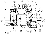
Fig. 3 is the amplification view of clutch mechanism of the formant of coat film transfer tool.
Fig. 4 is the exploded view of the perspective of clutch mechanism.
Fig. 5 is the exploded view of the perspective of coat film transfer tool.
Fig. 6 is the installation diagram of the explanation of clutch mechanism.
Fig. 7 is the installation diagram of the explanation of coat film transfer tool.
Fig. 8 is the perspective view that a kind of user mode of coat film transfer tool is shown.
Fig. 9 (a) is an amplification view corresponding to Fig. 3, the clutch mechanism of the coat film transfer tool of the embodiment of the invention 2 shown in it.
Fig. 9 (b) is the perspective view that the rewinding button of clutch is shown.
Figure 10 is an amplification view corresponding to Fig. 3, the clutch mechanism of the coat film transfer tool of the embodiment of the invention 3 shown in it.
Figure 11 is an amplification view corresponding to Fig. 3, the clutch mechanism of the coat film transfer tool of the embodiment of the invention 4 shown in it.
Figure 12 one illustrates the exploded view of the perspective of clutch mechanism corresponding to Fig. 3.
Figure 13 (a) is an amplification view corresponding to Fig. 3, the clutch mechanism of the coat film transfer tool of the embodiment of the invention 5 shown in it.
Figure 13 (b) is the perspective view that the rewinding button of clutch mechanism is shown.
Figure 14 be one with the corresponding amplification view of Fig. 3, the clutch mechanism of the coat film transfer tool of the embodiment of the invention shown in it 6.
Figure 15 (a) be one with the corresponding amplification view of Fig. 3, the clutch mechanism of the coat film transfer tool of the embodiment of the invention shown in it 7.
Figure 15 (b) is the cutaway view that the granting gear of clutch mechanism is shown.
Figure 16 is the perspective exploded view corresponding to Fig. 5, the coat film transfer tool of the embodiment of the invention shown in it 8.
Figure 17 illustrates the perspective exploded view that engages supporting member and provide the relation of gear in the clutch mechanism of coat film transfer tool.
Figure 18 is for illustrating the cutaway view of coat film transfer tool corresponding to Fig. 2.
Figure 19 is an amplification view corresponding to the clutch mechanism of Fig. 3, the coat film transfer tool of the embodiment of the invention shown in it 9.
Figure 20 (a) is the front view of the part excision of traditional coat film transfer tool.
Figure 20 (b) is for illustrating the cutaway view of same traditional coat film transfer tool.
Figure 21 (a) is the front view of the part excision of another traditional coat film transfer tool.
Figure 21 (b) is for illustrating the cutaway view of same traditional coat film transfer tool.
Consult accompanying drawing now, will describe in detail preferred embodiment of the present invention below.
Fig. 1 illustrates coat film transfer tool of the present invention to Fig. 8, and the same label that uses in these figure refers to same member or part.
This coat film transfer tool 1 belongs to disposable use type, be used as the eraser of the usefulness that rights a wrong, it mainly comprises: provide reel 2, one for one and collect reel 3, coverlay transfer head 4, a link gear 5 and a clutch mechanism 6, and these members 2 to 6 all are loaded in the housing 7, become a hand-held operating means.
Providing on the reel 2, having a new coverlay transition zone T to be wound onto hollow cylindrical shifts on the roll coil of strip core 10, and this shifts roll coil of strip core 10 and rotatably is supported on the upright hollow bolster 15, and by link gear 5 provides gear 12 and becomes one and integrally make this bolster in the inboard of housing body 8.This concrete mounting structure of providing reel 2 will be in the back in conjunction with clutch mechanism 6 explanations.
Collect reel 3 and be used to collect and reclaim used coverlay transition zone T ', and the guide portion of coverlay transition zone T ' is connected on the hollow cylindrical transfer roll coil of strip core 11.At an end that shifts roll coil of strip core 11, become of integrally being provided with link gear 5 and collect gear 13, and at the other end that shifts roll coil of strip core 11, become and integrally be provided with a transition zone leading bead 14.This volume core 11 can be rotated to support on the upright hollow bolster 16, and this bolster becomes integrally in the inboard of housing body 8 to be made.End at hollow bolster is provided with a detent 16a, is used for preventing to shift roll coil of strip core 11 and skids off.Be provided with a positioning convex portion 116 corresponding with hollow bolster 16 in lid 9 inboard, when assembling shell 7, this positioning convex portion 116 is inserted in the hollow bolster 16, can be supported from both sides thereby collect reel 3.
Coverlay transition zone T for example can be made by film base material material (thickness is about 25 to 38 microns), this class material is as plastic tape of being made by polyester and acetic acid esters etc. or paper tape, scribble release agent layer such as vinyl chloride-vinyl acetate copolymer resin bed or low molecular polyethylene layer etc. in one side, form the correction enamelled coating of a white thereon, scribble thereon again have pressure-sensitive adhesive power adhesive layer (pressure sensitive adhesives) as layer of polyurethane (concrete structure omits in the drawings).Correct enamelled coating and belong to dry type, therefore after transfer, can write thereon immediately.
The pilot tip of transfer head 4 is one than the slightly wide thin plate of coverlay transition zone T, as shown in Figure 1, and has one and holds the cross section of the band gradient of attenuation gradually to the guide, and it is the oppression department that is used for compressing coverlay transition zone T that this guide holds 4a.On two sides of the pilot tip of this slip-on head 4, integrally be shaped on guiding bead 4b, 4b,, be shaped on upright pilot pin 4c, 4c and the both sides of central part are correspondingly whole overleaf so that be used for guiding moving of coverlay transition zone T.
Also be provided with an engagement grooves 4d and one in the both sides of the pilot tip of transfer head 4 separately and engage tube 4e, they are engaged and support by an engagement lugs 21 and a double pointed nail 22 on the housing body 8 respectively, and transfer head 4 just is positioned and is fixed on the housing body 8 like this.Thereby the pilot tip of transfer head 4 can be protruding by guide's end opening 7c on the housing 7, and two extend to the translational surface that tack side that the guide holds oppression department 4a forms transition zone, and the clamping surface 7a of this surface and housing 7,7b are parallel approx.
Corresponding to such layout of slip-on head 4, housing body 8 is also integrally made two upright and parallel pilot pins 23,24 on the inboard between two reels 2,3.A pilot pin 23 is used for guiding from providing the coverlay transition zone T that reel 2 is provided, and the coverlay transition zone T ' that 24 of another pilot pins are used for collecting directs into and collects on the reel 3.
Though do not illustrate, on pilot pin 24, also can be provided with the roller of a rotatable band bead, can guarantee especially reliably when constructing so used coverlay transition zone T ' is smoothly collected on the transfer roll coil of strip core 11 of reel 3 swimmingly.
Provide the coverlay transition zone T of coming out from providing reel 2 like this, shown in Fig. 1 (b), be guided, next when the oppression department 4a by transfer head 4, reversed, further be guided, be wound onto then and collect on the reel 3 by pilot pin 24 by pilot pin 23.In this example, coverlay transition zone T is being guided in the transition zone translational surface cooperation of the oppression department 4a of transfer head 4 and head surface, makes the direction of its front and back be close to identical (parallel) with clamping surface 7a, 7b.
As mentioned above, the form of providing rotary driving part 12 is a swing pinion, and its rotating shaft 12a can be rotated to support on the hollow bolster 15 of housing body 8, rotatably is located on the housing body 8 and provide gear 12.In this example, the lower axial end of rotating shaft 12a is supported in the inboard of housing body 8 slidably, as shown in Figures 2 and 3.Label 26 refers to that one is located at the cyclic rib of housing body 8 inboards, and this cyclic rib 26 is concentric with hollow bolster 15, and corresponding with the periphery of granting gear 12, the undue distortion that is used for preventing to provide gear 12.
On the periphery of rotating shaft 12a, rotatably supporting the transfer roll coil of strip core 10 of providing reel 2 with one heart, this shift the joint protuberance 30,30 of roll coil of strip core 10 by a plurality of friction engaging elements as clutch mechanism 6 ... frictionally be bonded together with granting gear 12.Clutch mechanism will be explained below.
The form of collecting rotary driving part 13 be one with the swing pinion of providing gear 12 engagements.It is concentric with the transfer roll coil of strip core 11 of collecting reel 3 to collect gear 13, and is linked to be an integral body on an end of volume core 11, collects on the hollow bolster 16 that gear 13 can be rotated to support on housing body 8.Inboard in housing body 8, be provided with a cyclic rib 27 with hollow bolster 16 is concentric, this rib is with to collect gear 13 suitable, and the transfer roll coil of strip core 11 of collecting gear 13 and collecting reel 3 that is linked to be an integral body is supported on the cyclic rib 27 slidably and rotatably.
In addition, relevant therewith, on granting gear 12 and housing body 8, also be provided with a reverse rotation preventing mechanism 25, be used for preventing the counter-rotating of two reels 2,3.This reverse rotation preventing mechanism 25 be by a pair of deformable ground be located at the flexible claw 25a, the 25a that provide on the gear 12 and circlewise numerous and with counter-rotating that hollow bolster 15 is located at the housing body inboard with one heart prevent ratchet 25b, 25b ... constitute.Claw 25a among the figure connects with a thin-walled connector 28 in the position near its guide's end and supports on the main part of providing gear 12, so that strengthen.
So, when two reels 2,3 when the direction of arrow is rotated, claw 25a can straddle the counter-rotating prevent ratchet 25b, 25b ... on, one side strain, one side allow normal rotation.And when two reels 2,3 during in the direction opposite rotation with the direction of arrow, claw 25a will with any counter-rotating prevent ratchet 25b, 25b ... engagement, and stop counter-rotating.Reverse rotation preventing mechanism 25 also can be located at collects reel 3 one sides.
Specifically being configured in shown in Fig. 3 to 5 of clutch mechanism 6, it mainly have provide whole a plurality of joint protuberances 30,30 of making on the gear 12 ... and joint supporting member 31.
The effect that engages protuberance 30 is as the friction engaging elements in the power transmission member, and radially extend their a plurality of positions (being four positions in the drawings) on the circumferencial direction of providing gear 12 and integral body is made.Engage protuberance 30 can be in the axial direction with respect to the base portion in the outside and strain also is included in the junction surface 30a that inner guide's end is upwards heaved.In illustrated embodiment, the inboard guide of joint protuberance 30 holds with a thin-walled connector 32 connections and supports on the rotating shaft 12a that provides gear 12, so that strengthen.
The junction surface 30a that engages protuberance 30 is that the upside from the granting gear 12 of inactive state upwards projects into the position that an axial end 10a with transfer roll coil of strip core 10 faces, and it has a corresponding composition plane in the plane with axial end 10a.
The concrete form that engages supporting member 31 is a rewinding button, and the effect that it also plays transition zone rewinding mechanism member can be used to eliminate coverlay transition zone T sagging between two reels 2,3.
This rewinding button 31 comprises axial engagement portion 35 that can engage with the axial end 10b that shifts roll coil of strip core 10 and the claw 36 that can engage with the rotating shaft 12a that provides gear 12.
The engagement lugs of the form of axial engagement portion 35 for flatly radially stretching out from the periphery of rewinding button 31, it plays the effect at the rotation junction surface of transition zone rewinding mechanism, in the embodiment shown, have five such parts 35,35 ..., they are set up in a circumferential direction with the interval that equates.On the other hand,, can engage in a circumferential direction with equal five engagement grooves 37 that are interval with at the axial end 10b that shifts roll coil of strip core 10 with these five axial engagement portions 35.
Corresponding, on the interior week of the rotating shaft 12a that provides gear 12, be provided with and engage bead 38, so that engage with claw 36 in the axial direction.The internal diameter section that engages bead 38 is suitably set, and the installation columnar portion 31a of rewinding button 31 can be inserted, and the joint guide of claw 36 holds 36a to be engaged and be unlikely and skid off.
Therefore, after the transfer roll coil of strip core 10 that will provide reel 2 is plugged on the rotating shaft 12a that provides gear 12 (seeing Fig. 6 (a)), rewinding button 31 planted to provides in the rotating shaft 12a of gear 12, make its axial engagement portion 35,35 ... with the engagement grooves 37,37 that shifts roll coil of strip core 10 ... corresponding.As a result, the claw 36,36 of rewinding button 31 is just to the radially inner side strain, and the joint bead 38 by rotating shaft 12a vertically actually, and then flexibly return and engages bead 38 and engages so just unlikely skidding off.
Therefore, shift engagement lugs 30,30 that roll coil of strip core 10 just is issued gear 12 in the axial direction ... with the axial engagement portion 35,35 of rewinding button 31 ... just be issued gear 12 and rewinding button 31 engaging force in the axial direction from sandwich and the supporting, provide like this gear 12 joint protuberance 30,30 ... just the pressure that can stipulate flexibly is frictionally engaged with the axial end 10a that shifts roll coil of strip core 10 on direction of rotation.
Also promptly when clutch mechanism 6 transferring power, the axial end 10a that shifts roll coil of strip core 10 and granting gear 12 engage protuberance 30,30 ... between the frictional engagement force that thrust load produced of effect can be utilized, and this frictional engagement force provides gear 12 by suitable adjusting and rewinding button bond sizes relation in the axial direction can be set at optimum value.
More specifically say, consider to provide the joint protuberance 30,30 of gear 12 ... spring constant and the elastic deformation amount after, the relation of position to axial that shifts roll coil of strip core 10 and provide gear 12 can suitably be regulated by the axial engagement portion 35 of rewinding button 31 and claw 36, thus can with joint protuberance 30,30 ... and the frictional engagement force that shifts between the roll coil of strip core 10 is set in optimum value.
When assembling coat film transfer tool 1, the unit of the granting reel 2 that at first will assemble like this, granting gear 12 and rewinding button 31 is installed and is bearing on the hollow bolster 15 of housing body 8, shown in Fig. 6 (c) and 7 (a) (under this state, part 2,12,31 can unload from housing body 8).Next, install and be bearing on the hollow bolster 16 of housing body 8 collecting reel 3, make and collect reel 3 and can not skid off from hollow bolster 16, the one, because the effect of the tight lock part 16a of hollow bolster 16, the 2nd, owing to collect the conjugation of the granting gear 12 of reel 3 and transfer roll coil of strip core 11, at this moment part 2,12,31 just no longer can unload from housing body 8, can guarantee that therefore later assembly work carries out easily.
The through hole 9a that makes on the lid 9 of rewinding button 31 by housing 7 and towards the outside of housing 7, as Fig. 1 (a) with shown in 2.It is that gripping surface 7b (see figure 2) almost flushes or lower than this surface that rewinding button 31 is set with the surface of housing 7.Outer end or outside 31b at rewinding button 31 are shaped on a straight operating groove 31c, can be used as the rotary manipulation portion of rewinding rotary manipulation, also have the dull and stereotyped operating parts that coin is such, can be used to engage with this operating groove 31c.
Use the coat film transfer tool of structure like this, in the time will correcting alphabetical that parts transversely writes, as shown in Figure 8, clamping surface 7a, the 7b of available finger grip housing 7 are just as gripping a writing implement.In this grip position, with the oppression department 4a of transfer head 4 be pressed on correct district's (transition range) 40 on the paper starting end (left side) so that right a wrong, housing 7 is directly moved in the horizontal promptly moves right, and stop at the terminal (right-hand member) that corrects district 40.
When operation like this, the correction enamelled coating (white) 41 of the coverlay transition zone T in transfer head 4 oppression department 4a is just peeled from the film base material material and is transferred and is laid in and correct on the zone 40.As a result, error section just is capped and is eliminated, and correct letter can be rewritten thereon immediately.
Carry out like this when compressing operation in coverlay transfer head 4, let us is looked at the internal mechanism and the ruuning situation of coat film transfer tool 1.There is this moment a pulling force (direction of arrow A among Fig. 1 (b)) to be applied on the coverlay transition zone T, becomes torque and providing on the reel 2, cause 12 rotations of granting gear by transfer roll coil of strip core 10 and the clutch mechanism 6 of providing reel 2.This revolving force makes by link gear 5 and collects gear 13 and collect reel 3 rotations, thereby used coverlay transition zone T ' can be collected automatically.
In this case, it is constant all the time with the rotating ratio of collecting gear 13 (the gear ratio that is equivalent to link gear 5) to provide gear 12, but the overall diameter of the coverlay transition zone T on granting reel 2 changes with the disappearance of the ratio of the overall diameter of collecting the coverlay transition zone T ' on the reel 3 along with the time, and non-constant.Promptly when reusing, can diminish gradually at the overall diameter of providing the coverlay transition zone T on the reel 2, and can increase gradually on the contrary at the overall diameter of collecting the coverlay transition zone T ' on the reel 3.
Therefore, collect reel 3 collect speed can be gradually faster than the granting speed of providing reel 2, two speed synchronously with destroyed, will increase gradually and act on the torque of providing on the reel 2.Like this, torque will overcome the frictional force of clutch mechanism 6, make to shift 10 slips of roll coil of strip core and face toward to provide gear 12 rotations, thereby the torque difference between two reels 2,3 will disappear, provide speed and will can guarantee that therefore coverlay transition zone T steadily moves with to collect speed synchronous.
As mentioned above, since transmission of power clutch mechanism 6 in be utilize the joint protuberance 30,30 that shifts roll coil of strip core 10 and granting gear 12 ... between frictional force that thrust load caused carry out, Gou Zao clutch mechanism 6 can be set in optimum value with frictional force by the suitable adjusting of part 2,12,31 relative size on thrust direction like this.
Because maloperation or other reasons when using, cause providing reel 2 and collect coverlay transition zone T between the reel 3 and take place when lax, can press rewinding direction (direction of arrow B Fig. 1 (a)) from the outside of housing 7 and rotate rewinding button 31, the lax of coverlay transition zone T can disappear.
In this example, by rewinding direction B be applied on the rewinding button 31 revolving force by the rotation junction surface 35,35 ... (also being used as axial engagement portion) is directly transferred to and shifts on the roll coil of strip core 10, and it is rotated by rewinding direction B.On the other hand, because the counter-rotating of reverse rotation preventing mechanism 25 prevents the slip effect of power and clutch mechanism 6, two gears 12,13 of link gear 5 and the transfer roll coil of strip core 11 of collecting reel 3 are maintained at halted state.As a result, lax can disappear of coverlay transition zone T between two reels.
Present embodiment is shown in Figure 9, wherein the joint protuberance 50,50 of clutch mechanism 6 ... be located on the rewinding button 31.
Also promptly, the joint protuberance 50 of present embodiment be flatly extend radially and on a plurality of positions on rewinding button 31 circumferencial directions (this example is five positions) integrally make.Engage protuberance 50 can be in the axial direction with respect to the basal plane of inner periphery and strain, and on its outside guide's end, including the junction surface 50a that heaves downwards.In the embodiment shown, consider, engage protuberance 50 and be positioned at equably between the axial engagement portion 35,35 with convenience injection-molded or additive method molding rewinding button 31.
The junction surface 50a that engages protuberance 50 is set on the position corresponding to the axial end 10b that shifts roll coil of strip core 10, and junction surface 50a comprises composition plane, the plane of this plane and axial end 10b, promptly engagement grooves 37,37 ... outside corresponding.
Corresponding to engage protuberance 50,50 ... structure, be provided with engage ribs 51 at the top of providing gear 12, this rib is corresponding with the flat excircle of the axial end 10a of transfer roll coil of strip core 10, so axial end 10a can be supported in frictional engagement.
Like this, when the bead 38 that engages of the claw 36,36 of rewinding button 31 and rotating shaft 12a engages when preventing to skid off from it, shift joint protuberance 50,50 that roll coil of strip core 10 just is issued the engage ribs 51 of gear 12 and rewinding button 31 in the axial direction ... in addition clamping and the supporting from both sides.
In this example, this frictional engagement force can by provide gear 12 and rewinding button 31 both in the axial direction the suitable adjusting of bond sizes relation set, this point is also the same with embodiment 1, in addition in the present embodiment, the effect at the rotation junction surface of transition zone rewinding mechanism can only be played in the junction surface 35 of rewinding button 31, can not play the effect of axial engagement portion.More specifically say, in the present embodiment, joint protuberance 50,50 ... also as axial engagement portion.Therefore, under the state of claw 36,36 and joint bead 38 joints, size relationship should design like this, make junction surface 35,35 ... just on direction of rotation, be engaged with the axial end 10b that shifts roll coil of strip core 10 engagement grooves 37,37 ... in, rather than be engaged in the axial direction.
Other structure is identical with embodiment 1 with effect.
Present embodiment is shown in Figure 10, and wherein clutch mechanism 6 is both combinations of structure (Fig. 9) of structure (Fig. 1 to 8) and the embodiment 2 of embodiment 1.
In the present embodiment promptly, joint protuberance 30,30 ... be that integral body is made on granting gear 12, and joint protuberance 50,50 ... be that integral body is made on rewinding button 31, and the concrete structure of this two joints protuberance 30,50 is identical with embodiment 1 and 2 respectively.
Like this, when the claw 36,36 of rewinding button 31 and rotating shaft 12a engage that bead 38 engages in case on-slip when going out, shift joint protuberance 30,30 that roll coil of strip core 10 just is issued gear 12 in the axial direction ... with the joint protuberance 50,50 of rewinding button 31 ... in addition clamping and the supporting from both sides.
These two engage protuberance 30,50 ... all can be in the axial direction flexibly be frictionally engaged with two axial end 10a, 10b shifting roll coil of strip core 10 with the pressure of regulation, and the power of clutch mechanism 6 also be utilize act on two axial end 10a, 10b shifting roll coil of strip core 10 and two engage protuberance 30,50 ... between frictional engagement force transmit.
Other structures are identical with embodiment 1 with effect.
Present embodiment is shown in Figure 11 and 12, and wherein the transition zone rewinding mechanism among the embodiment 1 (Fig. 1 to 8) is omitted.
Promptly in the clutch mechanism 6 of this embodiment, the suitable joint supporting member 131 that is placed in the housing 7 of one shape and size is arranged, which is provided with an axial engagement portion 135, being shaped as of this junction surface from the flatly outstanding vertically joint bead of outer peripheral face that engages supporting member 131, as shown in figure 12.
Relative therewith, on the axial end 10b that shifts roll coil of strip core 10, be shaped on an engagement grooves 137, it is shaped as an annular recess so that engage with the periphery that engages bead 135.
Other structures are identical with embodiment 1 with effect.
Present embodiment is shown in Figure 13, and is wherein identical with embodiment 4, and the transition zone rewinding mechanism in clutch mechanism 6 is omitted, and has a friction engaging elements to be set to engage 131 one-tenth of supporting members as a whole.
Say that more specifically the clutch mechanism 6 of present embodiment is the combination of the structure of the structure of embodiment 4 and embodiment 2.In this example, identical with embodiment 2, consider the convenience that engages supporting member 131 with injection-molded or additive method molding, engage protuberance 50 and be distributed evenly between the axial engagement portion 35,35.
Other structures are identical with embodiment 4 with effect.
Present embodiment is shown in Figure 14, and wherein clutch mechanism 6 is both combinations of structure (Figure 13) of structure (Fig. 1 to 8) and the embodiment 5 of embodiment 1.
In the present embodiment promptly, joint protuberance 30,30 ... be that integral body is made on granting gear 12, and joint protuberance 50,50 ... be that integral body is made on joint supporting member 131, the concrete structure of this two joints protuberance 30,50 is identical with embodiment 5 with embodiment 1 respectively.
Other structures are identical with embodiment 4 with effect.
Present embodiment is shown in Figure 15, and wherein the clutch mechanism 6 of embodiment 1 is revised slightly.
Promptly provide the whole joint protuberance of making (friction engaging elements) 230,230 on the gear 12 ... radially extended to the outside from the rotating shaft 12a that provides gear 12, made their junction surface 230a, 230a ... be frictionally engaged with the axial end that shifts roll coil of strip core 10.
Other structures are identical with embodiment 1 with effect.
Present embodiment is compared with disclosed disposable use type among the embodiment 1 to 7 shown in Figure 16 to 18, and present embodiment belongs to supplement type again, and it can change the coverlay transition zone T that has consumed.
Promptly the gear 13 of collecting of collecting rotary unit as the granting gear 12 and the conduct of granting rotary unit is all rotatably installed respectively and is bearing on the hollow bolster 15 and 16 of housing body 8, provides reel 2 and collect reel 3 then to be removably mounted on this two gear 12,13.Identical with embodiment 1 to 7, this two gear 12,13 also plays the effect of link gear.
More specifically say, providing reel 2 one sides, engage supporting member 231 and removably be set on the rotating shaft 12a that provides gear 12, therefore provide reel 2 and can easily be changed by the user.
The shape and size that engage supporting member 231 are suitable to be placed in the housing 7, thereby the through hole 9a in the lid of housing 79 only plays the effect as the transition zone inspection opening.
Be provided with an axial engagement portion 235 on joint supporting member 231, as shown in figure 17, it is shaped as one and engages bead, radially flatly stretches out from the periphery that engages supporting member 231.Relative therewith, on the axial end 10b that shifts roll coil of strip core 10, be shaped on an engagement grooves 237 that is shaped as annular recess, can engage with the periphery that engages bead 235.
The whole claw of giving prominence to diametrically 236 of making in an example shown, is provided with a pair of claw 236,236 on the part of the installation cylindrical portion 231a that engages supporting member 231.The shape of these claws 236,236 removably engages them with the rotating shaft 12a that provides gear 12.Promptly on the interior week of the rotating shaft 12a that provides gear 12, be provided with the ring-type corresponding and engage bead 238, and on its part, make and insert groove 238a, 238a so that insert claw 238,238 with claw 236,236.
After being inserted into rotating shaft 12a within by these insertion grooves 238a, 238a claw 236,236, rotate claw 236,236 around the axle center, card melon 236,236 just can engage with engaging bead 238 in the axial direction, engages supporting member 231 and just is installed.On the other hand, with this order conversely, engage supporting member 231 and just can unload from rotating shaft 12a.Like this, providing rotating disk 2 just is contained on the granting gear 12 removedly.
Collecting reel 3 one sides, the transfer roll coil of strip core 11 of collecting reel 3 rotatably and removably is contained in as spline with direction of rotation engagement device 239 and collects gear 13 on the housing body 8.
Like this, when the coverlay transition zone T that provides reel 2 is provided fully and uses, and all used coverlay transition zone T ' have been collected and have been recovered in when collecting on the reel 3, as long as these two reels 2,3 are unloaded from two gears 12,13, change new reel 2,3 and just can use again.
Other structures are identical with embodiment 1 with effect.
Present embodiment is shown in Figure 19, belongs to the spool structure of single axle, has with one heart and can counterrotating granting reel 2 and collect reel 3.And embodiment 1 to 8 is the spool structure of twin axle, have to provide reel 2 and collect reel 3 to can be rotated to support on respectively on the bolster 15,16, and this bolster independently is provided with separately and parallel to each other.
In the present embodiment, as shown in figure 19, rotating shaft 11a in transfer roll coil of strip core 11 inboards of collecting reel 3 extends vertically and projects into upside from transition zone leading bead 14, periphery at this rotating shaft 11a, the transfer roll coil of strip core 10 of providing reel 2 is being supported with one heart and rotatably, this transfer roll coil of strip core 10 and collect reel 3 usefulness joint protuberance 30,30 ... be frictionally engaged mutually, and these joint protuberances are friction engaging elements of clutch mechanism 6.
More specifically say, a plurality of joint protuberances 30,30 of clutch mechanism 6 ... be to make in the inboard integral body of the transition zone leading bead 14 of collecting reel 3, and its junction surface 30a, 30a ... be that upper surface from transition zone leading bead 14 is to upper process, position when the inactive state then axial end 10a with the transfer roll coil of strip core 10 of providing reel 2 is corresponding, and has the corresponding engagement plane, plane with axial end 10a.
Two reels 2,3 that are assembled together by rewinding button 31 have the rotating shaft 11a that collects reel 3 on the hollow bolster of housing body of can be rotated to support on 8 like this, and they are can be arranged on the housing body 8 by counterrotating state with one heart.In this example, the lid 9 that is assemblied on the housing body 8 of two reel 2,3 usefulness prevents to skid off from hollow bolster 15.
After two reels 2,3 all are contained in the housing 7, coverlay transition zone T just can provide from providing reel 2, and this band is guided by pilot pin 23, and the oppression department 4a by transfer head 4 is reversed, be guided by pilot pin 24 again, collected on the reel 3 then.
The lower axial end of collecting the rotating shaft 11a of reel 3 is bearing on the cyclic rib 26 of housing body 8 slidably.
Other structures are identical with embodiment 1 with effect.
Above-mentioned these embodiment are more preferably embodiment of the present invention, but the present invention is not limited in these embodiment, but may make various design variation in its scope.For example, may make following modification:
(1) clutch mechanism among the embodiment 1 to 7 also can be useful in as on the coat film transfer tool of compensation type again shown in the embodiment 8.And, for example in compensation type coat film transfer tool again, a transition zone rewinding mechanism can be set, so that eliminate coverlay transition zone T lax between two reels 2,3.
(2) in embodiment 1 to 8, clutch mechanism all is provided in a side of provides reel 2 sides, collects reel 3 sides but also can be located at, and depends on purpose, perhaps even can be arranged on two reels 2,3.When clutch mechanism is located on two reels 2,3 and when carrying out the rewinding operation with transition zone rewinding mechanism, the too much tension force on the coverlay transition zone can be prevented effectively.
(3) example shown in the concrete structure of each member is not limited in, other structures with similar functions also can be used, and this depends on purpose or creates conditions.For example, write though the coverlay transfer head 4 that shown embodiment relates to is applicable to laterally, the present invention also may be used on the suitable coat film transfer tool of writing of keeping straight on.
(4) or, need not shown in correction enamelled coating in the coat film transfer tool, and with a kind of enamelled coating that presents transparent fluorescent color, this instrument can be by because of so-called mark cover layer transfer tool like this, visually the position laid of interest enamelled coating coverlay.
(5) because the used structure of cover layer transition zone T is to pass through a release agent layer in a side of film base material material to form an adhesive layer, so the cover layer transfer tool can be used as the applicator on the paper that just adhesive layer is laid in.
As what this paper specified, according to clutch mechanism of the present invention, because the frictional force that transfer roll coil of strip core and rotary driving part utilize thrust load to produce is frictionally engaged mutually on direction of rotation with power transmission, therefore when carrying out synchronous effect, member can slide mutually relatively smoothly, make operation sense good, uneven moving can not taken place.
In addition, concern and set both axial engagement power, therefore the frictional engagement force of power transmission can be set in optimum value owing to can suitably regulate the bond sizes of rotary drive unit and joint supporting member in the axial direction.Compare with the frictional force of utilizing radial load to cause of prior art, the design of member and create conditions is looselyr made easily and is assembled, and therefore can reduce manufacturing cost, and the cost of whole device is descended.
Moreover, the simple structure of clutch mechanism, number of components is few, makes easily, the assembly precision height, so the one-tenth instinct of cover layer transfer tool itself reduces.
Below in conjunction with the accompanying drawings preferred embodiment of the present invention is described, but should know that the present invention is not limited in above-mentioned these accurate embodiment, for the person of ordinary skill of the art, under the condition of not leaving claim institute's restricted portion of the present invention and design, can make various changes and modification.
Claims (21)
1. one kind is located at the clutch mechanism of collecting automatically in the formula coat film transfer tool, be used for making granting reel that contains a volume coverlay transition zone and the reel of collecting that reclaims used coverlay transition zone to cooperate rotation, make the granting speed of the coverlay transition zone between two reels and collect speed synchronous; This mechanism comprises:
A columnar transfer roll coil of strip core is used for the coverlay transition zone wound thereon; A rotary drive unit is used for rotating this and shifts roll coil of strip core and a joint supporting member, is used for engaging with this rotary drive unit in the axial direction;
It is characterized by, shift roll coil of strip core and be driven in rotation the unit in the axial direction and engage supporting member in addition clamping and supporting from both sides; And shifting roll coil of strip core and rotary drive unit utilizes the frictional force that thrust load produces by power transmission and is frictionally engaged mutually on direction of rotation.
2. according to the clutch mechanism of the coat film transfer tool of claim 1, it is characterized by:
Power transmission has at rotary drive unit and engages supporting member whole make, a plurality of friction engaging elements of strain in the axial direction at least one;
The authorized pressure that these friction engaging elements utilize the axial engagement power of rotary drive unit and joint supporting member to cause flexibly engages with an axial end of transition zone.
3. according to the clutch mechanism of the coat film transfer tool of claim 2, it is characterized by:
Rotary drive unit rotatably is set in the housing of coat film transfer tool, be can be rotated to support in the rotating shaft of this rotary drive unit with one heart and shift roll coil of strip core;
The form of the friction engaging elements of power transmission is the whole joint protuberance of making on a plurality of positions of rotary drive unit and at least one circumferencial direction that engages supporting member;
These engage prodger strain in the axial direction, and flexibly engage with a flat axial end of facing that shifts roll coil of strip core with the authorized pressure that rotary drive unit and the axial engagement power that engages supporting member cause.
4. according to the clutch mechanism of the coat film transfer tool of claim 3, it is characterized by:
A plurality of joint prodgers of power transmission are that integral body is made on a plurality of positions on the rotary drive unit circumferencial direction, and flexibly engage with a flat axial end of facing that shifts roll coil of strip core with the authorized pressure that rotary drive unit and the axial engagement power that engages supporting member cause.
5. according to the clutch mechanism of the coat film transfer tool of claim 3, it is characterized by:
A plurality of joint prodgers of power transmission are that integral body is made on a plurality of positions that engage on the supporting member circumferencial direction, and flexibly engage with a flat axial end of facing of transition zone with rotary drive unit and the authorized pressure that the axial engagement power that engages supporting member is caused.
6. according to the clutch mechanism of the coat film transfer tool of claim 3, it is characterized by:
A plurality of joint prodgers of power transmission are that integral body is made on a plurality of positions on the circumferencial direction of rotary drive unit and joint supporting member, and flexibly engage with a flat axial end of facing that shifts roll coil of strip core with the authorized pressure that rotary drive unit and the axial engagement power that engages supporting member are caused.
7. according to the clutch mechanism of the coat film transfer tool of claim 3, it is characterized by:
Engage supporting member and comprise the axial engagement portion that engages with the axial end that shifts roll coil of strip core, and the claw that engages with the rotating shaft of rotary drive unit;
When the claw that engages supporting member engaged with the support of rotary drive unit, a plurality of joint protuberances flexibly engaged with a flat axial end of facing that shifts roll coil of strip core corresponding to the authorized pressure that engaging force was caused that shifts roll coil of strip core with axial engagement portion.
8. according to the clutch mechanism of the coat film transfer tool of claim 7, it is characterized by:
The claw that engages supporting member is strain diametrically, engages bead so that engage with claw in the axial direction and be provided with on the interior week of the rotating shaft of rotary drive unit;
Claw can be diametrically strain to the inside so that passed through in the axial direction, engage by returning elastically and engage bead then with respect to engaging bead.
9. according to the clutch mechanism of the coat film transfer tool of claim 7, it is characterized by:
The claw that engages supporting member releasably engages with the rotating shaft of rotary drive unit.
10. according to the clutch mechanism of the coat film transfer tool of claim 7, it is characterized by:
Engage that supporting member comprises a rotation junction surface so as on direction of rotation with the rotating operation unit that axial end engages and is used for carrying out the rewinding rotary manipulation that shifts roll coil of strip core.
11. the clutch mechanism according to the coat film transfer tool of claim 10 is characterized by:
The axial engagement portion that engages supporting member is made into the form of engagement lugs, so that engage with shift the engagement grooves that roll coil of strip mandrel makes on end, and plays the effect of radial engagement portion.
12. the coat film transfer tool of a disposable use type coverlay transition zone, this instrument comprises:
The suitable housing that grips and operate with a hand of shape and size,
One can be in the housing inward turning then contain the granting reel of a volume coverlay transition zone,
The reel of collecting that can in housing, rotate, be used for reclaiming used coverlay transition zone,
One is used for making chain so that Cao Zuo the link gear together of two reels,
A coverlay transfer head outstanding on the housing front end,
Be used for making the coverlay transition zone to be pressed on the transport zone,
Clutch mechanism at least one that is located in two reels, the granting speed that is used for making the coverlay transition zone between two reels is characterized by with to collect speed synchronous:
Clutch mechanism comprises a columnar transfer roll coil of strip core, is used for the coverlay transition zone wound thereon; A rotary drive unit is used for rotating this and shifts roll coil of strip core; With a joint supporting member, be used for engaging with this rotary drive unit in the axial direction;
Shift roll coil of strip core and be driven in rotation the unit in the axial direction and engage supporting member in addition clamping and supporting, shift roll coil of strip core and rotary drive unit and be frictionally engaged by the frictional force that power transmission utilizes thrust load to produce from both sides.
13. the coat film transfer tool according to claim 12 is characterized by:
Power transmission has the friction engaging elements of a plurality of strains in the axial direction, and they are at rotary drive unit and engage at least one of supporting member and made by integral body;
These friction engaging elements flexibly engage with the axial end that shifts roll coil of strip core with the authorized pressure that rotary drive unit and the axial engagement power that engages supporting member are caused.
14. the coat film transfer tool according to claim 12 is characterized by:
Provide reel and collect the spool structure that reel has twin axle, they can be rotated to support on respectively on two parallel bolsters.
15. the coat film transfer tool according to claim 12 is characterized by:
Provide reel and collect the spool structure that reel has single axle, they can be set up with one heart with the relative rotation.
16., it is characterized by also and comprise according to the coat film transfer tool of claim 12: a transition zone rewinding mechanism, so that be used for eliminating coverlay transition zone lax between two reels,
Wherein, this transition zone rewinding mechanism has the supporting member that engages of the clutch mechanism that is provided with on the contrary with hull outside, and is shaped on a rotary manipulation portion so that be used for carrying out the rotary manipulation of rewinding engaging the supporting member outer end.
17. the coat film transfer tool of compensation type coverlay transition zone again, this instrument comprises:
All the suit housing that grips and operate with a hand of shape and size,
A granting rotary unit that rotatably is located in the housing,
The rotary unit of collecting that rotatably is located in the housing,
One is used for making two rotary unit interlockings so that make the link gear that they together turn round,
One contain a volume coverlay transition zone and releasably and together rotatably with provide the granting reel that rotary unit engages,
One releasably and together rotatably with collect the reel of collecting that rotary unit engages, is used for reclaiming used coverlay transition zone,
A coverlay transfer head of stretching out at the housing front end, can be used to the coverlay transition zone is pressed on the transport zone and
A clutch mechanism that one of is arranged in two reels at least, be used for making the granting speed of the coverlay transition zone between two reels and collect speed synchronous,
It is characterized by, clutch mechanism comprises a columnar transfer roll coil of strip core, is used for the coverlay transition zone wound thereon; A rotary drive unit is used for rotating this and shifts roll coil of strip core; With a joint supporting member, be used for engaging with this rotary drive unit in the axial direction;
Shift roll coil of strip core and axially be driven in rotation the unit and engaging supporting member in addition clamping and supporting, and shift roll coil of strip core and rotary drive unit frictionally engages mutually by the frictional force that Poewr transmission mechanism utilizes thrust load to produce on direction of rotation from both sides.
18. the coat film transfer tool according to claim 17 is characterized by:
Power transmission is made of a plurality of friction engaging elements, and these friction engaging elements are strain in the axial direction, and they are at rotary drive unit and one of engage in the supporting member at least integral body and make;
These friction engaging elements flexibly engage with the axial end that shifts roll coil of strip core with the authorized pressure that rotary drive unit and the axial engagement power that engages supporting member are caused.
19. the coat film transfer tool according to claim 17 is characterized by, and provides reel and collects the spool structure that reel has a twin axle, they can be rotated to support on respectively on two parallel axles.
20. the coat film transfer tool according to claim 17 is characterized by, and provides reel and collects the spool structure that reel has a single axle, they can be set up with one heart with the relative rotation.
21., it is characterized by also and comprise according to the coat film transfer tool of claim 17:
A transition zone rewinding mechanism, so that be used for eliminating coverlay transition zone relaxing between two reels,
Wherein, this transition zone rewinding mechanism has the supporting member that engages of the clutch mechanism that is provided with on the contrary with hull outside, and is shaped on a rotary manipulation portion so that be used for carrying out the rotary manipulation of rewinding in the outer end that engages supporting member.
Applications Claiming Priority (3)
| Application Number | Priority Date | Filing Date | Title |
|---|---|---|---|
| JP26796897A JP3296265B2 (en) | 1997-09-12 | 1997-09-12 | Clutch mechanism of coating film transfer device and coating film transfer device |
| JP267968/97 | 1997-09-12 | ||
| JP267968/1997 | 1997-09-12 |
Publications (2)
| Publication Number | Publication Date |
|---|---|
| CN1211511A CN1211511A (en) | 1999-03-24 |
| CN1125731C true CN1125731C (en) | 2003-10-29 |
Family
ID=17452100
Family Applications (1)
| Application Number | Title | Priority Date | Filing Date |
|---|---|---|---|
| CN98118371A Expired - Fee Related CN1125731C (en) | 1997-09-12 | 1998-08-17 | Clutch mechanism of cover film transfer tool and cover film transfer tool |
Country Status (11)
| Country | Link |
|---|---|
| US (1) | US6062286A (en) |
| EP (1) | EP0905074B1 (en) |
| JP (1) | JP3296265B2 (en) |
| KR (1) | KR19990029732A (en) |
| CN (1) | CN1125731C (en) |
| AU (1) | AU755906B2 (en) |
| CA (1) | CA2242149A1 (en) |
| DE (1) | DE69823128T2 (en) |
| ES (1) | ES2218770T3 (en) |
| HK (1) | HK1018894A1 (en) |
| TW (1) | TW408067B (en) |
Cited By (1)
| Publication number | Priority date | Publication date | Assignee | Title |
|---|---|---|---|---|
| CN101486286B (en) * | 2008-01-18 | 2012-08-29 | 普乐士文具株式会社 | Coating film transfer tool |
Families Citing this family (30)
| Publication number | Priority date | Publication date | Assignee | Title |
|---|---|---|---|---|
| EP0993414A1 (en) * | 1997-06-30 | 2000-04-19 | Kores Holding Zug AG | Reel arrangement |
| JPH11348493A (en) * | 1998-06-08 | 1999-12-21 | Seed Rubber Kogyo Kk | Tape cartridge for coating film transferer and coating film transferer |
| JP2001071689A (en) * | 1999-07-06 | 2001-03-21 | Seed Rubber Kogyo Kk | Tape cartridge for tarnsferring coating film and coating film transfer tool |
| JP4408486B2 (en) * | 1999-07-27 | 2010-02-03 | プラスステーショナリー株式会社 | Power transmission device for feeding core and winding core in coating film transfer tool |
| AT410936B (en) * | 2000-10-09 | 2003-08-25 | Kores Holding Zug Ag | COIL ARRANGEMENT |
| ES2182663B2 (en) * | 2000-11-07 | 2004-05-01 | Juan Antonio Campins Masriera | CORRESTORA, ADEHESIVE AND SIMILAR TAPE DISPENSER. |
| US6453969B1 (en) | 2000-11-28 | 2002-09-24 | Bic Corporation | Viscous clutch for a correction tape reel assembly |
| US6543511B2 (en) | 2000-12-01 | 2003-04-08 | Volker Niermann | Tape dispenser |
| JP4620270B2 (en) * | 2001-03-14 | 2011-01-26 | 株式会社シード | Mark transfer tool and mark transfer tape |
| US20020179242A1 (en) * | 2001-05-03 | 2002-12-05 | Wien Thomas M. | Methods and apparatus for dispensing labels and label strips for use in the same |
| JP4615781B2 (en) * | 2001-08-20 | 2011-01-19 | 株式会社トンボ鉛筆 | Film transfer tool |
| US20050056375A1 (en) * | 2003-09-16 | 2005-03-17 | Sanford, L.P. | Applicator tip for a corrective tape dispenser |
| US6997229B2 (en) * | 2003-09-16 | 2006-02-14 | Sanford, L.P. | Rotatable applicator tip for a corrective tape dispenser |
| JP4505784B2 (en) * | 2003-10-16 | 2010-07-21 | 株式会社シード | Transfer tool and transfer film removal material |
| KR100721123B1 (en) * | 2006-01-19 | 2007-05-23 | 광 호 유 | Glue tape |
| WO2007085268A1 (en) * | 2006-01-25 | 2007-08-02 | 3L-Ludvigsen A/S | A refill for an adhesive tape dispenser and a housing for receiving the refill |
| JP4769964B2 (en) * | 2006-02-06 | 2011-09-07 | フジコピアン株式会社 | Film transfer tool |
| JP5078646B2 (en) * | 2008-02-07 | 2012-11-21 | ユニオンケミカー株式会社 | Film transfer tool |
| FR2929555A1 (en) * | 2008-04-02 | 2009-10-09 | Claudio Perlangeli | Highlighter for optically showing clip of previously written text in e.g. book, has colorless film for rendering covered part brighter than rest of surface for same light flow incident on surface, where covering is adhered to surface |
| US20110042506A1 (en) * | 2009-08-19 | 2011-02-24 | Chien-Lung Wu | Device for Changing Orientation of Tape of Tape Transfer Device |
| US8397784B2 (en) | 2010-08-31 | 2013-03-19 | Sanford, L.P. | Correction tape dispenser with variable clutch mechanism |
| US8578999B2 (en) | 2010-12-29 | 2013-11-12 | Sanford, L.P. | Variable clutch mechanism and correction tape dispenser with variable clutch mechanism |
| US8746313B2 (en) * | 2010-12-29 | 2014-06-10 | Sanford, L.P. | Correction tape re-tensioning mechanism and correction tape dispenser comprising same |
| US8746316B2 (en) | 2011-12-30 | 2014-06-10 | Sanford, L.P. | Variable clutch mechanism and correction tape dispenser with variable clutch mechanism |
| KR101398146B1 (en) * | 2012-09-19 | 2014-05-20 | (주)세줄 | Vertical type corrective tape dispenser |
| JP6583615B2 (en) * | 2015-05-29 | 2019-10-02 | コクヨ株式会社 | Tape dispenser |
| CN107264115A (en) * | 2016-04-07 | 2017-10-20 | 南京农业大学 | Book cover machine |
| JP6898642B2 (en) * | 2017-08-01 | 2021-07-07 | プラス株式会社 | Coating film transfer tool |
| JP7491076B2 (en) * | 2020-06-17 | 2024-05-28 | コクヨ株式会社 | Transfer tool |
| CN113427888B (en) * | 2021-06-15 | 2022-06-17 | 清华大学 | Seal unit design method, seal unit and seal |
Family Cites Families (12)
| Publication number | Priority date | Publication date | Assignee | Title |
|---|---|---|---|---|
| US4718971A (en) * | 1986-10-09 | 1988-01-12 | Moore Push-Pin Company | Dispenser for a transfer adhesive |
| DE8813861U1 (en) * | 1988-11-05 | 1988-12-22 | Pelikan Ag, 3000 Hannover | Slip clutch between the spool core of a winding spool of an office device or similar and a drive or gear wheel arranged concentrically to it |
| WO1993007009A1 (en) * | 1991-10-02 | 1993-04-15 | Fujicopian Co., Ltd. | Instrument for transferring coating film |
| US5310445A (en) * | 1992-10-15 | 1994-05-10 | The Gillette Company | Tape dispenser |
| JPH0742033B2 (en) * | 1992-12-29 | 1995-05-10 | 丸十化成株式会社 | Transfer type correction tool |
| US5499877A (en) * | 1993-04-06 | 1996-03-19 | Fujicopian Co., Ltd. | Transfer ribbon cassette, a case for enclosing the cassette, and a paint film transfer device having the same |
| US5685944A (en) * | 1994-04-28 | 1997-11-11 | Fujicopian Co., Ltd. | Film transfer apparatus and a film transfer roller used therein |
| DE9407305U1 (en) * | 1994-05-02 | 1994-09-22 | Czewo Plast Kunststofftechnik Gmbh, 93073 Neutraubling | Device for delivering order material |
| JP2943134B2 (en) * | 1995-11-01 | 1999-08-30 | シードゴム工業株式会社 | Tape cartridge for paint film transfer tool and paint film transfer tool |
| JPH0971097A (en) * | 1995-09-07 | 1997-03-18 | Tombow Pencil Co Ltd | Delivery and take up part of transfer tape in applicator |
| EP1203741B1 (en) * | 1995-10-06 | 2004-05-12 | Seed Rubber Company Ltd. | Clutch mechanism of coat film transfer tool and coat film transfer tool |
| JP3516188B2 (en) * | 1995-10-27 | 2004-04-05 | 株式会社トンボ鉛筆 | Transfer tape transfer and take-up part of applicator |
-
1997
- 1997-09-12 JP JP26796897A patent/JP3296265B2/en not_active Expired - Fee Related
-
1998
- 1998-06-23 US US09/102,633 patent/US6062286A/en not_active Expired - Fee Related
- 1998-06-26 TW TW087110375A patent/TW408067B/en not_active IP Right Cessation
- 1998-06-29 CA CA002242149A patent/CA2242149A1/en not_active Abandoned
- 1998-07-16 ES ES98305694T patent/ES2218770T3/en not_active Expired - Lifetime
- 1998-07-16 EP EP98305694A patent/EP0905074B1/en not_active Expired - Lifetime
- 1998-07-16 DE DE69823128T patent/DE69823128T2/en not_active Expired - Fee Related
- 1998-08-17 CN CN98118371A patent/CN1125731C/en not_active Expired - Fee Related
- 1998-09-09 AU AU83209/98A patent/AU755906B2/en not_active Ceased
- 1998-09-11 KR KR1019980037543A patent/KR19990029732A/en not_active Application Discontinuation
-
1999
- 1999-09-13 HK HK99103971A patent/HK1018894A1/en not_active IP Right Cessation
Cited By (1)
| Publication number | Priority date | Publication date | Assignee | Title |
|---|---|---|---|---|
| CN101486286B (en) * | 2008-01-18 | 2012-08-29 | 普乐士文具株式会社 | Coating film transfer tool |
Also Published As
| Publication number | Publication date |
|---|---|
| KR19990029732A (en) | 1999-04-26 |
| EP0905074B1 (en) | 2004-04-14 |
| DE69823128T2 (en) | 2005-03-31 |
| HK1018894A1 (en) | 2000-01-07 |
| JP3296265B2 (en) | 2002-06-24 |
| EP0905074A3 (en) | 1999-10-13 |
| CN1211511A (en) | 1999-03-24 |
| CA2242149A1 (en) | 1999-03-12 |
| TW408067B (en) | 2000-10-11 |
| AU8320998A (en) | 1999-03-25 |
| ES2218770T3 (en) | 2004-11-16 |
| DE69823128D1 (en) | 2004-05-19 |
| EP0905074A2 (en) | 1999-03-31 |
| AU755906B2 (en) | 2003-01-02 |
| US6062286A (en) | 2000-05-16 |
| JPH1178382A (en) | 1999-03-23 |
Similar Documents
| Publication | Publication Date | Title |
|---|---|---|
| CN1125731C (en) | Clutch mechanism of cover film transfer tool and cover film transfer tool | |
| CN1051284C (en) | Coating film transfer tool | |
| CN1152814C (en) | Coating film transfer head device and coating film transfer tool | |
| CN1115725A (en) | Coating film transfer tool | |
| JP2943134B2 (en) | Tape cartridge for paint film transfer tool and paint film transfer tool | |
| CN1154581C (en) | Clutch mechanism of coating film transmission device and coating film transmission device | |
| CN1131120A (en) | Tape cartridge for coating film transfer tool and coating film transfer tool | |
| JP2876301B2 (en) | Clutch mechanism of coating film transfer device and coating film transfer device | |
| CN1245756A (en) | Tape carrier for film coating changer and film coating changer | |
| JP3027309B2 (en) | Tape cartridge for paint film transfer tool and paint film transfer tool | |
| CN1675030A (en) | Abrasive holder | |
| CN1541382A (en) | Label, Its ue and affixing method and appts. | |
| KR20000005998A (en) | Tape cartridge for coat film transfer tool and coat film transfer tool | |
| CN100340461C (en) | Sign transfer tool and sign transfer tape | |
| CN1085498A (en) | PRN device and the tape cassette that is used for this equipment | |
| CN1368438A (en) | Mark transfer tool and mark transfer tape | |
| US20110198037A1 (en) | Coating Film Transfer Tool | |
| CN1406197A (en) | Hand-held device for the application of a total tape onto a substrate | |
| JPH1052995A (en) | Head for coat transfer, coat transfer tool and assembly of coat transfer tool | |
| CN210416035U (en) | Single-side gluing device for correcting writing errors | |
| CN1299915C (en) | Recording device and roller pressing device | |
| CN1208693A (en) | Laminating tape and to-be-laminated tape, as well as method and device for laminating the laminating tape to the to-be-laminated | |
| CN204472323U (en) | A kind of sticky formula corrector | |
| JPH11342699A (en) | Coating film transfer implement | |
| JP4245735B2 (en) | Transfer tool |
Legal Events
| Date | Code | Title | Description |
|---|---|---|---|
| C06 | Publication | ||
| PB01 | Publication | ||
| C10 | Entry into substantive examination | ||
| SE01 | Entry into force of request for substantive examination | ||
| C14 | Grant of patent or utility model | ||
| GR01 | Patent grant | ||
| C19 | Lapse of patent right due to non-payment of the annual fee | ||
| CF01 | Termination of patent right due to non-payment of annual fee |