CN1044591C - Guide structure for lift - Google Patents
Guide structure for lift Download PDFInfo
- Publication number
- CN1044591C CN1044591C CN96107777A CN96107777A CN1044591C CN 1044591 C CN1044591 C CN 1044591C CN 96107777 A CN96107777 A CN 96107777A CN 96107777 A CN96107777 A CN 96107777A CN 1044591 C CN1044591 C CN 1044591C
- Authority
- CN
- China
- Prior art keywords
- guide
- elevator
- mass
- type spare
- spare
- Prior art date
- Legal status (The legal status is an assumption and is not a legal conclusion. Google has not performed a legal analysis and makes no representation as to the accuracy of the status listed.)
- Expired - Fee Related
Links
- 238000005096 rolling process Methods 0.000 claims description 32
- 239000000463 material Substances 0.000 claims description 8
- 230000000694 effects Effects 0.000 claims description 3
- 238000001125 extrusion Methods 0.000 claims description 3
- 238000003825 pressing Methods 0.000 claims description 3
- 239000004411 aluminium Substances 0.000 claims 1
- 229910052782 aluminium Inorganic materials 0.000 claims 1
- XAGFODPZIPBFFR-UHFFFAOYSA-N aluminium Chemical compound [Al] XAGFODPZIPBFFR-UHFFFAOYSA-N 0.000 claims 1
- 239000011796 hollow space material Substances 0.000 claims 1
- 229910001092 metal group alloy Inorganic materials 0.000 claims 1
- 229910052751 metal Inorganic materials 0.000 abstract description 2
- 239000002184 metal Substances 0.000 abstract description 2
- 238000012423 maintenance Methods 0.000 abstract 2
- 238000004873 anchoring Methods 0.000 abstract 1
- 239000000872 buffer Substances 0.000 abstract 1
- 210000002421 cell wall Anatomy 0.000 description 5
- 230000008901 benefit Effects 0.000 description 3
- 230000008093 supporting effect Effects 0.000 description 3
- 229910000831 Steel Inorganic materials 0.000 description 2
- 239000011248 coating agent Substances 0.000 description 2
- 238000000576 coating method Methods 0.000 description 2
- 210000001503 joint Anatomy 0.000 description 2
- NJPPVKZQTLUDBO-UHFFFAOYSA-N novaluron Chemical compound C1=C(Cl)C(OC(F)(F)C(OC(F)(F)F)F)=CC=C1NC(=O)NC(=O)C1=C(F)C=CC=C1F NJPPVKZQTLUDBO-UHFFFAOYSA-N 0.000 description 2
- 238000012856 packing Methods 0.000 description 2
- 230000002093 peripheral effect Effects 0.000 description 2
- 238000007493 shaping process Methods 0.000 description 2
- 230000035939 shock Effects 0.000 description 2
- 239000010959 steel Substances 0.000 description 2
- 244000043261 Hevea brasiliensis Species 0.000 description 1
- 230000002159 abnormal effect Effects 0.000 description 1
- 239000006096 absorbing agent Substances 0.000 description 1
- 230000009471 action Effects 0.000 description 1
- 230000000712 assembly Effects 0.000 description 1
- 238000000429 assembly Methods 0.000 description 1
- 238000005452 bending Methods 0.000 description 1
- 230000005540 biological transmission Effects 0.000 description 1
- 230000015572 biosynthetic process Effects 0.000 description 1
- 210000003850 cellular structure Anatomy 0.000 description 1
- 238000013016 damping Methods 0.000 description 1
- 238000001035 drying Methods 0.000 description 1
- 239000003733 fiber-reinforced composite Substances 0.000 description 1
- 238000010438 heat treatment Methods 0.000 description 1
- 238000009434 installation Methods 0.000 description 1
- 230000013011 mating Effects 0.000 description 1
- 229910044991 metal oxide Inorganic materials 0.000 description 1
- 238000000034 method Methods 0.000 description 1
- 229920003052 natural elastomer Polymers 0.000 description 1
- 229920001194 natural rubber Polymers 0.000 description 1
- 229910052755 nonmetal Inorganic materials 0.000 description 1
- 150000002843 nonmetals Chemical class 0.000 description 1
- 230000008569 process Effects 0.000 description 1
- 238000011112 process operation Methods 0.000 description 1
- 230000008439 repair process Effects 0.000 description 1
- 238000010079 rubber tapping Methods 0.000 description 1
- 238000000926 separation method Methods 0.000 description 1
- 230000005477 standard model Effects 0.000 description 1
- 230000003068 static effect Effects 0.000 description 1
- 239000000758 substrate Substances 0.000 description 1
- 239000000725 suspension Substances 0.000 description 1
- 229920003051 synthetic elastomer Polymers 0.000 description 1
- 230000001052 transient effect Effects 0.000 description 1
- 230000007704 transition Effects 0.000 description 1
- 238000003466 welding Methods 0.000 description 1
Images


Classifications
-
- B—PERFORMING OPERATIONS; TRANSPORTING
- B66—HOISTING; LIFTING; HAULING
- B66B—ELEVATORS; ESCALATORS OR MOVING WALKWAYS
- B66B7/00—Other common features of elevators
- B66B7/02—Guideways; Guides
- B66B7/022—Guideways; Guides with a special shape
Landscapes
- Lift-Guide Devices, And Elevator Ropes And Cables (AREA)
- Cage And Drive Apparatuses For Elevators (AREA)
- Cylinder Crankcases Of Internal Combustion Engines (AREA)
- Types And Forms Of Lifts (AREA)
- Body Structure For Vehicles (AREA)
- Auxiliary Devices For Music (AREA)
- Information Transfer Between Computers (AREA)
- Elevator Control (AREA)
- Maintenance And Inspection Apparatuses For Elevators (AREA)
Abstract
The invention concerns a guide structure for guiding a lift for the transport of persons or goods, which comprises two column-like guides (10), at which a cage (5) with own drive runs and is guided, wherein the guide (10) is constructed as carrying element. An extruded lightweight metal section, the structured crosssection of which comprises planar guide surfaces, anchoring grooves, guide grooves and a brake limb, is used as guide (10). Furthermore, the interior with counterweight (18) and buffers is accessible for assembly and maintenance by means of a removable maintenance lid. The guides (10) are connected by means of groove strips and connecting strips with one another, with the foundation module (12) and with the head module (13).
Description
The present invention relates to the to lead ways of passenger traffic or baggage elevator, this ways comprises two cylindricality guides, and the elevator case is along this guide operation and be directed to, and wherein this guide is made to support unit.
A kind of elevator by two post supportings and guiding of explanation in German patent specification DE 1 506 479, wherein mass moves in post.The actuating device of axle drive shaft is configured on the elevator case, this actuating device in both sides by pinion on the roller chain that embeds for preventing to tangle in the post.This post is made to common steel pipe, this steel pipe comprise be used for fixing the bottom the blade profile part of burn-oning and the transverse connection of top side.For receiving roller chain, corresponding U-shaped spare is welded on the side of each post along whole hoisting depth, the angle-shaped piece (Fig. 5) that the open side of this U-shaped spare is installed by side direction is reduced to a notch that is used for lateral guide to engagement axle drive shaft miniature gears.The mass that moves in pipe is circular disk, and this mass can utilize corresponding three rollers guide and do not contact with the inwall of pipe with the top in the bottom.The elevator case is by the roller guiding of directly rolling on the pipe outer wall.
Shortcoming as can be seen is that each factory must produce these guides especially individually, comprises length, end fabricated section and the roller chain receptor and the installation of guide.In addition, still need external device (ED) be installed so that hang the roller chain that has whole charge capacity.The mass that moves in pipe does not demonstrate and does not rotate, and must entirely pack into from above.The guide roller of the elevator case that rolls on the outward surface of pipe only forms line with rolling surface and contacts.
Therefore the objective of the invention is to produce a kind of guide, this guide does not have above-mentioned shortcoming and with realize the leading basic role of elevator case, braking elevator case and fixed guide rail of simple and efficient mode.
The invention provides a kind of be used to lead make a gift to someone or the ways of service elevator, this guide frame comprises two cylindricality guides, the elevator case that has own actuator moves on this guide and is directed to, wherein, guide is made to load bearing component, comprise and be used for drive wheel, the flat rolling surface of bogie wheel and guide roller, some anchor groove are located at the rolling surface outside, anchor groove has fastening effect and interconnect function, it is characterized in that, guide is shaped as extrusion pressing type spare, comprises the braking limb shape spare that is used to mesh brake equipment or elevator case lugs, it asymmetricly stretches out guide on the whole length of guide cross section.
The special eminency of the present invention is to carry out the cross-sectional plane that the guide of same-action not has structure.The type spare of extruding provides the possibility that is realized guiding, connection and brake action by integrated member, thereby do not need for example to hole, such process operations such as tapping, bending, welding, therefore being cut into the type spare that requires length just can be as carrying out mounted component.
Be that flat rolling surface on the type spare of slender cylinder makes form top condition aspect the rolling of static friction and drive wheel and bogie wheel in basic configuration, and causing the circumferential velocity of drive wheel and bogie wheel, this speed is identical on whole rolling surface width.Compare with the known machicolated form contact wire between wheel and rolling surface, this becomes a kind of very big advantage.
The anchor groove that forms in the type spare outside for example pushes flute profile strip for the fastening and interconnect function of different no problems and is screwed in connecting strap provides many additional advantages.A kind of stop edges of other shaping is surrounded by common brake equipment.
Because the very light metal of working weight is made structural materials, so weight saving reaches the lighter desired degree that carries and be more suitable for to operate.Though require suitably shape and surface quality accurately, the unnecessary fine limit work that carries out of rolling surface is handled.In addition, owing to use resistant material, so do not need the regular update sealer.
The finish coat of stablizing friction coefficient all produces in fact constant friction force value for drying with guide rail surface humidity.
Disclosed guide surface and brake area can prevent local roughness surface damage using escalator traveling comfort after elevator case stopping brake.
Form the guiding that mass can not rotate at the inner guide groove that is shaped of type spare, this mass is at internal operation, can contact this mass by the closable service ports on type spare wall, thereby can assemble and keep in repair, this service ports also is applicable to and is contained in in-to-in mass shock attenuation device.
Guidance type spare in the top and/or the lower end laterally connected by simple standard model parts, these transverse connections directly are screwed in anchor groove.
Be described in more detail the present invention by the embodiment shown in the accompanying drawing below, these accompanying drawings are:
Fig. 1 is the whole view with elevator of guide and mass;
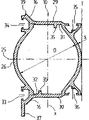
Fig. 2 is the cross sectional drawing with elevator of guide and mass;
Fig. 3 is the cross sectional drawing that crosses guidance type spare;
Fig. 4 is the cross sectional drawing that has the guidance type spare of mass, service cover, connecting strap and drive wheel and bogie wheel;
Fig. 5 is the lateral plan of mass;
Fig. 6 is a lateral plan of loading onto the guide of connecting strap, infrastructure component, service cover and shock absorber.
Fig. 1 illustrates and guide 10 bonded assembly elevators, and this guide stretches out on the outer wall 2 that fixation kit is connected building 1 by telescopic.Building has floor 3.Elevator case 5 with self actuator is configured between the guide 10.The end of guide 10 at the top be top assembly 13 and link together in side direction and top 13, and the end in the bottom is to stand on the infrastructure component 12 on the building basal surface 4 and link together with this infrastructure component 12.Elevator case 5 comprises the respective drive wheel 7 of bottom, front side and the bolster 8 at downside rear portion.The hitch point of corresponding three rollers guide 9 and load carrier 19 lays respectively at the both sides of elevator case 5 upper surfaces.Load carrier 19 is guided to respectively on the elevator top assembly 13, guides on the mass 18 of operation in guide 10 by deflection roller 14 again.Speed restrictor 15 still is configured on the top assembly 13 of elevator in addition.
Fig. 2 illustrates the cross-sectional plane of elevator, can see the member of the bearing frame 6 with linkage component 23 on elevator case 5.Bearing frame 6 is configured in the place ahead of guide axis 25.The member of bearing frame 6 is cut slightly, so as can to see guide 10 structural type spare cross-sectional plane and therein the operation mass 18.The elevator information components represents with 65, and it is configured on the connection stay of the fixation kit 11 that the telescopically of level stretches out.The elevator information components of elevator case side represents with 66, and it is configured in and the elevator information components 65 very closely-spaced position that is separated by, and preferably is configured in the top of elevator case 5.Building 1 comprises the door 22 of the elevator of each floor 3.Elevator case 5 comprises elevator chamber door 21.
The following details that the type spare cross-sectional plane of guide 10 is described with reference to Fig. 3.Type spare comprises empty interior circular diameter D, has continuous basically wall thickness S.The center of basic configuration is the intersection point of guide axis 25 and X-axis line rectangular with it.Above the guide axis 25 outside the flat rolling surface 29 that is used for bogie wheel 8 is formed in and is positioned at, the flat rolling surface 30 that is used for drive wheel 7 be formed on guide axis 25 below, two rolling surfaces all are parallel to guide axis 25 and extend, each all straight extension, equidistant with this axle, its spacing is about the length of D/2.Form the rolling surface 16 that two other is used to be configured in the guide roller 9 of elevator case upside, this rolling surface 16 about 45 that tilts up and down respectively, and combine at the left-hand side of flat rolling surface 29 and 30.The cylindrical outside wall of left-hand side also comprises the 3rd flat rolling surface 26, and the three rollers of the three rollers guide 9 on elevator case 5 is symmetrical in guide axle 25 and rolls along the 3rd rolling surface.Form four anchor groove 33,34,35 and 36 at the rolling surface 29 in the type spare outside and a side of 30.Anchor groove 33,34,35 and 36 has limb shape spare, and this limb shape spare surrounds empty space respectively, and can be in the back by grappling slide block or flute profile strip engagement.Anchor groove 35 and 36 has opposite channel opening mutually, and its center line parallel extends in the X-axis line.Anchor groove 35 and 36 right-hand side to outward flange against vertical tangent line T.Anchor groove 35 and 36 front surface are parallel to rolling surface 29 and 30 respectively, but with respect to the latter a little by the back.Anchor groove 33 and 34 axis and guide axis spare 25 are equidistant and be parallel to this axis, and anchor groove 33 and 34 opening are respectively left towards the outside.Anchor groove 33 and 34 front surface retreat the thickness S of about twice wall with respect to the arc of outer wall surface.The antetheca of anchor groove 33 prolongs downwards, is parallel to X-axis, forms parallel braking limb 37, and S compares with wall thickness, and this limb has thick slightly thickness.Form the short portion that extends upward 39 at the top of anchor groove 34 side, so that fully widen the width of rolling surface 16.
Back in type spare inboard in anchor groove 33 and 34 forms guide groove 32 and 31.The bottom land of guide groove 31 is formed by the plane outer wall of type spare, and the right hand cell wall of guide groove 31 is made of the wall that surrounds anchor groove 35, and its left hand cell wall is made of a rib 39, and this rib vertically downward.The bottom land of guide groove 32 is formed by the flat outer wall of type spare, and the left-hand side cell wall of this guide groove 32 is made of the wall that surrounds anchor groove 33, and its right-hand side cell wall is formed by a rib 38, and this rib vertically upward.Except that cell wall 31, the interior profile of type spare is parallel to rolling surface 29 and extends, and extends to the bottom side of anchor groove 34, except that guide groove 32, the interior profile of type spare is parallel to rolling surface 30 and extends a little part, extends to a step, and this step tangentially carries out the transition to the interior circle that diameter is D then.
Fig. 4 illustrates the cross sectional drawing of the guide 10 that mass 18 moves therein.Flute profile strip 40 is pushed in the anchor groove 33, and with screw 42 itself and connecting strap 41 is linked together.Type spare between anchor groove 33 and 34 partly is a service cover 43, and when removing connecting strap at joint 58,59 places, this service cover can be by joint 58 and 59 and partly separate with remaining type spare.47 expression mass unit, it is circular basically, but is cut flat at side, and be broadened again in the place ahead of two lateral sections that are positioned at side, so that constitute corresponding butt joint, fore arch section has hold down groove 60, and the fixed part 55 of T shape is engaged in this groove.The side plate 49 that supporting enters the slide-and-guide parts 54 of guide groove 31 and 32 is fixed on the lateral parts 56.Along the bogie wheels of rolling surface 29 and 30 rollings and the outside that the drive wheel parts are shown in guide 10.
Fig. 5 illustrates the lateral plan of whole mass 18.Lateral parts 56 by lower tie plate 52 and from the bottom second adapter plate 53 of number and linking together upwards with bottom level, by top tie plate 50 and from the top second adapter plate 51 of number and linking together downwards with top, horizontal.
Fig. 6 illustrates the view laterally of guide 10 bottoms.The bottom of guide 10 is connected on the thick column piece 61 securely, and this thick column piece is by connecting strap 41, screw 42 and flute profile strip 40 formation base assemblies.At height h
1Above, level is cut the type spare front side arch section of guide 10 between joint 58 and 59.This above first horizontal section 62 another the height h
2Be in and form second horizontal section 63 between joint 58 and 59.Can part from that part of section of taking out between two joints 58 and 59 and two horizontal sections 62 and 63 and constitute service cover 43 now.When the state that has inserted, service cover 43 is connected on the type spare of guide 10 securely by the connecting strap 41 that is contained in four angles and is contained in intermediate altitude.At a little higher than h
1Height, with the inside that deformation part 46 inserts guides 10, its upper end face is covered by pressure plate 44.And then resilient snubber 45 is stacked on the pressure plate 44.
Owing to when taking off service cover, form opening, so can at first put into deformation part 46, be placed in the substrate, load onto pressure plate 44 at its top then.Subsequently the resilient snubber 45 of calculating number is overlayed pressure plate 44 above.Can lead to service ports now will be put into by the mass framework 64 that does not comprise sliding guide piece 54 that lateral parts 56, adapter plate 50,51,52,53 are formed, and be put on the resilient snubber 45.Forward mass framework 64 to tram then, widen, thereby this sliding guide piece is screwed on guide groove 31 and 32 and enters this groove mass 18 can not be rotated with slide-and-guide parts 54.The size of crossing lateral parts 56 is slightly smaller than basic circle diameter D, and when therefore not having sliding guide piece 54, mass framework 64 may rotate.The size of mass framework is definite like this, makes its height dimension a lot of mass unit of can packing into, and for example, making that the net weight of elevator case 5 adds 25% load can be by mass 18 compensation on both sides.Mass 18 just is connected with load carrier 19 before being preferably in and being encased in service hatch.After the mass unit 47 of the needs of packing into, insert clam member 48, make it push down mass unit 47, fastening then fixed part 55, and utilize service cover 43 to close service ports again, by connecting strap 41, screw 42 and flute profile strip 40 this lid is firmly fixed.
The top assembly 13 that the constitutes guide 10 upper ends thick column piece 61 by down in a similar fashion utilizes connecting strap 31, is connected on the guide 10.Under the situation of using unpowered elevator case, the CD-ROM drive motor of band drive wheel etc. also can be admittedly on top assembly 13.
In simple embodiment more, band can replace top assembly 13 and infrastructure component 12 with any gauge member of type that requires, carry out the horizontal connection of guide 10, for this purpose, only need utilize suitable anchor groove 33,34,35 and 36 to carry out suitable screw and be connected.
Four anchor groove that form on the type spare outer peripheral face of guide 10 and that be distributed on this outer peripheral face can be used as following purposes:
Be connected with fastening assembly 11;
Fastening service cover 43;
One of them type spare member is connected with infrastructure component 12, and is connected with top assembly 13;
Fixedly usefulness can be in the crossbeam that deflection roller etc. is installed;
Can fix the device of the elevator information relevant with elevator;
Can built in light spare;
Fixing electric power erecting device;
Generally can fix different electric and mechanicals device, for example switch cam, heating device, warning device, gargle pipe etc.;
The fixing elevator backplate of any kind of;
Can fixedly climb equipment, for example ladder;
Combine with fastening assembly, can the fixed frame pedestal.
Because use non-magnetic type spare material, so can operate the elevator information components at elevator, these parts for example are the shape of permanent magnet, can utilize flute profile strip 40 and screw element 41 directly to be fixed on the position of needs of anchor groove 33,34,35 or 36.Equally, also can dispose the elevator switch of any kind by this way, perhaps directly be configured on anchor groove 33,34,35 or 36, or be configured on its little support arm.
The braking limb shape spare 37 that is formed in anchor groove 33 next doors is surrounded by the unshowned elevator case brake equipment that is positioned on the elevator case 5, this limb shape spare is used from emergency braking elevator case 5 under the situation that speed may rise together with the chock one that shrinks when elevator case brake equipment triggers, make it be no more than command speed.Consider different requirements and make rolling surface 29,30 and the brake area on braking limb shape spare 37 separates in operation, the great advantage of this separation is, without any because of the riding traveling comfort of the surface damage of stopping brake roughen with damage coefficient of friction.The coating of stablizing coefficient of friction is added on rolling surface 29 and 30.This coating for example metallic oxide makes the coefficient of friction of rolling surface 29 and 30 be independent of this surperficial different conditions (dried, tide, wet, dirty) basically.Can adopt roller type common in the elevator industry or chock formula elevator case brake equipment to make elevator case brake equipment.Extension 39 on anchor groove 34 next doors is used to form the enough wide rolling surface 16 of guide roller 9 usefulness.
Except that above-mentioned predetermined purposes and, the anchor groove of shaping has also increased the torsional stability on all axis between axis 25 and the X.
Except that anchor groove 33,34,35 and 36, the dagger of fastening assembly 11 also can be used as different fastening functional components.Because the fastening assembly that these sleeve-types stretch out preferably is configured in the doorway of each floor 3, so their triatic stay can be used to ideally dispose and fix the elevator information data relevant with floor for example raft of pontoons zone, last control band and zero floor area.In addition, at assembly process, they can be used as the framework pedestal, and are temporary transient as supporting.
The intensity of the guiding limb shape spare of the intensity of guide 10 or braking limb shape spare 37 and the shape guide rail of standard is suitable.The most handy non-metals or fiber-reinforced composite material are made the structural materials of guide 10.In the form that another kind proposes, the second braking limb shape spare 37 can be shaped.
For example can make deformation part 46 with the honeycomb cellular structure member of doing by suitable material with vertical junction member.Because abnormal thump will be for example because under the situation of the possible deformation that the thump that load carrier 19 or the fracture of its fastener produce causes, a unshowned safety switch will be driven.
The resilient snubber 45 that overlays on the pressure plate 44 has suitable intrinsic damping behavior and elastomeric synthetic or natural rubber type of material making for adapting to corresponding load, adopting.
Claims (7)
1. one kind is used to lead and makes a gift to someone or the ways of service elevator, this guide frame comprises two cylindricality guides (10), the elevator case (5) that has own actuator moves on this guide and is directed to, wherein, guide (10) is made to load bearing component, comprise and be used for drive wheel (7), the flat rolling surface (29 of bogie wheel (8) and guide roller (9), 30,16,25), some anchor groove (33,34,35,36) be located at rolling surface (29,30) outside, anchor groove has fastening effect and interconnect function, it is characterized in that, guide (10) is shaped as extrusion pressing type spare, comprise the braking limb shape spare (37) that is used to mesh brake equipment or elevator case lugs, it asymmetricly stretches out the cross section of guide (10) on the whole length of guide (10).
2. elevator guide frame as claimed in claim 1 is characterized in that, the extrusion pressing type spare material of guide (10) is aluminium or light-metal alloy.
3. elevator guide frame as claimed in claim 1, it is characterized in that, guide (10) is connected by top assembly (13) and infrastructure component (12), and wherein top assembly (13) comprises the thick column piece (61) identical with the type spare of guide (10) with infrastructure component (12).
4. as the described elevator guide frame of above-mentioned claim 1, it is characterized in that, the type spare of guide (10) is made to hollow, its inside comprises that at least one is used for the guide groove of mass (18) (31,32), this mass (18) is connected with elevator case (5), operation in guide (10).
5. elevator guide frame as claimed in claim 4 is characterized in that, the type spare of guide (10) comprises at least one service cover (43), and this lid is configured between two anchor groove (33,34), can open and close a service ports.
6. elevator guide frame as claimed in claim 5 is characterized in that, mass (18) is introduced by described service ports.
7. elevator guide frame as claimed in claim 5 is characterized in that, guide (10) comprises damper element (44,46,62), and it is arranged on the bottom of guide (10) hollow space, and this damper element is introduced by service ports.
Applications Claiming Priority (2)
| Application Number | Priority Date | Filing Date | Title |
|---|---|---|---|
| CH162495 | 1995-06-02 | ||
| CH01624/95 | 1995-06-02 |
Publications (2)
| Publication Number | Publication Date |
|---|---|
| CN1142463A CN1142463A (en) | 1997-02-12 |
| CN1044591C true CN1044591C (en) | 1999-08-11 |
Family
ID=4214801
Family Applications (1)
| Application Number | Title | Priority Date | Filing Date |
|---|---|---|---|
| CN96107777A Expired - Fee Related CN1044591C (en) | 1995-06-02 | 1996-05-30 | Guide structure for lift |
Country Status (13)
| Country | Link |
|---|---|
| US (1) | US5725074A (en) |
| EP (1) | EP0745550B1 (en) |
| JP (1) | JPH08324917A (en) |
| CN (1) | CN1044591C (en) |
| AT (1) | ATE212947T1 (en) |
| BR (1) | BR9602584A (en) |
| CA (1) | CA2177791A1 (en) |
| DE (1) | DE59608694D1 (en) |
| DK (1) | DK0745550T3 (en) |
| ES (1) | ES2172609T3 (en) |
| HK (1) | HK1011338A1 (en) |
| NO (1) | NO962246L (en) |
| PT (1) | PT745550E (en) |
Families Citing this family (18)
| Publication number | Priority date | Publication date | Assignee | Title |
|---|---|---|---|---|
| DK0846645T3 (en) * | 1996-12-03 | 2004-11-15 | Inventio Ag | Modularly built elevator |
| US5899300A (en) * | 1996-12-20 | 1999-05-04 | Otis Elevator Company | Mounting for an elevator traction machine |
| DE29924745U1 (en) * | 1998-02-26 | 2005-06-09 | Otis Elevator Co., Farmington | Directional match of flat ropes for elevators |
| DE29924761U1 (en) * | 1998-02-26 | 2005-06-23 | Otis Elevator Co., Farmington | Elevator system having drive motor located between elevator car and hoistway side wall |
| DE29817520U1 (en) * | 1998-05-13 | 1999-12-02 | Rud Prey Gmbh Aufzuege Und Feu | Elevator |
| US6085874A (en) * | 1998-12-22 | 2000-07-11 | Otis Elevator Company | Rail-climbing elevator counterweight having flat machines |
| WO2002022485A1 (en) | 2000-09-12 | 2002-03-21 | Kone Corporation | Supporting structure for elevator guide rails |
| WO2006078579A2 (en) * | 2005-01-18 | 2006-07-27 | Teleflex, Incorporated | Pedal kickdown mechanism and treadle attachment mechanism |
| EP2134637B1 (en) * | 2007-03-12 | 2014-07-23 | Otis Elevator Company | Machine mounting in a machine roomless elevator system |
| US20090032340A1 (en) * | 2007-07-31 | 2009-02-05 | Rory Smith | Method and Apparatus to Minimize Re-Leveling in High Rise High Speed Elevators |
| ES2509352T3 (en) * | 2008-05-16 | 2014-10-17 | Thyssenkrupp Elevator Ag | Longitudinal bar element for an elevator installation box |
| EP2303750B1 (en) * | 2008-07-23 | 2013-10-09 | Inventio AG | Elevator assembly with self-driving elevator cabin |
| CN102105381A (en) * | 2008-07-23 | 2011-06-22 | 因温特奥股份公司 | Elevator system with automotive counterweight |
| ES2356204B1 (en) * | 2008-11-26 | 2012-02-13 | Orona, S. Coop | GUIDING SYSTEM FOR LIFTING EQUIPMENT, LIFTING EQUIPMENT AND METHOD FOR ASSEMBLING SUCH GUIDING SYSTEM. |
| CA3121416A1 (en) * | 2018-12-20 | 2020-06-25 | Inventio Ag | Elevator rail |
| CN112678652B (en) * | 2020-12-30 | 2021-08-17 | 亚洲富士电梯股份有限公司 | Elevator and efficient construction equipment and construction method thereof |
| EP4269313A1 (en) * | 2022-04-25 | 2023-11-01 | Thoma Aufzüge GmbH | Universal elevator |
| CN115973948B (en) * | 2023-01-31 | 2023-07-25 | 江苏博涛智能热工股份有限公司 | Passageway conveying platform with lifting function |
Citations (2)
| Publication number | Priority date | Publication date | Assignee | Title |
|---|---|---|---|---|
| US3814027A (en) * | 1972-11-14 | 1974-06-04 | R Vice | Guide track for a stairway elevator |
| US5284226A (en) * | 1991-12-11 | 1994-02-08 | Daifuku Co., Ltd. | Carriage guiding post in a transfer lifter |
Family Cites Families (2)
| Publication number | Priority date | Publication date | Assignee | Title |
|---|---|---|---|---|
| DE1506479A1 (en) * | 1967-06-14 | 1969-12-18 | Hans Mangelsdorff | Elastic headstock chain drive, especially for industrial and garage lifts |
| DE9302119U1 (en) * | 1993-02-15 | 1993-04-01 | C. Haushahn Gmbh & Co, 7000 Stuttgart, De |
-
1996
- 1996-05-13 US US08/645,409 patent/US5725074A/en not_active Expired - Fee Related
- 1996-05-22 DE DE59608694T patent/DE59608694D1/en not_active Expired - Fee Related
- 1996-05-22 EP EP96108133A patent/EP0745550B1/en not_active Expired - Lifetime
- 1996-05-22 PT PT96108133T patent/PT745550E/en unknown
- 1996-05-22 DK DK96108133T patent/DK0745550T3/en active
- 1996-05-22 AT AT96108133T patent/ATE212947T1/en not_active IP Right Cessation
- 1996-05-22 ES ES96108133T patent/ES2172609T3/en not_active Expired - Lifetime
- 1996-05-30 CN CN96107777A patent/CN1044591C/en not_active Expired - Fee Related
- 1996-05-30 CA CA002177791A patent/CA2177791A1/en not_active Abandoned
- 1996-05-31 BR BR9602584A patent/BR9602584A/en not_active Application Discontinuation
- 1996-05-31 NO NO962246A patent/NO962246L/en not_active Application Discontinuation
- 1996-05-31 JP JP8139001A patent/JPH08324917A/en active Pending
-
1998
- 1998-11-26 HK HK98112335A patent/HK1011338A1/en not_active IP Right Cessation
Patent Citations (2)
| Publication number | Priority date | Publication date | Assignee | Title |
|---|---|---|---|---|
| US3814027A (en) * | 1972-11-14 | 1974-06-04 | R Vice | Guide track for a stairway elevator |
| US5284226A (en) * | 1991-12-11 | 1994-02-08 | Daifuku Co., Ltd. | Carriage guiding post in a transfer lifter |
Also Published As
| Publication number | Publication date |
|---|---|
| CA2177791A1 (en) | 1996-12-03 |
| US5725074A (en) | 1998-03-10 |
| CN1142463A (en) | 1997-02-12 |
| EP0745550A1 (en) | 1996-12-04 |
| NO962246D0 (en) | 1996-05-31 |
| HK1011338A1 (en) | 1999-07-09 |
| ES2172609T3 (en) | 2002-10-01 |
| EP0745550B1 (en) | 2002-02-06 |
| DE59608694D1 (en) | 2002-03-21 |
| PT745550E (en) | 2002-07-31 |
| ATE212947T1 (en) | 2002-02-15 |
| JPH08324917A (en) | 1996-12-10 |
| DK0745550T3 (en) | 2002-05-27 |
| BR9602584A (en) | 1998-10-06 |
| NO962246L (en) | 1996-12-03 |
Similar Documents
| Publication | Publication Date | Title |
|---|---|---|
| CN1044591C (en) | Guide structure for lift | |
| CN100347068C (en) | Elevator system having drive motor located between elevator car and hoistway sidemall | |
| CN1081162C (en) | Elevator machinery and its installation | |
| US6193017B1 (en) | Pulley-driven elevator | |
| CN112550340B (en) | Bogie and rail vehicle | |
| CN101588981B (en) | Self-supporting elevator car | |
| KR101956184B1 (en) | System of vertical and horizontal movement of the transport cabin in a elevator translator plant for the overcoming of obstacles | |
| CN1239376C (en) | Cage device for double deck elevators | |
| JP2000153975A (en) | Elevator with tow sheave | |
| CN101074078A (en) | Elevator crane bridging system | |
| PT1397304E (en) | Elevator | |
| CN101054793A (en) | Middle and low speed magnetic levitation track girder | |
| CA2455957A1 (en) | Counterbalanced deck for railroad freight car | |
| CN1081423A (en) | Be used for the particularly actuating device of passenger-goods lift of lifting means | |
| US20060175140A1 (en) | Pulley arrangement for elevators | |
| CN114084189B (en) | Bogie with side beam fixing seat and railway vehicle | |
| US10450168B2 (en) | Double deck elevator system | |
| EP1602614A1 (en) | Elevator equipment | |
| CN1094109C (en) | Cable-driven elevator | |
| JPH11240678A (en) | Elevator counterweight | |
| CN1053426C (en) | Elevator having an elevator cage guided in rucksa CK-type manner on a mount frame | |
| CN209081190U (en) | A kind of guide wheel of elevator device | |
| CN220950765U (en) | Elevator counterweight device for improving space utilization rate | |
| CN218088479U (en) | Be applied to damping spring floorbar of taking advantage of elevator car frame | |
| CN1656006A (en) | Method for making an elevator and system for elevator delivery |
Legal Events
| Date | Code | Title | Description |
|---|---|---|---|
| C10 | Entry into substantive examination | ||
| SE01 | Entry into force of request for substantive examination | ||
| C06 | Publication | ||
| PB01 | Publication | ||
| C14 | Grant of patent or utility model | ||
| GR01 | Patent grant | ||
| C19 | Lapse of patent right due to non-payment of the annual fee | ||
| CF01 | Termination of patent right due to non-payment of annual fee |