CN114084189B - Bogie with side beam fixing seat and railway vehicle - Google Patents
Bogie with side beam fixing seat and railway vehicle Download PDFInfo
- Publication number
- CN114084189B CN114084189B CN202111402596.4A CN202111402596A CN114084189B CN 114084189 B CN114084189 B CN 114084189B CN 202111402596 A CN202111402596 A CN 202111402596A CN 114084189 B CN114084189 B CN 114084189B
- Authority
- CN
- China
- Prior art keywords
- side beam
- bogie
- plate
- transverse
- stop
- Prior art date
- Legal status (The legal status is an assumption and is not a legal conclusion. Google has not performed a legal analysis and makes no representation as to the accuracy of the status listed.)
- Active
Links
Images


Classifications
-
- B—PERFORMING OPERATIONS; TRANSPORTING
- B61—RAILWAYS
- B61F—RAIL VEHICLE SUSPENSIONS, e.g. UNDERFRAMES, BOGIES OR ARRANGEMENTS OF WHEEL AXLES; RAIL VEHICLES FOR USE ON TRACKS OF DIFFERENT WIDTH; PREVENTING DERAILING OF RAIL VEHICLES; WHEEL GUARDS, OBSTRUCTION REMOVERS OR THE LIKE FOR RAIL VEHICLES
- B61F5/00—Constructional details of bogies; Connections between bogies and vehicle underframes; Arrangements or devices for adjusting or allowing self-adjustment of wheel axles or bogies when rounding curves
- B61F5/50—Other details
- B61F5/52—Bogie frames
- B61F5/523—Bogie frames comprising parts made from fibre-reinforced matrix material
-
- B—PERFORMING OPERATIONS; TRANSPORTING
- B61—RAILWAYS
- B61F—RAIL VEHICLE SUSPENSIONS, e.g. UNDERFRAMES, BOGIES OR ARRANGEMENTS OF WHEEL AXLES; RAIL VEHICLES FOR USE ON TRACKS OF DIFFERENT WIDTH; PREVENTING DERAILING OF RAIL VEHICLES; WHEEL GUARDS, OBSTRUCTION REMOVERS OR THE LIKE FOR RAIL VEHICLES
- B61F5/00—Constructional details of bogies; Connections between bogies and vehicle underframes; Arrangements or devices for adjusting or allowing self-adjustment of wheel axles or bogies when rounding curves
- B61F5/50—Other details
-
- Y—GENERAL TAGGING OF NEW TECHNOLOGICAL DEVELOPMENTS; GENERAL TAGGING OF CROSS-SECTIONAL TECHNOLOGIES SPANNING OVER SEVERAL SECTIONS OF THE IPC; TECHNICAL SUBJECTS COVERED BY FORMER USPC CROSS-REFERENCE ART COLLECTIONS [XRACs] AND DIGESTS
- Y02—TECHNOLOGIES OR APPLICATIONS FOR MITIGATION OR ADAPTATION AGAINST CLIMATE CHANGE
- Y02T—CLIMATE CHANGE MITIGATION TECHNOLOGIES RELATED TO TRANSPORTATION
- Y02T30/00—Transportation of goods or passengers via railways, e.g. energy recovery or reducing air resistance
Abstract
The embodiment of the application provides a bogie and rail vehicle with curb girder fixing base, wherein, the bogie includes: two side beams arranged side by side; a transverse connection for connecting the two side beams; the transverse connecting device is positioned below the two side beams; the fixing seat is spanned above the side beams, and the two transverse ends of the fixing seat extend downwards from the two sides of the side beams to be connected with the transverse connecting device. The bogie and the railway vehicle provided by the embodiment of the application are beneficial to improving the driving safety.
Description
Technical Field
The application relates to a vehicle running technology, in particular to a bogie with a side beam fixing seat and a railway vehicle.
Background
The bogie is an important component of the railway vehicle for carrying the vehicle body and for performing the running and steering functions. The bogie comprises a framework, a wheel set, a traction device, a buffer device and other structures, the framework commonly used generally comprises two side beams extending along the length direction of the vehicle and a cross beam connecting the two side beams, and the cross beam and the side beams are connected in various modes. After studying various forms of bogies, the skilled person has found that conventional bogies suffer from technical drawbacks, such as: the dead weight is large, so that the acting force of the wheel set is large, the abrasion of the wheel rail is large, and larger noise is generated; the framework is rigidly connected, so that the vibration reduction capability is poor, the carriage is larger in vibration, and the riding comfort is poor; the wheel weight load shedding rate is high, and the safety is reduced; the problem that anti roll ability is relatively poor makes the carriage easily take place to turn on one's side, and vertical buffer capacity is insufficient and leads to the carriage vibration great and makes the ride comfort degree relatively poor, and the dead weight is great and leads to traction efficiency lower, leads to assembly efficiency lower etc. because of the part installation overall arrangement is unreasonable.
Disclosure of Invention
In order to solve one of the technical defects, the embodiment of the application provides a bogie with a side beam fixing seat and a railway vehicle.
According to a first aspect of embodiments of the present application, there is provided a bogie with a side beam fixing base, comprising:
two side beams arranged side by side;
a transverse connection for connecting the two side beams; the transverse connecting device is positioned below the two side beams;
the fixing seat is spanned above the side beams, and the two transverse ends of the fixing seat extend downwards from the two sides of the side beams to be connected with the transverse connecting device.
According to a second aspect of embodiments of the present application, there is provided a rail vehicle comprising: a bogie with side beam mounts as described above.
According to the technical scheme, the side beams and the transverse connecting devices connected between the side beams are arranged side by side, the transverse connecting devices are located below the side beams, the fixing base stretches across the upper portion of the middle of the side beams, the two sides of the side beams extend downwards to be connected with the transverse connecting devices, the fixing base can limit the side beams, the weight of a vehicle body can be borne under the limit condition, the whole failure of a bogie is avoided, and the driving safety is improved.
Drawings
FIG. 1 is a schematic view of a single-layer side sill non-power bogie provided in an embodiment of the present application;
FIG. 2 is a top view of a single-layer side sill non-power bogie provided in an embodiment of the present application;
FIG. 3 is a schematic view of a single-layer side sill power bogie provided in an embodiment of the present application;
FIG. 4 is a top view of a single-layer side sill power bogie provided in an embodiment of the present application;
FIG. 5 is a schematic view of a dual-deck side sill non-power bogie provided in an embodiment of the present application;
FIG. 6 is a top view of a dual-layer side sill non-power bogie provided in an embodiment of the present application;
FIG. 7 is a schematic structural view of a dual-deck side sill power bogie provided in an embodiment of the present application;
FIG. 8 is a top view of a dual-layer side sill power bogie provided in an embodiment of the present application;
fig. 9 is a schematic structural view of a connecting seat in a bogie according to an embodiment of the present application;
FIG. 10 is a schematic view of a two-layer side sill in a truck provided in an embodiment of the present application;
FIG. 11 is an exploded view of a double-layered side sill and hitch seat assembly in a truck provided in an embodiment of the present application;
FIG. 12 is a schematic view of a two-layer side sill in a truck provided in an embodiment of the present application subjected to a first vertical load;
FIG. 13 is a schematic illustration of a two-layer side sill in a truck provided in an embodiment of the present application subjected to a second vertical load;
fig. 14 is a schematic structural view of a wheel set in a bogie according to an embodiment of the present application;
FIG. 15 is a schematic view of a primary suspension device in a bogie according to an embodiment of the present disclosure;
FIG. 16 is a schematic view of a safety stop assembly in a truck provided in an embodiment of the present application;
FIG. 17 is a cross-sectional view of a safety stop assembly in a truck provided in an embodiment of the present application;
FIG. 18 is an exploded view of a safety stop assembly in a truck provided in an embodiment of the present application;
FIG. 19 is a cross-sectional view of a secondary suspension device and connection mount assembly in a truck provided in an embodiment of the present application;
FIG. 20 is a schematic view of a secondary suspension device and a connection base assembly in a bogie according to an embodiment of the present disclosure;
FIG. 21 is a schematic structural view of a brake device and a connection seat assembly in a bogie according to an embodiment of the present disclosure;
fig. 22 is a schematic structural diagram of a bogie axle box and a connection seat connected by a single tie rod according to an embodiment of the present disclosure;
FIG. 23 is an exploded view of an axle housing and connection mount for a truck in accordance with an embodiment of the present application connected by a single tie rod;
fig. 24 is a schematic structural view of a traction device connected to a connection seat in a bogie according to an embodiment of the present application;
FIG. 25 is an exploded view of a truck draft gear attached to a hitch base provided in an embodiment of the present application;
FIG. 26 is a schematic view of the structure of a kingpin in a truck provided in an embodiment of the present application;
FIG. 27 is a side view of a kingpin in a truck provided in an embodiment of the present application;
FIG. 28 is a schematic structural view of a transverse shock absorber assembly in a truck provided in an embodiment of the present application;
fig. 29 is a schematic structural view of an assembly of a driving device and a connection seat in a bogie according to an embodiment of the present application;
FIG. 30 is a top view of a truck drive assembly and connection block assembly provided in accordance with an embodiment of the present disclosure;
FIG. 31 is a schematic view of a side sill in another truck provided in an embodiment of the present application;
fig. 32 is a schematic structural view of a connecting seat in another bogie according to an embodiment of the present application;
FIG. 33 is an exploded view of an alternative truck side sill and hitch mount assembly provided in accordance with an embodiment of the present application;
FIG. 34 is a schematic view of an alternative truck side sill and primary suspension assembly configuration in accordance with an embodiment of the present application;
FIG. 35 is a cross-sectional view of another truck side sill in accordance with an embodiment of the present application assembled with a primary suspension;
fig. 36 is an exploded view of another truck side sill and primary suspension assembly provided in accordance with an embodiment of the present application.
Reference numerals:
1-side beams; 11-upper side beam plates; 12-lower side beam plates;
2-connecting seats; 21-a first side beam mounting groove; 22-fixing seats; 221-fixing bolts; 222-a first upper liner; 223-a first underlayment; 23-two-system mounting seats; 231-second series positioning holes; 24-braking hanging seat; 241—hanger mounting holes; 25-connecting the side walls by the pull rod; 251-tie rod mounting holes; 261-first connection portion; 2611-a first central bore; 2612-first bolt hole; 262-a second connection; 2621-a second central bore; 2622-second bolt holes; 27-a lateral stop; 28-a motor mounting portion; 29-first side sill mounting bosses;
31-axle; 32-wheels; 33-axle boxes; 331-a series of positioning holes; 332-lifting the edge; 333-lifting notch; 334-tie rod connection socket; 34-single pull rod; 341-elastic nodes;
4-traction means; 41-a traction beam; 411-beam body; 412-a first connection disc; 413—a first connection bolt; 414-connecting pins; 415-elastic buffer sleeve; 416-a connection flange; 417-second connecting bolts; 42-a traction pin; 421-body connection; 422-lifting arm; 4221-damper assembly space; 4222-damper mounting holes; 43-longitudinal stop assembly; 431-inner mount; 432-longitudinal stops; 433-outside mount; 44-a transverse stop assembly;
5-a primary suspension device; 51-an elastic buffer; 52-side beam mounting portions; 521-second side rail mounting slots; 522—a safety stop mounting hole; 53-safety stop; 531-first stop shelf; 532—a second stop frame; 533-stop connecting bolt; 54-a second underlayment; 55-lifting and hanging parts; 56-a tie down assembly;
6-a secondary suspension device; 61-a secondary positioning pin;
71-a direct drive motor; 72-a motor balance bar;
8-a braking device;
91-a damper integration base; 92-transverse vibration dampers; 93-antihunting damper; 94-vertical vibration damper; 95-anti-roll torsion bar.
Detailed Description
The embodiment provides a bogie with a side beam fixing seat, which can be applied to a railway vehicle. In the present embodiment, the vehicle length direction is referred to as the longitudinal direction, the vehicle width direction is referred to as the lateral direction, and the vehicle height direction is referred to as the vertical direction, or the vertical direction.
Fig. 1 is a schematic structural view of a single-layer side-beam non-power bogie provided in an embodiment of the present application, and fig. 2 is a top view of the single-layer side-beam non-power bogie provided in an embodiment of the present application. As shown in fig. 1 and 2, the present embodiment provides a bogie including: side beam 1, transverse connection means and fixing base 22.
Wherein the side members 1 extend in the longitudinal direction in two numbers, arranged side by side. The transverse connection is connected between the two side beams 1. The transverse connection means may be a cross member, a sleeper beam, a hinged cross member or the like connected between the two side members 1.
The transverse connecting device is positioned below the side beam 1, the fixed seat 22 spans above the side beam 1, and the transverse two ends of the fixed seat 22 extend downwards from the two sides of the side beam 1 to be connected with the transverse connecting device. The fixing seat 22 is connected with the transverse connecting device, and can transversely limit the side beam 1 and fix the relative position of the side beam 1. The fixing base 22 can also support the vehicle body in extreme situations, for example: after the vertical buffering part is damaged, the car body falls and contacts with the fixing seat 22, and the fixing seat 22 supports the car body, so that the car can run to a station or a maintenance station at a low speed, and the safety of personnel in the car is ensured.
The technical scheme that this embodiment provided, including the curb girder that sets up side by side and connect the transverse connection device between the curb girder, transverse connection device is located the below of curb girder, and the fixing base spanes in the top at the curb girder middle part, extends to link to each other with transverse connection device downwards from the both sides of curb girder, and the fixing base can carry out spacing to the curb girder, and can bear the automobile body weight under the extreme condition, avoids the whole inefficacy of bogie, improves driving safety.
For the above technical solutions, the present embodiment provides several specific implementations:
as shown in fig. 1 and 2, two connecting seats 2 are adopted, one connecting seat 2 is arranged below the middle part of one side beam 1, and the connecting seat 2 is used for supporting the side beam 1. The traction device 4 is connected between the two connecting seats 2, and the traction device 4 is also used for being connected with the car body of the railway car and transmitting longitudinal traction force and braking force between the car body and the bogie. The connecting seat 2 and the traction device 4 serve as the above-mentioned transverse connecting means, and are connected between the two side members 1.
The number of wheel sets is two, sets up respectively in the tip below of curb girder 1, and the wheel set includes: axle 31, wheels 32 symmetrically disposed on axle 31, and axle boxes 33.
A primary suspension 5 is provided between the axle housing 33 and the end of the side member 1 for supporting the side member 1 and for damping the vertical force between the side member 1 and the wheel set 3.
Further, the device also comprises a secondary suspension device 6, wherein the secondary suspension device 6 is arranged on the connecting seat 2 and is positioned outside the side beam 1. The secondary suspension device 6 is used for supporting the vehicle body and buffering the vertical force between the vehicle body and the bogie. In conventional bogies, the secondary suspension device 6 is typically provided at the top of the side sill or at the top of the bolster. Unlike conventional bogies are: in the bogie proposed in the present application, the secondary suspension device 6 is provided on the connection base 2 without a direct connection relationship with the side member 1.
The bogie provided by the scheme abandons the traditional beam structure, adopts the connecting seat for connecting and fixing the side beams, adopts the traction device to connect the two connecting seats together, can greatly reduce the weight of the bogie, and is beneficial to improving the traction efficiency of the railway vehicle. The connecting seat is provided with a plurality of interfaces for connecting the side beams, the traction device, the secondary suspension device and other parts, and the structure of the bogie is simplified on the basis of meeting the basic functions of the bogie, thereby being beneficial to lightweight design.
When no drive is provided on the bogie, the bogie acts as a non-power bogie. When the driving means is provided on the bogie, the bogie acts as a power bogie. Fig. 3 is a schematic structural view of a single-layer side beam power bogie provided in an embodiment of the present application, and fig. 4 is a top view of the single-layer side beam power bogie provided in an embodiment of the present application. As shown in fig. 3 and 4, the driving device includes: a direct drive motor 71 and a motor balance bar 72. The direct drive motor 71 is disposed on the axle 31, the rotor is connected to the axle 31, and the stator of the direct drive motor 71 is fixedly connected to the housing. The connection base 2 also provides a connection interface with the direct drive motor 71, and the housing of the direct drive motor 71 is connected with the connection base 2 through a motor balance rod 72. The housing of the direct drive motor 71 is fixed to the axlebox 33 via a motor end cover. The axle 31 is directly driven to rotate by the direct drive motor 71, so that a gear reducer in a traditional bogie is omitted, the structure of the bogie is further simplified, and the weight of the bogie is reduced.
Further, the bogie further comprises a braking device 8 for braking the wheels 32. In this embodiment, the braking device 8 is fixed to the connection base 2 using a brake caliper. During braking, the brake calipers clamp the disc faces on both sides of the wheel 32 for braking.
The side member 1 may be a single-layer side member, and the thickness of the side member 1 gradually decreases in a direction from the middle to the end of the side member 1, that is: the side member 1 has a shape with a thick middle and thin ends. Fig. 1 to 4 show a bogie with a single-layer side sill.
Alternatively, the side member 1 may be a double-layered side member including: and the upper side beam plate and the lower side beam plate are arranged in a stacked manner, the upper side beam plate is contacted with the middle part of the lower side beam plate, and a gap is reserved between the end parts. The upper side beam plate and the lower side beam plate are both in a shape with thick middle and thin two ends, and when the load of the vehicle body is small, the upper surfaces of the upper side beam plate and the lower side beam plate are planes and extend along the horizontal direction. Fig. 5 is a schematic structural view of a dual-layer side-beam non-power bogie provided in an embodiment of the present application, fig. 6 is a top view of the dual-layer side-beam non-power bogie provided in an embodiment of the present application, fig. 7 is a schematic structural view of the dual-layer side-beam power bogie provided in an embodiment of the present application, and fig. 8 is a top view of the dual-layer side-beam power bogie provided in an embodiment of the present application. Fig. 5 to 8 show the structure of a non-power bogie and a power bogie of a double-layered side beam.
Based on the design thought, the embodiment provides a specific implementation mode of the bogie:
fig. 9 is a schematic structural diagram of a connecting seat in a bogie according to an embodiment of the present application. As shown in fig. 9, the top of the connection seat 2 is recessed downward to form a first side beam mounting groove 21, and the first side beam mounting groove 21 extends in the longitudinal direction. The middle part of the side member 1 is accommodated in the first side member mounting groove 21, and the depth of the first side member mounting groove 21 is smaller than the thickness of the middle part of the side member 1. The first side rail mounting groove 21 serves to restrict lateral displacement of the side rail 1. The double-layered side member is accommodated in the first side member mounting groove 21.
For a single-layered side sill mounting structure, it may be accommodated in the first side sill mounting groove 21; alternatively, a first side beam mounting boss may be provided on the top surface of the connection base 2, and a single-layer side beam may be provided on the first side beam mounting boss. The first side beam mounting boss is used for adjusting the height of the side beam, so that the side beam meets the mounting requirement. In this embodiment, a double-layer side beam is taken as an example, and a specific implementation manner thereof is described:
fig. 10 is a schematic structural view of a double-layered side member in a bogie provided in an embodiment of the present application, and fig. 11 is an exploded view of an assembly of the double-layered side member and a connection seat in the bogie provided in an embodiment of the present application. As shown in fig. 10 and 11, the upper side rail plate 11 and the lower side rail plate 12 are disposed in a vertically stacked relationship, each extending in the longitudinal direction, and are received in the first side rail mounting groove 21.
One implementation is as follows: the fixing seat 22 is arranged above the side beam 1 in a crossing way, and two transverse ends of the fixing seat 22 extend downwards from two sides of the side beam 1. The fixing seat 22 serves to restrict the vertical displacement of the side member 1.
Specifically, the fixing base 22 includes: fixed roof, fixed curb plate and fixing bolt. The fixed top plate extends along the direction parallel to the side beams 1, and the fixed side plates are vertically arranged at two transverse ends of the fixed top plate. The fixed side plate and the fixed top plate can be of an integrated structure, and a groove capable of accommodating the side beam is formed between the fixed top plate and the fixed side plate in a surrounding mode. The fixed top plate is approximately rectangular, and four vertex angles of the fixed top plate are in arc transition. Vertical bolt holes are formed in the four top corners, and the bolt holes extend from the top surface of the fixed top plate to the bottom surface of the fixed side plate. The fixing bolts 221 pass through bolt holes provided in the fixing top plate and the fixing side plate in sequence and then are connected to the connection base 2.
In this embodiment, the upper side rail plate 11 and the lower side rail plate 12 may be made of composite fibers, for example: carbon fiber material has certain flexible deformability. The connecting seat 2 is made of rigid materials, has certain strength and provides interfaces for other components. The holder 22 may also be made of a rigid material.
When the side beam is made of carbon fiber material, further, a first upper lining member 222 is arranged between the fixed top plate and the side beam 1 for protecting the side beam 1 from abrasion after contacting with the fixed seat 22 for a long time. In addition, a first under-lining member 223 is provided between the first side sill mounting groove 21 and the middle portion of the side sill 1 for protecting the side sill 1 from abrasion after the side sill 1 is in contact with the joint holder 3 for a long period of time.
The first lower liner 223 includes: the first lower substrate plate and the first lower substrate plate. The first lower substrate plate is disposed in parallel with the bottom surface of the first side beam mounting groove 21. The two first lower lining side plates are respectively erected on two transverse edges of the first lower lining bottom plate. The first lower liner side plate has a height greater than or equal to the depth of the first side beam mounting groove 21 so that the top end of the first lower liner side plate extends upward to cover the side surface of the lower side beam plate 12 to protect it.
The first upper liner 222 includes: a first upper liner plate and a first upper liner plate. The first upper lining bottom plate is arranged in parallel with the lower surface of the fixed top plate, and the two first upper lining side plates are respectively erected on two transverse edges of the first upper lining bottom plate. The first upper lining piece is located in the groove of the fixing seat 22, and the height of the first upper lining side plate is greater than or the same as that of the fixing side plate, so that the first upper lining side plate extends downwards to the side face of the cladding upper side beam plate 11 to protect the same.
When the upper side rail 11 and the lower side rail 12 are made of carbon fiber materials, the upper side rail 11 and the lower side rail 12 deform themselves under different loads from the vehicle body, and the vertical loads can be adjusted and buffered. Specifically, fig. 12 is a schematic view of a first vertical load applied to a double-layer side beam in a bogie according to an embodiment of the present application, and fig. 13 is a schematic view of a second vertical load applied to a double-layer side beam in a bogie according to an embodiment of the present application. It is assumed that the first vertical load is smaller than the second vertical load.
As shown in fig. 12, when the side member 1 is subjected to a smaller first vertical load, for example: the vehicle is in an empty state, the top surfaces of the upper side rail plate 11 and the lower side rail plate 12 are small deformation surfaces, and a side rail gap 13 between the two ends is large. The support rigidity is now provided solely by the upper side beam plate 11.
As shown in fig. 13, when the side member 1 is subjected to a larger second vertical load, for example: the vehicle is in a full load state, the upper side rail plate 11 and the lower side rail plate 12 simultaneously provide support rigidity, the lower side rail plate 12 is greatly deformed, and the ends of the upper side rail plate 11 and the lower side rail plate 12 are in contact. The upper side rail plate 11 and the lower side rail plate 12 simultaneously provide a support rigidity that is greater than the support rigidity provided by the upper side rail plate 11 alone.
The double-layer side beam structure realizes multi-level buffering, can be used as a three-system suspension device for buffering vertical loads, further reduces vibration of a vehicle body and improves riding comfort.
For single-layer side sill structures, composite fiber materials, such as carbon fiber materials, may also be used. When the single-layer side beam receives a larger second vertical load, the single-layer side beam deforms, the middle part of the single-layer side beam descends, and the two ends of the single-layer side beam are lifted, so that the effect of buffering the vertical load is achieved.
On the basis of the technical scheme, the implementation mode of the wheel set and the assembly mode among the wheel set, the side beams and the connecting seats are described in detail in the embodiment:
fig. 14 is a schematic structural view of a wheel set in a bogie according to an embodiment of the present application. As shown in fig. 14, the wheel set includes an axle 31, wheels 32, and axle boxes 33, the wheels 32 are symmetrically disposed on the axle 31, and the axle boxes 33 are symmetrically disposed on the axle 31 and located inside the wheels 32. The top surface of the axle housing 33 is planar, and a series of positioning holes 331 are provided in the middle portion thereof for assembling with a series of suspension devices 5.
Fig. 15 is a schematic structural view of a primary suspension device in a bogie according to an embodiment of the present application. As shown in fig. 15, the primary suspension device 5 includes: an elastic buffer portion 51 and a side member mounting portion 52. The elastic cushion 51 includes laminated and alternately arranged rigid metal layers and cushion rubber layers, and the thickness of a single cushion rubber layer is greater than that of a single rigid metal layer. Located at the lowermost layer is a rigid metal layer with a locating pin disposed on the bottom surface thereof, which is insertable into a series of locating holes 331 in the top surface of the axle housing 33 for locating and limiting the horizontal displacement of a series of suspension devices.
The rigid metal layer and the buffer rubber layer are both structures with high middle and low two ends, and have larger transverse rigidity, so that transverse force between the wheel set and the side beam 1 can be completely borne by the primary suspension device 5, and the side beam 1 is prevented from bearing the transverse force, so that the device is suitable for the characteristics of poor bonding force between carbon fiber side beam layers and adverse bearing of the transverse force. .
The side member mounting portion 52 is made of a rigid metal, the side member mounting portion 52 is provided at the top of the elastic cushion portion 51, and the top of the side member mounting portion 52 is assembled with the side member 1. The side member mounting portion 52 is formed as an integral structure with each metal layer and cushion rubber layer by a vulcanization process.
One implementation: the top of the side member mounting portion 52 is provided with a second side member mounting groove 521 extending in the longitudinal direction, and the end of the side member 1 is accommodated in the second side member mounting groove 521. The depth of the second side member mounting groove 521 is smaller than the thickness of the end of the side member 1. The second side member mounting groove 521 serves to restrict lateral displacement of the side member 1.
Further, as shown in fig. 1 to 8, a safety stopper 53 is employed to span over the end of the side member 1, and both lateral ends of the safety stopper 53 extend downward from both sides of the side member 1 to be connected to the primary suspension 5. The safety stop 53 is made of a rigid material, so that on one hand, the lateral displacement of the side beam 1 can be limited, and on the other hand, the weight of the vehicle body can be borne when the side beam 1 fails, the whole failure of the bogie is avoided, and the safety is improved.
Specifically, when the side member 1 is made of a carbon fiber material, a certain clearance is provided between the safety stopper 53 and the vehicle body during normal running of the vehicle. When the side beam 1 breaks and deforms under a certain limit condition and fails, the vehicle body descends to be in contact with the safety stop 53, and the safety stop 53 above the four axle boxes supports the vehicle body, so that the bogie can be ensured to run to a station or a vehicle maintenance area at a low speed, and the safety of personnel in the vehicle is ensured.
For the double-layered side sill shown in fig. 5 to 8, the present embodiment provides a specific implementation of the safety stop 53: fig. 16 is a schematic structural view of a safety stop assembly in a bogie provided in an embodiment of the present application, fig. 17 is a cross-sectional view of a safety stop assembly in a bogie provided in an embodiment of the present application, and fig. 18 is an exploded view of a safety stop assembly in a bogie provided in an embodiment of the present application. As shown in fig. 16 to 18, the ends of the upper side rail plate 11 and the lower side rail plate 12 extend above the primary suspension 5.
The safety stopper 53 includes: a first stopper frame 531 and a second stopper frame 532. The first stopper frame 531 is located between the upper side rail plate 11 and the lower side rail plate 12 and spans over the lower side rail plate 12. The lateral ends of the first stopper frame 531 extend downward from both sides of the lower beam plate 12 to the primary suspension device 5. The second stopper frame 532 spans over the upper side rail plate 11, and both lateral ends of the second stopper frame 532 extend downward from both sides of the upper side rail plate 11 to the first stopper frame 531.
The first stopper frame 531, the second stopper frame 532 are fixedly connected to the primary suspension device 5. One specific implementation mode: a vertical safety stopper mounting hole 522 is provided at the top of the side sill mounting portion 52, and the safety stopper mounting hole 522 is a screw hole. Bolt holes are correspondingly formed in the first stop frame 531 and the second stop frame 532, and the stop connecting bolts 533 are adopted to penetrate through the bolt holes in the second stop frame 532 and the first stop frame 531 in sequence downwards and then penetrate through the safety stop mounting holes 522 for fixing.
One specific implementation of the second stop 532 is: comprises a stop top plate and stop support legs. The backstop roof is equipped with the bolt hole. The stop support legs are vertically arranged on the lower surface of the stop top plate; the number of the stop support legs is multiple, and the stop support legs are symmetrically arranged on two sides of the upper beam plate. The top of backstop landing leg links to each other with the backstop roof, and the bottom contacts with first backstop frame 531, is equipped with the bolt hole that link up from top to bottom in the backstop landing leg. The stopper connecting bolts pass through the bolt holes of the stopper top plate and the bolt holes of the stopper legs in order and are connected to the primary suspension device 5. In this embodiment, the number of the stop legs is four, and the stop legs are disposed at four vertex angles of the stop top plate.
The first stopper frames 531 are attached to the lower side sill plates 12, and the number of the first stopper frames 531 is at least two, and are sequentially arranged at intervals in the longitudinal direction. A certain distance is left between the stop top plate in the second stop frame 532 and the upper side rail plate 11.
For the single-layered side beams shown in fig. 1 to 4, the ends thereof extend above the primary suspension 5. The number of the safety stops 53 may be plural, and they are sequentially arranged at intervals along the longitudinal direction, and mainly play a role in fixing the side beams. In the present embodiment, the safety stopper 53 employed for the single-layer side member can be realized with reference to the structure of the first stopper frame 531 in the double-layer side member, including: the stop top plate and the stop supporting leg are vertically arranged on the lower surface of the stop top plate. The number of the stop support legs is multiple, and the stop support legs are symmetrically arranged on two sides of the side beam. The top end of the stop supporting leg is connected with the stop top plate, and the bottom end of the stop supporting leg is contacted with the primary suspension device. The stop connecting bolt passes through the bolt hole on the safety stop 53 downwards and then passes through the safety stop mounting hole 522 for fixing.
Further, when the side member 1 is made of a composite fiber material such as carbon fiber, a second under-lining member 54 is provided between the second side member mounting groove 521 and the end portion of the side member 1 for protecting the side member 1 from abrasion. The second underlayment includes: the second lower substrate plate and the two second lower substrate side plates. The second lower substrate plate is disposed in parallel with the bottom surface of the second side member mounting groove 521. The two second lower lining side plates are erected on two transverse edges of the second lower lining bottom plate, and the height of the second lower lining side plates is larger than the depth of the second side beam mounting groove 521 or the same as the depth of the second side beam mounting groove 521, so that the second lower lining side plates are coated on two sides of the side beam 1.
Further, a lifting member 55 is mounted to the primary suspension device 5 and the axle box 33 for integrally lifting the bogie. Specifically, as shown in fig. 1 or 5, the top of the lifting member 55 is fixed to the side member mounting portion 52. For example, screw holes may be provided in the longitudinal end surfaces of the side member mounting portions 52, and the lifting members 55 may be fixed to the longitudinal end surfaces of the side member mounting portions 52 by bolts.
As shown in fig. 14, 16, 18, the top of the axle box 33 extends in the longitudinal direction to form a lifting edge 332, and the lifting edge 332 is provided with a lifting notch 333. The lower part of the lifting member 55 is accommodated in the lifting notch 333, and the bottom end of the lifting member 55 is provided with a lifting stop arm having a size larger than that of the lifting notch 333, and the lifting stop arm extends in the transverse direction.
For the secondary suspension device 6, this embodiment provides an implementation:
fig. 19 is a cross-sectional view of an assembly of a secondary suspension device and a connection seat in a bogie according to an embodiment of the present application, and fig. 20 is a structural diagram of an assembly of a secondary suspension device and a connection seat in a bogie according to an embodiment of the present application. As shown in fig. 9, 19 and 20, the secondary suspension device 6 may be a rubber stack or an air spring. A secondary positioning pin 61 is provided at the bottom of the secondary suspension device 6.
A secondary mounting seat 23 is arranged at the top of the connecting seat 2 correspondingly and is used for assembling a secondary suspension device 6. Specifically, the middle position of the top of the connecting seat 2 is provided with a first side beam mounting groove 21 or a first side beam mounting boss, the second system mounting seat 23 is located at the lateral outer side of the first side beam mounting groove 21 or the first side beam mounting boss, the second system mounting seat 23 is provided with a second system positioning hole 231, and the second system positioning pin 61 is inserted into the second system positioning hole 231 to limit the horizontal displacement of the second system suspension device 6.
As for the way of assembling the braking device 8, the present embodiment also provides an implementation way:
fig. 21 is a schematic structural diagram of an assembly of a brake device and a connection seat in a bogie according to an embodiment of the present application. As shown in fig. 9 and 21, brake shoes 24 are provided at both longitudinal ends of the secondary mounting shoes 23, respectively, and vertically extending shoe mounting holes 241 are provided in the brake shoes 24. The present embodiment adopts a brake caliper as a braking device, and the brake caliper is fixed by bolts through the hanger mounting holes 241. Two brake hanging seats 24 are arranged on one connecting seat 2, four brake clamps are arranged on the bogie, and four wheels are braked.
Fig. 22 is a schematic structural diagram of a bogie axle box and a connecting seat connected by a single pull rod according to an embodiment of the present application, and fig. 23 is an exploded view of a bogie axle box and a connecting seat connected by a single pull rod according to an embodiment of the present application. As shown in fig. 22 and 23, a single tie rod 34 is employed to connect between the connection block 2 and the axle housing 33 for transmitting longitudinal forces.
Specifically, as shown in fig. 14, 16, 18, and 23, a tie rod connecting seat 334 is provided on a longitudinal end surface of the axle housing 33, and a bolt hole is provided in the tie rod connecting seat 334. The number of the pull rod connecting seats 334 is two, and a gap capable of accommodating the end part of the single pull rod 34 is reserved between the two.
The longitudinal ends of the connection base 2 are respectively provided with a single-pull-rod mounting portion, specifically, the connection base 2 has two pull-rod mounting side walls 25 extending in the transverse direction, and pull-rod mounting holes 251 capable of accommodating the ends of the single pull rods 34 are formed in the pull-rod mounting side walls. Bolt holes are formed in the tie rod mounting side walls 25 on both sides of the tie rod mounting hole 251.
The single tie rod 34 extends in the longitudinal direction and is provided at both ends thereof with mounting holes for receiving the elastic nodes 341. The size of the mounting hole at one end is larger, and the size of the mounting hole at the other end is smaller. The elastic node 341 is press-fitted into the mounting hole. The elastic node 341 is formed by vulcanizing outer metal and inner rubber, and has certain strength and certain buffering capacity. The elastic node 341 has connection protrusions at both ends, and bolt holes are formed in the connection protrusions, and the connection protrusions of the elastic node are respectively connected with the tie rod connection base 334 on the axle box 33 and the tie rod installation side wall 25 on the connection base 2 by bolts.
For the traction device 4, the present embodiment provides an implementation: fig. 24 is a schematic structural diagram of a traction device in a bogie according to an embodiment of the present application connected to a connection seat, and fig. 25 is an exploded view of a traction device in a bogie according to an embodiment of the present application connected to a connection seat. As shown in fig. 24 and 25, the traction device 4 includes: draft sill 41, draft pin 42, longitudinal stop assembly 43 and transverse stop assembly 44. The number of the traction beams 41 is two, and the traction beams are arranged side by side, and a containing space is reserved between the traction beams and the containing space. The traction beam 41 extends in the lateral direction and is connected between the two connection blocks 2.
The bottom end of the traction pin 42 is inserted into the accommodation space between the two traction beams 41, and the top end of the traction pin 42 is used for being connected with the vehicle body. The traction pins 42 are used to transmit traction and braking forces between the vehicle body and the truck.
The number of the longitudinal stop assemblies 43 is two, and the longitudinal stop assemblies are respectively arranged between the traction pin 42 and the traction beam 41 and are used for buffering the longitudinal force between the traction pin 42 and the traction beam 41 so as to avoid rigid collision between the traction pin 42 and the traction beam 41.
The number of the lateral stop assemblies 44 is two, and the lateral stop assemblies are respectively arranged between the traction pin 42 and the connecting seat 2 and are used for limiting the excessive lateral displacement between the vehicle body and the bogie. The transverse stop assembly 44 can be specifically arranged on the connecting seat 2, and a certain gap is reserved between the transverse stop assembly 44 and the traction pin 42 when the vehicle runs straight; the kingpin 42 contacts a lateral stop assembly 44 on one side when the vehicle body is subjected to excessive lateral forces.
The embodiment provides a specific implementation manner: a side of the connecting seat 2 facing the traction beam 41 is provided with a first traction beam interface and a second traction beam interface. One end of the draft sill 41 is connected to one of the connection blocks 2 through a first draft sill interface and to the other connection block 2 through a second connection interface.
As shown in fig. 9, the first traction beam interface is a first connection portion 261 provided on the connection seat 2, and the first connection portion 261 is provided with a first center hole 2611 and a plurality of first bolt holes 2612 provided around the first center hole 2611.
As shown in fig. 25, the traction beam 41 includes: a beam 411, a first connection plate 412 and a first connection bolt 413. Wherein, one end of the beam 411 is provided with a first accommodating cavity. One side of the first connection plate 412 is provided with a first inner boss which can be pressed in the first accommodating cavity, and the other side is provided with a first outer boss which can be accommodated in the first central hole 2611. The first connection plate 412 is further provided with a plurality of bolt holes disposed around the first inner boss. The first connection bolt 413 is sequentially fixed through the bolt hole on the first connection plate 412 and the first bolt hole 2612 on the first connection portion 216.
As shown in fig. 9, the second traction beam interface is a second connection portion 262 provided on the connection base 2. The second connection portion 262 is provided with a second central hole 2621 and a plurality of second bolt holes 2622 disposed around the second central hole 2621.
As shown in fig. 25, the other end of the beam 411 is provided with a second receiving cavity. The traction beam 41 further includes: a connecting pin 414, an elastic buffer sleeve 415, a connecting flange 416 and a second connecting bolt 417. Wherein, the end of the connecting pin 414 facing the traction beam 41 is provided with a second inner boss capable of being pressed in the second accommodating cavity, the connecting pin 414 is further provided with a plurality of bolt holes surrounding the second inner boss, and the connecting pin 414 is inserted into the second central hole 2621 toward the end of the connecting seat 2.
The elastic buffer sleeve 415 is sleeved between the connecting pin 414 and the second central hole 2621. The elastic buffer sleeve 415 can be formed by vulcanizing outer metal and inner rubber, and has a certain buffer capacity.
The connection flange 416 is located at a side of the second connection portion 262 facing away from the connection pin 414, and the second connection bolt 417 is connected through the bolt hole on the connection flange 416, the second bolt hole 2622 on the second connection portion 262, and the bolt hole on the connection pin 414 in this order. Further, the connection flange 416 is a square flange.
In the above-described embodiment, the beam body 411 in the traction beam 41 may be a cylindrical structure, and the inside thereof may be hollow.
The above-mentioned longitudinal stop assembly 43 comprises: an inner mount 431, a longitudinal stop 432, and an outer mount 433. The inner fixing member 431 has an arc surface that conforms to the shape of the draft sill 41, and is disposed around the inner side of the draft sill. The outer fixing member 433 has an arc surface that conforms to the shape of the draft sill 41, and the outer fixing member 433 is disposed around the outside of the draft sill 41. The longitudinal stop 432 is located between the inboard fixture 431 and the kingpin 42. Bolts are used to connect the outside fixing member, the inside fixing member, and the longitudinal stopper together from the upper and lower sides of the draft sill 41.
As shown in fig. 9, the end surface of the connection seat 2 facing the traction beam 41 is provided with a transverse stop portion 27, and the transverse stop portion 27 is located between the first traction beam interface and the second traction beam interface. The lateral stop assembly 44 includes: a transverse mount and a transverse stop. Wherein the transverse mounting member is bolted to the transverse stop 27, which is fixed to the side of the transverse mounting member facing the towing pin 42. A lateral stop distance is left between the lateral stops and the kingpin 42.
Fig. 26 is a schematic structural view of a traction pin in a bogie provided in an embodiment of the present application, fig. 27 is a side view of a traction pin in a bogie provided in an embodiment of the present application, and fig. 28 is a schematic structural view of a transverse damper assembly in a bogie provided in an embodiment of the present application. As shown in fig. 26 to 28, the top end of the traction pin 42 is provided with a vehicle body connecting portion 421, and the vehicle body connecting portion 421 is provided with a bolt hole connected to the bottom end of the vehicle body by a bolt. The bottom end of the traction pin 42 is provided with a lifting arm 422, the lifting arm 422 extending in the longitudinal direction. The number of lifting arms 422 is two, each extending in opposite directions. The lifting arm 422 is used for lifting the bogie.
A damper fitting space 4221 is left between the two lifting walls 422 into which the lateral damper 92 is inserted. The lifting wall 422 is provided with damper mounting holes 4222. One end of the lateral damper 92 is mounted to the damper mounting hole 4222 through an elastic node, and the other end is connected to a damper interface provided at the bottom of the connection base 2 through an elastic node. Lateral shock absorber 92 serves to cushion lateral forces between kingpin 42 and connection block 2.
For the above-mentioned driving device, the present embodiment also provides an implementation manner: fig. 29 is a schematic structural diagram of an assembly of a driving device and a connection seat in a bogie according to an embodiment of the present application, and fig. 30 is a top view of an assembly of a driving device and a connection seat in a bogie according to an embodiment of the present application. As shown in fig. 29 and 30, one end of the motor balance bar 72 is connected to the housing of the direct-drive motor 71 through an elastic node. The other end of the motor balance bar 72 diverges into two connection ends, each of which is connected to the connection base 2 through an elastic node.
Specifically, as shown in fig. 9, a motor connecting portion 28 is provided at the inner end of the top of the connecting base 2. The number of motor connecting portions 28 is two, and a space for accommodating the end portion of the motor balance bar 72 is left therebetween. The motor connecting portion 28 is provided with a bolt hole, and is connected with an elastic node on the motor balance rod 72 through a bolt.
Further, the bogie further comprises: vertical shock absorber, anti-hunting shock absorber and anti-rolling torsion bar. The embodiment also provides a specific implementation manner:
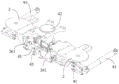
as shown in fig. 24, a damper integration seat 91 is employed to connect to the outer end portion of the connection seat 2. The shock absorber integrated seat 91 can be formed into a skeleton structure by adopting a 3D printing technology, and has a basic supporting function, so that the weight is reduced. The vertical damper, the anti-hunting damper, and the anti-roll torsion bar described above may be mounted on the damper integration seat 91.
Fig. 24 shows that one end of the anti-hunting damper 93 is connected to the damper integration seat 91, the anti-hunting damper 93 extends in the longitudinal direction, and the other end thereof is connected to the vehicle body. Anti-roll damper 93 is used on a faster vehicle to dampen roll motion of the vehicle.
As shown in fig. 1 and 5, the vertical damper 94 extends in the vertical direction, and has a bottom end connected to the damper integration seat 91 and a top end connected to the vehicle body. The vertical damper 94 is used to dampen vertical forces between the truck and the vehicle body.
The anti-roll torsion bar 95 is connected to the damper integration seat 91, including a laterally extending portion and a vertically extending portion, wherein the top of the vertically extending portion interfaces with the vehicle body. The anti-roll torsion bar 95 is used to prevent the vehicle body from excessively tilting, thereby improving comfort and preventing the vehicle from rollover.
Fig. 31 is a schematic structural view of a side member in another bogie provided in an embodiment of the present application, fig. 32 is a schematic structural view of a connecting seat in another bogie provided in an embodiment of the present application, and fig. 33 is an exploded view of an assembly of a side member in another bogie and a connecting seat provided in an embodiment of the present application. As shown in fig. 31 to 33, the top of the connection base 2 is provided with a first side beam mounting boss 29, the surface of the first side beam mounting boss 29 is a plane, the planar shape is a rectangle, and the long side of the rectangle is parallel to the longitudinal direction. The middle portion of the side member 1 is provided on the first side member mounting boss 29. The first side sill mounting boss 29 is used to adjust the height of the side sill 1 to meet the side sill height requirements. The two fixing bases 22 are arranged at intervals in the longitudinal direction, and the two transverse ends of the fixing bases 22 are fixed to the connecting base 2 through bolts.
Fig. 34 is a schematic structural view of another bogie side sill and primary suspension assembly according to an embodiment of the present application, fig. 35 is a cross-sectional view of another bogie side sill and primary suspension assembly according to an embodiment of the present application, and fig. 36 is an exploded view of another bogie side sill and primary suspension assembly according to an embodiment of the present application. As shown in fig. 34 to 36, four one-fastening members 56 are provided in order in the longitudinal direction, and two one-fastening members 56 on the outer side are connected to the lifting member 55 and two one-fastening members 56 on the inner side are connected to the one-fastening hanging device 5. The top of the axle box 33 extends in the longitudinal direction to form a lifting edge 332, and a lifting hook is provided at the lower part of the lifting member 55 and is engaged under the lifting edge 332. In this embodiment, the lifting member 55 has a T-shaped structure, the top of which is connected to a fastening assembly 56, and the bottom of which has a hook-shaped structure, which is hooked under the lifting edge 332.
The embodiment provides a railway vehicle, and the bogie is adopted. The rail vehicle can be an internal combustion locomotive or an electric locomotive, and can be a motor train unit, a subway, a light rail or a tramcar, etc. The railway vehicle provided by the embodiment has the same technical effects as the bogie.
Claims (9)
1. A bogie with side beam mounts, comprising:
two side beams arranged side by side; the side beam comprises an upper side beam plate and a lower side beam plate which are stacked, the upper side beam plate is contacted with the middle part of the lower side beam plate, and a gap is reserved between the end parts;
a transverse connection for connecting the two side beams; the transverse connecting device is positioned below the two side beams;
the fixing seats are arranged above the side beams in a crossing manner, and the two transverse ends of the fixing seats extend downwards from the two sides of the side beams to be connected with the transverse connecting devices;
the safety stop spans over the end part of the side beam, and the two transverse ends of the safety stop extend downwards from the two sides of the side beam to be connected with the primary suspension device; the safety stop includes:
the first stop frame is positioned between the upper side beam plate and the lower side beam plate and spans over the lower side beam plate;
the two transverse ends of the first stop frame extend downwards from the two sides of the lower side beam plate to a series of hanging devices; the primary suspension device is arranged between the wheel set axle box and the side beam of the bogie;
a second stopper frame crossing over the upper side beam plate; the lateral ends of the second stopper frame extend downward from both sides of the upper side rail plate to the first stopper frame.
2. The bogie of claim 1, wherein the anchor block comprises:
a fixed top plate extending in a direction parallel to the side members;
the fixed side plates are vertically arranged at two transverse ends of the fixed top plate;
the fixing bolts sequentially penetrate through bolt holes formed in the fixing top plate and the fixing side plates and then are connected to the transverse connecting device.
3. A bogie according to claim 2 wherein the top of the transverse connection is provided with a first side beam mounting groove extending in the longitudinal direction, the middle of the side beam being received in the first side beam mounting groove; the depth of the first side beam mounting groove is smaller than the thickness of the middle part of the side beam.
4. A bogie as claimed in claim 3 in which the side beams are made of a composite fibre material;
the bogie further comprises: a first upper liner and a first lower liner; the first upper lining piece is arranged between the fixed top plate and the side beam; the first lower lining piece is arranged between the first side beam mounting groove and the middle part of the side beam.
5. The bogie of claim 4, wherein the first underslung comprises:
the first lower substrate plate is arranged in parallel with the bottom surface of the first side beam mounting groove;
two first lower lining side plates which are vertically arranged at two transverse edges of the first lower lining bottom plate; the first side lining plate has a height greater than the depth of the first side beam mounting groove.
6. The bogie of claim 4, wherein the first upper lining comprises:
the first upper substrate plate is arranged in parallel with the lower surface of the fixed top plate;
the two first upper lining side plates are vertically arranged at two transverse edges of the first upper lining bottom plate.
7. A bogie as claimed in claim 3 in which the upper side beam plate has a central thickness greater than end thicknesses; the upper surface of the upper side beam plate is a plane, and the middle part and the end part of the lower surface are smoothly transited through curves;
the thickness of the middle part of the lower side beam plate is larger than that of the end part; the upper surface of the lower side beam plate is a plane, and the middle part and the end part of the lower surface are in smooth transition through curves.
8. The bogie of claim 4, wherein the side beams are made of carbon fiber material.
9. A rail vehicle, comprising: a bogie as claimed in any one of claims 1 to 8.
Priority Applications (2)
| Application Number | Priority Date | Filing Date | Title |
|---|---|---|---|
| CN202111402596.4A CN114084189B (en) | 2021-11-24 | 2021-11-24 | Bogie with side beam fixing seat and railway vehicle |
| PCT/CN2022/134008 WO2023093801A1 (en) | 2021-11-24 | 2022-11-24 | Bogie with side beam fixing seat, and rail vehicle |
Applications Claiming Priority (1)
| Application Number | Priority Date | Filing Date | Title |
|---|---|---|---|
| CN202111402596.4A CN114084189B (en) | 2021-11-24 | 2021-11-24 | Bogie with side beam fixing seat and railway vehicle |
Publications (2)
| Publication Number | Publication Date |
|---|---|
| CN114084189A CN114084189A (en) | 2022-02-25 |
| CN114084189B true CN114084189B (en) | 2023-04-28 |
Family
ID=80303930
Family Applications (1)
| Application Number | Title | Priority Date | Filing Date |
|---|---|---|---|
| CN202111402596.4A Active CN114084189B (en) | 2021-11-24 | 2021-11-24 | Bogie with side beam fixing seat and railway vehicle |
Country Status (2)
| Country | Link |
|---|---|
| CN (1) | CN114084189B (en) |
| WO (1) | WO2023093801A1 (en) |
Families Citing this family (2)
| Publication number | Priority date | Publication date | Assignee | Title |
|---|---|---|---|---|
| CN114084189B (en) * | 2021-11-24 | 2023-04-28 | 中车唐山机车车辆有限公司 | Bogie with side beam fixing seat and railway vehicle |
| CN114084190B (en) * | 2021-11-24 | 2023-05-23 | 中车唐山机车车辆有限公司 | Single-layer side beam bogie and railway vehicle |
Family Cites Families (11)
| Publication number | Priority date | Publication date | Assignee | Title |
|---|---|---|---|---|
| EP2660120B1 (en) * | 2012-05-03 | 2017-06-28 | CRRC Shandong Co., Ltd. | Railway vehicle bogie |
| CN203753157U (en) * | 2014-04-02 | 2014-08-06 | 成都市新筑路桥机械股份有限公司 | Secondary sandglass spring suspension device for 100% low floor tramcar |
| CN103879425B (en) * | 2014-04-02 | 2016-09-07 | 成都市新筑路桥机械股份有限公司 | A kind of non-powered bogie for 100% low floor vehicle |
| JP2016068642A (en) * | 2014-09-26 | 2016-05-09 | ヤマハ発動機株式会社 | vehicle |
| JP6697352B2 (en) * | 2016-08-22 | 2020-05-20 | 川崎重工業株式会社 | Railcar bogie |
| CN112644549B (en) * | 2019-10-10 | 2022-06-14 | 中车唐山机车车辆有限公司 | Bogie and rail vehicle |
| CN112519825B (en) * | 2020-12-09 | 2022-04-15 | 中车唐山机车车辆有限公司 | Bogie and rail vehicle |
| CN112550340B (en) * | 2020-12-09 | 2022-05-17 | 中车唐山机车车辆有限公司 | Bogie and rail vehicle |
| CN112519827B (en) * | 2020-12-09 | 2022-07-26 | 中车唐山机车车辆有限公司 | Bogie crossbeam, bogie and rail vehicle |
| CN112519826B (en) * | 2020-12-09 | 2022-05-17 | 中车唐山机车车辆有限公司 | Bogie and rail vehicle |
| CN114084189B (en) * | 2021-11-24 | 2023-04-28 | 中车唐山机车车辆有限公司 | Bogie with side beam fixing seat and railway vehicle |
-
2021
- 2021-11-24 CN CN202111402596.4A patent/CN114084189B/en active Active
-
2022
- 2022-11-24 WO PCT/CN2022/134008 patent/WO2023093801A1/en unknown
Also Published As
| Publication number | Publication date |
|---|---|
| WO2023093801A1 (en) | 2023-06-01 |
| CN114084189A (en) | 2022-02-25 |
Similar Documents
| Publication | Publication Date | Title |
|---|---|---|
| CN112550340B (en) | Bogie and rail vehicle | |
| CN112519820B (en) | Bogie system of railway vehicle and railway vehicle | |
| CN114084189B (en) | Bogie with side beam fixing seat and railway vehicle | |
| CN114084186B (en) | Bogie and rail vehicle | |
| CN112519821B (en) | Bogie cabin for railway vehicle and bogie system | |
| CN114084187B (en) | Double-deck curb girder bogie and rail vehicle | |
| CN109878545B (en) | Tramcar and bogie | |
| WO2022120933A1 (en) | Bogie beam, bogie and rail vehicle | |
| CN111348067B (en) | Bogie and rail vehicle | |
| CN112644542B (en) | Steering frame | |
| CN114084188B (en) | Bogie with connecting seat and railway vehicle | |
| CN112519826A (en) | Bogie and rail vehicle | |
| CN114084185B (en) | Bogie with safety stop and railway vehicle | |
| CN114084190B (en) | Single-layer side beam bogie and railway vehicle | |
| WO2022120966A1 (en) | Bogie side beam, bogie, and railway vehicle | |
| CN110588700B (en) | Locomotive bogie | |
| CN217575202U (en) | Large-axle-weight multipurpose bogie and railway vehicle | |
| CN217623574U (en) | Electrically-driven bogie and railway engineering vehicle | |
| CN219382481U (en) | Framework, triaxial bogie and railway wagon | |
| CN211685111U (en) | Axle box cross connection type express freight car bogie | |
| CN211893233U (en) | Bogie frame of railway vehicle | |
| CN210760784U (en) | Built-in bogie frame of axle box | |
| CN116061983A (en) | Light rail vehicle motor car bogie and light rail vehicle | |
| CN117962942A (en) | Bogie and rail vehicle | |
| CN114523994A (en) | Electrically-driven bogie and railway engineering vehicle |
Legal Events
| Date | Code | Title | Description |
|---|---|---|---|
| PB01 | Publication | ||
| PB01 | Publication | ||
| SE01 | Entry into force of request for substantive examination | ||
| SE01 | Entry into force of request for substantive examination | ||
| GR01 | Patent grant | ||
| GR01 | Patent grant |