CN112550340B - Bogie and rail vehicle - Google Patents
Bogie and rail vehicle Download PDFInfo
- Publication number
- CN112550340B CN112550340B CN202011429611.XA CN202011429611A CN112550340B CN 112550340 B CN112550340 B CN 112550340B CN 202011429611 A CN202011429611 A CN 202011429611A CN 112550340 B CN112550340 B CN 112550340B
- Authority
- CN
- China
- Prior art keywords
- mounting
- bogie
- plate
- main
- main body
- Prior art date
- Legal status (The legal status is an assumption and is not a legal conclusion. Google has not performed a legal analysis and makes no representation as to the accuracy of the status listed.)
- Active
Links
Images


Classifications
-
- B—PERFORMING OPERATIONS; TRANSPORTING
- B61—RAILWAYS
- B61F—RAIL VEHICLE SUSPENSIONS, e.g. UNDERFRAMES, BOGIES OR ARRANGEMENTS OF WHEEL AXLES; RAIL VEHICLES FOR USE ON TRACKS OF DIFFERENT WIDTH; PREVENTING DERAILING OF RAIL VEHICLES; WHEEL GUARDS, OBSTRUCTION REMOVERS OR THE LIKE FOR RAIL VEHICLES
- B61F5/00—Constructional details of bogies; Connections between bogies and vehicle underframes; Arrangements or devices for adjusting or allowing self-adjustment of wheel axles or bogies when rounding curves
- B61F5/50—Other details
- B61F5/52—Bogie frames
-
- B—PERFORMING OPERATIONS; TRANSPORTING
- B61—RAILWAYS
- B61F—RAIL VEHICLE SUSPENSIONS, e.g. UNDERFRAMES, BOGIES OR ARRANGEMENTS OF WHEEL AXLES; RAIL VEHICLES FOR USE ON TRACKS OF DIFFERENT WIDTH; PREVENTING DERAILING OF RAIL VEHICLES; WHEEL GUARDS, OBSTRUCTION REMOVERS OR THE LIKE FOR RAIL VEHICLES
- B61F15/00—Axle-boxes
- B61F15/20—Details
-
- B—PERFORMING OPERATIONS; TRANSPORTING
- B61—RAILWAYS
- B61F—RAIL VEHICLE SUSPENSIONS, e.g. UNDERFRAMES, BOGIES OR ARRANGEMENTS OF WHEEL AXLES; RAIL VEHICLES FOR USE ON TRACKS OF DIFFERENT WIDTH; PREVENTING DERAILING OF RAIL VEHICLES; WHEEL GUARDS, OBSTRUCTION REMOVERS OR THE LIKE FOR RAIL VEHICLES
- B61F5/00—Constructional details of bogies; Connections between bogies and vehicle underframes; Arrangements or devices for adjusting or allowing self-adjustment of wheel axles or bogies when rounding curves
- B61F5/02—Arrangements permitting limited transverse relative movements between vehicle underframe or bolster and bogie; Connections between underframes and bogies
- B61F5/04—Bolster supports or mountings
- B61F5/10—Bolster supports or mountings incorporating fluid springs
-
- B—PERFORMING OPERATIONS; TRANSPORTING
- B61—RAILWAYS
- B61F—RAIL VEHICLE SUSPENSIONS, e.g. UNDERFRAMES, BOGIES OR ARRANGEMENTS OF WHEEL AXLES; RAIL VEHICLES FOR USE ON TRACKS OF DIFFERENT WIDTH; PREVENTING DERAILING OF RAIL VEHICLES; WHEEL GUARDS, OBSTRUCTION REMOVERS OR THE LIKE FOR RAIL VEHICLES
- B61F5/00—Constructional details of bogies; Connections between bogies and vehicle underframes; Arrangements or devices for adjusting or allowing self-adjustment of wheel axles or bogies when rounding curves
- B61F5/02—Arrangements permitting limited transverse relative movements between vehicle underframe or bolster and bogie; Connections between underframes and bogies
- B61F5/04—Bolster supports or mountings
- B61F5/12—Bolster supports or mountings incorporating dampers
-
- B—PERFORMING OPERATIONS; TRANSPORTING
- B61—RAILWAYS
- B61F—RAIL VEHICLE SUSPENSIONS, e.g. UNDERFRAMES, BOGIES OR ARRANGEMENTS OF WHEEL AXLES; RAIL VEHICLES FOR USE ON TRACKS OF DIFFERENT WIDTH; PREVENTING DERAILING OF RAIL VEHICLES; WHEEL GUARDS, OBSTRUCTION REMOVERS OR THE LIKE FOR RAIL VEHICLES
- B61F5/00—Constructional details of bogies; Connections between bogies and vehicle underframes; Arrangements or devices for adjusting or allowing self-adjustment of wheel axles or bogies when rounding curves
- B61F5/02—Arrangements permitting limited transverse relative movements between vehicle underframe or bolster and bogie; Connections between underframes and bogies
- B61F5/22—Guiding of the vehicle underframes with respect to the bogies
-
- B—PERFORMING OPERATIONS; TRANSPORTING
- B61—RAILWAYS
- B61F—RAIL VEHICLE SUSPENSIONS, e.g. UNDERFRAMES, BOGIES OR ARRANGEMENTS OF WHEEL AXLES; RAIL VEHICLES FOR USE ON TRACKS OF DIFFERENT WIDTH; PREVENTING DERAILING OF RAIL VEHICLES; WHEEL GUARDS, OBSTRUCTION REMOVERS OR THE LIKE FOR RAIL VEHICLES
- B61F5/00—Constructional details of bogies; Connections between bogies and vehicle underframes; Arrangements or devices for adjusting or allowing self-adjustment of wheel axles or bogies when rounding curves
- B61F5/26—Mounting or securing axle-boxes in vehicle or bogie underframes
- B61F5/30—Axle-boxes mounted for movement under spring control in vehicle or bogie underframes
- B61F5/305—Axle-boxes mounted for movement under spring control in vehicle or bogie underframes incorporating rubber springs
-
- Y—GENERAL TAGGING OF NEW TECHNOLOGICAL DEVELOPMENTS; GENERAL TAGGING OF CROSS-SECTIONAL TECHNOLOGIES SPANNING OVER SEVERAL SECTIONS OF THE IPC; TECHNICAL SUBJECTS COVERED BY FORMER USPC CROSS-REFERENCE ART COLLECTIONS [XRACs] AND DIGESTS
- Y02—TECHNOLOGIES OR APPLICATIONS FOR MITIGATION OR ADAPTATION AGAINST CLIMATE CHANGE
- Y02T—CLIMATE CHANGE MITIGATION TECHNOLOGIES RELATED TO TRANSPORTATION
- Y02T30/00—Transportation of goods or passengers via railways, e.g. energy recovery or reducing air resistance
Abstract
The embodiment of the application provides a bogie and rail vehicle, wherein, the bogie includes: the cross beam extends along the transverse direction and comprises two cross beam single bodies which are symmetrically arranged and connected with each other, and a traction device installation space is formed between the two cross beam single bodies; the secondary suspension mounting seat is arranged on the top surface of the cross beam, and a mounting channel which is longitudinally communicated is formed between the secondary suspension mounting seat and the cross beam; a side member extending in a longitudinal direction; the number of the side beams is two, and the two side beams are arranged side by side and respectively penetrate through one installation channel; the wheel sets are symmetrically arranged below the side beams; a suspension device disposed between the side member and the axle box; the secondary suspension device is arranged on the secondary suspension mounting seat; the bottom end of the traction device is inserted into the traction device installation space between the two cross beam single bodies; and the braking device is arranged on the cross beam and is used for applying braking operation to the wheels. The bogie and the rail vehicle provided by the embodiment of the application have the advantages of easiness in assembly and easiness in maintenance.
Description
Technical Field
The application relates to a rail vehicle walking technology, in particular to a bogie and a rail vehicle.
Background
The rail vehicle is an important traffic tie connecting cities, is gradually a main vehicle in the cities, and is also a main carrier for realizing goods transportation. The rail vehicle mainly includes: the bogie is used for bearing the vehicle body and realizing walking and steering functions.
The bogie comprises a framework, wheel pairs, a traction device, a buffer device and other structures, wherein the framework comprises two side beams extending along the vehicle length direction and a cross beam connecting the two side beams, and the connection modes between the cross beam and the side beams are various. After studying various forms of bogies, the skilled person has found that conventional bogies have some technical drawbacks, such as: the self weight is large, so that the acting force of the wheel pair is large, the abrasion of the wheel rail is large, and large noise is generated; the frame is rigidly connected, so that the damping capacity is poor, the carriage vibration is large, and the riding comfort is poor; the wheel load reduction rate is high, and the safety is reduced; the problem that the carriage is prone to side turning due to poor anti-side rolling capacity is solved, the carriage is greatly vibrated due to insufficient vertical buffering capacity, the riding comfort is poor, the traction efficiency is low due to large dead weight, and the assembly efficiency is low due to unreasonable component mounting layout.
Disclosure of Invention
In order to solve one of the technical defects, the embodiment of the application provides a bogie and a railway vehicle.
An embodiment of a first aspect of the present application provides a bogie, including:
a cross member extending in a transverse direction; the cross beam comprises two cross beam single bodies which are symmetrically arranged and connected with each other, and a traction device installation space is formed between the two cross beam single bodies;
the secondary suspension mounting seats are two in number and are symmetrically arranged on the top surface of the cross beam; a longitudinally through mounting channel is formed between the secondary suspension mounting seat and the cross beam; the longitudinal direction and the transverse direction are two horizontal directions which are vertical to each other;
a side member extending in a longitudinal direction; the number of the side beams is two, the two side beams are arranged side by side and respectively penetrate through one installation channel;
the wheel sets are symmetrically arranged below the side beams; the wheel pair comprises an axle, wheels symmetrically arranged on the axle and axle boxes symmetrically arranged on the axle;
a suspension device disposed between the side member and the axle box;
the secondary suspension device is arranged on the secondary suspension mounting seat;
the bottom end of the traction device is inserted into the traction device installation space between the two cross beam single bodies;
and the braking device is arranged on the cross beam and is used for applying braking operation to the wheels.
An embodiment of a second aspect of the present application provides a rail vehicle, including: a bogie as described above.
The bogie provided by the embodiment of the application adopts the transverse beam extending along the transverse direction, the transverse beam comprises two transverse beam single bodies which are symmetrically arranged and mutually connected, and a traction device installation space is formed between the two transverse beam single bodies; the secondary suspension mounting seat is arranged on the top surface of the cross beam, and a mounting channel which is longitudinally communicated is formed between the secondary suspension mounting seat and the cross beam; the side beam extends along the longitudinal direction and penetrates through the installation channel; the wheel sets are symmetrically arranged below the side beams; a series of suspension devices are arranged between the side beams and the axle boxes; the secondary suspension device is arranged on the secondary suspension mounting seat; the bottom end of the traction device is inserted into the traction device installation space between the two cross beam single bodies; and the braking device is arranged on the cross beam and is used for applying braking operation to the wheels, and the weight load of the vehicle body is transferred to the wheel pair through the secondary suspension device, the secondary suspension mounting seat and the side beam. The structure inequality of the bogie that this embodiment provided and arbitrary bogie of tradition compares in the integrative structure of traditional crossbeam and curb girder, and crossbeam, the curb girder that this embodiment provided are the independent structure, and the volume is less, and easily production, transportation and assembly can improve assembly efficiency.
Drawings
The accompanying drawings, which are included to provide a further understanding of the application and are incorporated in and constitute a part of this application, illustrate embodiment(s) of the application and together with the description serve to explain the application and not to limit the application. In the drawings:
fig. 1 is a perspective view of a bogie provided in an embodiment of the present application;
FIG. 2 is a schematic structural view of a cross beam, a side beam and a secondary suspension mount of the bogie according to the embodiment of the present invention;
FIG. 3 is a perspective view of a beam provided in an embodiment of the present application;
fig. 4 is a perspective view of a single cross beam provided in an embodiment of the present application;
FIG. 5 is a cross-sectional view of a beam provided by an embodiment of the present application;
FIG. 6 is an enlarged view of a portion of area A of FIG. 5;
fig. 7 is an exploded view of two cross beam units connected according to the embodiment of the present application;
FIG. 8 is a perspective view of a side sill provided by an embodiment of the present application;
FIG. 9 is a front view of a side sill provided in an embodiment of the present application;
FIG. 10 is another front view of the side rail provided by the present application;
FIG. 11 is a schematic view of the side sill provided in this embodiment under a first vertical load;
FIG. 12 is a schematic view of the side sill of the present embodiment receiving a second vertical load;
FIG. 13 is an exploded view of a cross member, side members and secondary suspension mounts of the truck according to an embodiment of the present application;
FIG. 14 is a top perspective view of a secondary suspension mount provided in accordance with an embodiment of the present application;
FIG. 15 is a bottom perspective view of a secondary suspension mount provided in accordance with an embodiment of the present application;
FIG. 16 is a partial cross-sectional view of the secondary suspension mount assembly provided in accordance with an embodiment of the present application assembled with side and cross members;
fig. 17 is a schematic structural diagram of a bogie provided with a secondary suspension device according to an embodiment of the present application;
fig. 18 is a schematic structural diagram of a wheel pair in a bogie provided by an embodiment of the present application;
FIG. 19 is a partial schematic view of a bogie provided with a safety stop according to an embodiment of the present application;
FIG. 20 is a cross-sectional view of a truck provided with a safety stop according to an embodiment of the present application;
FIG. 21 is a schematic structural view of a safety stop device according to an embodiment of the present disclosure;
FIG. 22 is an exploded view of the safety stop device, a suspension system and axle housing assembly provided by embodiments of the present application;
FIG. 23 is a perspective view of a brake hanger in a truck according to an embodiment of the present application;
FIG. 24 is a schematic view of the connection of the brake spider to the cross-member as provided by an embodiment of the present application;
FIG. 25 is an exploded view of the brake spider and cross member connection provided by an embodiment of the present application;
FIG. 26 is a cross-sectional view of the brake spider and cross-member connection provided in accordance with an embodiment of the present application;
FIG. 27 is a schematic perspective view of a beam coupled to a vertical shock absorber according to an embodiment of the present application;
FIG. 28 is an enlarged view of area B of FIG. 27;
FIG. 29 is an exploded view of the attachment of the cross beam to the vertical shock absorber provided in accordance with an embodiment of the present application;
FIG. 30 is a schematic view of the disposition of a vertical shock absorber on a bogie according to an embodiment of the present invention;
FIG. 31 is a perspective view of an anti-roll torsion bar provided in accordance with an embodiment of the present application;
FIG. 32 is a schematic view of a cross-member coupled to an axle housing via a single tension rod according to an exemplary embodiment of the present disclosure;
FIG. 33 is a schematic perspective view of the connection of the towing pintle, the longitudinal stop and the cross member provided in the embodiments of the present application;
FIG. 34 is a cross-sectional view of the pulling core pin, longitudinal stop and cross member attachment provided in accordance with an embodiment of the present application;
FIG. 35 is a schematic perspective view of a pull core pin, longitudinal stop connection provided in accordance with an embodiment of the present application;
FIG. 36 is a schematic structural view of a pulling core pin according to an embodiment of the present application;
FIG. 37 is an exploded view of a kingpin provided in accordance with an embodiment of the present application;
FIG. 38 is a schematic perspective view of a tow kingpin, cross member connection provided in accordance with an embodiment of the present application;
FIG. 39 is a schematic perspective view of a kingpin attached to a cross-damper in accordance with an exemplary embodiment of the present disclosure;
FIG. 40 is a front view of the attachment of the kingpin to a transverse damper provided in accordance with an embodiment of the present application;
FIG. 41 is an enlarged view of area C of FIG. 40;
FIG. 42 is a cross-sectional view of the attachment of the kingpin to a transverse damper provided in accordance with an embodiment of the present application;
fig. 43 is an enlarged schematic view of region D in fig. 42.
Fig. 44 is a perspective view of a power bogie provided in an embodiment of the present application.
Fig. 45 is a schematic connection diagram of a direct drive motor and an axle provided in the embodiment of the present application;
FIG. 46 is a schematic cross-sectional view of a direct drive motor and an axle provided in accordance with an embodiment of the present application;
FIG. 47 is an enlarged partial view of portion E of FIG. 46;
fig. 48 is a schematic perspective view of a balancing rod of a motor according to an embodiment of the present disclosure;
fig. 49 is a cross-sectional view of a connection between a rod body and a node of a motor balance rod provided in an embodiment of the present application;
fig. 50 is an exploded view of a motor stabilizer bar according to an embodiment of the present application;
FIG. 51 is a schematic structural diagram of a secondary suspension mount provided in an embodiment of the present application connected to a traction motor via a motor balancing bar;
FIG. 52 is a schematic illustration of a truck bay and truck mounting of a railway vehicle according to an embodiment of the present application;
FIG. 53 is a schematic view of the truck bay shown in FIG. 52;
FIG. 54 is an exploded schematic view of the main deck and side deck boards of the truck cabin shown in FIG. 53;
FIG. 55 is an exploded view of the connecting structure of the main deck panel and the side deck panels shown in FIG. 54;
FIG. 56 is an assembled view of the connecting structure of the main deck board and the side deck boards shown in FIG. 55;
FIG. 57 is a schematic view of the anti-rotation mount of the truck bay shown in FIG. 54;
FIG. 58 is an enlarged partial view of the truck bay shown in FIG. 53;
FIG. 59 is an enlarged partial view of the truck bay of FIG. 58;
FIG. 60 is an exploded schematic view of the side deck panel and the first link of the truck bay shown in FIG. 53;
FIG. 61 is an exploded view of the connection structure of the side deck panel shown in FIG. 59 with the first and second connection frames;
FIG. 62 is an exploded view of the connection of the side deck connection link of the first link and a set of spring mounts of the bogie;
FIG. 63 is an exploded view of the connection of the brake shoe connecting rod of the second link carriage and the brake unit shoe of the truck;
FIG. 64 is an exploded view of the connection of the beam connecting rod of the second link frame and the beam of the bogie;
FIG. 65 is a perspective view of a first link of the truck bay of FIG. 53;
fig. 66 is a perspective view of a second link of the truck bay of fig. 54.
Reference numerals:
1-a side beam; 11-main side beam panels; 111-the middle section of the mainboard; 112-main plate transition section; 113-a motherboard connecting section; 12-auxiliary side beam plate; 121-middle section of auxiliary board; 122-auxiliary plate transition section; 123-auxiliary board connecting section; 13-elastic stop; 14-a buffer gap; 15-first side rail locating pin; 16-a second side beam locating pin; 17-third side rail locating pin; 18-positioning the metal piece;
2-a cross beam; 21-a beam body; 210-a first pin hole; 211-side beam alignment pin holes; 212-a second series mounting table; 2121-series bolt holes; 2122-two series of positioning holes; 213-brake bolt hole; 214-vertical shock absorber mounting ears; 215-anti-roll torsion bar mounting; 216-anti-hunting damper mounting plate; 217-single pull rod connection; 218-center pin connection; 219-nameplate mounting portion; 22-beam connecting arm; 23-beam connecting pin; 24-beam connection flange; 25-beam connection node; 26-beam connection gasket; 27-beam mounting ring; 28-beam connecting bolts;
31-axle; 32-a wheel; 33-axle boxes; 331-a series of positioning holes; 332-a limit notch; 333-sealing bearing;
4-a series of suspension devices; 41-a series of suspension mounting seats; 411-lower mount; 412-upper mount; 42-primary suspension; 43-lifting by wheel set; 431-limit stop boss; 432-linker arm; 441-lower backing plate; 442-upper backing plate;
5-safety stop means; 51-safety stop seat; 52-safety stop;
6-pulling the center pin; 61-a center pin body; 61 a-a stop contact zone; 61 b-mating holes; 62-mounting arm 63-limiting surface; 64-lifting and hanging piece; 641-lifting the mounting body; 642-lifting the stop block; 643-a second trim pad; 65-longitudinal stop; 651-first spacer; 652-a stopper body; 653-mounting flange; 654-stop fixing bolt;
7-braking hanging seat; 71-brake beam attachment holes; 72-brake beam connecting bolt; 73-brake shoe pads; 74-brake mounting holes; 75-cabin mounting holes;
8-secondary suspension mounting seats; 81-mounting a base top plate; 82-mount side plate; 83-mount connection; 84-mount bolt holes; 85-mounting seat positioning protrusions; 86-side beam positioning counter bores; 871-lower transition plate; 872-upper transition plate; 88-secondary mounting portion; 89-a motor mounting part; 810-air spring;
91-a traction motor; 911-a stator; 912-end cap; 912 a-gullet; 913-a rotor; 92-motor balancing pole; 921-rod body; 922-node; 923-a metal retainer ring; 923 a-a positioning boss; 923 b-a card slot; 924-a spring collar; 925-dustproof check ring; 926-mounting the main body; 927-extension ring; 928-annular seal teeth; 93-vertical vibration absorber; 94-a first fixing bolt; 941 — first bolt head; 942 — a first side plane; 943-first screw; 944 — a first trim shim; 945-first nut; 95-anti-roll torsion bar; 951-transverse torsion bar; 952-a vertical torsion bar; 953-torsion bar node; 954-torsion bar mounting; 96-anti-snake shock absorber; 97-single pull rod; 971-a drawbar node; 98-transverse damper; 99-a second fixing bolt; 991-second bolt head; 992-second side plane; 993-a second screw; 994-a third adjustment pad; 995-a second nut;
101-a bogie; 102-a bogie cabin; 1021-main deck board, 10211-main deck board through hole, 10212-main deck board mounting seat body; 10213-deck connection rod mount; 1022-side deck boards; 10221-side deck via; 10222-anti-rotation boss; 1023-sound absorbing panel; 1024 — a first anti-rotation bolt; 10241-first anti-rotation platform; 10251-first anti-rotation nut; 1026-prevent the swivel mount, 10261-prevent the rotary convex line, 10262-prevent the rotary groove, 1027-prevent the rotary shell fragment; 1031-first connecting rack; 10311-side deck connection bar; 10311 a-a fixed seat interface; 10312-main deck connecting rod; 10313-first connecting frame reinforcing rod; 1032-a second connecting frame; 10321-brake shoe connecting rod; 10321 a-brake shoe interface; 10322-beam connecting rod; 10322 a-beam interface; 10323-a second link reinforcing bar; 1033-anti-rotation recesses; 1034-a second anti-rotation bolt; 10341-a second tamper proof station; 10351 — a second anti-rotation nut; 1036-a second anti-rotation shrapnel; 1041-fixing bolt; 1042-a fixing nut; 1043-a gasket; 1044-rubber node.
Detailed Description
The embodiment provides a bogie which can be applied to a railway vehicle and is arranged below a carriage of the railway vehicle. The rail vehicle can be a diesel locomotive or an electric locomotive, can be a motor train unit, a subway, a light rail or a tramcar and the like, and can be a passenger vehicle or a freight vehicle. In the present embodiment, the longitudinal direction of the vehicle compartment is referred to as the longitudinal direction, the width direction of the vehicle compartment is referred to as the lateral direction, and the vertical direction is referred to as the vertical direction or the vertical direction.
Fig. 1 is a perspective view of a bogie provided in an embodiment of the present application, and fig. 2 is a schematic structural view of a cross beam, a side beam, and a secondary suspension mount in the bogie provided in the embodiment of the present application. As shown in fig. 1 and 2, the present embodiment provides a bogie including: the device comprises side beams 1, cross beams 2, wheel sets 3, a primary suspension device 4, a secondary suspension mounting seat 8, a secondary suspension device, a traction device and a braking device.
Wherein the cross beam 2 extends in the transverse direction. The crossbeam 2 includes two crossbeam monomers that the symmetry set up and interconnect, is formed with draw gear installation space between two crossbeam monomers. The secondary suspension mounting seats 8 are two in number and symmetrically arranged on the top surface of the cross beam 3, and a longitudinally through mounting channel is formed between the secondary suspension mounting seats 8 and the cross beam 2. The side beams 1 extend longitudinally, the number of the side beams is two, and the two side beams 1 are arranged side by side and respectively penetrate through an installation channel.
The wheel sets 3 are symmetrically arranged below the side beams 1, and each wheel set comprises an axle, wheels symmetrically arranged on the axle and axle boxes symmetrically arranged on the axle. A suspension 4 is provided between the side members 1 and the axle boxes for damping vertical forces between the side members 1 and the wheel sets 3. The secondary suspension device is arranged on the secondary suspension mounting seat 8, and the top of the secondary suspension device is connected with the bottom of the carriage and used for buffering vertical force between the carriage and the bogie.
The bottom end of the traction device is inserted into the traction device installation space between the two cross beam single bodies, and the top end of the traction device is connected with the bottom of the carriage and used for transmitting longitudinal traction force or braking force between the carriage and the bogie. A brake device is provided on the cross member 2 for applying a braking operation to the wheel.
The bogie provided by the embodiment adopts the transverse beam extending along the transverse direction, the transverse beam comprises two transverse beam single bodies which are symmetrically arranged and connected with each other, and a traction device installation space is formed between the two transverse beam single bodies; the secondary suspension mounting seat is arranged on the top surface of the cross beam, and a mounting channel which is longitudinally communicated is formed between the secondary suspension mounting seat and the cross beam; the side beam extends along the longitudinal direction and penetrates through the installation channel; the wheel sets are symmetrically arranged below the side beams; a series of suspension devices are arranged between the side beams and the axle boxes; the secondary suspension device is arranged on the secondary suspension mounting seat; the bottom end of the traction device is inserted into the traction device installation space between the two cross beam single bodies; and the braking device is arranged on the cross beam and is used for applying braking operation to the wheels, and the weight load of the vehicle body is transferred to the wheel pair through the secondary suspension device, the secondary suspension mounting seat and the side beam. The structure of the bogie that this embodiment provided is all inequality with any bogie of tradition, compares in the integrative structure of traditional crossbeam and curb girder, and crossbeam, the curb girder that this embodiment provided are independent structure, and the volume is less, easily production, transportation and assembly, can improve assembly efficiency.
On the basis of the above technical solution, the embodiment provides a concrete implementation manner of a bogie: fig. 3 is a perspective view of a cross beam provided in an embodiment of the present application, and fig. 4 is a perspective view of a cross beam unit provided in an embodiment of the present application. As shown in fig. 3 and 4, the cross member 2 includes: the two cross beam single bodies are sequentially arranged along the transverse direction and are mutually connected to form the cross beam.
The crossbeam monomer includes: a beam main body 21 and a beam connecting arm 22, both extending in the lateral direction. The inner end face of the beam main body 21 facing the other beam main body 21 has a first mounting region and a second mounting region. One end of the beam connecting arm 22 is fixed to a first mounting region and the other end is connected to a second mounting region in another beam cell by a beam connecting means.
The cross member body 21 is assembled with the side member 1 to constitute a frame of the bogie, and serves as a body member of the bogie. Specifically, a side beam mounting interface for assembling with the side beam 1 is arranged on the top surface of the middle part of the cross beam main body 21, and the side beam is positioned above the cross beam main body 21. The beam 2 can be made of cast aluminum alloy or other light-weight materials, and a cast mould can be made by adopting an additive manufacturing technology, so that the weight is reduced.
As shown in fig. 4, the width of the end of the beam main body 21 facing the other beam unit is larger than the width of the middle of the beam main body 21. An end face of the beam main body 21 facing the other beam monomer is called an inner end face, and the first mounting region and the second mounting region are respectively located on the inner end face of the beam main body 21, specifically, are arranged at two ends in the width direction of the inner end face. The first mounting area is spaced from the second mounting area to provide clearance between the two beam connecting arms 22 for receiving a kingpin in a truck hitch. The top of the traction center pin is connected with the vehicle body, and the bottom of the traction center pin is inserted into the gap between the two cross beam connecting arms 22 to transmit traction force or braking force between the cross beams.
The connection between the two cross beam units can be a rigid connection, for example, by connecting the cross beam connecting arm 22 to the other cross beam main body 21 by bolts. Alternatively, the following scheme provided by this embodiment may also be adopted:
one implementation is as follows: the cross beam connecting pin is adopted, and two ends along the axial direction are respectively called a first end and a second end. The first end is connected to the beam connecting arm 22, and the second end is inserted and fixed in the first pin hole formed in the second mounting area. The first end of the beam connecting pin and the beam connecting arm 22 can be connected by bolts, welding, pressing, and the like, and the second end of the beam connecting pin fixed in the second pin hole can be connected by welding, pressing, or bolts through a gasket.
The other realization mode is as follows: fig. 5 is a cross-sectional view of a cross beam provided in an embodiment of the present application, fig. 6 is a partially enlarged view of a region a in fig. 5, and fig. 7 is an exploded view of two cross beam units connected together provided in an embodiment of the present application. As shown in fig. 5 to 7, the beam connecting device includes: beam connecting pins 23, beam connecting flanges 24, beam connecting nodes 25 and beam connecting washers 26.
The beam connection node 25 is an annular structure, and is press-fitted in the first pin hole 210 and fixed to the beam main body 21. In fig. 6, the beam connecting node 25 extends in the left-right direction, and the left end thereof is referred to as a first end and the right end thereof is referred to as a second end.
The second end of the beam connecting pin 23 is press-fitted into the beam connecting node 25 and fixed relative to the beam connecting node 25. A beam connection washer 26 is provided at the second end face of the beam connection pin 23 coaxially with the beam connection pin 23. The outer diameter of the beam connection washer 26 is larger than the inner diameter of the beam connection node 25, and the inner diameter of the beam connection washer 26 is smaller than the outer diameter of the beam connection pin 23. The second end of the beam connecting pin 23 is provided with an internal threaded hole, and a beam connecting bolt 28 is screwed into and fixed to the internal threaded hole of the beam connecting pin 23 after penetrating through the beam connecting washer 26 from the right side, so that the beam connecting pin 23 and the beam connecting node 25 are fixedly connected.
The beam connecting flange 24 has an outer ring and an inner ring, wherein the inner ring is inserted into the first pin hole 210 and abuts against the axial second end of the beam connecting node 25, and the outer ring of the beam connecting flange 24 is connected with the beam main body 21 through a bolt, so that the beam connecting node 25 is fixedly connected with the beam main body 21.
Further, the beam connecting device further comprises: and at least one beam mounting ring 27 disposed in the first pin hole 210 between the left end of the beam connection node 25 and the beam main body 21. During assembly, the beam connection pin 23 is fixed to the beam connection bolt 28 after passing through at least one beam mounting ring 24, the beam connection node 25, and the beam connection washer 26 in this order from the left side. The beam mounting rings 27 are used for adjusting size deviation between the beam connecting node 25 and the beam main body 21, and the number and the thickness of the beam mounting rings 27 can be set according to specific size deviation, so that the beam connecting node 25 can be fixed in the beam main body 21, and vibration caused by relative movement between the beam mounting rings and the beam main body 21 in the vehicle running process is avoided.
The first end of the beam connecting pin 23 is inserted into a second pin hole formed in the end surface of the beam connecting arm 22, and the outer peripheral surface of the beam connecting pin 23 extends radially outward to form a mounting flange connected with a flange provided at the end of the beam connecting arm 22 by a bolt. The radial force between the beam connecting pin 23 and the beam connecting arm 22 is borne by the end of the beam connecting arm 22 inserted into the second pin hole, and the bolt connected with the beam connecting arm 22 is prevented from bearing the shearing force.
The assembly process of the beam connecting device for connecting the beam monomers comprises the following steps: the first end of the beam connecting pin 23 is first bolted to the beam connecting arm 22, and the beam connecting pin 23 is then connected to the beam main body 21. The process of connecting the beam connecting pin 23 with the beam main body 21 is specifically that according to the measured dimensional deviation, a beam mounting ring 27 is firstly installed in a first pin hole 210 of the beam main body 21, the beam connecting node 25 is pressed and installed, then the beam connecting pin 23 is pressed and installed in the beam connecting node 25, a beam connecting gasket 26 is placed, and a beam connecting bolt 28 penetrates through the beam connecting gasket 26 and then is screwed into the beam connecting pin 23 for fixing. Finally, the beam connecting flange 24 is abutted against the right end of the beam connecting node 25 and fixed to the beam main body 21 by bolts. Axial force, radial force, torsional force and deflection deformation between the two cross beam single bodies 2 are borne by the cross beam connecting nodes.
Further, the beam connection node 25 comprises a metal shell, a metal inner ring and a rubber block arranged between the metal shell and the metal inner ring, and the rubber block, the metal shell and the metal inner ring are vulcanized to form an integrated structure, so that the beam connection node 25 has certain deformation capacity. The beam connecting node 25 provided by the embodiment can generate a certain angle deflection between the two beam single bodies 2. For example: when there is the pit in the orbital below of one side, when the bogie passes through this position, to traditional rigid beam, to the great restriction of both sides wheel, lead to the wheel of pit top unsettled, very easily derail under the condition that receives the transverse force. And the two cross beam single bodies 2 generate flexible deflection through the cross beam connecting node 25, so that wheels above the pits are still attached to the track, and the running safety is improved. Compare in traditional rigid beam, the beam that this embodiment provided is applied to in the bogie, and is better to the adaptability of complicated, abominable circuit, and riding comfort is higher, and the security is also higher.
The crossbeam in traditional bogie adopts the welded mode, and the influence factor of welding quality has a lot of, for example: poor weld quality, such as ambient temperature, flux composition, and weld temperature, can reduce the reliability of the truck. And the two crossbeam monomers adopt a bolt connection mode, so that the reliability is higher.
On the basis of the technical scheme, the cross beam monomer also provides connection interfaces of a plurality of components, and the integration level is improved. For example: the middle top surface of the crossbeam main body 21 is provided with an interface used for being assembled with a side beam, and the side beam is arranged above the crossbeam main body 21. Specifically, a side beam positioning pin hole 211 is formed in the top surface of the middle of the cross beam main body 21, and is used for a positioning pin arranged at the bottom of the side beam to pass through so as to limit the horizontal movement of the side beam.
Further, the number of the side member positioning pin holes 211 is two, and the side member positioning pin holes are arranged in order along the longitudinal direction. One of the side sill registration pin holes 211 is a circular hole and the other is an oblong hole extending lengthwise along the longitudinal direction. Correspondingly, two positioning pins are arranged at the bottom of the side beam and are respectively inserted into the round hole and the long round hole. In the production process, because the existence of factors such as measuring tool, measurement mode, production equipment, the distance between two locating pins in curb girder bottom can have the actual deviation in the allowed range, if lead to can not influence the production beat with the crossbeam assembly because of actual deviation, and then postpone the production progress. And adopt round hole and slotted hole complex mode, can adapt to the actual deviation between two locating pins, normally accomplish the assembly of curb girder and crossbeam, improve production efficiency.
Fig. 8 is a perspective view of a side sill provided in the embodiment of the present application, fig. 9 is a front view of the side sill provided in the embodiment of the present application, fig. 10 is another front view of the side sill provided in the embodiment of the present application, fig. 11 is a schematic view of the side sill provided in the embodiment of the present application bearing a first vertical load, and fig. 12 is a schematic view of the side sill provided in the embodiment of the present application bearing a second vertical load. As shown in fig. 8 to 12, the bogie side member provided in the present embodiment is a double-deck side member, including: a main side beam panel 11, an auxiliary side beam panel 12 and an elastic stopper 13. The main side beam plate 11 and the auxiliary side beam plate 12 are both made of elastic composite fiber materials, and have the advantages of light weight, elastic deformation and the like.
The main side member panel 11 and the sub side member panel 12 are stacked up and down, and are bilaterally symmetrical as shown in fig. 9. The auxiliary side member plate 12 is stacked above the main side member plate 11. The middle bottom surface of the sub side rail panel 12 is in contact with the top surface of the main side rail panel 11. The two ends of the auxiliary side beam plate 12 are suspended, namely: the bottom surfaces of both ends of the sub side sills 12 and the top surface of the main side sill 11 have a cushion gap 14 therebetween.
The elastic stopper 13 is provided at an end of the auxiliary side member plate 12 within the cushion gap 14. When the side sill is not vertically loaded, the elastic stopper 13 has a certain clearance from the upper surface of the main side sill panel 11. When the middle portion of the side member is subjected to the first vertical load, the main side rail panel 11 is slightly elastically deformed, and the elastic stopper 13 has a clearance from the top surface of the main side rail panel 11, as shown in fig. 11. When the middle portions of the side members bear a second, larger vertical load, the main side member panel 11 and the auxiliary side member panel 12 are more elastically deformed, and the middle portions of the main side member panel 11 and the auxiliary side member panel 12 are pressed to move downward, and the both ends move upward and inward until the elastic stoppers 13 come into contact with the top surface of the main side member panel 11, as shown in fig. 12.
When the vehicle is empty or full, the vehicle load is small, and the elastic stopper 13 does not contact the main side rail panel 11, as shown in fig. 11. Only the main side beam plate 11 bears vertical force and transmits the vertical force to a primary suspension device, only the main side beam plate 11 generates elastic deformation, and the auxiliary side beam plate 12 is not stressed and does not provide supporting rigidity.
When the vehicle is overloaded, the vehicle load is large, the sub side rail panel 12 moves down, and the elastic stopper 13 comes into contact with the main side rail panel 11, as shown in fig. 12. At the moment, the load of the vehicle is simultaneously borne by the main side beam plate 11 and the auxiliary side beam plate 12 and vertical rigidity is provided, so that the supporting rigidity provided by the bogie is increased along with the increase of the load of the vehicle, the vibration amplitude of the carriage is in a smaller range under different load conditions of the vehicle, and the riding comfort is improved.
On the basis of the above technical solution, the present embodiment provides a specific implementation manner of the side beam: as shown in fig. 10, the main side sill panel 11 includes: the main board middle section 111, the main board transition section 112 and the main board connection section 113. Wherein, a main board transition section 112 and a main board connection section 113 extend from two ends of the main board middle section 111 respectively. The main plate connection section 113 is located at the end of the main side sill plate 11.
The height of the motherboard middle section 111 is lower than that of the motherboard connecting section 113, and the motherboard transition section 112 is connected between the motherboard middle section 111 and the motherboard connecting section 113. The main plate transition section 112 has an obliquely upward shape from the center of the main side sill 111 toward the end. The main board connecting section 113 is used for connecting with a series of suspension devices. The thickness of the motherboard middle section 111 is greater than the thickness of the motherboard connecting section 113, increasing the supporting strength of the motherboard middle section 111. The thickness of the main board transition section 112 gradually decreases in a direction from the main board middle section 111 toward the main board connection section 113.
One specific way is as follows: the thickness of the motherboard middle section 111 is uniform and extends in the horizontal direction. The thickness of the main board connection section 113 is uniform and extends in the horizontal direction. The main board transition section 112 extends in an obliquely upward direction in a direction from the main board middle section 111 toward the main board connection section 113, and its thickness gradually decreases.
As shown in fig. 10, the secondary side rail panel 12 includes: an auxiliary plate middle section 121, an auxiliary plate transition section 122, and an auxiliary plate connecting section 123. And an auxiliary plate transition section 122 and an auxiliary plate connection section 123 respectively extending from both ends of the auxiliary plate middle section 121. The auxiliary plate middle section 121 has a height lower than that of the auxiliary plate connection section 123, and the auxiliary plate transition section 122 is connected between the auxiliary plate middle section 121 and the auxiliary plate connection section 123. One specific way is as follows: the sub-panel middle section 121 is uniform in thickness and extends in the horizontal direction. The thickness of the auxiliary plate transition section 122 may be uniform or non-uniform, and extends in an oblique direction.
The auxiliary plate connection section 123 is located at an end of the auxiliary plate transition section 122, and extends in the same direction as the auxiliary plate transition section 122. The vertical projection of the auxiliary board connecting section 123 is located on the main board transition section 122, and the above-mentioned buffer gap 14 is formed among the auxiliary board connecting section 123, the auxiliary board transition section 122 and the main board transition section 112. The elastic stopper 13 is provided at the sub-panel connecting section 123, and the elastic stopper 13 is in contact with the main-panel transition section 112 when the side member is subjected to a large load.
The elastic stopper 13 has a certain rigidity and a certain elastic buffering capacity. Specifically, the present embodiment provides an elastic stopper 13 including: a stop block and a stop connecting piece. The stop block comprises a metal shell and a rubber block arranged in the metal shell, and the rubber block and the metal shell form an integrated structure through a vulcanization process. One end of the stop connecting piece is connected with the metal shell, and the other end is connected with the auxiliary side beam plate 12.
This embodiment provides the bogie in which the side members are disposed above the cross members. A first side beam positioning pin 15 for positioning with the cross beam is provided on the bottom surface of the main plate middle section 111, and the first side beam positioning pin 15 extends in a direction perpendicular to the main plate middle section 111. During assembly, the first side member positioning pin 15 is inserted into the side member positioning pin hole 211 of the cross member to position the cross member and the side member so that relative movement therebetween in the horizontal direction is not generated.
The main side beam plate 11 and the auxiliary side beam plate 12 are made of elastic composite fiber material, such as carbon fiber composite material, glass fiber composite material, or carbon fiber and glass fiber composite material. On the basis of the above materials, other composite materials can also be added.
A specific implementation manner is as follows: the number of the first side beam positioning pins 15 is two, and the first side beam positioning pins are sequentially arranged at intervals along the length direction of the main side beam plate 11. The first side rail positioning pin 15 may be made of metal or a material having high hardness. When the first side beam positioning pin 15 is made of metal and the main side beam plate 11 is made of carbon fiber composite material, a metal piece is embedded into the bottom of the main side beam plate 11, the outer end of the metal piece is exposed out of the main side beam plate 11 and forms a flat structure, and the first side beam positioning pin 15 is fixed on the flat structure.
In addition, a second side rail positioning pin 16 is provided on the top surface of the middle portion of the auxiliary side rail 12 for positioning with the secondary suspension of the bogie. The second side rail positioning pin 16 extends in a direction perpendicular to the top surface of the middle portion of the auxiliary side rail plate 12. The number of the second side member positioning pins 16 is two, and the second side member positioning pins are sequentially arranged at intervals in the length direction of the auxiliary side member plate 12. The second side rail positioning pin 16 may be made of metal or a material having high hardness. When the second side beam positioning pin 16 is made of metal and the auxiliary side beam plate 12 is made of carbon fiber composite material, the positioning metal piece 18 is embedded into the bottom of the auxiliary side beam plate 12, the outer end of the positioning metal piece 18 is exposed out of the upper surface of the auxiliary side beam plate 12 and forms a flat structure, and the second side beam positioning pin 16 is fixed on the flat structure.
Further, the bottom surfaces of the two ends of the main side beam plate 11 are provided with third side beam positioning pins 17 for positioning with the bogie primary suspension device. The third side sill positioning pin 17 extends in a direction perpendicular to the bottom surface of the end portion of the main side sill panel 11. The two ends of the main side beam plate 11 are respectively provided with a third side beam positioning pin 17, and the third side beam positioning pin 17 can be made of metal or a material with higher hardness. When the third side sill positioning pin 17 is made of metal and the main side sill 11 is made of carbon fiber composite material, a metal piece is embedded in the main side sill 11 according to the above scheme, and the part of the metal piece exposed out of the bottom surface of the main side sill 11 is connected with the third side sill positioning pin 17.
Further, the top surface of the cross member main body 21 is provided with two secondary mount bases 212 projecting from the top surface of the cross member main body 21, a recessed region formed between the two secondary mount bases 212 for accommodating the side member 1, and the side member positioning pin hole 211 is provided in the recessed region. Two secondary suspension mounting seats 8 are adopted and respectively covered above the side beams 1 and connected with the cross beams 2. A longitudinally through mounting channel is formed between the secondary suspension mounting seat 8 and the cross beam 2, the side beam 1 penetrates through the mounting channel, and the middle part of the side beam 1 is positioned in the mounting channel. The side beam 1 and the cross beam 2 are two independent structures, in the assembling process, the side beam is firstly placed at the mounting position of the cross beam 2, and then the secondary suspension mounting seat 8 is covered on the side beam 1 and assembled with the cross beam 2.
Fig. 13 is an exploded view of a cross member, a side member and a secondary suspension mount of a truck according to an embodiment of the present invention, fig. 14 is a top perspective view of the secondary suspension mount according to the embodiment of the present invention, fig. 15 is a bottom perspective view of the secondary suspension mount according to the embodiment of the present invention, and fig. 16 is a partial sectional view of the secondary suspension mount assembled with the side member and the cross member according to the embodiment of the present invention.
As shown in fig. 13 to 16, secondary suspension mount 8 includes: a mount top plate 81 and a mount side plate 82. Wherein, the top plate 81 of the installation seat extends along the horizontal direction, and the top surface of the installation seat is used for installing a secondary suspension device. The mount base side plates 82 are vertically arranged and parallel to the longitudinal direction, the number of the mount base side plates 82 is two, and the top ends of the two mount base side plates 82 are connected to two opposite edges of the mount base top plate 81 respectively. The bottom end of the mount side plate 82 is bent outward to form a mount connecting portion 83, and the mount connecting portion 83 is fixedly connected to the secondary mount 212.
Specifically, the mount base connection portions 83 are each provided with a mount base bolt hole 84 at both ends thereof, and the mount base 212 is provided with a secondary bolt hole 2121 corresponding thereto, and connected to the mount base bolt hole 84 by a bolt, whereby the mount base connection portions 83 are fixed to the secondary mount base 212.
Further, a mounting seat positioning protrusion 85 is formed on the bottom surface of each mounting seat connecting portion 83, and the mounting seat positioning protrusions 85 on the two mounting seat connecting portions 83 may be cylindrical. The secondary mounting table 212 is correspondingly provided with secondary positioning holes 2122, one of the secondary positioning holes is a circular positioning hole, the other one is a long circular positioning hole, one mounting seat positioning protrusion 85 is inserted into the circular positioning hole for accurate positioning, and the other mounting seat positioning protrusion 85 is inserted into the long circular positioning hole, so that the production deviation of the mounting seat positioning protrusion 85 can be adapted, and the problem that the production rhythm is influenced due to the fact that positioning cannot be carried out due to the production deviation is solved.
Or, the mounting seat positioning protrusion 85 on one of the mounting seat connecting portions 83 is cylindrical, and the mounting seat positioning protrusion 85 on the other mounting seat connecting portion 83 is long cylindrical. The second-series mounting table 212 is correspondingly provided with a circular positioning hole and a long circular positioning hole, and the cylindrical mounting seat positioning bulge 85 and the long circular cylindrical mounting seat positioning bulge 85 are respectively inserted in the circular positioning hole and the long circular cylindrical positioning hole.
On the basis of the technical scheme, the bogie can be improved as follows: the lower transition plate 871 is arranged between the side beam 1 and the cross beam 2 to buffer the force between the side beam 1 and the cross beam 2. Especially, when the side member 1 is made of an elastic fiber composite material, the lower transition plate 871 can reduce the abrasion of the side member 1 and ensure the strength thereof.
Specifically, the lower transition plate 871 may be a plate-shaped structure parallel to the horizontal plane. Furthermore, two side edges of the lower transition plate 871 extend upwards to two sides of the side beam 1 to wrap the side beam 1. The lower transition plate 871 is correspondingly provided with a through hole for the first side beam positioning pin 15 to pass through.
Further, an upper transition plate 872 is provided between the side member 1 and the secondary mount 8. The force between the side member 1 and the secondary mount 8 is buffered. Especially, when the side member 1 is made of an elastic fiber composite material, the upper transition plate 872 can reduce abrasion of the side member 1 and ensure the strength thereof. Specifically, the upper transition plate 872 may be a plate-like structure parallel to the horizontal plane. Further, two side edges of the upper transition plate 872 extend downward to two sides of the side beam 1 to wrap the side beam 1. The upper transition plate 872 is correspondingly provided with a through hole for the second side beam positioning pin 16 to pass through.
Fig. 17 is a schematic structural diagram of a bogie provided with a secondary suspension device according to an embodiment of the present invention. Further, the upper surface of the mount top plate 81 is connected to the secondary suspension device. The secondary suspension device can be a rubber pile, a steel spring or an air spring. In the present embodiment, an air spring 810 is used as the secondary suspension device, and as shown in fig. 17, a secondary mounting portion 88 is provided on the upper surface of the mounting seat top plate 81, and is of a ring structure protruding from the mounting seat top plate 81, and the center line thereof extends in the vertical direction. The bottom of the air spring 810 is inserted into the secondary mounting portion 88 to achieve horizontal position limitation.
Fig. 18 is a schematic structural diagram of a wheel pair in a bogie provided by an embodiment of the application, and fig. 19 is a partial schematic diagram of the bogie provided by the embodiment of the application and provided with a safety stop device. As shown in fig. 1, 18 and 19, the number of the wheel pairs 3 is two, and the wheel pairs are distributed on both sides of the cross beam 2 and below the end portions of the side beams 1. The wheel set 3 comprises: an axle 31, wheels 32, and axle boxes 33. The number of wheels 32 is two, and the wheels are symmetrically arranged on the axle 31. The axle boxes 33 are two in number and symmetrically disposed on the axle 31. The axle boxes 33 may be located on the inner side of the wheels 32 or on the outer side of the wheels 32. In the present embodiment, only the axle boxes 33 are described as examples located inside the wheels 32.
In addition, the bogie provided by the embodiment further comprises a safety stop device 5 arranged at the top of the primary suspension device 4, and a gap is formed between the safety stop device 5 and the vehicle body in the normal running process of the vehicle. When the side beam 1 fails, the vehicle body falls on the safety stop device 5, the safety stop device 5 bears the load of the vehicle body, the axle can be protected to normally operate, and the operation safety is improved.
The safety stopper 5 has a certain rigidity and can bear the weight load of the vehicle body. For example, the safety stop 5 is made of a rigid material. Alternatively, the safety stopper device 5 may have a certain elastic damping capacity when having a certain rigidity, and may damp vibration between the vehicle body and the axle box.
Fig. 20 is a sectional view of a bogie provided with a safety stopper according to an embodiment of the present invention, fig. 21 is a schematic structural view of the safety stopper according to the embodiment of the present invention, and fig. 22 is an exploded view of the safety stopper, a suspension system and an axle box assembly according to the embodiment of the present invention. As shown in fig. 20 to 22, in the present embodiment, the safety stopper device 5 includes: a safety stop seat 51 and a safety stop 52. Wherein the safety stop 52 is fixed on the safety stop seat 51, and the safety stop seat 51 is mounted to the top of the primary suspension 4. The safety stopper 52 has a certain elastic deformation capability, and its elastic deformation direction extends in the vertical direction, i.e., the same elastic deformation direction as the primary suspension unit 4.
Another specific implementation manner is as follows: safety stop 52 comprises: the rubber layer is arranged between two adjacent metal layers. The metal layer and the rubber layer form an integral structure through a vulcanization process. The metal layer at the bottom layer is connected with the safety stop seat 51. The rubber layer has certain elastic buffering capacity, and the matched metal layer has certain rigidity and can bear the weight load of the vehicle body.
The embodiment provides a specific implementation manner of the primary suspension device 4: a suspension device 4 includes: a suspension mount 41 and a suspension 42. Wherein, the primary suspension 42 is disposed on the top of the axle box 33, and the bottom of the primary suspension 42 is provided with a primary positioning post, which is inserted into a primary positioning hole 331 disposed on the top of the axle box 33 correspondingly, for limiting the horizontal movement of the primary suspension 42. A hitch mount 41 is provided on top of the hitch 42, and a safety stop seat 51 in the safety stop device 5 is mounted on the hitch mount 42. A housing space for housing the end portion of the side member 1 is provided in the primary suspension mount 41, and the end portion of the side member 1 penetrates into the housing space.
A specific implementation manner is as follows: the first mounting base 41 is formed by vertically engaging and abutting a lower mounting base 411 and an upper mounting base 412, and the receiving space is formed between the lower mounting base 411 and the upper mounting base 412. Specifically, the lower mounting seat 411 is made of a metal material and is integrally vulcanized with rubber on the top of the primary suspension 42. The upper mounting seat 411 is fixedly connected with the upper mounting seat 412 through bolts.
A specific implementation way is as follows: corresponding to the bolt holes formed in the safety stop seat 51, the upper mounting seat 412 and the lower mounting seat 411, the bolts sequentially penetrate through the safety stop seat 51, the upper mounting seat 412 and the lower mounting seat 411 from the upper side to fix the safety stop seat 51, the upper mounting seat 412 and the lower mounting seat 411 together.
The upper mounting seat 412 is provided with lightening holes, so that the weight of the primary suspension device 4 can be lightened, the self weight of a bogie is further lightened, and the traction efficiency of the railway vehicle is improved. The lightening hole is a round hole arranged on the upper mounting seat 412, and the central line extends along the vertical direction.
Further, a wheelset lifting crane 43 is used, which is connected to the primary suspension mounting base 41 at the top end and to the axle box 33 at the bottom end, for limiting the vertical movement of the primary suspension 42, and preventing the primary suspension 42 from moving vertically and separating from the axle box 33.
A specific implementation manner is as follows: the axle housing 33 has a flat top with two alignment holes 331 formed therein and spaced apart in the longitudinal direction. A limit edge extends along the direction (namely, the longitudinal direction) vertical to the central line of the axle box, and the limit edge is provided with a limit gap 332. The bottom end of the wheel set lifting crane 43 extends towards both sides to form a limit stop bulge 431. The wheelset hoist 43 may be fitted into the limit notch 332 with the limit stop ledge 431 being limited below the limit edge. The limiting edge prevents the wheel set lifting crane 43 from moving upwards.
In addition, two connecting arms 432 branch off from the middle of the wheelset hoist 43 toward the upper fork, and the two connecting arms 432 are respectively connected to the end surfaces of the lower mounting base 411. The embodiment provides a specific implementation manner: the wheelset lifting crane 43 is in a Y-shaped structure, during the assembly process, the middle part of the wheelset lifting crane 43 is inserted into the limiting notch 332, the other connecting arms 432 at the top part of the wheelset lifting crane are respectively connected to the longitudinal end surface of the lower mounting base 411 through bolts, and the limiting stop convex part 431 at the bottom end is positioned below the limiting edge.
The lower mounting base 411 is provided at both longitudinal ends thereof with wheel set hangers 43, the wheel set hangers 43 are restrained from moving in the longitudinal direction by being bolted to the wheel set hangers 43, and the axle boxes 33 restrain the wheel set hangers 43 from moving in the vertical direction. By adopting the scheme, the vertical movement of the primary suspension 42 is limited, and the phenomenon that the primary suspension is separated from the axle box 33 due to overlarge movement is avoided.
The wheel set lifting crane 43 can also play a role in assisting lifting when the bogie is lifted, specifically, in the lifting process, the side beam moves upwards, and the wheel set is driven to move upwards by the primary suspension mounting base and the wheel set lifting crane 43.
The side member 1 provided in the present embodiment may be made of a composite material, for example, a carbon fiber composite material, so that it has a certain flexibility and improves the adaptability to the vehicle body load. In addition, a lower pad plate 441 is arranged between the side member 1 and the lower mounting seat 411, and both sides of the lower pad plate 441 extend upward to be higher than the bottom surface of the end portion of the side member 1 to cover the side surface of the side member 1. The under plate 441 can slow down wear of the side member 1.
Fig. 23 is a perspective view of a brake hanger in a bogie provided in an embodiment of the present application, fig. 24 is a schematic view of a connection between the brake hanger and a cross beam provided in the embodiment of the present application, fig. 25 is an exploded view of the connection between the brake hanger and the cross beam provided in the embodiment of the present application, and fig. 26 is a cross-sectional view of the connection between the brake hanger and the cross beam provided in the embodiment of the present application. As shown in fig. 4, 23 to 26, the beam main body 21 is provided with a brake shoe connection interface for connecting with the brake shoe 7.
One implementation is as follows: the brake hanging seat connecting interface is a brake bolt hole 213 arranged on the beam main body 21 and is connected with the brake hanging seat 7 through a brake beam connecting bolt 72. Specifically, the top surface of the beam main body 21 is provided with a brake mounting platform protruding from the top surface of the beam main body, and the brake mounting platform is provided with a bolt hole for connecting with a brake device and used as a brake device interface. In one embodiment, the brake mounting platform is integrated with the secondary mounting platform 212, and has a brake bolt hole 213 for connecting to a brake hanger in the brake device.
The brake shoe 7 includes: the lifting seat main body extends along the longitudinal direction and is positioned above the cross beam. The middle part of the hanging seat main body is provided with four braking beam connecting holes 71, the four braking beam connecting holes 71 are symmetrically distributed on two sides of the hanging seat main body and are respectively connected with braking bolt holes 213 on the beam main body 21 through braking beam connecting bolts 72.
The brake hanging seat 7 can be made of rigid materials or composite fiber materials. In this embodiment, the brake hanging seat 7 is made of a carbon fiber material. A brake hanger pad 73 is further provided between the brake hanger 7 and the beam body 21, and a through hole for passing the brake beam connecting bolt 72 is correspondingly formed therein. The brake shoe insert 73 serves to protect the brake shoe 7 and reduce wear thereof. The two ends of the braking hanging seat 7 are respectively provided with an interface for connecting a braking device, specifically, the two ends of the braking hanging seat 7 are respectively provided with four braking device mounting holes 74 which are symmetrically arranged on the two sides of the hanging seat main body and are connected with the braking devices through bolts.
As shown in fig. 4, the cross beam main body 21 is further provided with an interface for connecting with a vertical damper, such as: vertical damper mounting lugs 214 are provided on the side surfaces of the cross member main body 21. The number of the vertical shock absorber mounting lugs 214 is two, and they are parallel to each other and are provided on the side surface of the cross beam main body 21. The vertical shock absorber mounting lug 214 is provided with a bolt hole.
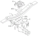
Fig. 27 is a schematic perspective view of the connection between the cross beam and the vertical shock absorber provided in the embodiment of the present application, fig. 28 is an enlarged schematic view of a region B in fig. 27, fig. 29 is an exploded schematic view of the connection between the cross beam and the vertical shock absorber provided in the embodiment of the present application, and fig. 30 is a schematic view of a layout position of the vertical shock absorber on the bogie provided in the embodiment of the present application. As shown in fig. 27 to 30, the end of the vertical damper 93 is provided with a bolt hole. The cross beam is provided with a mounting lug 29, the mounting lug 29 is provided with a mounting hole, the mounting lug 29 is further provided with a limiting surface 291, at least part of the limiting surface 291 is a plane, and the plane is used for abutting against a first side plane of the head of the first bolt.
The first fixing bolt 94 has a first screw 943 and a first bolt head 941 provided at one end of the first screw 943. The first screw 943 is engaged with the mounting hole and the bolt hole, and the first side surface 942 of the first bolt head 941 abuts against the limiting surface 291.
The upper end portion of the vertical damper 93 is attached to the body of the railway vehicle. The node of the lower end of the vertical shock absorber 93 is provided with a bolt hole. The bolt holes are arranged to penetrate in a direction perpendicular to the axial direction of the vertical damper 93. There may be two vertical dampers 93, and the two vertical dampers 93 are respectively disposed at both sides of the longitudinal center line. Correspondingly, the crossbeam is provided with two vertical shock absorber interfaces, is used for installing two vertical shock absorbers respectively. The cross beam is provided with two pairs of mounting lugs 29, each pair comprises two oppositely arranged mounting lugs 29; the ends of the vertical shock absorbers 93 are disposed between the opposing mounting ears 29. The mounting lugs 29 are provided on the side surfaces of the cross member main body 21 and extend in the longitudinal direction of the vehicle body.
The mounting lug 29 comprises a head end and a tail end, and the head end of the mounting lug 29 is connected with the beam main body of the beam; two opposite mounting ears 29, wherein the outer surface of the tail end of one mounting ear 29 facing away from the other mounting ear is recessed inwards relative to the outer surface of the head end of the mounting ear 29; the outer surface of head end is connected with the connection face between the outer surface of tail end, and the connection face has at least partly to form spacing face 291. In other words: the mounting ears 29 have a stepped configuration; the mounting lug 29 has a first step surface and a second step surface, and a limit surface 291 is formed at least in part on a connecting surface connecting the first step surface and the second step surface.
The first screw 943 of the first fixing bolt 94 is inserted into the bolt hole of the vertical damper 93 and the mounting hole of the mounting lug 29. One end of the first screw 943 is provided with a first bolt head 941, and the cross-sectional area of the first bolt head 941 is larger than that of the first screw 943. The first bolt head 941 has at least one first side flat surface 942.
The head of the bolt comprises four sides; wherein two opposite side surfaces are curved surfaces, and the other two opposite side surfaces are flat surfaces. At least a part of the joint between the first end and the second end of the mounting ear 29 is a plane, and the joint forms a limiting surface 291, which can abut against one of the first side planes 942 of the first bolt head 941 to achieve the purpose of limiting and preventing loosening.
It can be understood that: the structure of the first bolt head 941 is not limited thereto, and the embodiment is only illustrated here. For example, the first bolt head 941 may have a regular hexagon structure, and in this case, the first bolt head 941 has six side planes; the limit surface 291 of the cross beam can abut against one of the six side planes of the first bolt head 941.
In this example, the limit surface 291 of the mounting ear 29 can be in surface-to-surface contact with the first side surface 942 of the first bolt head 941 of the first fixing bolt 94, thereby forming a loose-proof structure for preventing the first fixing bolt 94 from loosening. Thus, when the first fixing bolt 94 is impacted and has a rotation tendency, the limiting surface 291 of the mounting lug 29 can apply an acting force on the first side surface 942 of the first bolt head 941 to offset the impact force for driving the first fixing bolt 94 to rotate, so as to prevent the first fixing bolt 94 from loosening, and ensure the connection reliability of the beam and the vertical shock absorber 93.
In one possible implementation manner, the first fixing bolt 94 further includes: a first nut 945 fitted with the first screw 943; first nut 945 is located opposite the end of first screw 943 facing away from first bolt head 941. The bogie further comprises: a first adjustment washer 944, the first adjustment washer 944 abutting between the first nut 945 and the corresponding mounting ear 29. The number of the first adjustment shims 944 is adjustable, and the number of the first adjustment shims 944 can be specifically set according to actual needs.
In this example, by adjusting the number of the first adjusting shims 944, the distance between the end of the first nut 945 and the corresponding mounting ear 29 can be adjusted, which further facilitates the improvement of the reliability of the connection between the vertical shock absorber 93 and the traction center pin.
The cross beam in this embodiment also provides an interface for connecting other components. As shown in fig. 1 and 4, the cross member main body 21 is also provided with an interface to which an anti-roll torsion bar is connected, such as: an anti-roll torsion bar mounting portion 215 is provided on a side surface of the cross beam body 21, and the anti-roll torsion bar mounting portion 215 is provided at a bottom portion of the cross beam body 21, extends in the longitudinal direction, and has a mounting hole extending in the vertical direction. Fig. 31 is a perspective view of an anti-roll torsion bar according to an embodiment of the present application. As shown in fig. 31, the anti-roll torsion bar 101 includes a lateral torsion bar 951 and vertical torsion bars 952 connected at both ends of the lateral torsion bar 951.
Therein, the transverse torsion bar 951 is horizontally arranged and extends in the transverse direction. Both end portions of the transverse torsion bar 951 are bent and extend outward in the longitudinal direction. The vertical torsion bar 952 extends in the vertical direction and is connected at its bottom end to a transverse torsion bar 951 by a torsion bar node 953. The top end of vertical torsion bar 952 is connected to the vehicle body by torsion bar node 953.
The anti-roll torsion bar 95 is connected to the cross member by a torsion bar mounting member 954, specifically to the anti-roll torsion bar mounting portion 215 by bolts. The torsion bar mounting member 954 includes an upper mounting member body and a lower mounting member body, the bottom of the upper mounting member body is provided with an upper concave arc groove, and the top of the lower mounting member body is provided with a lower concave arc groove; the upper mounting member body is butted with the lower mounting member body, and the upper concave arc groove is butted with the lower concave arc groove to form a round hole for the transverse torsion bar 951 to pass through. The upper and lower mounting bodies are bolted together and to the anti-roll torsion bar mounting portion 215.
As shown in fig. 1 and 4, the cross beam further provides an interface for connecting the anti-snake-shaped vibration damper 96, and specifically, an anti-snake-shaped vibration damper mounting plate 216 is provided at the outer end of the cross beam main body 21, specifically, two horizontal mounting plates arranged up and down are included, and a bolt hole is provided on the longitudinal end surface of each horizontal mounting plate for connecting the anti-snake-shaped vibration damper 96 through an elastic node.
Fig. 32 is a schematic structural view illustrating a cross member connected to an axle box through a single tie rod according to an embodiment of the present invention. As shown in fig. 4 and 32, the cross beam also provides an interface for connecting a single pull rod 97, the single pull rod 97 being connected between the cross beam and the axlebox 33 for transferring longitudinal forces between the cross beam and the axlebox. Specifically, the beam main body 21 is provided with a single-pull-rod connecting portion 217, and one end of the single pull rod 97 is provided with a pull-rod node 971 connected to the single-pull-rod connecting portion 217 through a bolt. The other end of the single pull rod 97 is provided with a pull rod node 971, and is connected with the axle box 33 through a bolt. The tie rod node 971 is an elastic node, is formed by vulcanizing metal and rubber, can buffer the buffer force between the single tie rod and the cross beam and the axle box, and can better adapt to longitudinal and transverse pulling forces.
Further, as shown in fig. 4, a nameplate mounting part 219 is disposed on the beam body 21 for mounting a nameplate of the bogie. The nameplate mounting portion 219 is an inclined plane with screw holes provided at four corners thereof for fixing the bogie nameplate to the beam by screws.
On the basis of the above technical solution, the cross beam is further provided with a center pin connecting part 218 for matching with a traction center pin. As shown in fig. 1, the traction center pin 6 has a top end connected to the vehicle body and a bottom end connected to the cross member, and the traction center pin 6 is used to transmit a longitudinal traction force or a braking force between the vehicle body and the bogie.
Fig. 33 is a schematic perspective view of a traction center pin and a longitudinal stopper connected to a cross beam provided in an embodiment of the present application, fig. 34 is a schematic sectional view of the traction center pin and the longitudinal stopper connected to the cross beam provided in the embodiment of the present application, fig. 35 is a schematic perspective view of the traction center pin and the longitudinal stopper connected to the embodiment of the present application, fig. 36 is a schematic structural view of the traction center pin provided in the embodiment of the present application, fig. 37 is an exploded schematic view of the traction center pin provided in the embodiment of the present application, fig. 38 is a schematic perspective view of the traction center pin and the cross beam connected to the embodiment of the present application, fig. 39 is a schematic perspective view of the traction center pin connected to a transverse damper provided in the embodiment of the present application, fig. 40 is a front view of the traction center pin connected to a transverse damper provided in the embodiment of the present application, fig. 41 is an enlarged schematic view of a region C in fig. 40, and fig. 42 is a sectional view of the traction center pin connected to a transverse damper provided in the embodiment of the present application, fig. 43 is an enlarged schematic view of region D in fig. 42.
As shown in fig. 33 to 43, the center pin 6 is pulled, and has a center pin main body 61, and the bottom of the center pin main body 61 is inserted into the gap between the two cross member single bodies 2. The two longitudinal stoppers 9 are respectively disposed on two opposite sides of the center pin main body 61, and the longitudinal stoppers 9 are disposed between the cross beam unit 2 and the center pin main body 61. The side of the centre pin body is provided with a stop contact area 61a, which stop contact area 61a forms an area on the pulling centre pin 6 for contact with the longitudinal stop 65. The stopper contact areas 61a may be provided on the front side and the rear side of the center pin body 61, wherein front refers to the front in which the rail vehicle travels.
Two longitudinal stops 65 are respectively arranged at the stop contact areas 61a of the traction center pin 6. One side of the longitudinal stopper 65 is in contact with the stopper contact region 61a, and the other side is connected to the center pin connection portion 218 of the cross beam by a plurality of stopper fixing bolts 654. In a specific implementation: the center pin connecting part 218 is arranged on the cross beam connecting arm 22, the center pin connecting part 218 is relatively positioned in the middle of the cross beam connecting arm 22, one or more first adjusting shims are arranged between the longitudinal stopping part 65 and the cross beam, and the distance between the longitudinal stopping part 65 and the traction center pin is adjusted by increasing or decreasing the first adjusting shims. The longitudinal stop 65 is in contact with the traction center pin to transmit longitudinal traction forces and longitudinal braking forces.
The traction center pin 6 further includes a mounting arm 62 provided at a lower portion of the center pin body 61 and a lifting piece 64 provided at a lower end of the center pin body 61. The mounting arm 62 is used to mount a transverse damper 98. The lifting piece 64 is used for contacting with the cross beam when the vehicle body is lifted, and the function of lifting the bogie is realized.
Specifically, the center pin main body 61 may include a columnar structure and a vehicle body connecting arm. The upper end of the columnar structure can be provided with two transition sections which are oppositely arranged; the transition section can be a curve and is used for being smoothly connected with the vehicle body connecting arm. The vehicle body connecting arms are connected to the transition sections of the columnar structures and are respectively positioned on two sides of each transition section along the longitudinal direction. And one side of the vehicle body connecting arm, which deviates from the transition section, is provided with a bolt hole. The vehicle body connecting arm is used for being connected with a vehicle body.
The lower end of the columnar structure may have oppositely disposed mounting arms 62, the mounting arms 62 being used to mount the transverse damper 98. The mounting arm 62 is located relatively below the longitudinal stop 65. The mounting arm 62 is fixedly attached to the lateral damper 98 by bolts.
Illustratively, the mounting arms 62 have two pairs, and the two pairs of mounting arms 62 are disposed on opposite sides of the center pin body 61. Each pair of mounting arms 62 has two oppositely disposed. The node points at the ends of the transverse damper 98 are interposed between the two opposing mounting arms 62 of the same pair. Each mounting arm 62 is provided with a mounting hole, and the mounting holes in the mounting arms 62 can be aligned with the bolt holes of the end nodes of the corresponding transverse shock absorbers. The bolt holes penetrate through the transverse shock absorber along the direction perpendicular to the axial direction of the transverse shock absorber.
The second fixing bolt 99 has a second screw rod 993, and the second screw rod 993 is inserted into the bolt hole of the lateral damper 98 and the mounting hole of the mounting arm 62. One end of the second screw rod 993 is provided with a second bolt head 991, and the cross-sectional area of the second bolt head 991 is larger than that of the second screw rod 993. The second bolt head 991 has at least one second side flat 992. For example, the second bolt head 991 includes four sides; wherein two opposite side surfaces are curved surfaces, and the other two opposite side surfaces are flat surfaces.
The pulling core pin 6 is further provided with a limiting surface 63, and at least part of the limiting surface 63 is a plane surface for surface-to-surface contact with the side plane of the second bolt head 991. Illustratively, the outer surface of one of the two oppositely disposed mounting arms 62 of the same pair, which faces away from the other mounting arm 62, is recessed inwardly with respect to the corresponding side of the center pin body 61; the outer surface of the mounting arm 62 is connected to a corresponding side surface of the center pin body 61 by a connecting surface, and at least a portion of the connecting surface forms a stopper surface 63.
In other words: the mounting arm 62 forms a stepped structure with the center pin main body 61; the outer surface of the mounting arm 62 is a first step surface, the side surface of the corresponding side of the center pin main body 61 is a second step surface, and a connecting surface connecting the first step surface and the second step surface at least partially forms a limiting surface 63.
In this example, the stopper surface 63 of the traction center pin 6 can be in surface-to-surface contact with the second side plane 992, thereby forming a loosening prevention structure for preventing the second fixing bolt 99 from loosening. Thus, when the second fixing bolt 99 is impacted to have a rotation trend, the limiting surface 63 of the traction center pin 6 can exert an acting force on the side plane of the head of the bolt to offset the impact force for driving the second fixing bolt 99 to rotate, so that the purpose of preventing the second fixing bolt 99 from loosening is achieved, and the reliability of connection between the traction center pin 6 and the transverse damper 98 is favorably ensured.
Optionally, the second fixing bolt 99 further includes: a second nut 995 engaged with the second screw 993; second nut 995 is located opposite the end of second screw 993 facing away from second bolt head 991. The bogie further comprises: a third adjusting shim 994, the third adjusting shim 994 being disposed between the second nut 995 and the corresponding mounting arm 62. A third adjustment shim 994 is used to adjust the spacing between the end of the nut and the corresponding mounting arm 62.
The lifting element 64 is connected to the center pin body 61 by a plurality of threaded pins spaced apart. Illustratively, the threaded pins may be two. A threaded pin may be disposed between the two pairs of mounting arms 62. The center pin main body 61 is provided with a fitting hole 61b to be fitted with a threaded pin. The fitting hole 61b may be disposed near the screw hole of the mounting arm 61 in the up-down direction to facilitate a more compact structure of the traction center pin 6. For example, the center of the fitting hole 61b may be located on the same line as the center of the bolt hole on the mounting arm 62; the center of the fitting hole 61b is also higher than the center of the bolt hole in the mounting arm 62.
The lifting piece 64 includes: a lift mounting body 641 and a lift stop 642. Wherein the lifting installation body 641 is connected with the center pin body 61; opposite end portions of the lift mounting body 641 protrude out of the center pin body 61 in a direction perpendicular to the axial direction of the center pin body 61, respectively. The lifting stop blocks 642 are respectively disposed at two opposite ends of the lifting installation body 641; the lifting stop 642 is used to abut against the cross beam when lifting the traction center pin 6.
In this example, under normal working conditions, a proper distance exists between the lifting stop block 642 and the cross beam, when the vehicle body is lifted, the traction center pin 6 is lifted, and the lifting stop block 642 is in contact with the cross beam, so that the lifting function of the bogie is realized. Further, the lifting and mounting body 641 may be connected to the towing pin body by a plurality of bolts disposed at intervals, so as to further improve the reliability of the connection between the lifting member 64 and the towing center pin 6.
In addition, a second adjusting washer 643 may be further disposed between the lifting stop block 642 and the lifting mounting body 641, and the second adjusting washer 643 is used for adjusting the distance between the lifting stop block 642 of the lifting member 64 and the cross beam. The adjusting shim is a preset multilayer shim, when the height of the floor surface needs to be kept by adding a pad below/above the air spring after the wheel is worn, the traction center pin 6 is respectively connected with the vehicle body and the whole lifting crane, so that the traction center pin 6 and the whole lifting crane are improved along with the vehicle body, the distance between the bottom of the cross beam and the lifting crane is reduced, and the distance between the bottom of the cross beam and the lifting crane can be kept in a specified size by reducing the number of proper shims.
Optionally, two lift stop blocks 642 and two pairs of mounting arms 62 are disposed on each of the four lateral sides of the center pin body 61 to prevent the cross damper from interfering with the lift member 64.
The crossbeam that this embodiment provided provides the interface of a plurality of parts, has integrateed the installation of a plurality of parts, integrates the degree height, has saved spare parts such as a large amount of mount pads in comparison in traditional bogie, reduces spare part quantity, reduces processing work load, has reduced manufacturing cost.
The bogie provided by the present embodiment may be a non-powered bogie, as shown in fig. 1. Or may be a power bogie: fig. 44 is a perspective view of a power bogie provided in an embodiment of the present application. As shown in fig. 44, if the traction motor 91 is disposed on the wheel set, the bogie is a power bogie, and the traction motor 91 may be a direct drive motor, and the rotor of the direct drive motor directly drives the axle to rotate.
Fig. 45 is a schematic connection diagram of a direct drive motor and an axle provided in the embodiment of the present application, fig. 46 is a schematic cross-sectional view of the direct drive motor and the axle provided in the embodiment of the present application, and fig. 47 is a partially enlarged schematic view of a portion E in fig. 46. As shown in fig. 45 to 47, the axle boxes 33 are attached to both end portions of the axle 31 by seal bearings 333. Direct drive motor 91 has a stator 911, a rotor 913, and an end cap 912, rotor 913 being mounted to axle 31, for example: rotor 913 may be an interference fit with axle 31, and rotor 913 may be rotatable with axle 31. Stator 911 is mounted to end cap 912 by a plurality of fixing bolts and may be supported by an inner edge of end cap 912. End cap 912 is coupled to axle housing 33. The dust retainer 925 is connected at one end to the sealed bearing 333 and at the other end to the end cap 912 and forms a labyrinth seal with the end cap 912.
The end cover 912 comprises a cover plate, an inner edge which protrudes inwards is arranged on the inner side of the cover plate facing to the other end cover 912, the outer diameter of the inner edge is smaller than that of the cover plate, the end part of the stator 911 is sleeved on the inner edge, and a plurality of fixing bolts distributed at intervals penetrate through the cover plate and the stator 911 to enable the stator 911 to be in threaded connection with the cover plate, so that the stator 911 and the end cover 912 are reliably detachably connected.
The axle housing 33 is provided to the axle 31 through a seal bearing 333 so that there can be relative rotation between the axle 31 and the axle housing 33. The sealed bearing 333 includes an inner ring, a roller, an outer ring, and a seal. The roller sets up between inner circle and outer lane, and the junction of outer lane and inner circle is provided with the sealing member, forms labyrinth seal structure between outer lane, sealing member and the inner circle to effectively avoid self lubricating oil to reveal get into and directly drive in the motor 91, and can avoid directly driving particulate matters such as dust that the motor 91 during operation produced and get into in the sealed bearing 333, thereby do benefit to the life who prolongs sealed bearing 333 and directly drive motor 91, reduce rail vehicle's maintenance cost.
A limit ring is arranged at one end of the axle box 33 facing the end cover 912; one end of end cover 912 facing axle box 33 is provided with a mounting boss, which is inserted into the limit ring. Therefore, when the direct-drive motor 91 is assembled, the end cover 912 of the direct-drive motor 91 is positioned relative to the axle box 33, the end cover 912 and the axle box 33 are screwed conveniently through the fixing bolt, and the reliability of connection between the direct-drive motor 91 and the axle box 33 is ensured.
Further, as shown in fig. 47, a dust-proof retainer 925 is provided between the seal bearing 333 and the end cap 912, one end of the dust-proof retainer 925 abuts against the seal bearing 333, and the other end of the dust-proof retainer 925 and the end cap 912 form a labyrinth seal structure. Therefore, a sealing structure is also formed between the sealing bearing 333 and the end cover 912, so that the lubricating oil in the sealing bearing 333 is further effectively prevented from leaking into the direct drive motor 91, and particulate matters such as dust generated during the operation of the direct drive motor 91 can be prevented from entering the sealing bearing 333. Therefore, the service lives of the sealing bearing 333 and the direct drive motor 91 are further prolonged, and the maintenance cost of the railway vehicle is reduced.
In one possible implementation, the dust-proof block 925 includes: a mounting body 931, an extension ring 932, and a plurality of annular seal teeth 933. The head end of the mounting body 931 abuts against the sealed bearing 333, and the tail end of the mounting body 931 abuts between the end cap 912 and the axle 31. Extension ring 932 is disposed at the aft end of mounting body 931 and is located on the inboard side of endcap 912 facing away from axle housing 33. A plurality of annular seal teeth 933 are disposed on one side of the extension ring 932 facing the inner side wall of the end cover 912 and respectively engaged with the teeth grooves disposed on the inner side wall of the end cover 912, so that a labyrinth is formed between the end cover 912 and the dust-proof retainer 925.
In a specific implementation, the head end of the mounting body 931 may abut against the outer end surface of the sealing bearing 333, or the head end of the mounting body 931 abuts between the sealing bearing 333 and the axle 31, so as to achieve the sealing connection between the dust-proof retainer 925 and the sealing bearing 333.
The mounting body 931 may be sleeved on a corresponding position of the axle 31. The matching section of the axle 31 matched with the dustproof retainer ring 925 comprises a first part and a second part, wherein the outer diameter of the first part is smaller than that of the second part; the mounting body 931 is shaped to fit the mating segment, the first segment of the mounting body 931 fits into the first portion, and the tail end of the mounting body 931 fits into the second portion. Wherein, the first part and the second part of the matching section of the axle 31 can be smoothly transited; the head end and the tail end of the mounting body 931 are smoothly transitioned.
The aft end of the mounting body 931 is provided with an upwardly extending extension ring 932, and the extension ring 932 is located on the inboard side of the endcap 912 facing away from the sealed bearing 333. One side of the extension ring 932 facing the inner side wall of the end cover 912 is provided with a plurality of annular seal teeth 933 distributed at intervals, and the annular seal teeth 933 are respectively matched with tooth grooves 912a arranged on the inner side wall of the end cover 912, so that labyrinth sealing is formed between the end cover 912 and the dust-proof retainer ring 925. Wherein the extension ring 932 extends a set distance in a radial direction thereof to facilitate placement of the annular seal tooth 933. Annular seal teeth 933 extend a set distance axially therealong to facilitate the formation of a longer flow path.
The annular seal teeth 933 of the dust-proof check ring 925 and the tooth grooves 912a of the end cover 912 form a radial staggered tooth type labyrinth seal structure. In general, in the labyrinth seal structure, the flow passage frictional resistance is related to the length and the cross-sectional shape of the flow passage. Specifically, the flow channel frictional resistance is proportional to the length of the flow channel, and the flow channel frictional resistance is proportional to the cross-sectional area.
In the example, a radial rectangular tooth staggered tooth labyrinth with two pairs of staggered teeth can be adopted, so that the length of a flow passage can be increased, the friction resistance can be increased, and the movement speed of lubricating oil or dust in the labyrinth sealing structure can be reduced.
In this example, a wide flow passage and a narrow flow passage are arranged in a staggered manner, so as to further reduce the movement speed of the lubricating oil or the dust in the labyrinth seal structure. Taking lubricating oil as an example, under the condition of a certain flow rate, the flow rate and the sectional area of the lubricating oil are in inverse proportion, the flow rate of the lubricating oil is increased when the lubricating oil passes through a narrow flow passage, a wide flow passage is arranged behind the narrow flow passage, the sectional area of the wide flow passage is increased, and the flow rate is reduced, so that the flow passage is circularly changed in a narrow and wide mode until the flow rate of the lubricating oil is zero, and the sealing purpose is achieved.
Illustratively, the annular seal tooth 933 has two first surfaces extending axially therealong and a second surface extending radially therealong, the second surface being connected to the two first surfaces, the flow channel formed between the first surface and the corresponding sidewall of the tooth slot 912a being a relatively wide flow channel, and the flow channel formed between the second surface and the corresponding sidewall of the tooth slot 912a being a relatively narrow flow channel. Extension ring 932 has a third surface that is coupled to the first surface of annular seal tooth 933, and the flow path formed between the third surface and the inner sidewall of end cap 912 is a relatively narrow flow path. So, narrow and small runner and the crisscross setting of broad runner, that is, the runner is narrow and small, the reciprocating change of broad circulation, reduces the velocity of motion of lubricating oil or dust in labyrinth seal structure, reaches sealed purpose.
The operation principle of the labyrinth sealing structure of the sealed bearing 333 may be similar to that of the labyrinth sealing structure formed by the dust-proof retainer ring 925 and the end cover 912, and details are not repeated in this embodiment. In the present example, a labyrinth seal structure formed by the end cover 912 and the dustproof check ring 925 can prevent dust impurities generated in the working process of the direct drive motor 91 from entering the axle box 33 to cause bearing damage, and prolong the service life of the bearing; a small amount of grease or oil can be prevented from leaking into the direct drive motor 91 by the labyrinth structure of the seal bearing 333.
The bogie still includes: one end of the motor balancing rod 92 is flexibly connected with the stator 911 of the direct drive motor 91, and the other end of the motor balancing rod 92 is flexibly connected with the secondary mounting base 8. In a specific implementation, the direct drive motor 91 may be connected to the secondary mounting base 8 through two motor balance rods 92, specifically, one end of each of the two motor balance rods 92 is connected to the middle of the direct drive motor 91, and the other end of each of the two motor balance rods 92 is connected to the secondary mounting base 8, so as to ensure the connection reliability between the direct drive motor 91 and the secondary mounting base 8.
Fig. 48 is a schematic perspective view of a motor balancing bar according to an embodiment of the present application, fig. 49 is a cross-sectional view of a connection between a bar body and a node of the motor balancing bar according to the embodiment of the present application, fig. 50 is an exploded schematic view of the motor balancing bar according to the embodiment of the present application, and fig. 51 is a schematic structural view of a secondary suspension mount connected to a traction motor through the motor balancing bar according to the embodiment of the present application. As shown in fig. 48 to 51, the motor balance bar 92 includes: a lever body 921 and two resilient nodes 922. The two elastic nodes 922 are respectively arranged at two ends of the rod body 921; one of the elastic nodes 922 is connected to the stator 911 of the direct drive motor 91, and the other elastic node 922 is connected to the secondary mounting base 8.
The shaft 921 may be made of carbon fiber material. The carbon fiber material has the advantages of high modulus, good design, compositability, light weight, high strength and the like, and is high-temperature resistant and corrosion resistant. Therefore, the rod body 921 made of the carbon fiber material in this example has sufficient strength and high material utilization.
The rod body 921 may be a variable section rod. The cross-sectional area of the end portion of the rod body 921 is larger than the cross-sectional area of the middle portion of the rod body 921. In this example, by setting the cross-sectional area of the end portion of the rod body 921 to be relatively large, the strength of the end portion of the rod body 921 is made high, which is beneficial to ensuring the connection reliability of the driving motor and the cross beam; the middle part of the rod body 921 is arranged, so that the rod body 921 can adapt to the distance between the direct drive motor 91 and the cross beam; by providing a relatively small cross-sectional area of the middle portion of the lever body 921, it is beneficial to reduce the cost of the motor balancing lever 92. Wherein, the length in the middle part of the pole body 921 can be set according to actual need.
The outer surface of the middle of the node 922 protrudes out of the two end parts of the node 922; the middle part of the node 922 is connected to the rod body 921; the middle of node 922 has a metal and rubber vulcanized elastic portion to achieve an elastic connection. The outer ring in the middle of the node 922 is in transition fit with the rod body 921, and the middle of the node 922 can be pressed into the mounting hole in the end part of the rod body 921 in a press-fitting mode. The two ends of node 922 are connected to stator 911 or a cross beam of direct drive motor 91.
The end part of the node 922 at one end of the rod body 921 can be connected to the stator 911 of the direct drive motor 91 through a fixing bolt and an adjusting shim, and the number of the adjusting shims is adjustable; and/or, the end of node 922 may also be connected to stator 911 of direct drive motor 91 by a threaded pin. The connection of the end of the node 922 at the other end of the rod 921 to the cross beam may be similar to the connection of the node 922 to the stator 911 of the direct drive motor 91.
Further, a metal retainer ring 923 is embedded in the end of the rod body 921; the metal collar 923 has mounting holes to mount the nodes 922. The metal retainer ring 923 is provided with a positioning boss 923a along its axial one end, and the positioning boss 923a is arranged on the inner hole wall of the mounting hole of the metal retainer ring 923 and extends inwards. The positioning boss 923a is located at one end of the middle portion of the node 922 and is used for limiting the middle portion of the node 922 in the installation hole of the metal retainer ring 923. The other end of the metal retainer ring 923 is provided with a clamping groove 923b, and the clamping groove 923b is arranged on the inner hole wall of the mounting hole of the metal retainer ring 923. The motor balancing bar 92 further includes: spring rand 924, spring rand 924 card is located in the draw-in groove 923b of metal retaining ring 923, and spring rand 924 is located the middle part of node 922 and deviates from the one end of location boss 923a, and spring rand 924 and location boss 923a are together with the middle part location of node 922 in metal retaining ring 923 to break away from in the mounting hole of metal retaining ring 923 is followed to the middle part of node 922, thereby ensure the reliability of being connected of node 922 and the body of rod 921, ensure the reliability of being connected of directly driving motor 91 and crossbeam.
When assembling motor balancing pole 92, in the mounting hole of the middle part pressure equipment of node 922 to the body of rod 921 tip metal retaining ring 923 earlier, and make the middle part of node 922 offset with the location boss 923a of metal retaining ring 923, then go into the draw-in groove 923b of metal retaining ring 923 with spring rand 924 card. Wherein, the spring clip 924 is an open and elastic clip to facilitate the installation of the spring clip 924. In this example, the direct drive motor 91 is flexibly connected with the cross beam through the motor balancing rod 92, so as to facilitate the vibration and impact between the axle 31 and the cross beam to be buffered.
Furthermore, the bogie is also provided with a bogie cabin which is arranged outside the main structure of the bogie in a surrounding way and is used for protecting the bogie and preventing sundries on a railway line from impacting the bogie; but also plays a role in noise reduction and air flow guidance. The two ends of the brake hanger 7 are respectively provided with interfaces for connecting with the bogie cabin, such as cabin mounting holes 75, and are connected with the bogie cabin through bolts.
Fig. 52 is a schematic view illustrating the mounting of a bogie compartment and a bogie of a railway vehicle according to an embodiment of the present invention, fig. 53 is a schematic view illustrating the bogie compartment shown in fig. 52, fig. 54 is an exploded schematic view illustrating a main compartment plate and a side compartment plate of the bogie compartment shown in fig. 53, fig. 55 is an exploded view illustrating a connection structure of the main compartment plate and the side compartment plate shown in fig. 54, fig. 56 is an assembled view illustrating the connection structure of the main compartment plate and the side compartment plate shown in fig. 55, fig. 57 is a schematic view illustrating the rotation prevention of the bogie compartment shown in fig. 54, fig. 58 is an enlarged view illustrating a portion of the bogie compartment shown in fig. 53, fig. 59 is an enlarged view illustrating a portion of the bogie compartment shown in fig. 58, fig. 60 is an exploded schematic view illustrating the side compartment plate and a first link of the bogie compartment shown in fig. 53, fig. 61 is an exploded schematic view illustrating a connection structure of the side compartment plate and first and second link of the first link and the second link of the first link, fig. 62 is an exploded schematic view illustrating a spring fixing seat of the first link and the bogie, fig. 63 is an exploded view of a brake hanger connecting rod of the second link frame and a brake unit hanger of the bogie, fig. 64 is an exploded view of a beam connecting rod of the second link frame and a beam of the bogie, fig. 65 is a perspective view of a first link frame of the bogie bay shown in fig. 53, and fig. 66 is a perspective view of a second link frame of the bogie bay shown in fig. 54.
As shown in fig. 52-66, the bogie cabin 102, includes a cabin assembly comprising: a main deck 1021 and two side decks 1022, the two side decks 1022 being secured to both sides of the main deck 1021 and enclosing with the main deck 1021 a cavity for receiving the railway vehicle bogie 101.
The inner side of the main deck plate is fixed with the front or the rear of the bogie, and the front or the rear of the bogie is separated from the outside; the inner sides of the two side deck boards are fixed with the sides of the bogie, and the sides of the bogie are separated from the outside.
The main deck and the two side decks form a semi-enclosed structure that forms a cavity for receiving a railway vehicle truck. When the bogie cabin is installed with the bogie, the inner side of the main cabin plate is fixed with the front or the rear of the bogie, so that the front or the rear of the bogie is separated from the outside, and the inner sides of the two side cabin plates are fixed with the sides of the bogie, so that the sides of the bogie are separated from the outside. Therefore, the cabin body assembly is connected with the bogie and wraps the front, the rear and the side of the bogie, the bogie cabin blocks the noise in the bogie cabin from being spread outwards, and the train far-field noise reducing effect is achieved. Meanwhile, the air flow is guided to flow along the outer surface of the bogie cabin, the air flow entering the inner part of the bogie cabin is reduced, the air resistance of the bogie area in operation can be reduced, the resistance reduction effect is achieved, and therefore the pneumatic performance is improved.
A first preset interval is kept between the main cabin plate and the bogie, and a second preset interval is kept between the side cabin plate and the bogie. The main deck 1021 is specifically configured to cover, when fixed to the bogie, the inner edges of the two side members of the bogie frame in the width direction and the members located between the two side members of the bogie frame in the height direction.
The whole bogie is a structure with a lower middle part and higher two sides. The main deck covers a portion slightly lower in the middle of the bogie, i.e., inner edges of both side sills of the bogie frame in the width direction, and members located between both side sills of the bogie frame in the height direction. The main cabin plate can cover the front or the rear of the bogie, so that the influence on the pneumatic performance caused by the exposure of the front or the rear of the bogie is avoided. Meanwhile, the middle part of the main deck plate is slightly lower, so that the interference with a vehicle body and an energy absorption device of the railway vehicle is avoided.
The side deck 1022 is specifically used for covering the side sill of the bogie frame and the side of the bogie in the width direction, covering the upper surface of the side sill of the bogie frame above in the height direction, and covering the member attached to the side sill of the bogie frame below in the height direction when fixed to the bogie. The two side deck boards cover the higher parts of the two sides of the bogie respectively. The side cabin plate can cover the front, the rear and the side of the side beam of the bogie, so that the side of the bogie is prevented from being exposed to the outside and the pneumatic performance is prevented from being influenced.
The main deck 1021 is a main deck having a streamlined outer surface, and the side deck 1022 is a side deck having a streamlined outer surface. The outer surfaces of the main deck boards and the outer surfaces of the side deck boards are used for guiding airflow along the outer surface of the bogie cabin, and airflow entering the bogie cabin is reduced. The outer surface of the main deck plate and the outer surface of the side deck plate are in streamline shapes, so that the front or the rear of the bogie is prevented from being exposed outside, the side exposed area of the bogie is reduced, the wind resistance is reduced, and the pneumatic performance is influenced.
The side deck boards are particularly used for covering the braking device of the bogie on the side of the side deck boards far away from the main deck board when the side deck boards are fixed with the bogie. The braking device is located on the outer side of the middle of the bogie, and the side of the side cabin plate, which is far away from the main cabin plate, covers the braking device of the bogie, so that the exposed area of the side of the bogie is reduced, and the pneumatic performance is better. Meanwhile, the side cabin plate coats the braking device, and meanwhile, the outside is also separated, so that the noise of the bogie is reduced.
The side deck panels are in particular also used for guiding the air flow entering from the upper and/or lower end of the main deck to the brake devices of the bogie in order to cool the brake devices. When the brake device is used for braking, a large amount of heat and noise are generated. By designing the structure of the side deck, the air flow entering from the upper end and/or the lower end of the main deck is guided to the brake device of the bogie, and the temperature of the brake unit is reduced.
The truck compartment also includes sound absorbing panels 1025, with sound absorbing panels 1023 secured to the inside of the main deck panel and/or panels 1023 secured to the inside of the side deck panels.
The main deck plate is made of lightweight composite materials, and the side deck plates are made of lightweight composite materials. The lightweight composite material includes a carbon fiber composite material, a glass fiber composite material, and the like.
The sound-absorbing plate enables noise generated by the bogie to be partially absorbed by the sound-absorbing plate, and further noise of the bogie is greatly reduced. The main cabin plate and the side cabin plates are made of light composite materials, and the weight of the bogie cabin is smaller.
The bogie bay further comprises a first connecting frame 1031 comprising: a side deck connection bar 10311 and a main deck connection bar 10312. Wherein, one end of the side deck connecting rod 10311 is connected with the inner side of the side deck 1022 through a rubber node, and the other end has a fastening seat interface 10311 a. One end of the main deck connecting rod 10312 is connected to the inner side of the main deck 1021 via a rubber node, and the other end is fixed to the side deck connecting rod 10311. Wherein, a series of fixing seat interfaces 10311a of the side deck connecting rod is used for connecting with a series of spring fixing seats of the bogie.
The first connecting frame is taken as a whole, one end of the first connecting frame is connected with a primary suspension mounting seat 41 of the bogie through a primary fixing seat interface of the side deck connecting rod, the other end of the first connecting frame is connected with the inner side of the side deck through the side deck connecting rod through a rubber node, and is connected with the inner side of the main deck through the main deck connecting rod through a rubber node, so that the bogie, the main deck and the side deck are connected. And the rubber node is used, so that the vibration of the bogie cabin in the running process of the vehicle can be alleviated.
A tie seat interface 10311a of the side deck connecting rod and a tie spring fixing seat of the bogie are fixedly connected through a fixing nut and a fixing bolt. The side deck connection bar 10311 is higher than the main deck connection bar 10312.
The first link 1031 further includes a first link reinforcing bar 10313, one end of which is fixed to the side deck connecting bar 10311 and the other end of which is fixed to the main deck connecting bar 10312, so as to reinforce the strength of the first link 1031. The existence of the first connecting frame reinforcing rod enables the strength of the whole first connecting frame to be higher.
Specifically, the position where the main deck connecting rod is connected with the main deck is located in the middle of the main deck in the height direction; the connecting position of the side deck connecting rod and the side deck is consistent with the height of a series of spring fixing seats of the bogie; the shapes of the main deck plate connecting rod and the side deck plate connecting rod can be correspondingly designed according to the bogie, so that the purpose of avoiding the bogie is achieved.
A rubber node 1044 is fixed at one end of the side deck plate connecting rod, which is far away from the fastening seat interface 10311a, and is connected with the inner side of the side deck plate 1022 through the rubber node; the main deck plate connecting rod is fixed with a rubber node 1044 at one end far away from a fastening seat interface 10311a, and is connected with the inner side of the main deck plate 1021 through the rubber node.
The bogie bay further comprises a second link frame 1032, the second link frame 1032 comprising: and one end of the brake shoe connecting rod 10321 is connected with the position, far away from the main cabin plate, of the inner side of the side cabin plate through a rubber node, and the other end of the brake shoe connecting rod 10321a is provided with a brake shoe interface 10321 a. The brake shoe interface 10321a of the brake shoe connecting rod is for connection with the brake shoe of the bogie. Specifically, the height direction of the brake hanging seat connecting rod is consistent with the height of the brake hanging seat, so that the brake hanging seat connecting rod is simple in structure and less in material consumption. The brake hanger interface 10321a of the brake hanger connecting rod is fixedly connected with the brake hanger through a fixing bolt 1041 and a fixing nut 1042.
The second link still includes: a beam connecting rod 10322, one end of which is connected with the position of the inner side of the side deck 1022 far away from the main deck through a rubber node, and the other end of which is provided with a beam interface 10322 a; the beam connecting rod 10322 is located below the brake shoe connecting rod 10321; wherein the beam interface 10322a of the beam connecting rod is used for connecting with the beam of the bogie. The beam connecting rod is consistent with the height of the beam of the bogie in the height direction, so that the beam connecting rod is simple in structure and less in material consumption.
The beam interface 10322a of the beam connecting rod and the beam of the bogie are fixedly connected by a fixing bolt 1041, a washer 1043 and a fixing nut 1042. One end of the cross beam connecting rod, which is far away from the cross beam interface 10322a, is fixed with a rubber node 1044, which is connected through the inner side of the rubber node side deck 1022.
One end of the brake hanger connecting rod, which is far away from the brake hanger interface 10321a, is fixed with a rubber node 1044, and is connected with the inner side of the side deck plate through the rubber node.
The second link still includes: one end of the second link reinforcing bar 10323 is fixed to the brake hanger connecting bar 10321, and the other end is fixed to the cross beam connecting bar. The second link reinforcing bars 10323 are provided in two and parallel. The existence of second link reinforcement pole for the intensity of whole second link is higher.
The second connecting frame is taken as a whole, one end of the second connecting frame is connected with the bogie through the braking hanging seat connector and the beam connector, and the other end of the second connecting frame is connected with the side cabin plate through the braking hanging seat connecting rod and the beam connecting rod through rubber joints, so that the bogie and the side cabin plate are connected. And the vibration of the bogie cabin in the running process of the vehicle can be alleviated by using the rubber node.
In implementation, the number of the cabin components is two, the beam connectors 10322a of the two beam connecting rods are connected, and the connecting position is used for being connected with the beam of the bogie, so that the space for connecting with the beam is saved.
Both sides of the main deck plate are respectively provided with a main deck plate through hole 10211; one side of the side cabin plate close to the main cabin plate is provided with a step hole-shaped side cabin plate through hole 10221, one section of the side cabin plate through hole 10221 with a larger diameter is far away from the main cabin plate, and the hole wall is of an anti-rotation polygonal structure.
One end of the screw of the first anti-rotation bolt 1024 near the head is formed with a first anti-rotation platform 10241 in the shape of a right prism. The screw rod of the first anti-rotation bolt 1024 passes through the side cabin plate through hole and the main cabin plate through hole, and the first anti-rotation platform 10241 is clamped in a section with a larger diameter of the side cabin plate through hole and is matched with the first anti-rotation nut 10251 to fix the main cabin plate and the side cabin plate.
The first prismatic outer peripheral face of preventing the revolving stage of first preventing of revolving bolt cooperatees with the great section pore wall shape of diameter of side deck board through-hole for the first prismatic of preventing the revolving stage is blocked in the great section of diameter of side deck board through-hole, prevents first preventing the revolving stage at side deck board through-hole internal rotation, and the stability of connecting is higher. The head of the first anti-rotation bolt is clamped at one side of the through hole of the side cabin plate. Specifically, the dimension of the first rotation preventing table in the direction perpendicular to the axial direction of the first rotation preventing bolt is larger than the diameter of the screw of the first rotation preventing bolt.
The main deck includes main deck mount pad, includes: main deck board mount 10212, anti-rotation mount 1026 and first anti-rotation spring plate 1027. Main deck mount mounts 10212 are formed on both sides of main deck 1021. The rotation preventing base 1026 is fixed on the main deck board mounting base body 10212, the rotation preventing base 1026 is provided with two rotation preventing convex strips 10261 which are oppositely arranged, the main deck board through hole 10211 is arranged between the two rotation preventing convex strips 10261 and penetrates through the main deck board mounting base body 10212 and the rotation preventing base 1026, and the middle part of the rotation preventing convex strip 10261 is provided with a rotation preventing groove 10262. The first anti-rotation elastic piece 1027 has a circular through hole. The screw of the first anti-rotation bolt 1024 also passes through the circular through hole of the first anti-rotation elastic sheet 1027, and the first anti-rotation nuts 10251 are two nuts pressed on two sides of the first anti-rotation elastic sheet respectively, and two ends of the first anti-rotation elastic sheet 1027 are respectively clamped in the anti-rotation grooves 10262.
The first anti-rotation elastic piece can generate certain elastic deformation, so that the first anti-rotation elastic piece can adapt to certain deformation and moderate certain vibration. The anti-rotation groove of the anti-rotation convex strip is matched with the first anti-rotation elastic piece, so that the anti-rotation at one end of the screw rod of the first bolt is realized, and the main cabin plate and the side cabin plate are more stably fixed.
Specifically, the anti-rotation seat is fixed on the main deck plate mounting seat body through a bolt and a gasket. The advantage of preventing the swivel mount to set up alone lies in, prevent that the swivel mount atress is damaged the back, only need change prevent the swivel mount can, main deck is not influenced.
The main deck via 10211 is an elongated main deck via. The strip-shaped main deck plate through hole has the advantages that the requirement on the machining precision of the main deck plate through hole is low, and the assembly is easier to realize.
The first anti-rotation elastic piece 1027 is a n-shaped first anti-rotation elastic piece, two flanges at the bottom end are respectively clamped in the two anti-rotation grooves, and a circular through hole of the first anti-rotation elastic piece is arranged at a cross arm at the top end of the first anti-rotation elastic piece. The first anti-rotation elastic sheet in the shape of a Chinese character 'ji' can elastically deform to adapt to certain deformation and moderate certain vibration. Specifically, a gasket is arranged between the first anti-rotation nut and the first anti-rotation elastic sheet.
A plurality of main deck board mounting seat bodies 10212 are respectively arranged on two sides of the main deck board from top to bottom at intervals. The number of the anti-rotation seats 1026, the first anti-rotation elastic pieces 1027 and the side deck through holes 10221 is matched with the number of the main deck mounting seats. Specifically, two sides of the main deck plate are respectively provided with three main deck plate mounting seats at intervals from top to bottom. The number of the main deck plate installation seats which are respectively arranged on the two sides of the main deck plate from top to bottom at intervals is selected according to the actual situation.
The bogie cabin still includes prevents changeing mounting structure, includes: anti-rotation boss 10222, anti-rotation recess 1033, and second anti-rotation bolt 1034. An anti-rotation boss 10222 is formed on the inner side of the deck, the anti-rotation boss 10222 having a stepped hole; the hole wall of a section of the step hole of the anti-rotation boss with a larger diameter is of an anti-rotation polygonal structure; the cabin plate comprises a main cabin plate and a side cabin plate. The anti-rotation recess 1033 has a through hole, and is fastened to the anti-rotation boss. A second anti-rotation stand 10341 in a shape of a straight prism is formed at one end of the screw of the second anti-rotation bolt 1034 near the head. The screw of the second anti-rotation bolt 1034 passes through the stepped hole of the anti-rotation boss 10222 and the through hole of the anti-rotation recess 1033, and the second anti-rotation boss 10341 is clamped in a section with a larger diameter in the stepped hole of the anti-rotation boss 10222 and is matched with the second anti-rotation nut 10351 to fix the anti-rotation boss and the cabin board.
The straight prism of the second anti-rotation bolt and the hole wall shape of the section of the anti-rotation boss with the larger diameter of the step hole are matched, so that the straight prism of the second anti-rotation bolt is clamped on the anti-rotation boss with the section of the larger diameter of the step hole, the straight prism of the second anti-rotation bolt is prevented from rotating in the step hole of the anti-rotation boss, and the connection stability is higher. The head of the second anti-rotation bolt is clamped at the other side of the deck plate. Specifically, the anti-rotation boss and the deck plate are of an integrated structure.
The anti-rotation boss 10222 is a rectangular anti-rotation boss, and the anti-rotation recess is a rectangular anti-rotation recess. When the anti-rotation concave seat is buckled on the anti-rotation convex seat, the anti-rotation concave seat cannot rotate relative to the anti-rotation convex seat due to the rectangular shapes of the anti-rotation concave seat and the anti-rotation convex seat. One side of the anti-rotation concave base 1033, which is far away from the anti-rotation convex base, is symmetrically provided with two anti-rotation notches.
The second anti-rotation elastic piece 1036 has a circular through hole. The screw of the second bolt 1034 passes through the circular through hole of the second anti-rotation elastic sheet 1036, and the second anti-rotation nuts 10351 are two nuts pressed on two sides of the second anti-rotation elastic sheet 1036 respectively, and the second anti-rotation elastic sheet 1036 is clamped in the anti-rotation notch. The second prevents changeing shell fragment itself and can produce certain elastic deformation for prevent changeing mounting structure and can adapt to certain deformation, alleviate certain vibration. The anti-rotation notch of the anti-rotation concave seat and the cooperation of the second anti-rotation elastic sheet realize the anti-rotation at one end of the screw rod of the second bolt, so that the fixing of the deck plate and the anti-rotation mounting structure is more stable. Specifically, the through hole of the anti-rotation recess is a strip-shaped through hole. The through hole of the strip-shaped anti-rotation concave seat has the advantages that the machining precision requirement of the through hole of the anti-rotation concave seat is low, and the assembly is easier to realize.
The second anti-rotation elastic piece 1036 is a n-shaped second anti-rotation elastic piece, two flanges at the bottom end are respectively clamped in two anti-rotation notches, and a circular through hole of the second anti-rotation elastic piece is arranged at a cross arm at the top end of the second anti-rotation elastic piece. The second anti-rotation elastic sheet in the shape of a Chinese character 'ji' can elastically deform to adapt to certain deformation and moderate certain vibration. A gasket is arranged between the second anti-rotation nut and the second anti-rotation elastic sheet.
The position where the side deck 1022 is connected to the side deck connection bar 10311 of the first link, the position where the side deck 1022 is connected to the brake hanger connection bar 10321 of the second link, and the position where the side deck 1022 is connected to the beam connection bar 10322 of the second link are provided with rotation preventing mounting structures, respectively. The side tank connection rod 10311, the brake hanger connection rod 10321, and the beam connection rod 10322 are each connected at an anti-rotation mounting structure at a respective location. The anti-rotation mounting structure is safe and reliable in connection, quick in disassembly and assembly, capable of adapting to certain deformation and capable of relaxing certain vibration.
The side deck connecting rod 10311 of the first connecting frame is connected with the side deck 1022 through an anti-rotation mounting structure, an anti-rotation boss 10222 is formed on the inner side of the side deck 1022, and the anti-rotation boss 10222 is provided with two parallel step holes; correspondingly, the anti-rotation recess 1033 also has two strip-shaped through holes arranged in parallel in the transverse direction, two second anti-rotation elastic pieces 1036 are also provided, and two second bolts are also provided. The side deck connection bar 10311 of the first link is connected below two transversely parallel elongated through holes of the anti-rotation recess 1033 by rubber nodes. The lateral cabin plate connecting rod of the first connecting frame is greatly acted by transverse force, and the two strip-shaped through holes of the anti-rotating concave seat are transversely arranged in parallel, so that the action of the force exerted by the lateral cabin plate connecting rod of the lateral cabin plate is more dispersed.
The bogie cabin further comprises a cabin plate connecting rod mounting seat 10213, a steel wire thread sleeve and a gasket are fixed on the inner side of the main cabin plate through bolts, and a main cabin plate connecting rod 10312 of the first connecting frame is fixed on the cabin plate connecting rod mounting seat through rubber nodes, so that the main cabin plate connecting rod and the main cabin plate are stably connected.
The braking hanger connecting rod 10321 of the second connecting frame is connected with the side cabin plate 1022 through an anti-rotation mounting structure, an anti-rotation boss is formed on the inner side of the side cabin plate, and the anti-rotation boss is provided with two step hole-shaped circular through holes which are arranged in parallel up and down; correspondingly, the anti-rotation concave seat is also provided with two strip-shaped through holes which are arranged in parallel up and down, the number of the second anti-rotation elastic pieces is also two, and the number of the second bolts is also two. The brake hanger connecting rod 10321 of the second connecting frame is connected between two strip-shaped through holes arranged in parallel up and down of the anti-rotation concave seat through rubber nodes.
The beam connecting rod 10322 of the second connecting frame is connected with the side deck 1022 through an anti-rotation mounting structure, an anti-rotation boss is formed on the inner side of the side deck, and the anti-rotation boss is provided with two step hole-shaped circular through holes which are arranged in parallel front and back; correspondingly, the anti-rotation recess 1033 is also provided with two strip-shaped through holes arranged in parallel front and back, the second anti-rotation elastic pieces are also two, and the second anti-rotation bolts are also two. The beam connecting rod 10322 of the second connecting frame is connected between two long strip-shaped through holes arranged in parallel in the front and back of the rotation-preventing recess 1033 through rubber nodes. The way that two parallel long strip-shaped through holes of the anti-rotation concave seat are arranged needs to consider the direction of the action of force applied by the connecting rod connected with the anti-rotation concave seat and also needs to consider the space characteristics of the position of the anti-rotation concave seat.
Claims (31)
1. A bogie, comprising:
a cross member extending in a transverse direction; the cross beam comprises two cross beam single bodies which are symmetrically arranged and connected with each other, and a traction device installation space is formed between the two cross beam single bodies;
the secondary suspension mounting seats are two in number and are symmetrically arranged on the top surface of the cross beam; a longitudinally through mounting channel is formed between the secondary suspension mounting seat and the cross beam; the longitudinal direction and the transverse direction are two horizontal directions which are vertical to each other;
a side member extending in a longitudinal direction; the number of the side beams is two, the two side beams are arranged side by side and respectively penetrate through one installation channel;
the wheel sets are symmetrically arranged below the side beams; the wheel pair comprises an axle, wheels symmetrically arranged on the axle and axle boxes symmetrically arranged on the axle;
a suspension device disposed between the side member and the axle box;
the secondary suspension device is arranged on the secondary suspension mounting seat;
the bottom end of the traction device is inserted into the traction device installation space between the two cross beam single bodies;
the braking device is arranged on the cross beam and is used for applying braking operation to the wheels;
the side member includes:
the main side beam plate is made of elastic composite fiber materials;
the auxiliary side beam plate is made of elastic composite fiber materials and is stacked above the main side beam plate; the bottom surfaces of the two ends of the auxiliary side beam plate and the top surface of the main side beam plate are provided with buffer gaps;
the elastic stop is arranged at the end part of the auxiliary side beam plate and is positioned in the buffer gap; when the middle part of the side beam bears a first vertical load, a gap is formed between the elastic stop and the top surface of the main side beam plate; when the middle part of the side beam bears a second vertical load, the main side beam plate and the auxiliary side beam plate are elastically deformed until the elastic stop is contacted with the top surface of the main side beam plate; the second vertical load is greater than the first vertical load;
the beam unit includes:
a beam main body; the inner end face of the beam main body facing to the other beam single body is provided with a first mounting area and a second mounting area; a side beam mounting interface used for being assembled with a side beam of a bogie is arranged on the top surface of the middle part of the cross beam main body;
and the beam connecting arm extends along the direction parallel to the beam main body, one end of the beam connecting arm is fixed to the first mounting area in the beam main body, and the other end of the beam connecting arm is connected to the second mounting area of the beam main body in the other beam monomer through the beam connecting device.
2. The bogie of claim 1, further comprising:
and the driving device is used for driving the wheels to rotate.
3. The bogie of claim 2, wherein the drive means is a direct drive motor; the direct drive motor is connected between the axle box and the secondary suspension mounting seat, and a rotor in the direct drive motor is fixedly connected with the axle to synchronously rotate.
4. The bogie of claim 1, further comprising:
and the safety stop device is arranged at the top of the primary suspension device.
5. The bogie of claim 1, further comprising:
the cabin body assembly is arranged around the outer side of the bogie.
6. The truck of claim 1, wherein the main side rail panel comprises: the main board middle section, and a main board transition section and a main board connecting section which respectively extend from two ends of the main board middle section;
the height of mainboard middle section is less than the height of mainboard linkage segment, and the mainboard changeover portion is connected between mainboard middle section and mainboard linkage segment.
7. The truck of claim 6 wherein the secondary side beam panels include: the auxiliary plate comprises an auxiliary plate middle section, and an auxiliary plate transition section and an auxiliary plate connecting section which respectively extend from two ends of the auxiliary plate middle section;
the height of the middle section of the auxiliary plate is lower than that of the connecting section of the auxiliary plate, and the transition section of the auxiliary plate is connected between the middle section of the auxiliary plate and the connecting section of the auxiliary plate; the elastic stop is arranged at the auxiliary plate connecting section; the vertical projection of the auxiliary board connecting section is located on the main board transition section, and the buffer gap is formed among the auxiliary board connecting section, the auxiliary board transition section and the main board transition section.
8. The bogie according to claim 1, 6 or 7, wherein the central bottom surface of the main side rail panel is provided with a first side rail positioning pin for positioning with the cross member, the first side rail positioning pin extending in a direction perpendicular to the main side rail panel;
the top surface of the middle part of the auxiliary side beam plate is provided with a second side beam positioning pin for positioning with a secondary suspension device; the second side beam positioning pin extends along a direction vertical to the upper surface of the middle part of the auxiliary side beam plate;
and third side beam positioning pins for positioning with a primary suspension device are arranged on the bottom surfaces of the two ends of the main side beam plate and extend in the direction perpendicular to the bottom surfaces of the end parts of the main side beam plate.
9. The bogie according to claim 1, wherein the width of the end of the beam body facing the other beam cell is greater than the width of the middle of the beam body; the first mounting area and the second mounting area are respectively positioned at two ends of the inner end surface of the beam main body along the width direction; a gap for accommodating a bogie traction center pin is formed between the two beam connecting arms.
10. The truck of claim 9 wherein the beam attachment means comprises: a beam connecting pin;
the first end of the cross beam connecting pin is connected with the cross beam connecting arm, and the second end of the cross beam connecting pin is inserted into and fixed in a first pin hole formed in the second mounting area.
11. The bogie as recited in claim 10, wherein the beam connection device further comprises: the beam connecting flange, the beam connecting node and the beam connecting gasket;
the beam connecting node is of an annular structure and is pressed in the first pin hole; the second end of the beam connecting pin is pressed in the beam connecting node; the beam connecting gasket is arranged at the second end face of the beam connecting pin and is coaxial with the beam connecting pin; the outer diameter of the beam connecting washer is larger than the inner diameter of the beam connecting node, and the inner diameter of the beam connecting washer is smaller than the outer diameter of the beam connecting pin;
the second end of the beam connecting pin is provided with an internal threaded hole, and a bolt penetrates through the beam connecting washer and is fixed in the internal threaded hole of the beam connecting pin;
the inner ring of the beam connecting flange is inserted into the first pin hole and abuts against the axial end part of the beam connecting node; the outer ring of the beam connecting flange is connected with the beam main body through a bolt.
12. The bogie as recited in claim 11, wherein the beam connection device further comprises:
the beam mounting ring is arranged in the first pin hole and positioned between the beam connecting node and the beam main body; the beam connecting pin sequentially penetrates through the at least one beam mounting ring and the beam connecting node.
13. The bogie as recited in claim 10, wherein the first end of the beam connecting pin is inserted into a second pin hole formed in an end surface of the beam connecting arm; the outer peripheral surface of the cross beam connecting pin extends outwards along the radial direction to form a mounting flange which is connected with a flange arranged at the end part of the cross beam connecting arm through a bolt.
14. The bogie according to claim 9, wherein the top surface of the middle portion of the beam body is provided with two secondary mounting platforms protruding from the top surface of the beam body, the secondary mounting platforms being provided with bolt holes for connecting secondary suspension devices; the area between the two secondary mounting platforms is used for accommodating the side beam;
the top surface of the beam main body is provided with a brake mounting platform protruding out of the top surface of the beam main body, and the brake mounting platform is provided with a bolt hole used for connecting a brake device.
15. The bogie of claim 14, wherein the secondary suspension mount comprises:
the top surface of the mounting seat top plate is used for mounting a secondary suspension device;
the mounting seat side plates are vertically arranged and longitudinally extend, the number of the mounting seat side plates is two, and the top ends of the mounting seat side plates are respectively connected to two opposite edges of the mounting seat top plate; the bottom end of the mounting seat side plate is bent outwards to form a mounting seat connecting part, and the mounting seat connecting part is fixedly connected with the secondary mounting table.
16. The bogie of claim 8, further comprising:
the upper transition plate is arranged between the side beam and the secondary mounting seat; two side edges of the upper transition plate extend downwards to two sides of the side beam; the upper transition plate is correspondingly provided with a through hole for the second side beam positioning pin to pass through;
the lower transition plate is arranged between the side beam and the cross beam; two side edges of the lower transition plate extend upwards to two sides of the side beam; and the lower transition plate is correspondingly provided with a through hole for the first side beam positioning pin to pass through.
17. The bogie of claim 4, wherein the primary suspension device comprises:
a primary suspension arranged on the top of the axle box;
a series of mounting seats arranged on the top of a series of suspensions; an accommodating space for the side beam to pass through is arranged in the first series of mounting seats; the safety stop device is arranged at the top of a series of mounting seats;
lifting the wheel set; the top end of the wheel set lifting crane is connected with a series of mounting seats, and the bottom end of the wheel set lifting crane is connected with an axle box.
18. The bogie of claim 17, wherein the axle housing has a top portion provided with a series of locating holes into which a series of locating posts of a series of suspension bases are inserted; the top of the axle box extends out of a limit edge along the direction vertical to the central line of the axle box, and the limit edge is provided with a limit gap;
the bottom end of the wheel set lifting crane extends towards two sides to form a limiting stop convex part, the wheel set lifting crane can be embedded in the limiting notch, and the limiting stop convex part is limited below the limiting edge;
the middle part of the wheel set lifting crane branches upwards to form two connecting arms, and the two connecting arms are connected to the end faces of the primary mounting seats respectively.
19. The truck of claim 4 wherein the safety stop device comprises:
the safety stop seat is fixed at the top of the primary suspension device;
the safety stop is fixed on the safety stop seat; the elastic deformation direction of the safety stop is the same as that of the primary suspension device.
20. The truck of claim 19 wherein the safety stop comprises: the rubber layer is arranged between two adjacent metal layers.
21. The bogie of claim 1, wherein the traction device comprises:
the traction center pin is provided with a center pin main body, and the center pin main body is inserted into an installation space between the two cross beam single bodies;
the longitudinal stop is arranged between the cross beam single body and the center pin main body;
and the lifting piece is arranged at the lower end of the center pin main body.
22. The bogie as recited in claim 21, wherein the lifting member comprises:
the lifting and mounting main body is connected with the center pin main body; along the direction perpendicular to the axial direction of the center pin main body, two opposite end parts of the lifting and mounting main body respectively extend out of the center pin main body;
the lifting stop blocks are respectively arranged at the two opposite end parts of the lifting installation main body; the upper end of the lifting stop block is used for abutting against the cross beam when the traction center pin is lifted.
23. The bogie as recited in claim 21, further comprising: a transverse vibration absorber and a first fixing bolt;
the traction center pin is provided with oppositely arranged mounting arms; the end part of the transverse shock absorber is arranged between two oppositely arranged mounting arms; the mounting arm is provided with a mounting hole; the traction center pin is also provided with a limiting surface, and at least part of the limiting surface is a plane;
the first fixing bolt is provided with a first screw rod and a first bolt head arranged at one end of the first screw rod; the first screw is matched with the mounting hole and the bolt hole; the side plane of the head of the first bolt is abutted against the limiting surface.
24. The bogie of claim 1, further comprising: a vertical shock absorber and a second fixing bolt;
the crossbeam monomer is provided with a vertical shock absorber mounting lug, and the vertical shock absorber mounting lug is provided with a mounting hole; the mounting lug is also provided with a limiting surface, and at least part of the limiting surface is a plane;
the second fixing bolt is provided with a second screw rod and a second bolt head arranged at one end of the second screw rod; the second screw penetrates through the mounting hole and the bolt hole; the side plane of the head of the second bolt is abutted against the limiting surface.
25. The bogie of claim 3, further comprising:
a seal bearing provided between the axle and the axle box;
a dust-proof retainer ring; one end of the dustproof check ring is connected to the sealing bearing, and the other end of the dustproof check ring is connected to an end cover of the direct drive motor and forms labyrinth seal with the end cover.
26. The truck of claim 25, wherein the dust retainer comprises:
the head end of the mounting main body is abutted between the sealing bearing and the axle, and the tail end of the mounting main body is abutted between the end cover and the axle;
the extension ring is arranged at the tail end of the mounting main body and is positioned on the inner side, away from the axle box, of the end cover;
the annular sealing teeth are arranged on one side, facing the inner side wall of the end cover, of the extension ring and are respectively matched with tooth grooves formed in the inner side wall of the end cover, so that labyrinth sealing is formed between the end cover and the dustproof check ring.
27. The bogie of claim 3, further comprising:
and one end of the motor balancing rod is flexibly connected with the direct drive motor, and the other end of the motor balancing rod is flexibly connected with the secondary suspension mounting seat.
28. The bogie of claim 5, wherein the nacelle assembly comprises:
a main deck board;
the two side deck plates are fixed on two sides of the main deck plate, and a concave cavity for accommodating a bogie is formed by the two side deck plates and the main deck plate;
the inner side of the main deck plate is used for being fixed with the front or the rear of a bogie, and the front or the rear of the bogie is separated from the outside; the inner sides of the two side deck boards are used for being fixed with the side of the bogie, and the side of the bogie is separated from the outside.
29. The bogie of claim 28, further comprising:
a sound-absorbing panel; the sound-absorbing plate is fixed on the inner side of the main cabin plate, and/or the sound-absorbing plate is fixed on the inner side of the side cabin plate.
30. The bogie according to claim 9, wherein the lateral side of the transom body is provided with a vertical shock absorber mounting portion for connection with a vertical shock absorber; the bottom surface of the beam main body is provided with an anti-side-rolling torsion bar mounting part which is used for being connected with an anti-side-rolling torsion bar; and an anti-snake movement shock absorber mounting part used for being connected with the anti-snake movement shock absorber is arranged at the outer end part of the beam main body far away from the other beam single body.
31. A rail vehicle, comprising: a bogie as claimed in any one of claims 1 to 30.
Priority Applications (3)
| Application Number | Priority Date | Filing Date | Title |
|---|---|---|---|
| CN202011429611.XA CN112550340B (en) | 2020-12-09 | 2020-12-09 | Bogie and rail vehicle |
| PCT/CN2020/139404 WO2022120989A1 (en) | 2020-12-09 | 2020-12-25 | Bogie and rail vehicle |
| EP20964918.5A EP4261101A1 (en) | 2020-12-09 | 2020-12-25 | Bogie and rail vehicle |
Applications Claiming Priority (1)
| Application Number | Priority Date | Filing Date | Title |
|---|---|---|---|
| CN202011429611.XA CN112550340B (en) | 2020-12-09 | 2020-12-09 | Bogie and rail vehicle |
Publications (2)
| Publication Number | Publication Date |
|---|---|
| CN112550340A CN112550340A (en) | 2021-03-26 |
| CN112550340B true CN112550340B (en) | 2022-05-17 |
Family
ID=75060775
Family Applications (1)
| Application Number | Title | Priority Date | Filing Date |
|---|---|---|---|
| CN202011429611.XA Active CN112550340B (en) | 2020-12-09 | 2020-12-09 | Bogie and rail vehicle |
Country Status (3)
| Country | Link |
|---|---|
| EP (1) | EP4261101A1 (en) |
| CN (1) | CN112550340B (en) |
| WO (1) | WO2022120989A1 (en) |
Families Citing this family (12)
| Publication number | Priority date | Publication date | Assignee | Title |
|---|---|---|---|---|
| CN112519820B (en) * | 2020-12-09 | 2022-05-17 | 中车唐山机车车辆有限公司 | Bogie system of railway vehicle and railway vehicle |
| CN112519823B (en) * | 2020-12-09 | 2022-01-07 | 中车唐山机车车辆有限公司 | Bogie side beam, bogie and railway vehicle |
| CN112519821B (en) * | 2020-12-09 | 2022-05-17 | 中车唐山机车车辆有限公司 | Bogie cabin for railway vehicle and bogie system |
| CN113753091B (en) * | 2021-09-26 | 2022-11-22 | 中车青岛四方机车车辆股份有限公司 | Brake hanging seat and bogie |
| CN113715860B (en) * | 2021-09-26 | 2022-11-22 | 中车青岛四方机车车辆股份有限公司 | Bogie and brake hanging seat thereof |
| CN114084189B (en) * | 2021-11-24 | 2023-04-28 | 中车唐山机车车辆有限公司 | Bogie with side beam fixing seat and railway vehicle |
| CN114084185B (en) * | 2021-11-24 | 2023-04-28 | 中车唐山机车车辆有限公司 | Bogie with safety stop and railway vehicle |
| CN114084187B (en) * | 2021-11-24 | 2023-04-28 | 中车唐山机车车辆有限公司 | Double-deck curb girder bogie and rail vehicle |
| CN114084188B (en) * | 2021-11-24 | 2023-04-28 | 中车唐山机车车辆有限公司 | Bogie with connecting seat and railway vehicle |
| CN114084190B (en) * | 2021-11-24 | 2023-05-23 | 中车唐山机车车辆有限公司 | Single-layer side beam bogie and railway vehicle |
| CN114084186B (en) * | 2021-11-24 | 2023-04-28 | 中车唐山机车车辆有限公司 | Bogie and rail vehicle |
| CN115123333B (en) * | 2022-07-29 | 2023-05-23 | 中车唐山机车车辆有限公司 | Single wheel pair trailer bogie |
Citations (10)
| Publication number | Priority date | Publication date | Assignee | Title |
|---|---|---|---|---|
| US3570408A (en) * | 1968-10-30 | 1971-03-16 | Gen Steel Ind Inc | Bolsterless truck having pivotally connected side frame |
| US3680490A (en) * | 1968-04-10 | 1972-08-01 | Eric J Wilson | Resilient railway bogie side bearings |
| CN103796899A (en) * | 2011-09-15 | 2014-05-14 | 株式会社Gh工艺 | Flat spring for railroad vehicle bogie |
| CN204674610U (en) * | 2015-03-20 | 2015-09-30 | 南车青岛四方机车车辆股份有限公司 | A kind of mounting structure of Multiple disc brake device and apply the bogie truck of this mounting structure |
| CN106184271A (en) * | 2016-07-19 | 2016-12-07 | 中车唐山机车车辆有限公司 | Bogie and rail vehicle for rail vehicle |
| CN207955659U (en) * | 2018-01-17 | 2018-10-12 | 中车长春轨道客车股份有限公司 | Small wheelbase Multiple disc brake bogie framework |
| CN108725591A (en) * | 2017-04-21 | 2018-11-02 | 郑州宇通客车股份有限公司 | Vehicle frame structure |
| CN210707404U (en) * | 2019-08-02 | 2020-06-09 | 中车唐山机车车辆有限公司 | Rail vehicle and bogie thereof |
| CN111559404A (en) * | 2020-05-06 | 2020-08-21 | 太原中车时代轨道工程机械有限公司 | Bogie for engineering truck and engineering truck |
| CN111994118A (en) * | 2020-08-14 | 2020-11-27 | 中车唐山机车车辆有限公司 | Rail vehicle |
Family Cites Families (12)
| Publication number | Priority date | Publication date | Assignee | Title |
|---|---|---|---|---|
| FR2782687B1 (en) * | 1998-09-02 | 2003-01-10 | Alstom Technology | COMPOSITE LONGERON BOGIE |
| JP6506630B2 (en) * | 2015-06-03 | 2019-04-24 | 川崎重工業株式会社 | Leaf spring unit and truck for railway vehicle |
| CN205203030U (en) * | 2015-11-23 | 2016-05-04 | 长春轨道客车股份有限公司 | Experimental EMUs bogie of hypervelocity |
| JP6620183B2 (en) * | 2018-04-16 | 2019-12-11 | 川崎重工業株式会社 | Bogie frame for railway vehicles |
| CN210707409U (en) * | 2019-08-02 | 2020-06-09 | 中车唐山机车车辆有限公司 | Steering frame |
| CN211943323U (en) * | 2020-04-02 | 2020-11-17 | 中车唐山机车车辆有限公司 | Built-in axle box hinged non-power bogie and train |
| CN111994113B (en) * | 2020-08-11 | 2022-07-22 | 中车唐山机车车辆有限公司 | Bogie and rail vehicle |
| CN111976776A (en) * | 2020-08-27 | 2020-11-24 | 中车山东机车车辆有限公司 | Double-web side beam welding bogie without end beam and railway vehicle |
| CN112519827B (en) * | 2020-12-09 | 2022-07-26 | 中车唐山机车车辆有限公司 | Bogie crossbeam, bogie and rail vehicle |
| CN112537334B (en) * | 2020-12-09 | 2022-06-17 | 中车唐山机车车辆有限公司 | Bogie and rail vehicle |
| CN112519820B (en) * | 2020-12-09 | 2022-05-17 | 中车唐山机车车辆有限公司 | Bogie system of railway vehicle and railway vehicle |
| CN112519821B (en) * | 2020-12-09 | 2022-05-17 | 中车唐山机车车辆有限公司 | Bogie cabin for railway vehicle and bogie system |
-
2020
- 2020-12-09 CN CN202011429611.XA patent/CN112550340B/en active Active
- 2020-12-25 EP EP20964918.5A patent/EP4261101A1/en active Pending
- 2020-12-25 WO PCT/CN2020/139404 patent/WO2022120989A1/en unknown
Patent Citations (10)
| Publication number | Priority date | Publication date | Assignee | Title |
|---|---|---|---|---|
| US3680490A (en) * | 1968-04-10 | 1972-08-01 | Eric J Wilson | Resilient railway bogie side bearings |
| US3570408A (en) * | 1968-10-30 | 1971-03-16 | Gen Steel Ind Inc | Bolsterless truck having pivotally connected side frame |
| CN103796899A (en) * | 2011-09-15 | 2014-05-14 | 株式会社Gh工艺 | Flat spring for railroad vehicle bogie |
| CN204674610U (en) * | 2015-03-20 | 2015-09-30 | 南车青岛四方机车车辆股份有限公司 | A kind of mounting structure of Multiple disc brake device and apply the bogie truck of this mounting structure |
| CN106184271A (en) * | 2016-07-19 | 2016-12-07 | 中车唐山机车车辆有限公司 | Bogie and rail vehicle for rail vehicle |
| CN108725591A (en) * | 2017-04-21 | 2018-11-02 | 郑州宇通客车股份有限公司 | Vehicle frame structure |
| CN207955659U (en) * | 2018-01-17 | 2018-10-12 | 中车长春轨道客车股份有限公司 | Small wheelbase Multiple disc brake bogie framework |
| CN210707404U (en) * | 2019-08-02 | 2020-06-09 | 中车唐山机车车辆有限公司 | Rail vehicle and bogie thereof |
| CN111559404A (en) * | 2020-05-06 | 2020-08-21 | 太原中车时代轨道工程机械有限公司 | Bogie for engineering truck and engineering truck |
| CN111994118A (en) * | 2020-08-14 | 2020-11-27 | 中车唐山机车车辆有限公司 | Rail vehicle |
Also Published As
| Publication number | Publication date |
|---|---|
| WO2022120989A1 (en) | 2022-06-16 |
| EP4261101A1 (en) | 2023-10-18 |
| CN112550340A (en) | 2021-03-26 |
Similar Documents
| Publication | Publication Date | Title |
|---|---|---|
| CN112550340B (en) | Bogie and rail vehicle | |
| CN112519820B (en) | Bogie system of railway vehicle and railway vehicle | |
| CN112519821B (en) | Bogie cabin for railway vehicle and bogie system | |
| CN112519827B (en) | Bogie crossbeam, bogie and rail vehicle | |
| CN112537334B (en) | Bogie and rail vehicle | |
| US11414106B2 (en) | Suspension system, bogie assembly with same, and rail vehicle | |
| CN112298249B (en) | Bogie and rail vehicle | |
| CN112519824B (en) | Bogie and rail vehicle | |
| CN112298241B (en) | Bogie and rail vehicle | |
| CN112519826B (en) | Bogie and rail vehicle | |
| CN112519825B (en) | Bogie and rail vehicle | |
| CN209904755U (en) | Hoisting track robot and quick-assembly and quick-disassembly type bearing guide mechanism thereof | |
| CN114084189B (en) | Bogie with side beam fixing seat and railway vehicle | |
| CN114084186B (en) | Bogie and rail vehicle | |
| CN111959550A (en) | Framework and bogie thereof | |
| CN112519818B (en) | Bogie and rail vehicle | |
| EP4008599A1 (en) | Bogie and rail vehicle | |
| CN112519823B (en) | Bogie side beam, bogie and railway vehicle | |
| CN114084188B (en) | Bogie with connecting seat and railway vehicle | |
| CN112519819B (en) | Bogie and rail vehicle | |
| CN112406910B (en) | Suspension type rail transit system | |
| US20190232834A1 (en) | Vehicle body connecting seat and suspension system with same | |
| CN112277967A (en) | Central suspension device | |
| CN112678012A (en) | Bogie axle bridge, wheel shaft system and bogie |
Legal Events
| Date | Code | Title | Description |
|---|---|---|---|
| PB01 | Publication | ||
| PB01 | Publication | ||
| SE01 | Entry into force of request for substantive examination | ||
| SE01 | Entry into force of request for substantive examination | ||
| GR01 | Patent grant | ||
| GR01 | Patent grant |