CN103702892A - Rack guide, and rack and pinion steering device with rack guide - Google Patents
Rack guide, and rack and pinion steering device with rack guide Download PDFInfo
- Publication number
- CN103702892A CN103702892A CN201280036135.2A CN201280036135A CN103702892A CN 103702892 A CN103702892 A CN 103702892A CN 201280036135 A CN201280036135 A CN 201280036135A CN 103702892 A CN103702892 A CN 103702892A
- Authority
- CN
- China
- Prior art keywords
- circular
- rack
- arc
- rack guide
- concave surface
- Prior art date
- Legal status (The legal status is an assumption and is not a legal conclusion. Google has not performed a legal analysis and makes no representation as to the accuracy of the status listed.)
- Pending
Links
Images


Classifications
-
- B—PERFORMING OPERATIONS; TRANSPORTING
- B62—LAND VEHICLES FOR TRAVELLING OTHERWISE THAN ON RAILS
- B62D—MOTOR VEHICLES; TRAILERS
- B62D3/00—Steering gears
- B62D3/02—Steering gears mechanical
- B62D3/12—Steering gears mechanical of rack-and-pinion type
- B62D3/123—Steering gears mechanical of rack-and-pinion type characterised by pressure yokes
-
- F—MECHANICAL ENGINEERING; LIGHTING; HEATING; WEAPONS; BLASTING
- F16—ENGINEERING ELEMENTS AND UNITS; GENERAL MEASURES FOR PRODUCING AND MAINTAINING EFFECTIVE FUNCTIONING OF MACHINES OR INSTALLATIONS; THERMAL INSULATION IN GENERAL
- F16H—GEARING
- F16H55/00—Elements with teeth or friction surfaces for conveying motion; Worms, pulleys or sheaves for gearing mechanisms
- F16H55/02—Toothed members; Worms
- F16H55/26—Racks
- F16H55/28—Special devices for taking up backlash
- F16H55/283—Special devices for taking up backlash using pressure yokes
Abstract
A rack and pinion steering device (1) is provided with a gear case (3), a steering shaft (6) which is supported in a rotatable manner in the hollow section (2) of the gear case (3), a pinion (7) which is provided integrally to an end of the steering shaft (6), a rack bar (10) which has rack teeth (8) meshing with the pinion (7), a rack guide (11) which guides and supports the rack bar (10) in a movable manner, and a coiled spring (12) which serves as the elastic means which elastically presses the rack teeth (8) toward the pinion (7) through the rack guide (11).
Description
Technical field
The present invention relates to a kind of rack guide and the rack and pinion type steering hardware with this rack guide.
Background technology
Rack and pinion type steering hardware generally includes gear case, miniature gears, rack bar, rack guide and coil spring, miniature gears is by gear case rotatably support, on rack bar, be formed with the rack tooth with miniature gears engagement, it is interior to support slidably rack bar that rack guide is arranged on gear case, and coil spring is for pushing rack guide towards rack bar.
In rack and pinion type steering hardware, by iron-based sintering metal or synthetic resin as supporting slidably the rack guide of rack bar.In the situation that the rack guide that iron-based sintering metal is made, although it has opposing from the sufficient mechanical strength of the impact load of rack bar, but because sliding-frictional resistance is larger, the decrease in efficiency of steering swivel system, so it has the problem of operability aspect.And the rack guide of making for synthetic resin, although it can reduce sliding-frictional resistance on the contrary, wherein can run into following problem: the mechanical strength of its opposing impact load is poor.It has the molded and shaped of excellent dimensions precision thereby be difficult to realize, and be difficult to keep dimensional accuracy after molded owing to standing change in size such as molded contraction.In addition, in being placed in housing after, it is subject to the impact that steering hardware temperature raises, and through expanded by heating and contraction, this causes thermal deformation and creep, makes to be difficult to sliding bearing rack bar reposefully.
Prior art document
Patent documentation
Patent documentation 1:JP-A-50-102027
Patent documentation 2:JP-UM-B-64-6382
Patent documentation 3:JP-UM-B-1-27495
Patent documentation 4:JP-A-2000-177604
Summary of the invention
The problem that the present invention need solve
As the means that overcome the problems referred to above, in patent documentation 1, patent documentation 2, patent documentation 3 and patent documentation 4, propose to form such rack guide, it is made by synthetic resin and comprises such as the metal of iron-based sintering metal or aluminium or such as the rack guide matrix of the reinforcing filler of glass fibre and the bending slip plate that is fixed to this rack guide matrix and forms.
In thering is the rack and pinion type steering hardware of above-mentioned rack guide, the bending plate that slides is fixed to rack guide matrix and is achieved like this, that is the tubulose protrusion that, makes to be integrally formed on crooked slip plate by means such as flange (burring) is press fitted in the through hole in the core that is formed on rack guide matrix.
Specifically, because the tubulose protrusion of the bending slip plate of describing in patent documentation 3 has bottom, the advantage providing is that it can reduce the possibility such as the distortion such as reduced at tubulose protrusion distal portion side place, and therefore can strengthen the be press-fitted power of crooked slip plate in the through hole of rack guide body, and over a long time rack guide matrix is kept securely, thereby can avoid increasing the rough sledding of sliding resistance and wearing and tearing.
But, even with the tubulose protrusion with bottom, in the situation that reinforce by comprising the rack guide matrix that the synthetic resin of filler is made, after in the gear case that rack guide matrix is built into rack and pinion type steering hardware, rack guide matrix stands stress relaxation owing to being subject to the impact of steering hardware temperature rising, so the be press-fitted power of tubulose protrusion in through hole reduces, and produces gap between tubulose protrusion and through hole.Therefore, may occur to be hindered such as the frequent decline due to the bed knife of bending slip plate on rack guide matrix of smooth sliding supporting of rack bar.
In view of above-mentioned aspect design the present invention, and its objective is the rack and pinion type steering hardware that rack guide is provided and there is this rack guide, even if this rack guide in the situation that make rack guide matrix generation stress relaxation owing to being subject to the impact that temperature raises, also can keep crooked slip plate to be fixed firmly to the state of the rack guide matrix that synthetic resin makes.
The method of dealing with problems
Rack guide according to the present invention comprises: the rack guide matrix that synthetic resin is made, the rack guide matrix that described synthetic resin is made has the circular-arc concave surface of the one end of being arranged on, the hollow depression part that is arranged on its other end and manhole, described manhole in its one end at the core inner opening of described circular-arc concave surface, and at its other end at described hollow depression part inner opening, and crooked slip plate, described crooked slip plate has for supporting slidably the circular-arc concave surface of the circular-arc outer peripheral face of rack bar, circular-arc convex surface with the described circular-arc concave surface close contact of described rack guide matrix, and tubulose protrusion, described tubulose protrusion is arranged on described circular-arc convex surface and at described circular-arc concave surface inner opening integratedly, and there is the inside of partly closing with respect to described hollow depression, wherein said protrusion has the tubular portion being at one end arranged on integratedly on described circular-arc convex surface, be arranged on the closed bottom of the other end of described tubular portion, and bump, described bump is arranged on integratedly on described tubular portion in one side, and on its opposite side, be arranged on integratedly on described closed bottom and radially outward expansion, and when described tubular portion being press fitted in described manhole and described bump during around the other end of described manhole and described rack guide matrix pressure contact, described crooked slip plate is fixed to described rack guide matrix.
According to rack guide of the present invention, because bending slip plate is by being press fitted into tubular portion in manhole and by making bump be fixed to rack guide matrix around the other end and the rack guide matrix pressure contact of manhole, even in the situation that make rack guide matrix generation stress relaxation owing to being subject to having the impact that the rack and pinion type steering hardware temperature of rack guide raises, also can make crooked slip plate keep being fixed firmly to the state of rack guide matrix, can slide reposefully and support rack bar thus.
In preferred embodiments, described bump forms by the circular outer rim of the described closed bottom of riveting (caulking) when described crooked slip plate is fixed to described rack guide matrix.
Because the circular outer rim by riveting closed bottom when bending slip plate is fixed to rack guide matrix forms bump, therefore can more advantageously keep the stationary state of crooked slip plate on rack guide matrix, can slide reposefully over a long time and support rack bar thus.
In rack guide according to the present invention, described crooked slip plate preferably consists of three-decker at least, thereby this three-decker comprises backboard, applies and be formed on the lip-deep porous sintered metal layer of described backboard and be coated in the synthetic resin layer of filling the hole of described porous sintered metal layer on the surface of described porous sintered metal layer integratedly, and described circular-arc concave surface consists of the exposing surface of described synthetic resin layer in this case.
Porous sintered metal layer is preferably made by the copper base metal such as bell metal, its permeability of heat is more excellent than ferrous metals, and as synthetic resin layer, preferably use the synthetic resin layer that contains all kinds filler and self lubricity excellence in polyacetal resin, amilan, teflon resin or analogue.
In preferred embodiments, the circular-arc concave surface of rack guide matrix is substantially elliptical in planar view, the bending slip plate being arranged in this case on circular-arc concave surface can be substantially elliptical in planar view, and can be arranged on the circular-arc concave surface that is substantially elliptical in planar view.
In another preferred embodiments, rack guide matrix has pair of planar figure and is half-elliptic concave surface roughly and by this, planar view is to the planar view rectangle concave portions that half-elliptic concave surface is roughly clipped in the middle and is formed with described circular-arc concave surface on it in one end, and crooked slip plate is can be in planar view rectangular and equipped and be fixed to planar view rectangle concave portions in this case.
According in rack guide of the present invention, the described circular-arc concave surface of described crooked slip plate can be comprised of two circular-arc concave surfaces, described two circular-arc concave surfaces are symmetrical with respect to the line of centers of the center of curvature of the described circular-arc outer peripheral face through described rack bar, thereby on the angle direction both sides of the line of centers of the center of curvature through the described circular-arc outer peripheral face of described rack bar, from 0 ° of angle, to angle, be no more than in the angular range of 50 °, each circular-arc concave surface has the center of curvature identical with the center of curvature of the described circular-arc outer peripheral face of described rack bar, and there is the radius of curvature roughly the same with the radius of curvature of the described circular-arc outer peripheral face of described rack bar, thereby contact with the described circular-arc outer peripheral face of described rack bar, and within surpassing the angular range of 50 ° of angles, described in each circular-arc concave surface have the described circular-arc outer peripheral face that departs from described rack bar center of curvature center of curvature and there is the radius of curvature of the radius of curvature of the described circular-arc outer peripheral face that is greater than described rack bar, thereby there is gap with the described circular-arc outer peripheral face of described rack bar.
If therefore the circular-arc concave surface of crooked slip plate contacts with the circular-arc outer peripheral face of rack bar in the angular range that is no more than 50 ゜ from angle 0 ゜ to angle, and relative and gapped with the circular-arc outer peripheral face of rack bar within surpassing the angular range of angle 50 ゜, the resistance to abrasion of crooked slip plate can be improved, and rack guide matrix and the resistanee to rupture that is fixed to its bending slip plate can be improved.
Replace said structure, the described circular-arc concave surface of described crooked slip plate can consist of two circular-arc concave surfaces, described two circular-arc concave surfaces are symmetrical with respect to the line of centers of the center of curvature of the described circular-arc outer peripheral face through described rack bar, thereby make circular-arc concave surface described in each have the described circular-arc outer peripheral face that departs from described rack bar center of curvature center of curvature and there is the radius of curvature of the radius of curvature of the described circular-arc outer peripheral face that is greater than described rack bar, thereby respectively in every side of the line of centers of the center of curvature through the described circular-arc outer peripheral face of described rack bar from 0 ° to 90 °, preferably from 30 ° to 60 °, more preferably each from two regions in the angular range of 30 ° to 45 ° contacts with the described circular-arc outer peripheral face of described rack bar.
If therefore the described circular-arc concave surface of described crooked slip plate consists of two circular-arc concave surfaces, each circular-arc concave surface have the circular-arc outer peripheral face that departs from rack bar center of curvature center of curvature and there is the radius of curvature of the radius of curvature of the circular-arc outer peripheral face that is greater than rack bar, in two regions with line contact or the circular-arc outer peripheral face of form generation rack bar of shaped like narrow contact and the moving contact of the circular-arc concave surface of crooked slip plate.So, can significantly reduce the sliding-frictional resistance between rack bar and crooked slip plate.In addition, if can maintain for prolonged period of time fixedly securing between crooked slip plate and rack guide matrix due to the pressure contact of the other end bump around manhole and rack guide matrix, also can maintain for prolonged period of time this line contact or shaped like narrow contact, thereby between the circular-arc outer peripheral face of rack bar and crooked slip plate, the shortcoming such as unbalanced contact (one-sided contact) can not occur, and the unfavorable situation that therefore also can avoid sliding-frictional resistance to increase.
According in rack guide of the present invention, described rack guide matrix can be made by thermoplastic synthetic resin, the dead matter such as glass fibre, carbon fiber and glass powder that described thermoplastic synthetic resin comprises 30 to 50 quality % are as reinforcing filler, and as thermoplastic synthetic resin, advantageously use and be selected from the thermoplastic synthetic resin at interior alkide resin and polyphenylene sulfide (PPS) such as polyacetal resin, amilan, polybutylene terephthalate (PBT) and polyethylene terephthalate (PET).
Rack and pinion type steering hardware according to the present invention comprises: gear case, and described gear case has hollow space; Miniature gears, described miniature gears is arranged on rotationally in the described hollow space of described gear case and rotates by handling maneuver; Rack bar, described rack bar has the rack tooth with described miniature gears engagement; Rack guide as described in either side in above-mentioned aspect, described rack guide is arranged on movably in the described hollow space of described gear case and guides movably and support described rack bar; And springing, described springing is arranged in the described hollow space of described gear case and by means of described rack guide, the described rack tooth elasticity of described rack bar is pushed against to described miniature gears.
According to rack and pinion type steering hardware of the present invention, for guiding slidably and support the rack guide of rack bar, even in the situation that there is stress relaxation owing to being subject to the impact of rack and pinion type steering hardware temperature rising, also can keep as described above crooked slip plate to be fixed firmly to the state of rack guide matrix, so can slide and can not send out peaceful with supporting rack bar such as the unbalanced shortcoming contacting reposefully over a long time.
Advantage of the present invention
According to the present invention, the rack and pinion type steering hardware that a kind of rack guide can be provided and there is this rack guide, even if this rack guide in the situation that make rack guide matrix generation stress relaxation owing to being subject to the impact that temperature raises, also can keep making crooked slip plate to be fixed firmly to the state of the rack guide matrix that synthetic resin makes.
Accompanying drawing explanation
Fig. 1 is according to the illustrative cutaway view of the embodiment of rack and pinion type steering hardware of the present invention;
Fig. 2 is the illustrative planar view of rack guide embodiment illustrated in fig. 1;
Fig. 3 is the illustrative amplification view of rack guide embodiment illustrated in fig. 1;
Fig. 4 is the local amplification view of the illustrative of rack guide embodiment illustrated in fig. 3;
Fig. 5 is the illustrative cutaway view of the intercepting along the V-V of line shown in Fig. 2 along the direction of arrow;
Fig. 6 is the illustrative upward view of rack guide shown in Fig. 2;
Fig. 7 is the illustrative block diagram of the rack guide matrix of rack guide shown in Fig. 2;
Fig. 8 is the illustrative planar view of the slip plate material of rack guide embodiment illustrated in fig. 2;
Fig. 9 is the multiple-plate illustrative cutaway view that is used to form crooked slip plate;
Figure 10 is the illustrative planar view according to another embodiment of rack guide of the present invention;
Figure 11 is the illustrative block diagram of the rack guide matrix of rack guide shown in Figure 10; And
Figure 12 is the illustrative amplification view of the another embodiment of rack guide.
The specific embodiment
Subsequently with reference to the accompanying drawings shown in preferred embodiment provide the more detailed description of implementing pattern of the present invention.It should be noted that the present invention is not limited to these embodiment.
Embodiment
In Fig. 1 to 8, according to the rack and pinion type steering hardware 1 of this embodiment, comprise: gear case 3, this gear case 3 has hollow space 2; Steering shaft 6, this steering shaft 6 by means of antifriction-bearing box 4 and 5 along R direction in its axis is rotatably supported in the hollow space 2 of gear case 3; Miniature gears 7, this miniature gears 7 is supported by being arranged on integratedly on the axle head of steering shaft 6, and along R direction, is arranged on rotationally in the hollow space 2 of gear case 3 by steering shaft 6; Rack bar 10, this rack bar 10 has the rack tooth 8 with miniature gears 7 engagements, and the rear surface with respect to rack tooth 8 has the circular-arc outer peripheral face 9 that has predetermined bend radius at it; Rack guide 11, this rack guide 11 be arranged on movably in the hollow space 2 of gear case 3 and vertically A guide movably and support rack bar 10; And coil spring 12, the springing that this coil spring 12 is used as in the hollow space 2 that is arranged on gear case 3, and by means of rack guide 11, the rack tooth of rack bar 10 8 is pushed towards miniature gears 7 elasticity.
Gear case 3 has base portion 13 for support rolling bearing 4 and 5, is integrally formed in the hollow cylinder part 14 in base portion 13 and is fixed to hollow cylinder part 14 to close the cover piece 16 of the opening 15 of hollow cylinder part 14.
Vertically A, be that the vertical direction of the axis of steering shaft 6 has circular-arc outer peripheral face 9 in face side (rear surface) thereafter, the surface opposite of this rear surface side and its formation rack tooth 8 through gear case 3 and along the rack bar 10 of the removable setting of this axial A.
In planar view, be substantially elliptical and integrally with the bending slip plate 26 of curved shape bending by its tubular portion 41 being press fitted in manhole 21 and by making bump 43 be fixed to rack guide matrix 22 around the other end of manhole 21 and top surface 29 pressure contacts of rack guide matrix 22.Bump 43 forms by the circular outer rim of riveting closed bottom 42 when plate 26 that bending is slided is fixed to rack guide matrix 22.
The circular-arc concave surface 23 of crooked slip plate 26 has circular-arc concave surface 61 and a pair of circular-arc concave surface 62, and contact slidably with A vertically and support movably rack bar 10 with the circular-arc outer peripheral face 9 of rack bar 10 at circular-arc concave surface 61 places, make each circular-arc concave surface 62 not with 9 contacts relative with the circular-arc outer peripheral face 9 of rack bar 10, gapped therebetween of circular-arc outer peripheral face.The circular-arc convex surface 24 that the conduct of crooked slip plate 26 has circular-arc concave surface 23 opposition sides (back of the body surface) of circular-arc concave surface 61 and a pair of circular-arc concave surface 62 also has and circular-arc concave surface 61 and the similar circular-arc convex surface 63 of a pair of circular-arc concave surface 62 and a pair of circular-arc convex surface 64.
Circular-arc concave surface 61 has the center of curvature O1 roughly the same with the center of curvature O1 of the circular-arc outer peripheral face 9 of rack bar 10, and there is the radius of curvature identical with the radius of curvature of the circular-arc outer peripheral face 9 of rack bar 10, thereby to be no more than to angle from 0 ° of angle in the angular range 66 of 50 °, contact with the circular-arc outer peripheral face 9 of rack bar 10 in the every side of a side and opposite side along the angle direction of the line of centers 65 of the center of curvature O1 of the circular-arc outer peripheral face 9 through rack bar 10.And each circular-arc concave surface 62 has respectively center of curvature O2 and the O3 of the center of curvature O1 of the circular-arc outer peripheral face 9 that departs from rack bar 10, and there is the radius of curvature of the radius of curvature of the circular-arc outer peripheral face 9 that is greater than rack bar 10, thereby at the angle direction of the line of centers 65 of the center of curvature O1 of the circular-arc outer peripheral face 9 through rack bar 10, in a side and the every side of opposite side, surpass in the angular range 67 of 50 ° of angles and the circular-arc outer peripheral face 9 of rack bar 10 has gap and is not in contact with it.Therefore circular-arc concave surface 61 is symmetrically formed with respect to line of centers 65 circular-arc concave surface 62 with this.
Preferably, circular-arc convex surface 63 and paired circular-arc convex surface 64 have respectively with corresponding circular-arc concave surface 61 and this is to circular-arc concave surface 62 analogous shapes, and there is the large radius of curvature of corresponding radius of curvature than corresponding circular-arc concave surface 61 and paired circular-arc concave surface 62, and therefore with respect to line of centers 65, form symmetrically.
The circular-arc concave surface 18 of rack guide matrix 22 is formed by circular-arc concave surface 71 and a pair of circular-arc concave surface 72, circular-arc concave surface 71 and a pair of circular-arc concave surface 72 have the shape with the circular-arc convex surface 63 of bending slip plate 26 and the shape complementarity of a pair of circular-arc convex surface 64, thus with circular-arc convex surface 63 and a pair of circular-arc convex surface 64 close contacts.
Coil spring 12 be arranged to by the side surface 74 of the vertical rib 30 in the hollow depression part 20 of rack guide matrix 22 around, and in its one end against the lower surface 75 of horizontal ribs 31, at its other end, against the cover piece 16 of opening 15 of closing the hollow cylindrical part 14 of gear case 3, and by means of rack guide matrix 22, bending is slided to plate 26 towards rack bar 10 pushings.
In above-mentioned rack and pinion type steering hardware 1, rack guide 11 is compressed the bending plate 26 that slides rack bar 10 and guarantees rack tooth 8 and miniature gears 7 engagements by the elasticity by coil spring 12, and the rack bar 10 that this engagement caused when R direction is rotated at steering shaft 6 with the moving contact of the circular-arc concave surface 61 of crooked slip plate 33 of the circular-arc outer peripheral face 9 by rack bar 10 vertically the sliding motion of A guide.
In rack and pinion type steering hardware 1, because bending slip plate 26 is fixed on rack guide matrix 22 like this, , top surface 29 pressure contacts at its protrusion 43 places around manhole 21 other ends and rack guide matrix 22, even so there is stress relaxation owing to being subject to the impact that the temperature of rack and pinion type steering hardware 1 raises in rack guide matrix 22, and in the situation that the power that is press-fitted in tubular portion 41 place's rack guide matrixes 22 has declined, also can keep over a long time the fixing of crooked slip plate 26 and rack guide matrix 22.So crooked slip plate 26 can remain on rack guide matrix 22 similarly over a long time reliably, and rack bar 10 can keep the Surface Contact of itself and crooked slip plate 26 over a long time as under its initial setting state on angular range 66.In addition, due to the Surface Contact of rack bar 10 at the interior maintenance of angular range 66 and crooked slip plate 26, improve the disruption characteristic of rack guide matrix 22, and improved the resistance to abrasion of crooked slip plate 26.
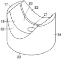
Although in the above description, use and in planar view, to be the bending slip plate 26 that ellipse roughly and integrally bending become curved shape, but rack guide 11 also alternately forms as shown in Figures 9 and 10,, as bending slip plate 26, by three layer multi-layer plates 54 are die-cut or cut into rectangle, and then as mentioned above with the same manner through by bending with draw to form thus bending slip plate 81 rectangular in planar view; Simultaneously, on an end face 17 of rack guide matrix 22, form a pair of in planar view, be half-elliptic concave surface 82 roughly and by this, be in to planar view half-elliptic concave surface 82 be roughly clipped in the middle and be formed with planar view in be the planar view rectangle concave portions 83 of the circular-arc concave surface 18 of substantially elliptical, and the bending slip plate as crooked slip plate 26 81 is equipped and be fixed to planar view rectangle concave portions 83.In addition, the rack and pinion type steering hardware 1 for use with the rack guide 11 of rack guide matrix 22, in one end 17, be provided with in pair of planar figure, to be roughly half-elliptic concave surface 82 and to be roughly half-elliptic concave surface 82 by this in to planar view and be clipped in the middle, and be formed with the planar view rectangle concave portions 83 of the circular-arc concave surface 18 in planar view, and the bending slip plate 81 that is equipped with and is fixed to the planar view rectangle concave portions 83 of rack guide matrix 22, crooked slip plate 81 is fixed to rack guide matrix 22, the tubular portion 41 of crooked slip plate 81 is press fitted in manhole 21, and the bump 43 of crooked slip plate 81 is around the other end of manhole 21 and top surface 29 pressure contacts of rack guide matrix 22, therefore, can realize advantage similar to the above.In addition,, because bending slip plate 81 is equipped and be fixed to planar view rectangular depression part 83, can realize more satisfactorily these advantages.
In addition, in the above description, on the circular-arc concave surface 23 and circular-arc convex surface 24 of bending slip plate 26, circular-arc concave surface 61 and a pair of circular-arc concave surface 62 are symmetrically formed integrally be no more than the angular range 66 of 50 ° to angle from 0 ° of angle in, contact with the circular-arc outer peripheral face 9 of rack bar 10 with respect to line of centers 65, and there is gap and be not in contact with it with the circular-arc outer peripheral face of rack bar 10 in the angular range 67 that surpasses 50 ° of angles, and circular-arc convex surface 63 and a pair of circular-arc convex surface 64 are symmetrically formed with respect to line of centers 65, have and corresponding circular-arc concave surface 61 and the large radius of curvature of the similar shape of a pair of circular-arc concave surface 62 radius of curvature corresponding to Bi Qi, and the circular-arc concave surface 18 of rack guide matrix 22 is formed by circular-arc concave surface 71 and a pair of circular-arc concave surface 72, circular-arc concave surface 71 and a pair of circular-arc concave surface 72 have with the shape of the shape complementarity of circular-arc convex surface 63 and a pair of circular-arc convex surface 64 with circular-arc convex surface 63 and a pair of circular-arc convex surface 64 close contacts.But or as shown in figure 12, the circular-arc concave surface 23 of crooked slip plate 26 can form has two circular-arc concave surfaces 85 and 86, with by partly slidably contacting with the circular-arc outer peripheral face 9 of rack bar 10 with 86 places at circular-arc concave surface 85 vertically A support movably rack bar 10, and also can form and there are two circular-arc convex surfaces 87 and 88 as the circular-arc convex surface 24 of bending slip plate 26 with thering are circular-arc concave surface 23 opposition sides (rear surface) of two circular-arc concave surfaces 85 and 86.
In the bending slip plate 26 shown in Figure 12, circular-arc concave surface 85 has the center of curvature O2 of the center of curvature O1 of the circular-arc outer peripheral face 9 that departs from rack bar 10, and there is the large radius of curvature of radius of curvature than the circular-arc outer peripheral face 9 of rack bar 10, thereby along in angle direction one side of the line of centers 65 of the center of curvature O1 through the circular-arc outer peripheral face 9 of rack bar 10 from the region of the angular range 89 of 0 ° to 90 °, in this embodiment at the circular-arc outer peripheral face 9 of the external rack bar 10 in the region 90 of 45 ° of angles.On the other hand, circular-arc concave surface 86 has the center of curvature O3 departing from from the center of curvature O1 of the circular-arc outer peripheral face 9 of rack bar 10, and there is radius of curvature larger than the radius of curvature of rack bar 10 and that equate with the radius of curvature of circular-arc concave surface 85, thereby along the angle direction of the line of centers 65 of the center of curvature O1 through the circular-arc outer peripheral face 9 of rack bar 10 region from the angular range 91 of 0 ° to 90 ° on opposite side, i.e. the circular-arc outer peripheral face 9 of the external rack bar 10 in region 92 in angle [alpha]=45 ° in this embodiment.Two circular-arc concave surfaces 85 and 86 are symmetrically formed with respect to line of centers 65, and preferably two circular-arc convex surfaces 87 and 88 have respectively and corresponding two circular-arc concave surfaces 85 and 86 similar shapes and the larger radius of curvature of Bi Qi radius of curvature.In this case, as shown in figure 12, if thereby the circular-arc concave surface 18 of rack guide matrix 22 is formed with two circular-arc concave surfaces 93 and 94 of circular-arc convex surface 87 and 88 close contacts by the corresponding circular-arc convex surface 87 of shape and crooked slip plate 26 and 88 shape complementarity, just enough.
According to embodiment illustrated in fig. 12, have advantages of above-mentioned,, crooked slip plate 26 can firmly remain on rack guide matrix 22 similarly over a long time, and can be as under initial setting up state over a long time retaining zone 90 contact with the line of crooked slip plate 26 with 92 place's rack bars 10 or shaped like narrow contact, rack bar 10 can contact with the line of crooked slip plate 26 at region 90 and 92 places or comprise that region 90 contacts and significantly reduces with near the shaped like narrow 92 with 92 region 90 due to rack bar 10 with the sliding-frictional resistance between crooked slip plate 26.
The explanation of Reference numeral
9: circular-arc outer peripheral face
10: rack bar
11: rack bar guiding piece
17: end face
18: circular-arc concave surface
19: end face
20: hollow depression part
21: manhole
22: rack guide matrix
23: circular-arc concave surface
24: circular-arc convex surface
25: protrusion
26: crooked slip plate
Claims (13)
1. a rack guide, comprising:
The rack guide matrix that synthetic resin is made, the rack guide matrix that described synthetic resin is made has the circular-arc concave surface of the one end of being arranged on, the hollow depression part that is arranged on its other end and manhole, described manhole in its one end at the core opening of described circular-arc concave surface, and at its other end at described hollow depression part opening; And crooked slip plate, described crooked slip plate have circular-arc concave surface for supporting slidably the circular-arc outer peripheral face of rack bar, with circular-arc convex surface and the tubulose protrusion of the described circular-arc concave surface close contact of described rack guide matrix, described tubulose protrusion is arranged on described circular-arc convex surface and at described circular-arc concave surface inner opening integratedly, and there is the inside of partly closing with respect to described hollow depression
Wherein said protrusion has the tubular portion being at one end arranged on integratedly on described circular-arc convex surface, closed bottom and the bump that is arranged on the other end of described tubular portion, described bump is arranged on integratedly on described tubular portion in one side, and on its opposite side, be arranged on integratedly on described closed bottom and radially outward expansion, and
When described tubular portion being press fitted in described manhole and described bump during around the other end of described manhole and described rack guide matrix pressure contact, described crooked slip plate is fixed to described rack guide matrix.
2. rack guide as claimed in claim 1, is characterized in that, described bump forms by the circular outer rim of closed bottom described in riveting when described crooked slip plate is fixed to described rack guide matrix.
3. rack guide as claimed in claim 1 or 2, it is characterized in that, thereby described crooked slip plate comprises backboard, applies and be formed on the lip-deep porous sintered metal layer of described backboard and be coated in the synthetic resin layer of filling the hole of described porous sintered metal layer on the surface of described porous sintered metal layer integratedly, and described circular-arc concave surface consists of the exposing surface of described synthetic resin layer.
4. rack guide as claimed any one in claims 1 to 3, is characterized in that, described circular-arc concave surface is substantially elliptical in planar view.
5. rack guide as claimed in claim 4, is characterized in that, described crooked slip plate is substantially elliptical in planar view, and is arranged on the described circular-arc concave surface that is substantially elliptical in planar view.
6. rack guide as claimed any one in claims 1 to 3, it is characterized in that, described rack guide matrix has pair of planar figure and is half-elliptic concave surface roughly and by this, planar view is to the planar view rectangle concave portions that half-elliptic concave surface is roughly clipped in the middle and is formed with described circular-arc concave surface on it in one end.
7. rack guide as claimed in claim 6, is characterized in that, described crooked slip plate is rectangular and equipped and be fixed to described planar view rectangle concave portions in planar view.
8. the rack guide as described in any one in claim 1 to 7, it is characterized in that, the described circular-arc concave surface of described crooked slip plate is comprised of two circular-arc concave surfaces, described two circular-arc concave surfaces are symmetrical with respect to the line of centers of the center of curvature of the described circular-arc outer peripheral face through described rack bar, thereby on the angle direction both sides of the line of centers of the center of curvature through the described circular-arc outer peripheral face of described rack bar, from 0 ° of angle, to angle, be no more than in the angular range of 50 °, each circular-arc concave surface has the center of curvature identical with the center of curvature of the described circular-arc outer peripheral face of described rack bar, and there is the radius of curvature roughly the same with the radius of curvature of the described circular-arc outer peripheral face of described rack bar, thereby contact with the described circular-arc outer peripheral face of described rack bar, and within surpassing the angular range of 50 ° of angles, described in each circular-arc concave surface have the described circular-arc outer peripheral face that departs from described rack bar center of curvature center of curvature and there is the radius of curvature of the radius of curvature of the described circular-arc outer peripheral face that is greater than described rack bar, thereby there is gap with the described circular-arc outer peripheral face of described rack bar.
9. the rack guide as described in any one in claim 1 to 7, it is characterized in that, the described circular-arc concave surface of described crooked slip plate consists of two circular-arc concave surfaces, described two circular-arc concave surfaces are symmetrical with respect to the line of centers of the center of curvature of the described circular-arc outer peripheral face through described rack bar, thereby make circular-arc concave surface described in each have the described circular-arc outer peripheral face that departs from described rack bar center of curvature center of curvature and there is the radius of curvature of the radius of curvature of the described circular-arc outer peripheral face that is greater than described rack bar, thereby in every side of the line of centers of the center of curvature through the described circular-arc outer peripheral face of described rack bar, each from two regions in the angular range of 0 ° to 90 ° contacts with the described circular-arc outer peripheral face of described rack bar respectively.
10. rack guide as claimed in claim 9, is characterized in that, described angular range is from 30 ° to 60 ° or from 30 ° to 45 °.
11. rack guides as described in any one in claim 1 to 10, it is characterized in that, described rack guide matrix is made by thermoplastic synthetic resin, and at least one dead matter in the glass fibre that described thermoplastic synthetic resin comprises 30 to 50 quality %, carbon fiber and glass powder are as reinforcing filler.
12. rack guides as claimed in claim 11, is characterized in that, described thermoplastic synthetic resin is selected from polyacetal resin, amilan, alkide resin and polyphenylene sulfide.
13. 1 kinds of rack and pinion type steering hardwares, comprising:
Gear case, described gear case has hollow space;
Miniature gears, described miniature gears is arranged on rotationally in the described hollow space of described gear case and rotates by handling maneuver;
Rack bar, described rack bar has the rack tooth with described miniature gears engagement;
Rack guide as described in any one in claim 1 to 12, described rack guide is arranged on movably in the described hollow space of described gear case and guides movably and support described rack bar; And
Springing, described springing is arranged in the described hollow space of described gear case and by means of described rack guide, the described rack tooth elasticity of described rack bar is pushed against to described miniature gears.
Applications Claiming Priority (3)
| Application Number | Priority Date | Filing Date | Title |
|---|---|---|---|
| JP2011-165933 | 2011-07-28 | ||
| JP2011165933A JP6106914B2 (en) | 2011-07-28 | 2011-07-28 | Rack guide and rack and pinion type steering apparatus provided with the rack guide |
| PCT/JP2012/004459 WO2013014870A1 (en) | 2011-07-28 | 2012-07-10 | Rack guide, and rack and pinion steering device with rack guide |
Publications (1)
| Publication Number | Publication Date |
|---|---|
| CN103702892A true CN103702892A (en) | 2014-04-02 |
Family
ID=47600748
Family Applications (1)
| Application Number | Title | Priority Date | Filing Date |
|---|---|---|---|
| CN201280036135.2A Pending CN103702892A (en) | 2011-07-28 | 2012-07-10 | Rack guide, and rack and pinion steering device with rack guide |
Country Status (5)
| Country | Link |
|---|---|
| EP (1) | EP2738065B1 (en) |
| JP (1) | JP6106914B2 (en) |
| CN (1) | CN103702892A (en) |
| BR (1) | BR112014000981A2 (en) |
| WO (1) | WO2013014870A1 (en) |
Cited By (2)
| Publication number | Priority date | Publication date | Assignee | Title |
|---|---|---|---|---|
| CN110382915A (en) * | 2017-03-16 | 2019-10-25 | 奥依列斯工业株式会社 | Rack guide and gear mechanism |
| CN112673185A (en) * | 2018-09-19 | 2021-04-16 | 奥依列斯工业株式会社 | Multi-layer sliding member and rack-and-pinion steering device for automobile using same |
Families Citing this family (2)
| Publication number | Priority date | Publication date | Assignee | Title |
|---|---|---|---|---|
| JP6661867B2 (en) * | 2014-09-24 | 2020-03-11 | 大豊工業株式会社 | Rack guide and rack and pinion type steering device provided with the rack guide |
| KR102153146B1 (en) * | 2015-10-26 | 2020-09-07 | 현대자동차주식회사 | Device for supporting rack for steering of vehicle |
Citations (9)
| Publication number | Priority date | Publication date | Assignee | Title |
|---|---|---|---|---|
| JPS5021973A (en) * | 1973-06-28 | 1975-03-08 | ||
| JPS61123430A (en) * | 1984-11-19 | 1986-06-11 | Sobi Kogei:Kk | Joining method between plate-shaped members |
| JPH07323850A (en) * | 1994-05-31 | 1995-12-12 | Oiles Ind Co Ltd | Rack-pinion type steering device |
| JPH07323851A (en) * | 1994-05-31 | 1995-12-12 | Oiles Ind Co Ltd | Rack-pinion type steering device |
| JPH1191592A (en) * | 1997-09-26 | 1999-04-06 | Daido Metal Co Ltd | Rack guide for rack-and-pinion type steering system |
| JP2000177604A (en) * | 1998-12-11 | 2000-06-27 | Oiles Ind Co Ltd | Rack and pinion type steering device |
| JP2002337702A (en) * | 2001-05-15 | 2002-11-27 | Koyo Seiko Co Ltd | Rack and pinion type steering device |
| US20050257635A1 (en) * | 2004-05-24 | 2005-11-24 | Damore Michael J | Rack yoke assembly |
| CN1930032A (en) * | 2004-03-09 | 2007-03-14 | 奥依列斯工业株式会社 | Rack guide and rack and pinion steering device using the rack guide |
Family Cites Families (8)
| Publication number | Priority date | Publication date | Assignee | Title |
|---|---|---|---|---|
| DE2402062A1 (en) * | 1974-01-17 | 1975-07-24 | Zahnradfabrik Friedrichshafen | RACK STEERING GEAR, IN PARTICULAR FOR KRFAT VEHICLES |
| JPS57174272U (en) * | 1981-04-30 | 1982-11-02 | ||
| JPS58188263U (en) * | 1982-06-04 | 1983-12-14 | 光洋精工株式会社 | Rack and pinion type steering device rack shaft support device |
| JPS60105568U (en) * | 1983-12-26 | 1985-07-18 | オイレス工業株式会社 | Rack and pinion steering device |
| JPS646382U (en) | 1987-06-30 | 1989-01-13 | ||
| JPS6427495U (en) | 1987-08-10 | 1989-02-16 | ||
| JPH0738721U (en) * | 1993-12-17 | 1995-07-14 | 市光工業株式会社 | Mounting structure for automobile parts |
| EP1508708A1 (en) * | 2003-08-22 | 2005-02-23 | Delphi Technologies, Inc. | Multi layer bearing liner for a rack guide |
-
2011
- 2011-07-28 JP JP2011165933A patent/JP6106914B2/en active Active
-
2012
- 2012-07-10 WO PCT/JP2012/004459 patent/WO2013014870A1/en active Application Filing
- 2012-07-10 EP EP12817126.1A patent/EP2738065B1/en active Active
- 2012-07-10 BR BR112014000981A patent/BR112014000981A2/en not_active Application Discontinuation
- 2012-07-10 CN CN201280036135.2A patent/CN103702892A/en active Pending
Patent Citations (9)
| Publication number | Priority date | Publication date | Assignee | Title |
|---|---|---|---|---|
| JPS5021973A (en) * | 1973-06-28 | 1975-03-08 | ||
| JPS61123430A (en) * | 1984-11-19 | 1986-06-11 | Sobi Kogei:Kk | Joining method between plate-shaped members |
| JPH07323850A (en) * | 1994-05-31 | 1995-12-12 | Oiles Ind Co Ltd | Rack-pinion type steering device |
| JPH07323851A (en) * | 1994-05-31 | 1995-12-12 | Oiles Ind Co Ltd | Rack-pinion type steering device |
| JPH1191592A (en) * | 1997-09-26 | 1999-04-06 | Daido Metal Co Ltd | Rack guide for rack-and-pinion type steering system |
| JP2000177604A (en) * | 1998-12-11 | 2000-06-27 | Oiles Ind Co Ltd | Rack and pinion type steering device |
| JP2002337702A (en) * | 2001-05-15 | 2002-11-27 | Koyo Seiko Co Ltd | Rack and pinion type steering device |
| CN1930032A (en) * | 2004-03-09 | 2007-03-14 | 奥依列斯工业株式会社 | Rack guide and rack and pinion steering device using the rack guide |
| US20050257635A1 (en) * | 2004-05-24 | 2005-11-24 | Damore Michael J | Rack yoke assembly |
Cited By (4)
| Publication number | Priority date | Publication date | Assignee | Title |
|---|---|---|---|---|
| CN110382915A (en) * | 2017-03-16 | 2019-10-25 | 奥依列斯工业株式会社 | Rack guide and gear mechanism |
| CN110382915B (en) * | 2017-03-16 | 2022-06-10 | 奥依列斯工业株式会社 | Rack guide and gear mechanism |
| CN112673185A (en) * | 2018-09-19 | 2021-04-16 | 奥依列斯工业株式会社 | Multi-layer sliding member and rack-and-pinion steering device for automobile using same |
| CN112673185B (en) * | 2018-09-19 | 2023-03-24 | 奥依列斯工业株式会社 | Multi-layer sliding member and rack-and-pinion steering device for automobile using same |
Also Published As
| Publication number | Publication date |
|---|---|
| WO2013014870A1 (en) | 2013-01-31 |
| BR112014000981A2 (en) | 2017-02-21 |
| JP2013028285A (en) | 2013-02-07 |
| EP2738065B1 (en) | 2017-11-01 |
| EP2738065A1 (en) | 2014-06-04 |
| EP2738065A4 (en) | 2015-08-26 |
| JP6106914B2 (en) | 2017-04-05 |
Similar Documents
| Publication | Publication Date | Title |
|---|---|---|
| CN103702892A (en) | Rack guide, and rack and pinion steering device with rack guide | |
| JP6314487B2 (en) | Sealing device | |
| CN106457625B (en) | Shaping dies and undercutting manufacturing process | |
| JP2008265958A (en) | Shaft for roller | |
| KR20180079362A (en) | Bending machine for forming a waveform on a metal sheet and method of using such a banding machine | |
| CN105697785A (en) | Symmetrical spring seal ring | |
| KR20190015744A (en) | Plain bearing assembly | |
| JPS6056759A (en) | Clamping device for core | |
| JP6041055B2 (en) | Manufacturing method of shell-type needle bearing and manufacturing jig used for manufacturing the same | |
| CN108602110B (en) | The manufacturing method of the spring member of sealing device | |
| JPH0127495Y2 (en) | ||
| JP2012112605A (en) | Insulation hot water storage device | |
| CN103249957B (en) | Tripod rolling element with spring ring | |
| JP4003430B2 (en) | Method of manufacturing rack guide for rack and pinion type steering device | |
| CN109654117B (en) | Bidirectional compression-resistant bearing | |
| CN209212795U (en) | A kind of ultralight circular cone pressing cage | |
| KR101801599B1 (en) | Resin cage | |
| JP4145744B2 (en) | Metal corrugated sheet manufacturing method | |
| JPH08133099A (en) | Pack guide for pack pinion type steering system and manufacture thereof | |
| JP2000168577A (en) | Manufacture of rack guide of rack-and-pinion type steering device, and pack-and-pinion type steering device equipped with the rack guide | |
| JPH07323850A (en) | Rack-pinion type steering device | |
| CN213559513U (en) | Roller bending die | |
| JP7074947B2 (en) | chain | |
| CN209158732U (en) | A kind of convenient assembling press ball-type workbench | |
| JP4624267B2 (en) | Thrust bearing |
Legal Events
| Date | Code | Title | Description |
|---|---|---|---|
| C06 | Publication | ||
| PB01 | Publication | ||
| C10 | Entry into substantive examination | ||
| SE01 | Entry into force of request for substantive examination | ||
| RJ01 | Rejection of invention patent application after publication | ||
| RJ01 | Rejection of invention patent application after publication |
Application publication date: 20140402 |