KR20190015744A - Plain bearing assembly - Google Patents
Plain bearing assembly Download PDFInfo
- Publication number
- KR20190015744A KR20190015744A KR1020197000044A KR20197000044A KR20190015744A KR 20190015744 A KR20190015744 A KR 20190015744A KR 1020197000044 A KR1020197000044 A KR 1020197000044A KR 20197000044 A KR20197000044 A KR 20197000044A KR 20190015744 A KR20190015744 A KR 20190015744A
- Authority
- KR
- South Korea
- Prior art keywords
- component
- feature
- axial end
- generally cylindrical
- bearing
- Prior art date
Links
Images


Classifications
-
- F—MECHANICAL ENGINEERING; LIGHTING; HEATING; WEAPONS; BLASTING
- F16—ENGINEERING ELEMENTS AND UNITS; GENERAL MEASURES FOR PRODUCING AND MAINTAINING EFFECTIVE FUNCTIONING OF MACHINES OR INSTALLATIONS; THERMAL INSULATION IN GENERAL
- F16C—SHAFTS; FLEXIBLE SHAFTS; ELEMENTS OR CRANKSHAFT MECHANISMS; ROTARY BODIES OTHER THAN GEARING ELEMENTS; BEARINGS
- F16C17/00—Sliding-contact bearings for exclusively rotary movement
- F16C17/04—Sliding-contact bearings for exclusively rotary movement for axial load only
-
- B—PERFORMING OPERATIONS; TRANSPORTING
- B21—MECHANICAL METAL-WORKING WITHOUT ESSENTIALLY REMOVING MATERIAL; PUNCHING METAL
- B21D—WORKING OR PROCESSING OF SHEET METAL OR METAL TUBES, RODS OR PROFILES WITHOUT ESSENTIALLY REMOVING MATERIAL; PUNCHING METAL
- B21D53/00—Making other particular articles
- B21D53/10—Making other particular articles parts of bearings; sleeves; valve seats or the like
-
- F—MECHANICAL ENGINEERING; LIGHTING; HEATING; WEAPONS; BLASTING
- F16—ENGINEERING ELEMENTS AND UNITS; GENERAL MEASURES FOR PRODUCING AND MAINTAINING EFFECTIVE FUNCTIONING OF MACHINES OR INSTALLATIONS; THERMAL INSULATION IN GENERAL
- F16C—SHAFTS; FLEXIBLE SHAFTS; ELEMENTS OR CRANKSHAFT MECHANISMS; ROTARY BODIES OTHER THAN GEARING ELEMENTS; BEARINGS
- F16C11/00—Pivots; Pivotal connections
- F16C11/02—Trunnions; Crank-pins
-
- F—MECHANICAL ENGINEERING; LIGHTING; HEATING; WEAPONS; BLASTING
- F16—ENGINEERING ELEMENTS AND UNITS; GENERAL MEASURES FOR PRODUCING AND MAINTAINING EFFECTIVE FUNCTIONING OF MACHINES OR INSTALLATIONS; THERMAL INSULATION IN GENERAL
- F16C—SHAFTS; FLEXIBLE SHAFTS; ELEMENTS OR CRANKSHAFT MECHANISMS; ROTARY BODIES OTHER THAN GEARING ELEMENTS; BEARINGS
- F16C17/00—Sliding-contact bearings for exclusively rotary movement
- F16C17/10—Sliding-contact bearings for exclusively rotary movement for both radial and axial load
-
- F—MECHANICAL ENGINEERING; LIGHTING; HEATING; WEAPONS; BLASTING
- F16—ENGINEERING ELEMENTS AND UNITS; GENERAL MEASURES FOR PRODUCING AND MAINTAINING EFFECTIVE FUNCTIONING OF MACHINES OR INSTALLATIONS; THERMAL INSULATION IN GENERAL
- F16C—SHAFTS; FLEXIBLE SHAFTS; ELEMENTS OR CRANKSHAFT MECHANISMS; ROTARY BODIES OTHER THAN GEARING ELEMENTS; BEARINGS
- F16C33/00—Parts of bearings; Special methods for making bearings or parts thereof
- F16C33/02—Parts of sliding-contact bearings
- F16C33/04—Brasses; Bushes; Linings
- F16C33/06—Sliding surface mainly made of metal
- F16C33/12—Structural composition; Use of special materials or surface treatments, e.g. for rust-proofing
- F16C33/122—Multilayer structures of sleeves, washers or liners
- F16C33/124—Details of overlays
-
- F—MECHANICAL ENGINEERING; LIGHTING; HEATING; WEAPONS; BLASTING
- F16—ENGINEERING ELEMENTS AND UNITS; GENERAL MEASURES FOR PRODUCING AND MAINTAINING EFFECTIVE FUNCTIONING OF MACHINES OR INSTALLATIONS; THERMAL INSULATION IN GENERAL
- F16C—SHAFTS; FLEXIBLE SHAFTS; ELEMENTS OR CRANKSHAFT MECHANISMS; ROTARY BODIES OTHER THAN GEARING ELEMENTS; BEARINGS
- F16C33/00—Parts of bearings; Special methods for making bearings or parts thereof
- F16C33/02—Parts of sliding-contact bearings
- F16C33/04—Brasses; Bushes; Linings
- F16C33/06—Sliding surface mainly made of metal
- F16C33/12—Structural composition; Use of special materials or surface treatments, e.g. for rust-proofing
- F16C33/122—Multilayer structures of sleeves, washers or liners
- F16C33/125—Details of bearing layers, i.e. the lining
-
- F—MECHANICAL ENGINEERING; LIGHTING; HEATING; WEAPONS; BLASTING
- F16—ENGINEERING ELEMENTS AND UNITS; GENERAL MEASURES FOR PRODUCING AND MAINTAINING EFFECTIVE FUNCTIONING OF MACHINES OR INSTALLATIONS; THERMAL INSULATION IN GENERAL
- F16C—SHAFTS; FLEXIBLE SHAFTS; ELEMENTS OR CRANKSHAFT MECHANISMS; ROTARY BODIES OTHER THAN GEARING ELEMENTS; BEARINGS
- F16C33/00—Parts of bearings; Special methods for making bearings or parts thereof
- F16C33/02—Parts of sliding-contact bearings
- F16C33/04—Brasses; Bushes; Linings
- F16C33/06—Sliding surface mainly made of metal
- F16C33/14—Special methods of manufacture; Running-in
-
- F—MECHANICAL ENGINEERING; LIGHTING; HEATING; WEAPONS; BLASTING
- F16—ENGINEERING ELEMENTS AND UNITS; GENERAL MEASURES FOR PRODUCING AND MAINTAINING EFFECTIVE FUNCTIONING OF MACHINES OR INSTALLATIONS; THERMAL INSULATION IN GENERAL
- F16C—SHAFTS; FLEXIBLE SHAFTS; ELEMENTS OR CRANKSHAFT MECHANISMS; ROTARY BODIES OTHER THAN GEARING ELEMENTS; BEARINGS
- F16C33/00—Parts of bearings; Special methods for making bearings or parts thereof
- F16C33/02—Parts of sliding-contact bearings
- F16C33/04—Brasses; Bushes; Linings
- F16C33/20—Sliding surface consisting mainly of plastics
- F16C33/203—Multilayer structures, e.g. sleeves comprising a plastic lining
- F16C33/205—Multilayer structures, e.g. sleeves comprising a plastic lining with two layers
-
- F—MECHANICAL ENGINEERING; LIGHTING; HEATING; WEAPONS; BLASTING
- F16—ENGINEERING ELEMENTS AND UNITS; GENERAL MEASURES FOR PRODUCING AND MAINTAINING EFFECTIVE FUNCTIONING OF MACHINES OR INSTALLATIONS; THERMAL INSULATION IN GENERAL
- F16C—SHAFTS; FLEXIBLE SHAFTS; ELEMENTS OR CRANKSHAFT MECHANISMS; ROTARY BODIES OTHER THAN GEARING ELEMENTS; BEARINGS
- F16C33/00—Parts of bearings; Special methods for making bearings or parts thereof
- F16C33/02—Parts of sliding-contact bearings
- F16C33/04—Brasses; Bushes; Linings
- F16C33/20—Sliding surface consisting mainly of plastics
- F16C33/208—Methods of manufacture, e.g. shaping, applying coatings
-
- F—MECHANICAL ENGINEERING; LIGHTING; HEATING; WEAPONS; BLASTING
- F16—ENGINEERING ELEMENTS AND UNITS; GENERAL MEASURES FOR PRODUCING AND MAINTAINING EFFECTIVE FUNCTIONING OF MACHINES OR INSTALLATIONS; THERMAL INSULATION IN GENERAL
- F16C—SHAFTS; FLEXIBLE SHAFTS; ELEMENTS OR CRANKSHAFT MECHANISMS; ROTARY BODIES OTHER THAN GEARING ELEMENTS; BEARINGS
- F16C35/00—Rigid support of bearing units; Housings, e.g. caps, covers
- F16C35/02—Rigid support of bearing units; Housings, e.g. caps, covers in the case of sliding-contact bearings
-
- F—MECHANICAL ENGINEERING; LIGHTING; HEATING; WEAPONS; BLASTING
- F16—ENGINEERING ELEMENTS AND UNITS; GENERAL MEASURES FOR PRODUCING AND MAINTAINING EFFECTIVE FUNCTIONING OF MACHINES OR INSTALLATIONS; THERMAL INSULATION IN GENERAL
- F16C—SHAFTS; FLEXIBLE SHAFTS; ELEMENTS OR CRANKSHAFT MECHANISMS; ROTARY BODIES OTHER THAN GEARING ELEMENTS; BEARINGS
- F16C2208/00—Plastics; Synthetic resins, e.g. rubbers
- F16C2208/02—Plastics; Synthetic resins, e.g. rubbers comprising fillers, fibres
-
- F—MECHANICAL ENGINEERING; LIGHTING; HEATING; WEAPONS; BLASTING
- F16—ENGINEERING ELEMENTS AND UNITS; GENERAL MEASURES FOR PRODUCING AND MAINTAINING EFFECTIVE FUNCTIONING OF MACHINES OR INSTALLATIONS; THERMAL INSULATION IN GENERAL
- F16C—SHAFTS; FLEXIBLE SHAFTS; ELEMENTS OR CRANKSHAFT MECHANISMS; ROTARY BODIES OTHER THAN GEARING ELEMENTS; BEARINGS
- F16C2223/00—Surface treatments; Hardening; Coating
- F16C2223/30—Coating surfaces
- F16C2223/32—Coating surfaces by attaching pre-existing layers, e.g. resin sheets or foils by adhesion to a substrate; Laminating
-
- F—MECHANICAL ENGINEERING; LIGHTING; HEATING; WEAPONS; BLASTING
- F16—ENGINEERING ELEMENTS AND UNITS; GENERAL MEASURES FOR PRODUCING AND MAINTAINING EFFECTIVE FUNCTIONING OF MACHINES OR INSTALLATIONS; THERMAL INSULATION IN GENERAL
- F16C—SHAFTS; FLEXIBLE SHAFTS; ELEMENTS OR CRANKSHAFT MECHANISMS; ROTARY BODIES OTHER THAN GEARING ELEMENTS; BEARINGS
- F16C2240/00—Specified values or numerical ranges of parameters; Relations between them
- F16C2240/40—Linear dimensions, e.g. length, radius, thickness, gap
- F16C2240/60—Thickness, e.g. thickness of coatings
-
- F—MECHANICAL ENGINEERING; LIGHTING; HEATING; WEAPONS; BLASTING
- F16—ENGINEERING ELEMENTS AND UNITS; GENERAL MEASURES FOR PRODUCING AND MAINTAINING EFFECTIVE FUNCTIONING OF MACHINES OR INSTALLATIONS; THERMAL INSULATION IN GENERAL
- F16C—SHAFTS; FLEXIBLE SHAFTS; ELEMENTS OR CRANKSHAFT MECHANISMS; ROTARY BODIES OTHER THAN GEARING ELEMENTS; BEARINGS
- F16C2240/00—Specified values or numerical ranges of parameters; Relations between them
- F16C2240/40—Linear dimensions, e.g. length, radius, thickness, gap
- F16C2240/70—Diameters; Radii
-
- F—MECHANICAL ENGINEERING; LIGHTING; HEATING; WEAPONS; BLASTING
- F16—ENGINEERING ELEMENTS AND UNITS; GENERAL MEASURES FOR PRODUCING AND MAINTAINING EFFECTIVE FUNCTIONING OF MACHINES OR INSTALLATIONS; THERMAL INSULATION IN GENERAL
- F16C—SHAFTS; FLEXIBLE SHAFTS; ELEMENTS OR CRANKSHAFT MECHANISMS; ROTARY BODIES OTHER THAN GEARING ELEMENTS; BEARINGS
- F16C2300/00—Application independent of particular apparatuses
- F16C2300/02—General use or purpose, i.e. no use, purpose, special adaptation or modification indicated or a wide variety of uses mentioned
Abstract
일 실시 예에서, 베어링은 두께 tSW를 갖는 대체로 원통형인 측벽; 상기 대체로 원통형인 측벽으로부터 방사상 외측으로 돌출하여 원주 방향으로 연장되는 피처로서, 적어도 약 2.0 tSW의 축 방향 높이를 갖는, 상기 원주 방향으로 연장되는 피처; 및 상기 대체로 원통형인 측벽의 축 방향 단부에 배치되고 상기 원주 방향으로 연장되는 피처로부터 이격되는 플랜지(flange)를 포함한다. 다른 실시 예에서는, 어셈블리가 개구를 포함하는 제1 구성요소; 상기 제1 구성요소에 대해 동축인 제2 구성요소; 및 상기 제1 구성요소와 상기 제2 구성요소 사이에 축 방향으로 배치되고 상기 제1 구성요소의 상기 개구 내에 적어도 부분적으로 배치되는 베어링을 포함하되, 상기 제1 구성요소 및 상기 제2 구성요소는 서로 거리(D)만큼 이격되고, 상기 베어링은 측면도로부터 상기 거리(D) 전체를 따라 보일 수 있다.In one embodiment, the bearing has a generally cylindrical sidewall having a thickness t SW ; A circumferentially extending feature radially outwardly projecting from said generally cylindrical sidewall, said circumferentially extending feature having an axial height of at least about 2.0 t SW ; And a flange disposed at an axial end of the generally cylindrical sidewall and spaced from the circumferentially extending feature. In another embodiment, the assembly includes a first component comprising an aperture; A second component that is coaxial with respect to the first component; And a bearing axially disposed between the first component and the second component and at least partially disposed within the opening of the first component, wherein the first component and the second component Are spaced apart from each other by a distance D, and the bearing can be seen from the side view along the entire distance D thereof.
Description
본 발명은 베어링들에 관한 것으로, 보다 상세하게는 평 베어링들(plain bearings)에 관한 것이다.The present invention relates to bearings, and more particularly to plain bearings.
베어링들은 통상적으로 다수의 구성요소를 서로 회전, 피봇 또는 미끄럼 가능하게 고정하기위해 어셈블리들에 사용된다. 베어링들은 일반적으로 움직이는 부분들 사이의 마찰을 줄여, 다른 방법으로 이룰 수 있는 것보다 효율적인 에너지 수송을 가능하게 한다. 베어링들을 이용하는 산업들은 계속해서 베어링 성능 향상과 베어링들이 상이한 환경들에서 작동할 수 있을 것을 필요로 한다.Bearings are typically used in assemblies to rotate, pivot, or slidably lock multiple components together. Bearings generally reduce friction between moving parts, enabling more efficient energy transport than can be achieved by other methods. Industries using bearings continue to require increased bearing performance and bearings to be able to operate in different environments.
실시 예들은 예로서 예시되고 첨부 도면들에 제한되지 않는다.
도 1은 일 실시 예에 따른 베어링의 사시도를 포함한다.
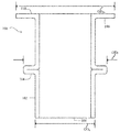
도 2는 라인 A-A에 따라 보여지는 도 1의 베어링의 측단면도를 포함한다.
도 3은 다른 실시 예에 따른 베어링의 측면도를 포함한다.
도 4는 일 실시 예에 따른 베어링을 포함하는 어셈블리의 측단면도를 포함한다.
도 5는 판재의 사시도를 포함한다.
도 6은 도 5에서의 라인 B-B에 따라 보여지는 판재의 측단면도를 포함한다.
도 7은 판재로부터 블랭크를 형성하는 단계의 사시도를 포함한다.
도 8은 베어링의 대체로 원통형인 측벽을 형성하기 전후의 블랭크의 상면도를 포함한다.
도 9는 플랜지 및 피처의 형성 이전, 도중 및 이후 라인 C-C에 따라 보여지는 베어링의 측단면도를 포함한다.
도 10은 다른 실시 예에 따른 어셈블리의 측단면도를 포함한다.
통상의 기술자들은 도면들에서의 요소들이 단순하고 명료하게 도시되고 반드시 일정한 비율로 그려진 것은 아님을 이해한다. 예를 들어, 도면들에서의 요소들 중 일부 요소의 치수들은 본 발명의 실시 예들에 대한 이해를 향상시키는 것을 돕기 위해 다른 요소들에 비해 확대될 수 있다.The embodiments are illustrated by way of example and are not limited to the accompanying drawings.
Figure 1 includes a perspective view of a bearing according to one embodiment.
Figure 2 includes a side cross-sectional view of the bearing of Figure 1 shown along line AA.
Figure 3 includes a side view of a bearing according to another embodiment.
Figure 4 includes a side cross-sectional view of an assembly including a bearing according to one embodiment.
5 includes a perspective view of the plate material.
Fig. 6 includes a side cross-sectional view of the plate shown in accordance with line BB in Fig.
Figure 7 includes a perspective view of the step of forming a blank from the sheet material.
Figure 8 includes a top view of the blank before and after forming the generally cylindrical sidewalls of the bearing.
Figure 9 includes a side cross-sectional view of the bearing shown in accordance with line CC before, during and after the formation of the flanges and features.
10 includes a side cross-sectional view of an assembly according to another embodiment.
Those of ordinary skill in the art understand that the elements in the figures are shown in a simple and clear manner and are not necessarily drawn to scale. For example, the dimensions of some of the elements in the figures may be enlarged relative to other elements to help improve understanding of embodiments of the present invention.
이하의 설명은 도면들과 함께 본 출원에 개시된 교시 내용을 이해하는 것을 돕기 위해 제공된다. 이하의 논의는 본 교시 내용의 특정 구현 예들 및 실시 예들에 포커스를 맞출 것이다. 이러한 포커스는 본 교시 내용을 설명하는 것을 돕기 위해 제공되는 것이고 본 교시 내용의 범위 또는 응용 가능성에 관한 제한으로 해석되지 않아야 한다.BRIEF DESCRIPTION OF THE DRAWINGS The following description, together with the drawings, is provided to assist in understanding the teachings of the present application. The following discussion will focus on particular implementations and embodiments of the present teachings. These focuses are provided to help illustrate this teaching and should not be construed as limiting the scope or applicability of this teaching.
본 출원에서 사용될 때, "포함한다(comprises)", "포함하는(comprising)", "포함하다(includes)", "포함한(including)", "갖는다(has)", "갖는(having)"이라는 용어들 또는 이들의 임의의 다른 어미 변화는 비-배타적인 포함을 망라하도록 의도된다. 예를 들어, 피처들의 리스트를 포함하는 프로세스, 방법, 물품 또는 장치는 반드시 그러한 피처들에만 제한되는 것이 아니라 명시적으로 나열되지 않거나 그러한 프로세스, 방법, 물품 또는 장치에 내재하는 다른 피처들도 포함할 수 있다. 나아가, 명시적으로 반대로 언급되지 않는 한, "또는"은 배타적 논리합이 아니라 포함적 논리합을 나타낸다.As used in this application, the terms "comprises," "includes," "includes," "has," "having," " Quot; or " other " or " other " are intended to encompass a non-exclusive inclusion. For example, a process, method, article, or apparatus that comprises a list of features is not necessarily limited to such features, but may include other features not explicitly listed or inherent to such process, method, article, or apparatus . Furthermore, unless explicitly stated to the contrary, " or " refers to an inclusive logical OR rather than an exclusive OR.
예를 들어, 조건 A 또는 B는 다음 중 어느 하나에 의해 충족된다: A가 참(또는 존재)이고 B가 거짓(또는 부존재), A는 거짓(또는 부존재)이고 B가 참(또는 존재), 그리고 A 및 B가 모두 참(또는 존재).For example, condition A or B is satisfied by either: A is true (or exists) and B is false (or absent), A is false (or absent) and B is true And both A and B are true (or present).
"하나의(a)" 또는 "한(an)"의 사용은 본 출원에 설명된 요소들 및 구성요소들을 기술하기 위해 채용된다. 이는 단지 편의를 위해 그리고 본 발명의 범위의 일반적 의미를 제공하기 위해 이루어진다. 이러한 기술은 그것이 다르게 의도되는 것이 분명하지 않는 한, 하나 또는 적어도 하나를 포함하는 것으로 그리고 단수형이 복수형도 포함하거나, 그 반대로도 읽혀져야 한다.The use of "a" or "an" is employed to describe the elements and components described in this application. This is done merely for convenience and to provide a general sense of the scope of the invention. These techniques are to be understood as including one or at least one, and singular forms including plural, or vice versa, unless the context clearly dictates otherwise.
다르게 정의되지 않는 한, 본 출원에 사용되는 모든 기술적 그리고 과학적 용어는 본 발명이 속하는 기술분야의 통상의 기술자에 의해 공통적으로 이해되는 바와 동일한 의미를 갖는다. 물질들, 방법들, 및 예들은 단지 예시적인 것이고 제한적인 것으로 의도되지 않는다. 특정 물질들 및 프로세싱 작업들에 관한 많은 세부 사항은 통상적인 것이고 베어링 분야 내 교재들 및 다른 자료들에서 찾아볼 수 있는 결과로, 본 출원에서는 설명되지 않는다.Unless otherwise defined, all technical and scientific terms used herein have the same meaning as commonly understood by one of ordinary skill in the art to which this invention belongs. The materials, methods, and examples are illustrative only and are not intended to be limiting. Much of the details regarding specific materials and processing operations are common and can be found in textbooks and other materials in the bearing field and are not described in the present application.
본 출원에 설명된 실시 예들 중 하나 이상의 실시 예에 따른 베어링은 일반적으로 측벽, 상기 측벽으로부터 방사상으로 돌출하는 피처, 및 상기 측벽의 축 방향 단부에 배치되는 플랜지를 포함할 수 있다. 일 실시 예에서, 상기 피처는 상기 측벽으로부터 방사상 외측으로 돌출한다. 다른 실시 예에서, 상기 피처는 상기 측벽으로부터 방사상 내측으로 돌출한다. 상기 피처는 상기 플랜지로부터 축 방향 거리(D)만큼 축 방향으로 이격될 수 있으며, 상기 베어링에 체결되는 두 개의 구성요소 사이에 소정의 간격을 허용한다.A bearing according to one or more embodiments of the embodiments described herein may generally include a sidewall, a feature radially projecting from the sidewall, and a flange disposed at an axial end of the sidewall. In one embodiment, the features project radially outwardly from the side wall. In another embodiment, the feature projects radially inward from the sidewall. The features may be axially spaced from the flange by an axial distance D and allow a predetermined spacing between the two components fastened to the bearing.
도 1은 측벽(102), 피처(feature)(104) 및 플랜지(flange)(106)를 포함하는 베어링(100)을 도시한다. 측벽(102)은 대체로 원통형일 수 있으며, 베어링(100)의 대향하는 축 방향 단부들(108 및 110) 사이에서 연장되는 개구를 획정한다. 본 출원에서 사용될 때, "대체로 원통형인 측벽"은 축 방향 단부들이 막힐 때, 최적합 원통형의 적어도 80%, 최적합 원통형의 적어도 95%, 또는 최적합 원통형의 적어도 99%를 차지하는 두 개의 축 방향 단부 및 축 방향 길이를 갖는 측벽을 지칭한다. 일 실시 예에서, 베어링(100)은 아래에서 보다 상세히 설명되는 바와 같이, 단일 판재로 형성될 수 있다.1 illustrates a
피처(104)는 측벽(102)의 적어도 일부분 주위로 연장될 수 있고 측벽(102)의 축 방향 단부들(108 및 110)로부터 이격된다. 일 실시 예에서, 피처(104)는 측벽(102) 둘레의 적어도 10%, 측벽(102) 둘레의 적어도 25%, 측벽(102) 둘레의 적어도 75%, 또는 측벽(102) 둘레의 적어도 99% 주위로 연장된다. 구체적인 실시 예에서, 피처(104)는 측벽(102)의 전체 둘레(즉, 100 %) 주위로 연속적으로 연장된다. 피처(104)는 릿지(ridge), 딤플(dimple), 돌출, 타인(tine), 또는 임의의 다른 방사상으로 연장되는 피처를 포함할 수 있다. 일 실시 예에서, 피처(104)는 측벽(102) 둘레의 적어도 일부분 주위로 연장되는 단지 하나의 방사상으로 연장되는 피처를 포함한다. 다른 실시 예에서, 피처(104)는 측벽(102) 둘레 주위로 서로 이격되는 복수의 방사상으로 연장되는 피처를 포함한다. 구체적인 실시 예에서, 복수의 방사상으로 연장되는 피처는 베어링(100)의 중심 축(112)에 대체로 수직이고 베어링(100) 둘레 주위로 연장되는 선을 따라 연장될 수 있다. 다른 구체적인 실시 예에서, 복수의 피처는 등간격으로 이격될 수 있다. 또 다른 구체적인 실시 예에서, 복수의 피처는 제1 피처 세트의 두 피처 사이 거리가 제2 피처 세트의 두 피처 사이 거리와 상이하도록 불균일하게 이격될 수 있다.The
플랜지(106)는 측벽(102)의 축 방향 단부들(108 또는 110) 중 하나에서 측벽(102)의 적어도 일부분 주위로 연장한다. 일 실시 예에서, 플랜지(106)는 측벽(102) 둘레의 적어도 10%, 측벽(102) 둘레의 적어도 25%, 측벽(102) 둘레의 적어도 75%, 또는 측벽(102) 둘레의 적어도 99% 주위로 연장된다. 구체적인 실시 예에서, 플랜지(106)는 측벽(102)의 전체(예를 들어, 100 %) 둘레 주위로 연장된다. 위에서 설명된 피처(104)와 유사하게, 플랜지(106)는 측벽(102) 둘레의 적어도 일부분 주위로 연장되는 하나의 방사상으로 연장되는 플랜지를 포함할 수 있다. 다른 실시 예에서, 플랜지(106)는 측벽(102)으로부터 방사상으로 연장되는 복수의 개별 플랜지 부분을 포함할 수 있다. 개별 플랜지 부분들은 서로 원주 방향으로 이격될 수 있다. 개별 플랜지 부분들은 모두 중심 축(112)에 대해 동일한 상대 각도를 공유하거나 상이한 상대 각도들을 가질 수 있다. 구체적인 실시 예에서, 개별 플랜지 부분들은 동등하게 이격될 수 있다. 다른 구체적인 실시 예에서, 개별 플랜지 부분들은 제1 세트의 플랜지 부분의 두 개별 플랜지 부분 사이 거리가 제2 세트의 플랜지 부분의 두 개별 플랜지 부분 사이 거리와 상이하도록 불균일하게 이격될 수 있다.The
일 실시 예에서, 피처(104) 및 플랜지(106)는 측벽(102) 주위로 동일한 원주 방향 거리만큼 연장될 수 있다. 예를 들어, 피처(104) 및 플랜지(106)는 모두 측벽(102)의 원주 길이의 100% 주위로 연장될 수 있다. 다른 예에서, 피처(104) 및 플랜지(106)는 측벽(102)의 원주 길이의 50% 주위로, 측벽(102)의 원주 길이의 75% 주위로 또는 그에 따른 임의의 다른 적절한 원주 거리로 연장될 수 있다. 다른 실시 예에서, 피처(104) 및 플랜지(106)는 측벽(102) 주위로 상이한 원주 방향 거리만큼 연장될 수 있다. 즉, 피처(104) 및 플랜지(106)는 서로에 대하여 상이한 원주 길이들을 가질 수 있다. 예를 들어, 피처(104)는 측벽(102) 둘레의 50% 주위로 연장될 수 있고 플랜지(106)는 측벽(102) 둘레의 75% 주위로 연장될 수 있거나, 또는 피처(104)는 측벽(102) 둘레의 60% 주위로 연장될 수 있고 플랜지(106)는 측벽(102) 둘레의 40% 주위로 연장될 수 있다.In one embodiment, the
도 2를 참조하면, 일 실시 예에서, 피처(104)는 측벽(102)의 최외곽 직경(ODS)보다 큰 최외곽 직경(ODF)을 가질 수 있다. 구체적인 실시 예에서, ODF는 적어도 1.01 ODS, 적어도 1.05 ODS, 적어도 1.1 ODS, 또는 적어도 1.25 ODS일 수 있다. 다른 실시 예, ODF는 3.0 ODS 이하, 2.0 ODS 이하, 또는 1,5 ODS 이하일 수 있다. 추가 실시 예에서, ODF는 1.01 ODS 내지 3.0 ODS를 포함하는 범위 내, 1.01 ODS 내지 2.0 ODS를 포함하는 범위 내, 또는 1.01 ODS 내지 1.5 ODS를 포함하는 범위 내에 있을 수 있다. 구체적인 실시 예에서, ODF는 적어도 0.1 mm, 적어도 1 mm, 적어도 5 mm, 적어도 10 mm, 적어도 20 mm, 적어도 50 mm, 적어도 75 mm, 적어도 100 mm, 또는 적어도 150 mm이다. 다른 실시 예에서, ODF는 1000 mm 이하이다.2, in one embodiment, the
일 실시 예에서, 플랜지(106)는 측벽(102)의 최외곽 직경(ODS)과 상이한 최외곽 직경(ODFL)을 가질 수 있다. 구체적인 실시 예에서, ODFL은 적어도 1.01 ODS, 적어도 1.05 ODS, 적어도 1.1 ODS, 또는 적어도 1.25 ODS일 수 있다. 다른 실시 예에서, ODFL은 5.0 ODS 이하, 3.0 ODS 이하, 또는 2.0 ODS 이하일 수 있다. 추가 실시 예에서, ODFL은 1.01 ODS 내지 5.0 ODS를 포함하는 범위 내, 1.01 ODS 내지 3.0 ODS를 포함하는 범위 내, 또는 1.01 ODS 내지 2.0 ODS를 포함하는 범위 내에 있을 수 있다. 구체적인 실시 예에서, ODFL은 적어도 0.1 mm, 적어도 1 mm, 적어도 5 mm, 적어도 10 mm, 적어도 20 mm, 적어도 50 mm, 적어도 75 mm, 적어도 100 mm, 또는 적어도 150 mm이다. 다른 실시 예에서, ODFL은 1000 mm 이하이다.In one embodiment, the
일 실시 예에서, 피처(104) 및 플랜지(106)는 측벽(102)으로부터 동일한 방사상 거리만큼 연장될 수 있다. 다른 실시 예에서, 피처(104) 및 플랜지(106)는 측벽(102)으로부터 상이한 방사상 거리들만큼 연장될 수 있다. 예를 들어, 플랜지(106)가 피처(104)보다 측벽(102)으로부터 더 큰 방사상 거리만큼 연장될 수 있다. 도 2에 도시된 바와 같이, 플랜지(106)의 최외곽 직경(ODFL)은 피처(104)의 최외곽 직경(ODF)보다 크다. 일 실시 예에서, ODFL은 적어도 1.01 ODF, 적어도 1.05 ODF, 적어도 1.1 ODF, 적어도 1.25 ODF, 또는 적어도 1.5 ODF일 수 있다. 다른 실시 예에서, ODFL은 3.0 ODF 이하, 2.5 ODF 이하, 또는 2.0 ODF 이하, 또는 1.75 ODF 이하일 수 있다. 또한, 일 실시 예에서, ODFL은 1.01 ODF 내지 3.0 ODF를 포함하는 범위에 있을 수 있다. 일 실시 예에서, ODFL은 ODF 50% 이내, ODF 40% 이내, ODF 30% 이내, ODF 20% 이내, 또는 ODF 10% 이내이다. 그에 따라, 예를 들어, ODFL이 20 mm인 실시 예는 10 mm 내지 30 mm의 ODF를 가질 수 있다.In one embodiment, the
다른 실시 예에서, ODFL은 ODF 미만일 수 있다. 예를 들어, ODFL은 0.99 ODF 이하, 0.95 ODF 이하, 또는 0.75 ODF 이하일 수 있다. 일 실시 예에서, ODFL은 0.25 ODF 이상, 0.5 ODF 이상, 또는 0.7 ODF 이상일 수 있다. ODS , ODF 와 ODFL 사이 적절한 비율들을 결정할 때 몇 가지 요인을 고려할 수 있다. 예를 들어, 적재력, 치수 공차, 마찰 요건 및 하우징 크기 제한이 ODS, ODF, 및 ODFL의 요인이 될 수 있다.In another embodiment, OD FL may be less than OD F. For example, OD FL may be below 0.99 OD F, below 0.95 OD F , or below 0.75 OD F. In one embodiment, OD FL may be greater than 0.25 OD F, greater than 0.5 OD F , or greater than 0.7 OD F. Several factors can be considered when determining the appropriate ratios between OD S , OD F and OD FL . For example, enforceability, dimensional tolerances, friction requirements, and housing size limits can be factors for OD S , OD F , and OD FL .
도 3은 내측으로 연장되는 플랜지(306) 및 내측으로 연장되는 피처(304)를 갖는 베어링(300)을 도시한다. 일 실시 예에서, 측벽(302)의 최내측 직경(IDS)보다 작은 피처(304)는 최내측 직경(IDF)을 갖는다. 구체적인 실시 예에서, IDF는 0.99 IDS 미만, 0.95 IDS 미만, 0.9 IDS 미만, 또는 0.75 IDS 미만일 수 있다. 다른 실시 예에서, IDF는 0.1 IDS 초과, 0.2 IDS 초과, 또는 0.4 IDS 초과이다. 추가 실시 예에서, IDF는 0.1 IDS 내지 0.99 IDS를 포함하는 범위 내, 0.25 IDS 내지 0.99 IDS를 포함하는 범위 내, 또는 0.5 IDS 내지 0.95 IDS를 포함하는 범위 내일 수 있다.FIG. 3 illustrates a
일 실시 예에서, 플랜지(306)는 측벽(302)의 최내측 직경(IDS)보다 작은 최내측 직경(IDFL)을 갖는다. 구체적인 실시 예에서, IDFL은 0.99 IDS 미만, 0.95 IDS 미만, 0.9 IDS 미만, 또는 0.75 IDS 미만일 수 있다. 다른 실시 예에서, IDFL은 0.1 IDS 초과, 0.2 IDS 초과, 또는 0.4 IDS 초과이다. 추가 실시 예에서, IDFL은 0.1 IDS 내지 0.99 IDS를 포함하는 범위 내, 0.25 IDS 내지 0.99 IDS를 포함하는 범위 내, 또는 0.5 IDS 내지 0.95 IDS를 포함하는 범위 내일 수 있다.In one embodiment, the
일 실시 예에서, 피처(304) 및 플랜지(306)는 측벽(302)으로부터 동일한 방사상 거리만큼 연장될 수 있다. 다른 실시 예에서, 피처(304) 및 플랜지(306)는 측벽(302)으로부터 상이한 방사상 거리들만큼 연장될 수 있다. 예를 들어, 플랜지(306)가 피처(304)보다 측벽(302)으로부터 더 큰 방사상 거리만큼 연장될 수 있다. 도 3에 도시된 바와 같이, 플랜지(306)의 최내측 직경(IDFL)은 피처(304)의 최내측 직경(IDF)보다 작다. 일 실시 예에서, IDFL은 0.99 IDF 이하, 0.9 IDF 이하, 또는 0.75 IDF 이하일 수 있다. 다른 실시 예에서, IDFL은 0.25 IDF 이상, 0.5 IDF 이상, 또는 0.7 IDF 이상일 수 있다.In one embodiment, feature 304 and
도시되지 않은 실시 예에서, 베어링의 피처 및 플랜지는 측벽으로부터 상이한 반경 방향들로 연장될 수 있다. 예를 들어, 피처는 반경 방향 내측으로, 플랜지는 반경 방향 외측으로 연장될 수 있다. 반대로, 피처는 반경 방향 외측으로, 플랜지는 반경 방향 내측으로 연장될 수 있다. 특정 방사형 구성은 아래에서 보다 상세히 설명되는 바와 같이, 특정 적용 예에 따르고 조립된 상태의 구성요소 구성이다.In an embodiment not shown, the features and flanges of the bearing can extend from the side walls in different radial directions. For example, the feature may extend radially inward, and the flange may extend radially outward. Conversely, the features may extend radially outward and the flanges may extend radially inward. A particular radial configuration is a component configuration in accordance with a particular application and in an assembled state, as will be described in more detail below.
도 4를 참조하면, 베어링(100)은 어셈블리(400)에서 제1 구성요소(402)를 제2 구성요소(404)로부터 거리(D)만큼 분리시키기 위해 사용될 수 있다. 일 실시 예에서, D는 적어도 0.01 mm, 적어도 0.1 mm, 적어도 1 mm, 적어도 2 mm, 적어도 3 mm, 적어도 4 mm, 적어도 5 mm, 적어도 10 mm, 적어도 20 mm인, 적어도 50 mm, 또는 적어도 100 mm이다. 다른 실시 예에서, D는 1000 mm 이하, 500 mm 이하, 또는 250 mm 이하이다. 베어링(100)을 사용하는 두 구성요소(예를 들어, 구성요소(402 및 404)) 사이의 분리는 예를 들어, 두 개의 구성요소가 서로에 대해 회전 가능하고 그 사이의 고정된 거리를 필요로 하는 적용 예들에서 바람직할 수 있다. 그러한 적용 예에는 자동차, 항공, 기계 및 기타 구성요소들이 서로에 대하여 이동 가능한 관련 분야가 포함된다.Referring to FIG. 4, the
도 4에 도시된 바와 같이, 제1 구성요소(402)는 개구(408)를 획정하는 몸체(406)를 포함한다. 베어링(100)은 베어링(100)이 조립된 상태에서 그 내부에 적어도 부분적으로 배치되도록 개구(408) 내로 삽입 가능하다. 일 실시 예에서, 제1 구성요소(402)의 개구(408)의 직경은 피처(104)의 최외곽 직경(ODF)보다 작다. 예를 들어, 개구(408)의 직경은 99.9% ODF 이하, 99% ODF 이하, 95% ODF 이하, 90% ODF 이하, 85% ODF 이하, 80% ODF 이하, 75 ODF 이하, 70% ODF 이하, 60% ODF 이하, 50% ODF 이하, 또는 40% ODF 이하일 수 있다. 한편, 개구(408)의 직경은 측벽(102)의 직경(ODS)보다 크다. 이러한 방식으로, 피처(104)는 조립된 상태에서 제1 구성요소(402)와 접촉할 수 있고 제1 구성요소(402)가 플랜지(106)의 최외측 표면(116)까지 거리(D)보다 더 가깝게 미끄러지는 것을 방지할 수 있다.As shown in FIG. 4, the
구체적인 실시 예에서, 제1 및 제2 구성요소들(402 및 404)은 서로 그리고 베어링(100)의 중심 축(112)에 대해 동축으로 정렬될 수 있다. 도시된 바와 같이, 제1 구성요소(402)는 피처(104)의 제1 축 방향 단부(114)에 인접하게 배치되고, 제2 구성요소(404)는 플랜지(106)의 최외측 표면(116)에 인접하게 배치된다. 구체적인 실시 예에서, 제2 구성요소(404)는 플랜지(106)의 최외측 표면(116)과 접촉할 수 있다. 플랜지(106)는 피처(104)의 제1 축 방향 단부(114)보다 그것의 제2 축 방향 단부(118)에 더 근접할 수 있다.In a specific embodiment, the first and
제 3 구성요소(408)는 예를 들어, 제1 구성요소(402)에 인접하여 위치될 수 있다. 일 실시 예에서, 제3 구성요소(408)는 제1 및 제2 구성요소들 중 어느 하나(402 또는 404), 또는 양자에 대하여 회전 가능할 수 있다. 추가적인 구성요소들이 필요에 따라 베어링(100)을 따라 위치될 수 있다. 일 실시 예에서, 하나 이상의 추가적인 피처(도시되지 않음)가 특정 적용 예들을 위해 추가적인 구성요소들을 더 멀리 이격시키기 위해 측벽(102)을 따라 형성될 수 있다.The
일 실시 예에서, 조립된 상태(즉, 제1 및 제2 구성요소들(402 및 404)의 설치 후)에서, 측벽(102)의 적어도 일부분이 측면에서 볼 때 제1 및 제2 구성요소들(402 및 404) 사이 거리(D)를 따라 보일 수 있다. 다른 실시 예에서, 플랜지(106)의 적어도 일부분은 측면에서 볼 때 조립된 상태에서 보일 수 있다. 다른 실시 예에서, 피처(104)의 적어도 일부분이 측면에서 볼 때 조립된 상태에서 보일 수 있다.In one embodiment, at least a portion of the
도 5는 베어링(100)을 형성하는 데 사용되는 판재(500)를 도시한다. 도 6은 도 5에서의 라인 A-A에 따라 보여지는 판재(500)의 측단면도를 포함한다. 판재(500)는 기재(602) 및 기재(602)의 적어도 일부분을 따라 배치되는 저 마찰층(604)을 포함할 수 있다. 구체적인 실시 예에서, 기재(602)는 서로 두께만큼 이격된 제1 주 표면 및 제2 주 표면을 획정한다. 저 마찰층(604)은 기재(602)의 주 표면들 중 하나 또는 양자를 따라 배치된다. 저 마찰층(604)은 제1 주 표면 전체, 제2 주 표면 전체 또는 이들의 조합을 따라 배치될 수 있다.Fig. 5 shows a
도시된 바와 같이, 기재(602) 및 저 마찰층(604)은 상이한 두께들을 가질 수 있다. 예를 들어, 저 마찰층(604)은 기재(602)의 두께보다 작은 두께를 가질 수 있다. 다른 실시 예에서, 기재(602) 및 저 마찰층(604)은 동일한 상대 두께들을 가질 수 있다. 이와 함께, 기재(602) 및 저 마찰층(604)은 판재(500) 및 나중에 형성되는 측벽(102)의 두께 tSW를 획정한다.As shown, the
기재(602)는 금속과 같은 탄성 물질로 형성될 수 있다. 구체적인 실시 예에서, 기재(602)는 스틸(steel)로 형성된다. 보다 구체적인 실시 예에서, 기재(602)는 스프링 스틸로 형성된다. 저 마찰층(604)은 저 마찰 물질(즉, 낮은 마찰 계수를 갖는 물질)로 형성된다. 대표적인 물질은 폴리머, 보다 상세하게는 플루오로폴리머를 포함한다. 대표적인 물질들은 예를 들어, 폴리테트라플루오로에틸렌(PTFE), 플루오르화된 에틸렌-프로필렌(FEP), 폴리비닐리덴플루오라이드(PVDF), 폴리클로로트리플루오로에틸렌(PCTFE), 에틸렌 클로로트리플루오로에틸렌(ECTFE), 퍼플루오로알콕시폴리머, 폴리아세탈, 폴리부틸렌 테레프탈레이트, 폴리이미드, 폴리에터이미드, 폴리에테르에테르케톤(PEEK), 폴리에틸렌, 폴리설폰, 폴리아미드, 폴리페닐렌 산화물, 폴리페닐렌 설파이드(PPS), 폴리우레탄, 폴리에스테르, 또는 이들의 임의의 조합을 포함한다. 일 실시 예에서, 저 마찰층(604)은 유리 섬유, 탄소 섬유, 실리콘, PEEK, 방향족 폴리에스테르, 탄소 입자, 브론즈, 플루오로폴리머, 열가소성 충전제, 알루미늄 옥사이드, 폴리아미드이미드(PAI), PPS, 폴리페닐렌 설폰(PPSO2), 액정 폴리머(LCP), 방향족 폴리에스테르, 몰리브덴 디술피드, 텅스텐 디술피드, 그래파이트, 그래핌, 팽창 그래파이트, 보론 나이트라이드, 탈크, 칼슘 플루오라이드, 또는 이들의 임의의 조합과 같은 충전제를 포함할 수 있다. 추가적으로, 충전제는 알루미나, 실리카, 타이타늄 디옥사이드, 칼슘 플루오라이드, 보론 나이트라이드, 마이카, 규회석, 실리콘 카바이드, 실리콘 나이트라이드, 지르코니아, 카본 블랙, 피그먼트, 또는 이들의 임의의 조합을 포함할 수 있다.The
기재(602) 및 저 마찰층(604)은 판재(500)를 형성하기 위해 함께 결합될 수 있다. 일 실시 예에서, 기재(602) 및 저 마찰층(604)은 열, 압력 또는 접착제의 도포를 포함하는 적층 프로세스를 사용하여 함께 결합될 수 있다. 구체적인 실시 예에서, 기재(602) 및 저 마찰층(604)은 고온 용융 접착제와 같은 접착제(도시하지 않음)에 의해 함께 결합된다. 적합한 접착제의 예들로는 플루오로폴리머, 에폭시 수지, 폴리이미드 수지, 폴리에테르/폴리아미드 코폴리머, 에틸렌 비닐 아세테이트, 에틸렌 테트라플루오로에틸렌(ETFE), ETFE 공중 합체, 퍼플루오로알콕시(PFA), 또는 이들의 임의의 조합을 포함한다. 또한, 접착제는 -C=O, -C-O-R, -COH, -COOH, -COOR, -CF2=CF-OR, 또는 이들의 임의의 조합으로부터 선택되는 적어도 하나의 작용기(여기서 R은 1개 내지 20개의 탄소 원자를 함유하는 고리형 또는 선형 유기군임)를 포함할 수 있다. 또한, 접착제는 코폴리머를 포함할 수 있다. 일 실시 예에서, 고온 용융 접착제는 250℃ 이하, 이를테면 220℃ 이하의 용융 온도를 가질 수 있다. 다른 실시 예에서, 접착제는 200℃ 초과, 이를테면 220℃ 초과에서 분해될 수 있다. 추가 실시 예들에서, 고온 용융 접착제의 용융 온도는 250 ℃보다 높을 수 있으며, 심지어 300 ℃보다 높을 수도 있다.The
도 7에 도시된 바와 같이, 판재(500)로부터 블랭크(700)가 형성될 수 있다. 블랭크(700)는 판재(500)로부터 스탬핑, 압착, 절단 또는 다른 방식으로 형성될 수 있다. 형성 이후, 블랭크(700)는 대체로 원통형인 프로파일을 갖도록 성형될 수 있다. 도 8은 성형 전(700a) 및 성형 후(700b)의 블랭크(700)의 상면도를 도시한다. 블랭크(700b)는 단부들(702 및 704)이 서로 인접할 때까지 블랭크(700a)의 단부들(702 및 704)을 서로를 향해 가져옴으로써 형성될 수 있다. 성형된 상태에서 더 큰 원통형을 조장하기 위해 성형시 다이 또는 템플릿을 사용할 수 있다. 일반적으로, 단부들(702 및 704)에 인가되는 힘들(F1 및 F2)이 블랭크(700a)가 대체로 원통형인 측벽을 형성하게 한다. 블랭크(700)는 저 마찰층(604)(도 6)이 측벽(102)의 내측 표면, 측벽(102)의 외측 표면, 또는 이들의 조합을 따르도록 배향될 수 있다.As shown in FIG. 7, a blank 700 may be formed from the
일 실시 예에서, 성형된 블랭크(700b)에 그 결과로 초래되는 단부들(702 및 704) 사이 갭(706)은 분할 베어링(split bearing)을 야기할 수 있다. 분할 베어들링은 조립 중에 물질의 휨을 허용하여 더 큰 작동 기능을 가능하게 할 수 있다. 다른 실시 예에서, 갭(706)은 예를 들어 용접, 접착제, 하나 이상의 기계적 패스너, 퍼즐-록 피처, 다른 적합한 방법, 또는 이들의 임의의 조합에 의해 막힐 수 있다. 막힌 베어링들(Closed bearings)(즉, 갭이 막힌 베어링들)은 탄력성이 보다 뛰어나고 분할 베어링들보다 높은 적재력을 취급할 수 있으나, 특정 환경들에 설치하거나 작동하기 어려울 수 있다.In one embodiment, the resulting gap 706 between the
대체로 원통형인 측벽(102)을 형성하기 이전, 이후, 또는 전후에, 피처(104) 및 플랜지(106)가 블랭크(700)에 형성될 수 있다. 일 실시 예에서, 피처(104)는 플랜지(106)를 형성하기 이전에 형성된다. 다른 실시 예에서는, 플랜지(106)가 피처(104)를 형성하기 이전에 형성된다. 또 다른 실시 예에서, 피처(104) 및 플랜지(106)는 동시에 형성된다. 도 9는 도 8에서의 라인 C-C를 따라 보았을 때, 피처(104) 및 플랜지(106)의 형성을 도시하나, 이들의 형성이 별개의 시간에, 연속적으로 또는 다른 때에 발생할 수 있다는 것을 이해해야 한다.The
도시된 바와 같이, 블랭크(700)는 두께 tSW를 갖는 대체로 직사각형인 단면으로 시작하고(A); 블랭크(700)를 변형시킴으로써 플랜지(106) 및 피처(104)가 성형되며(B); 그 결과로 초래된 측벽(102)이 형성된 플랜지(106) 및 피처(104)를 포함한다(C). 성형 단계(B)가 플랜지(106) 및 피처(104)를 동시에 형성하는 것으로 도시되어 있지만, 일 실시 예에서 플랜지(106)는 피처(104)의 형성 이전에 형성될 수 있다. 다른 실시 예에서는, 피처(104)가 플랜지(106)의 형성 이전에 형성될 수 있다. 추가 실시 예에서, 플랜지(106)는 피처(104)의 형성 이전에 적어도 부분적으로 형성될 수 있다. 또 다른 실시 예에서는, 피처(104)가 플랜지(106)의 형성 이전에 적어도 부분적으로 형성될 수 있다.As shown, the blank 700 begins with a generally rectangular cross-section having a thickness t SW (A); The
도시된 바와 같이, 베어링(100)의 축 방향 길이는 피처(104) 또는 플랜지(106)의 형성 중에 변할 수 있다. 즉, 블랭크(700)는 피처(104) 및 플랜지(106)를 형성하기 이전에 초기 축 방향 길이(L1)를 갖가지며 이는 피처(104) 및 플랜지(106)를 형성 한 이후에 측정될 때, 최종 축 방향 길이(L2)로 준다. 일 실시 예에서, L1은 적어도 1.01 L2, 적어도 1.02 L2, 적어도 1.03 L2, 적어도 1.04 L2, 적어도 1.05 L2, 적어도 1.1 L2, 적어도 1.2 L2, 적어도 1.3 L2, 적어도 1.4 L2, 또는 심지어 적어도 1.5 L2이다. 다른 실시 예에서, L2는 3.0 L2 이하, 또는 2.0 L2 이하이다.As shown, the axial length of the
일 실시 예에서, 피처(104)는 측벽(102)의 두께(tSW)와 상이한, 축 방향의 높이(hF)를 갖는다. 일 실시 예에서, 피처(104)의 축 방향의 높이(hF)는 측벽(102)의 두께(tSW)보다 크다. 예를 들어, hF는 적어도 1.01 tSW, 적어도 1.5 tSW, 적어도 2.0 tSW, 또는 적어도 5.0 tSW일 수 있다. 구체적인 실시 예에서, 피처(104)가 이층 측벽 두께로 형성될 수 있음에 따라, hF는 대략(즉, ±10%) 2.0 tSW이다. 피처(104) 내 물질 변형 또는 내부 물질 응력의 결과로 축 방향의 높이(hF)의 약간의 공차가 발생할 수 있다.In one embodiment, the
비 제한적인 실시 예에서, 피처(104)는 제1 축 단부(114) 및 제1 구성요소(402)(도 4) 사이의면 접촉 조장하기 위해 곡률 반경(RF)을 갖거나, 또는 제1 축 단부(114)에 따른 곡률 반경을 갖지 않는다. 예를 들어, RF는 10mm 미만, 5mm 미만, 2mm 미만, 1mm 미만, 또는 0.5mm 미만일 수 있다. 다른 실시 예들에서, 피처(104)의 제1 축 방향 단부(114)와 측벽 사이의 접합부는 임의의 곡률 반경(RF)을 가질 수 있다.In a non-limiting embodiment, the
베어링(100)에 관한 제1 및 (임의적) 제3 구성요소들(402 및 408)의 설치 이후, 베어링(100)의 축 방향 단부(108)는 서로 그리고 제2 구성요소(404)에 관해 고정된 거리들로 제1 및 제3 구성요소들(402 및 408)을 고정시키도록 플랜징)(flanging)될 수 있다. 이러한 단계는 임의적이며, 플랜징이 필요 없는 특정 실시 예들에서는 생략될 수 있음이 주의된다. 일 실시 예에서, 그 결과로 초래된 플랜지(1000)는 축 방향 단부(110)에서 플랜지(106)와 유사한 속성들을 가질 수 있다. 예를 들어, 플랜지(1000)는 플랜지(106)와 동일한 최외곽 직경, 플랜지(106)와 동일한 곡률 반경, 또는 임의의 다른 유사한 특성을 가질 수 있다. 다른 실시 예에서, 플랜지(1000)는 플랜지(106)와 상이할 수 있다. 예를 들어, 플랜지(1000)의 최외곽 직경은 플랜지(106)와 상이할 수 있다. 다른 실시 예에서, 플랜지(1000)는 복수의 개별 플랜지 부분을 포함할 수 있는 한편 플랜지(106)는 연속적인 플랜지를 포함할 수 있다. 또 다른 실시 예에서, 플랜지(1000)는 연속적인 플랜지를 포함할 수 있는 한편 플랜지(106)가 복수의 개별 플랜지 부분을 포함할 수 있다.After the installation of the first and (optionally)
많은 상이한 측면 및 실시 예가 가능하다. 그러한 측면들 및 실시 예들 중 일부가 아래에 설명된다. 본 명세서를 읽은 후, 통상의 기술자들은 그러한 측면들 및 실시 예들이 단지 예시적인 것이고 본 발명의 범위를 제한하지 않는다는 것을 이해할 것이다. 실시 예들은 아래에 나열된 바와 같은 실시 예들 중 임의의 하나 이상의 실시 예에 따를 수 있다.Many different aspects and embodiments are possible. Some of these aspects and embodiments are described below. After reading this specification, it will be understood by those of ordinary skill in the art that such aspects and embodiments are merely illustrative and are not limitative of the scope of the invention. Embodiments may be in accordance with any one or more of the embodiments as listed below.
실시 예 1. 베어링으로서,Example 1. As a bearing,
두께 tSW를 갖는 대체로 원통형인 측벽;A generally cylindrical sidewall having a thickness t SW ;
상기 대체로 원통형인 측벽으로부터 방사상 외측으로 돌출하는 피처로서, 적어도 약 2.0 tSW의 축 방향 높이를 갖는, 상기 피처; 및A feature that projects radially outward from the generally cylindrical sidewall, the feature having an axial height of at least about 2.0 t SW ; And
상기 대체로 원통형인 측벽의 축 방향 단부에 배치되고 상기 피처로부터 이격되는 플랜지 (flange)를 포함하는, 베어링.And a flange disposed at an axial end of the generally cylindrical sidewall and spaced from the feature.
실시 예 2. 어셈블리로서,Example 2. As an assembly,
제1 구성요소;A first component;
상기 제1 구성요소에 대해 동축인 제2 구성요소; 및A second component that is coaxial with respect to the first component; And
베어링으로서, As a bearing,
대체로 원통형인 측벽, Generally cylindrical sidewalls,
상기 측벽으로부터 방사상 외측으로 돌출하는 피처로서, 제1 축 방향 단부 및 제2 축 방향 단부를 갖는, 상기 피처, 및 A feature that projects radially outwardly from the side wall, the feature having a first axial end and a second axial end;
상기 대체로 원통형인 측벽의 축 방향 단부에 배치되는 플랜지로서, 상기 플랜지는 상기 피처의 상기 제1 축 방향 단부보다 상기 피처의 상기 제2 축 방향 단부에 더 근접하고, 상기 플랜지의 최외측 표면은 상기 피처의 상기 제1 축 방향 단부로부터 상기 베어링의 중심 축과 평행 한 방향으로 측정될 때, 거리(D)만큼 이격되는, 상기 플랜지를 포함하는, 상기 베어링을 포함하되,Wherein the flange is closer to the second axial end of the feature than the first axial end of the feature and the outermost surface of the flange is closer to the second axial end of the feature than to the first axial end of the feature, The flange being spaced apart a distance D as measured in a direction parallel to the central axis of the bearing from the first axial end of the feature,
상기 제1 구성요소는 상기 피처의 상기 제1 축 방향 단부에 인접하게 배치되고, 상기 제2 구성요소는 상기 플랜지의 상기 최외측 표면에 인접하게 배치되며, 상기 제2 구성요소는 상기 제1 구성요소로부터 상기 거리(D)만큼 이격되는, 어셈블리.Wherein the first component is disposed adjacent the first axial end of the feature and the second component is disposed adjacent the outermost surface of the flange, (D) from the element.
실시 예 3. 실시 예 2에 있어서, 상기 제1 구성요소는 개구를 획정하는 몸체를 포함하고, 상기 베어링은 상기 개구 내에 적어도 부분적으로 배치되는, 어셈블리.3. The assembly of embodiment 2 wherein said first component comprises a body defining an opening, said bearing being disposed at least partially within said opening.
실시 예 4. 실시 예 3에 있어서, 상기 개구의 직경은 상기 피처의 최외곽 직경보다 작은, 어셈블리.4. The assembly of embodiment 3, wherein the diameter of the opening is less than an outermost diameter of the feature.
실시 예 5. 실시 예 4에 있어서, 상기 개구의 직경은 상기 피처의 최외곽 직경 99.9 % 이하, 상기 피처의 최외곽 직경 99 % 이하, 상기 피처의 최외곽 직경 95 % 이하, 상기 피처의 최외곽 직경 90 % 이하, 또는 상기 피처의 최외곽 직경 75 % 이하인, 어셈블리.5. The method of embodiment 4 wherein the diameter of the opening is not more than 99.9% of the outermost diameter of the feature, the outermost diameter of the feature is not more than 99%, the outermost diameter of the feature is not more than 95% Wherein the diameter is 90% or less, or the outermost diameter of the feature is 75% or less.
실시 예 6. 실시 예 2 내지 5 중 어느 한 실시 예에 있어서, 상기 제1 구성요소는 상기 피처의 상기 제1 축 방향 단부와 접촉하는, 어셈블리.6. The assembly as in any one of embodiments 2-5, wherein the first component contacts the first axial end of the feature.
실시 예 7. 실시 예 2 내지 6 중 어느 한 실시 예에 있어서, 상기 제2 구성요소는 상기 플랜지의 상기 최외측 표면과 접촉하는, 어셈블리.[0054] 7. The assembly as in any one of embodiments 2-6, wherein the second component contacts the outermost surface of the flange.
실시 예 8. 실시 예 2 내지 7 중 어느 한 실시 예에 있어서, 상기 제1 구성요소 및 상기 제2 구성요소는 서로에 대해 이동 가능한, 어셈블리.8. The assembly as in any one of embodiments 2-7, wherein the first component and the second component are movable relative to each other.
실시 예 9. 실시 예 2 내지 8 중 어느 한 실시 예에 있어서, 상기 제1 구성요소 및 상기 제2 구성요소는 서로에 대해 회전 가능한, 어셈블리.9. The assembly as in any one of embodiments 2-8, wherein the first component and the second component are rotatable relative to one another.
실시 예 10. 실시 예 1 내지 9 중 어느 한 실시 예에 있어서, 상기 대체로 원통형인 측벽은 기재 및 상기 기재의 적어도 일부분을 따라 배치되는 저 마찰층을 포함하는, 베어링 또는 어셈블리.10. The bearing or assembly of any one of embodiments 1-9, wherein the generally cylindrical sidewall comprises a substrate and a low friction layer disposed along at least a portion of the substrate.
실시 예 11. 실시 예 10에 있어서, 상기 기재는 서로 거리를 두고 이격된 제1 주 표면 및 제2 주 표면을 갖고, 상기 저 마찰층은 상기 제1 주 표면 및 상기 제2 주 표면 중 하나를 따라 배치되는, 베어링 또는 어셈블리.11. The method of embodiment 10 wherein the substrate has a first major surface and a second major surface spaced apart from one another and the low friction layer comprises one of the first major surface and the second major surface Bearing, or assembly.
실시 예 12. 실시 예 11에 있어서, 상기 저 마찰층은 상기 제1 주 표면 전체, 상기 제2 주 표면 전체 또는 이들의 조합을 따라 배치되는, 베어링 또는 어셈블리.12. The bearing or assembly of embodiment 11 wherein the low friction layer is disposed along the entire first major surface, the entire second major surface, or a combination thereof.
실시 예 13. 실시 예 10 내지 12 중 어느 한 실시 예에 있어서, 상기 저 마찰층은 상기 대체로 원통형인 측벽의 내측 표면을 따라 배치되고, 상기 저 마찰층은 상기 대체로 원통형인 측벽의 외측 표면을 따라 배치되거나, 또는 이들의 조합인, 베어링 또는 어셈블리.13. The method of any one of embodiments 10-12 wherein the low friction layer is disposed along an inner surface of the generally cylindrical sidewall and the low friction layer is disposed along an outer surface of the generally cylindrical sidewall Disposed, or a combination thereof.
실시 예 14. 실시 예 10 내지 13 중 어느 한 실시 예에 있어서, 상기 저 마찰층은 플루오로폴리머와 같은 폴리머를 포함하는, 베어링 또는 어셈블리.14. The bearing or assembly of any one of embodiments 10-13, wherein the low friction layer comprises a polymer such as a fluoropolymer.
실시 예 15. 실시 예 1 내지 14 중 어느 한 실시 예에 있어서, 상기 피처는 최외곽 직경(ODF)을 갖고, 상기 플랜지는 최외곽 직경(ODFL)을 가지며, ODFL이 ODF 50% 이내, ODF 40% 이내, ODF 30% 이내, ODF 20% 이내, 또는 ODF 10% 이내인, 베어링 또는 어셈블리.15. The method of any one of embodiments 1-14, wherein the feature has an outermost diameter (OD F ), the flange has an outermost diameter (OD FL ), OD FL is OD F 50% , OD F within 40%, OD F within 30%, OD F within 20%, or OD F within 10%.
실시 예 16. 실시 예 15에 있어서, ODF는 ODFL과 대략 동일한, 베어링 또는 어셈블리.Example 16. The bearing or assembly of embodiment 15, wherein OD F is approximately equal to OD FL .
실시 예 17. 실시 예 15 또는 16에 있어서, ODF는 적어도 0.1 mm, 적어도 1 mm, 적어도 5 mm, 적어도 10 mm, 적어도 20 mm, 적어도 50 mm, 적어도 75 mm, 적어도 100 mm, 또는 적어도 150 mm인, 베어링 또는 어셈블리.Example 17. In Example 15 or 16, the OD F is at least 0.1 mm, at least 1 mm, at least 5 mm, at least 10 mm, at least 20 mm, at least 50 mm, at least 75 mm, at least 100 mm, mm, bearing or assembly.
실시 예 18. 실시 예 1 내지 17 중 어느 한 실시 예에 있어서, 상기 대체로 원통형인 측벽은 대체로 축 방향으로 연장되는 갭을 포함하며, 상기 갭은 상기 대체로 원통형인 측벽의 제1 원주 에지 및 제2 원주 에지를 획정하는, 베어링 또는 어셈블리.18. The method as in any one of embodiments 1-17, wherein the generally cylindrical sidewall includes a generally axially extending gap having a first circumferential edge of the generally cylindrical sidewall and a second circumferential edge of the second generally cylindrical sidewall, A bearing or assembly, which defines a circumferential edge.
실시 예 19. 실시 예 18에 있어서, 상기 갭이 막히는, 베어링 또는 어셈블리.19. The bearing or assembly of embodiment 18 wherein the gap is clogged.
실시 예 20. 실시 예 1 내지 19 중 어느 한 실시 예에 있어서, 상기 피처의 제1 축 방향 단부와 상기 대체로 원통형인 측벽 사이 곡률 반경은 100 mm 미만, 50 mm 미만, 10 mm 미만, 또는 1 mm 미만인, 베어링 또는 어셈블리.20. The tenth embodiment as in any one of embodiments 1-19 wherein the radius of curvature between the first axial end of the feature and the generally cylindrical sidewall is less than 100 mm, less than 50 mm, less than 10 mm, or 1 mm Bearing, or assembly.
실시 예 21. 실시 예 2 내지 20 중 어느 한 실시 예에 있어서, D는 적어도 0.01 mm, 적어도 0.1 mm, 적어도 1 mm, 적어도 2 mm, 적어도 3 mm, 적어도 4 mm, 적어도 5 mm, 적어도 10 mm, 적어도 20 mm인, 적어도 50 mm, 또는 적어도 100 mm인, 베어링 또는 어셈블리.Embodiment 21. In any one of embodiments 2 to 20, D is at least 0.01 mm, at least 0.1 mm, at least 1 mm, at least 2 mm, at least 3 mm, at least 4 mm, at least 5 mm, at least 10 mm , At least 20 mm, at least 50 mm, or at least 100 mm.
실시 예 22. 실시 예 1 내지 22 중 어느 한 실시 예에 있어서, 상기 대체로 원통형인 측벽은 제1 축 방향 단부 및 제2 축 방향 단부를 갖고, 상기 플랜지는 상기 대체로 원통형인 측벽의 상기 제2 축 방향 단부에 배치되며, 상기 대체로 원통형인 측벽의 상기 제1 축 방향 단부와 상기 피처의 상기 제1 축 방향 단부 사이 거리는 상기 피처의 상기 제2 축 방향 단부와 상기 대체로 원통형인 측벽의 상기 제2 축 방향 단부 사이 거리와 상이한, 베어링 또는 어셈블리.22. The tenth embodiment as in any one of embodiments 1-22, wherein the generally cylindrical sidewall has a first axial end and a second axial end, the flange having a generally cylindrical sidewall Wherein a distance between the first axial end of the generally cylindrical sidewall and the first axial end of the feature is greater than a distance between the second axial end of the feature and the second axis of the generally cylindrical sidewall, Different from the distance between the direction ends.
실시 예 23. 실시 예 22에 있어서, 상기 대체로 원통형인 측벽의 상기 제1 축 방향 단부와 상기 피처의 상기 제1 축 방향 단부 사이 거리는 상기 피처의 상기 제2 축 방향 단부와 상기 대체로 원통형인 측벽의 상기 제2 축 방향 단부 사이 거리보다 큰, 베어링 또는 어셈블리.23. The method of embodiment 22, wherein the distance between the first axial end of the generally cylindrical sidewall and the first axial end of the feature is greater than the distance between the second axial end of the feature and the generally cylindrical sidewall And the second axial end is greater than the distance between the second axial ends.
실시 예 24. 어셈블리로서,Example 24. As an assembly,
개구를 포함하는 제1 구성요소;A first component comprising an aperture;
상기 제1 구성요소에 대해 동축인 제2 구성요소; 및A second component that is coaxial with respect to the first component; And
상기 제1 구성요소와 상기 제2 구성요소 사이에 축 방향으로 배치되고 상기 제1 구성요소의 상기 개구 내에 적어도 부분적으로 배치되는 베어링을 포함하되, A bearing axially disposed between the first component and the second component and at least partially disposed within the opening of the first component,
상기 제1 구성요소 및 상기 제2 구성요소는 서로 거리(D)만큼 이격되고, 상기 베어링은 측면도로부터 상기 거리(D) 전체를 따라 보일 수 있는, 어셈블리.Wherein the first component and the second component are spaced from one another by a distance D, the bearing being visible along the entire distance D from a side view.
실시 예 25. 실시 예 24에 있어서, 상기 제1 구성요소 및 상기 제2 구성요소는 서로에 대해 이동 가능한, 이를테면 서로에 대해 회전 가능한, 어셈블리.25. The assembly of embodiment 24 wherein the first component and the second component are moveable relative to each other, such as rotatable relative to each other.
실시 예 26. 실시 예 24 또는 25에 있어서, 상기 베어링은: Embodiment 26. The bearing of embodiments 24 or 25, wherein the bearing comprises:
대체로 원통형인 측벽;A generally cylindrical sidewall;
상기 대체로 원통형인 측벽으로부터 방사상 외측으로 돌출하는 피처; 및A feature that projects radially outwardly from the generally cylindrical sidewall; And
상기 대체로 원통형인 측벽의 축 방향 단부에 배치되는 플랜지를 포함하는, 어셈블리.And a flange disposed at an axial end of the generally cylindrical sidewall.
실시 예 27. 실시 예 24 내지 26 중 어느 한 실시 예에 있어서, 상기 피처와 상기 플랜지 사이 가장 가까운 거리가 대략 D와 동일한, 어셈블리.27. The assembly as in any one of embodiments 24-26, wherein the closest distance between the feature and the flange is approximately equal to D.
실시 예 28. 실시 예 24 내지 27 중 어느 한 실시 예에 있어서, 상기 플랜지 및 피처의 적어도 일부분이 측면도로부터 보일 수 있는, 어셈블리.28. The assembly as in any one of embodiments 24-27, wherein at least a portion of the flange and feature can be seen from a side view.
실시 예 29. 실시 예 24 내지 28 중 어느 한 실시 예에 있어서, 상기 베어링은 상기 제1 구성요소 및 상기 제2 구성요소 중 적어도 하나와 접촉하는 저 마찰층을 포함하는, 어셈블리.29. The assembly as in any one of embodiments 24-28, wherein the bearing comprises a low friction layer in contact with at least one of the first component and the second component.
위에서 설명된 모든 피처가 요구되는 것은 아니고, 특정 피처의 일부분은 요구되지 않을 수 있으며, 하나 이상의 피처가 설명된 피처들에 더하여 제공될 수 있다는 것에 주의하자. 더 나아가, 피처들이 설명된 순서가 반드시 피처들이 설치되는 순서인 것은 아니다.Note that not all of the features described above are required, portions of a particular feature may not be required, and one or more features may be provided in addition to the features described. Furthermore, the order in which the features are described is not necessarily the order in which the features are installed.
명확하게 하기 위해, 본 출원에서 별개의 실시 예들의 상황으로 설명된 특정 피처들이 또한 하나의 실시 예로 조합하여 제공될 수도 있다. 반대로, 간결하게 하기 위해, 하나의 실시 예의 상황으로 설명된 다양한 피처가 또한 별개로 또는 임의의 서브 조합으로 제공될 수도 있다.For purposes of clarity, certain features described in the context of separate embodiments in this application may also be provided in combination in one embodiment. Conversely, for the sake of brevity, the various features described in the context of one embodiment may also be provided separately or in any subcombination.
이점들, 다른 장점들, 및 문제들에 대한 솔루션들이 위에서 구체적인 실시 예들에 관해 설명되었다. 그러나, 임의의 이점, 장점, 또는 문제에 대한 솔루션이 일어나거나 더 확연하게 되게 할 수 있는 이점들, 장점들, 솔루션들, 및 임의의 피처(들)가 임의의 또는 모든 청구항의 임계적인, 필수적인, 또는 본질적인 피처인 것으로 간주되지는 않아야 한다. Benefits, other advantages, and solutions to problems have been described above with regard to specific embodiments. However, it is to be understood that advantages, advantages, solutions, and any feature (s) that may cause any benefit, advantage, or solution to a problem to occur or become more pronounced are not to be construed as a critical, , Or an intrinsic feature.
본 출원에 설명된 실시 예들에 대한 명세 및 도해들은 다양한 실시 예의 구조에 대한 개괄적인 이해를 제공하도록 의도된다. 본 명세 및 도해들은 본 출원에 설명된 구조들 또는 방법들을 사용하는 장치 및 시스템들의 모든 요소 및 피처에 대한 완전한 그리고 포괄적인 설명으로서의 역할을 하는 것으로 의도되지는 않는다. 또한 별개의 실시 예들은 하나의 실시 예로 조합하여 제공될 수도 있고, 반대로, 간결하게 하기 위해, 하나의 실시 예의 상황으로 설명된 다양한 피처가 별개로 또는 임의의 서브 조합으로 제공될 수도 있다. 나아가, 범위들로 언급된 값들에 대한 언급은 언급된 끝 범위 값들을 포함하여, 그러한 범위 내 각각의 그리고 모든 값을 포함한다. 많은 다른 실시 예는 통상의 기술자들에게 본 명세서를 읽은 후에만 분명해질 수 있다. 다른 실시 예들이 사용되고 본 발명으로부터 파생될 수 있으며, 그에 따라 구조적 치환, 논리적 치환, 또는 임의의 변경이 본 발명의 범위에서 벗어나지 않고 이루어질 수 있게 된다. 따라서, 본 발명은 제한적인 것이 아니라 예시적인 것으로 여겨져야 할 것이다.The specifications and illustrations of the embodiments described in this application are intended to provide an overview of the structure of the various embodiments. These specifications and illustrations are not intended to serve as a complete and comprehensive description of all elements and features of devices and systems using the structures or methods described in this application. Also, separate embodiments may be provided in combination in one embodiment, and vice versa, for the sake of brevity, the various features described in the context of one embodiment may be provided separately or in any subcombination. Further, references to values referred to in ranges include each and every value within such range, including the end range values mentioned. Many other embodiments may become apparent to those skilled in the art after reading this specification. It is to be understood that other embodiments may be utilized and may be derived from the invention, such that structural substitution, logical substitution, or any modification may be made without departing from the scope of the present invention. Accordingly, the invention is to be considered as illustrative rather than restrictive.
Claims (15)
두께 tSW를 갖는 대체로 원통형인 측벽;
상기 대체로 원통형인 측벽으로부터 방사상 외측으로 돌출하는 피처(feature)로서, 적어도 약 2.0 tSW의 축 방향 높이를 갖는, 상기 피처; 및
상기 대체로 원통형인 측벽의 축 방향 단부에 배치되고 상기 피처로부터 이격되는 플랜지(flange)를 포함하는, 베어링.As a bearing,
A generally cylindrical sidewall having a thickness t SW ;
A feature protruding radially outward from the generally cylindrical sidewall, the feature having an axial height of at least about 2.0 t SW ; And
And a flange disposed at an axial end of the generally cylindrical sidewall and spaced from the feature.
제1 구성요소;
상기 제1 구성요소에 대해 동축인 제2 구성요소; 및
베어링으로서,
대체로 원통형인 측벽,
상기 측벽으로부터 방사상 외측으로 돌출하는 피처로서, 제1 축 방향 단부 및 제2 축 방향 단부를 갖는, 상기 피처, 및
상기 대체로 원통형인 측벽의 축 방향 단부에 배치되는 플랜지로서, 상기 플랜지는 상기 피처의 상기 제1 축 방향 단부보다 상기 피처의 상기 제2 축 방향 단부에 더 근접하고, 상기 플랜지의 최외측 표면은 상기 피처의 상기 제1 축 방향 단부로부터 상기 베어링의 중심 축과 평행한 방향으로 측정될 때, 거리(D)만큼 이격되는, 상기 플랜지를 포함하는, 상기 베어링을 포함하되,
상기 제1 구성요소는 상기 피처의 상기 제1 축 방향 단부에 인접하게 배치되고, 상기 제2 구성요소는 상기 플랜지의 상기 최외측 표면에 인접하게 배치되며, 상기 제2 구성요소는 상기 제1 구성요소로부터 상기 거리(D)만큼 이격되는, 어셈블리.As an assembly,
A first component;
A second component that is coaxial with respect to the first component; And
As a bearing,
Generally cylindrical sidewalls,
A feature that projects radially outwardly from the side wall, the feature having a first axial end and a second axial end;
Wherein the flange is closer to the second axial end of the feature than the first axial end of the feature and the outermost surface of the flange is closer to the second axial end of the feature than to the first axial end of the feature, The flange being spaced apart a distance D as measured in a direction parallel to the central axis of the bearing from the first axial end of the feature,
Wherein the first component is disposed adjacent the first axial end of the feature and the second component is disposed adjacent the outermost surface of the flange, (D) from the element.
개구를 포함하는 제1 구성요소;
상기 제1 구성요소에 대해 동축인 제2 구성요소; 및
상기 제1 구성요소와 상기 제2 구성요소 사이에 축 방향으로 배치되고 상기 제1 구성요소의 상기 개구 내에 적어도 부분적으로 배치되는 베어링을 포함하되,
상기 제1 구성요소 및 상기 제2 구성요소는 서로 거리(D)만큼 이격되고, 상기 베어링은 측면도로부터 상기 거리(D) 전체를 따라 보일 수 있는, 어셈블리.As an assembly,
A first component comprising an aperture;
A second component that is coaxial with respect to the first component; And
A bearing axially disposed between the first component and the second component and at least partially disposed within the opening of the first component,
Wherein the first component and the second component are spaced from one another by a distance D, the bearing being visible along the entire distance D from a side view.
대체로 원통형인 측벽;
상기 대체로 원통형인 측벽으로부터 방사상 외측으로 돌출하는 피처; 및
상기 대체로 원통형인 측벽의 축 방향 단부에 배치되는 플랜지를 포함하는, 어셈블리.15. The bearing assembly of claim 14,
A generally cylindrical sidewall;
A feature that projects radially outwardly from the generally cylindrical sidewall; And
And a flange disposed at an axial end of the generally cylindrical sidewall.
Applications Claiming Priority (3)
| Application Number | Priority Date | Filing Date | Title |
|---|---|---|---|
| US201662350880P | 2016-06-16 | 2016-06-16 | |
| US62/350,880 | 2016-06-16 | ||
| PCT/EP2017/064141 WO2017216064A1 (en) | 2016-06-16 | 2017-06-09 | Plain bearing assembly |
Related Child Applications (1)
| Application Number | Title | Priority Date | Filing Date |
|---|---|---|---|
| KR1020207014473A Division KR20200059322A (en) | 2016-06-16 | 2017-06-09 | Plain bearing assembly |
Publications (1)
| Publication Number | Publication Date |
|---|---|
| KR20190015744A true KR20190015744A (en) | 2019-02-14 |
Family
ID=59034783
Family Applications (4)
| Application Number | Title | Priority Date | Filing Date |
|---|---|---|---|
| KR1020197000044A KR20190015744A (en) | 2016-06-16 | 2017-06-09 | Plain bearing assembly |
| KR1020217028262A KR102418670B1 (en) | 2016-06-16 | 2017-06-09 | Plain bearing assembly |
| KR1020207014473A KR20200059322A (en) | 2016-06-16 | 2017-06-09 | Plain bearing assembly |
| KR1020217003913A KR20210018971A (en) | 2016-06-16 | 2017-06-09 | Plain bearing assembly |
Family Applications After (3)
| Application Number | Title | Priority Date | Filing Date |
|---|---|---|---|
| KR1020217028262A KR102418670B1 (en) | 2016-06-16 | 2017-06-09 | Plain bearing assembly |
| KR1020207014473A KR20200059322A (en) | 2016-06-16 | 2017-06-09 | Plain bearing assembly |
| KR1020217003913A KR20210018971A (en) | 2016-06-16 | 2017-06-09 | Plain bearing assembly |
Country Status (10)
| Country | Link |
|---|---|
| US (1) | US10228016B2 (en) |
| EP (1) | EP3472480B1 (en) |
| JP (1) | JP6876793B2 (en) |
| KR (4) | KR20190015744A (en) |
| CN (2) | CN109312774B (en) |
| CA (1) | CA3027260C (en) |
| ES (1) | ES2903475T3 (en) |
| MX (1) | MX2018015555A (en) |
| PL (1) | PL3472480T3 (en) |
| WO (1) | WO2017216064A1 (en) |
Families Citing this family (4)
| Publication number | Priority date | Publication date | Assignee | Title |
|---|---|---|---|---|
| US10684638B2 (en) * | 2018-01-23 | 2020-06-16 | Electrolux Home Products, Inc. | Appliance knob stabilization device and related method |
| CN114651136A (en) * | 2019-11-07 | 2022-06-21 | 圣戈班性能塑料万科有限公司 | Conductive bearing |
| US11873861B2 (en) | 2019-12-06 | 2024-01-16 | Saint-Gobain Performance Plastics Corporation | Flanged bearing, assembly, and method of making and using the same |
| EP4090857A1 (en) * | 2020-01-16 | 2022-11-23 | Saint-Gobain Performance Plastics Rencol Limited | Bearing for steering assembly |
Family Cites Families (56)
| Publication number | Priority date | Publication date | Assignee | Title |
|---|---|---|---|---|
| US1645701A (en) | 1924-04-18 | 1927-10-18 | Nat Standard Co | Method of making spools |
| US2170708A (en) | 1937-04-29 | 1939-08-22 | Atlas Tack Corp | Eyelet |
| DE841087C (en) | 1940-04-07 | 1952-06-13 | Focke Wulf Flugzeugbau G M B H | Elastically yielding self-aligning slide bearing |
| US2340423A (en) | 1942-09-03 | 1944-02-01 | Jr Bernard T O'shaughnessy | Expansion rivet |
| US2510693A (en) | 1944-03-29 | 1950-06-06 | Lee B Green | Fastening member |
| US2685813A (en) | 1951-09-18 | 1954-08-10 | Northrop Aircraft Inc | Prefabricated glass fiber rivet body |
| US3009597A (en) | 1957-07-08 | 1961-11-21 | Daniel K Martin | Composite panel with double eyelet connectors and method of making the same |
| US3086072A (en) | 1959-03-31 | 1963-04-16 | Formar Ind Inc | Non-conductive fasteners |
| US3183394A (en) | 1961-07-31 | 1965-05-11 | Superior Tube Co | Cathode sleeve with flanges crimped against ceramic disc |
| US3140540A (en) * | 1961-08-11 | 1964-07-14 | Greenman Murry | Method for connecting presemiflanged rungs to preapertured spaced ladder rails |
| US3484931A (en) | 1967-10-19 | 1969-12-23 | Werner Co Inc R D | Method of joining a ladder rung to a side rail |
| US3531903A (en) | 1968-03-27 | 1970-10-06 | Nat Steel Corp | Composite structure including hollow rivet shear connector and method of forming the same |
| DE6920201U (en) | 1969-05-20 | 1969-10-16 | Fichtel & Sachs Ag | STOP FOR TRAVEL LIMITATION BETWEEN THE PRESSURE PLATE AND THE COUPLING HOUSING |
| AU6660674A (en) | 1973-03-16 | 1975-09-18 | Ronald Percival Davis | Stays |
| US3895409A (en) | 1973-08-31 | 1975-07-22 | Johns Manville | Spacer grommet and method of manufacture thereof |
| US4030003A (en) | 1975-08-22 | 1977-06-14 | Wright Harold E | Miniature trimmer with flexible plastic base |
| GB1581930A (en) | 1976-03-24 | 1980-12-31 | Curran D G | Coverings |
| DE2707041C2 (en) | 1977-02-18 | 1985-06-13 | Glyco-Metall-Werke Daelen & Loos Gmbh, 6200 Wiesbaden | Composite material with a friction or sliding layer, as well as a process for the production of such composite materials |
| US4202243A (en) | 1978-07-31 | 1980-05-13 | Atwood Vacuum Machine Company | Self-compensating rivet |
| DE2947202C2 (en) | 1979-11-23 | 1985-05-02 | Dr.Ing.H.C. F. Porsche Ag, 7000 Stuttgart | Hinge, in particular with scissors-like crossing arms for hoods, lids or the like and a method for its production |
| WO1981002161A1 (en) | 1980-01-21 | 1981-08-06 | Daikin Ind Ltd | Composition for coating fluoroplastics |
| US4405256A (en) | 1981-04-14 | 1983-09-20 | King John O Jun | Cushioned fastener joint |
| US4478544A (en) | 1982-06-04 | 1984-10-23 | Microdot Inc. | Composite rivet |
| DE3405112A1 (en) | 1984-02-14 | 1985-08-29 | Albert Schulte Söhne GmbH & Co, 5632 Wermelskirchen | STEERING WHEEL FOR TRANSPORT CARS, DEVICES, FURNITURE AND THE LIKE |
| NZ213772A (en) | 1985-06-28 | 1992-09-25 | Ronald Percival Davis | Frictionally pivoted components : fixing device secured beneath shoulder about and within aperture in component: window stay |
| US4688317A (en) | 1985-08-16 | 1987-08-25 | Textron, Inc. | Rivet installation method |
| DE3534133A1 (en) | 1985-09-25 | 1987-04-02 | Kolbenschmidt Ag | LOW-MAINTENANCE SLIDING BEARING MATERIAL |
| US4897439A (en) | 1986-07-01 | 1990-01-30 | Edlon Products, Inc. | Polymer-metal bonded composite and method of producing same |
| CN1008443B (en) | 1986-07-21 | 1990-06-20 | 大金工业株式会社 | Polytetrafluoroethylene containing coating composition and use thereof |
| DE3815265A1 (en) | 1988-05-05 | 1989-11-16 | Kolbenschmidt Ag | MATERIAL FOR COMPOSITE BEARINGS AND METHOD FOR THE PRODUCTION THEREOF |
| JPH0289633A (en) | 1988-05-20 | 1990-03-29 | Sumitomo Electric Ind Ltd | Fluororesin covered matter |
| FR2644531B1 (en) | 1989-03-20 | 1991-05-17 | Bost Sa | ASSEMBLY MEANS AND METHODS USING THE SAME |
| US5015136A (en) | 1990-07-06 | 1991-05-14 | Truth Incorporated | Rivet joint and method of manufacture |
| US5033900A (en) | 1990-08-27 | 1991-07-23 | Dbju, Inc. | Pivoting link subassembly |
| US5573846A (en) | 1991-10-24 | 1996-11-12 | Norton Pampus Gmbh | Polyfluorocarbon coated metal bearing |
| JPH0734950B2 (en) | 1992-02-07 | 1995-04-19 | 大同メタル工業株式会社 | Bush molding method |
| DE4417279C2 (en) * | 1994-05-13 | 2000-07-06 | Brose Fahrzeugteile | Device for the positive connection of at least a first rotatable component and a second rotationally fixed component by means of a connecting part |
| US5568983A (en) * | 1994-06-21 | 1996-10-29 | Fisher Controls International, Inc. | Peek bearing with trapped PTFE bearing liner |
| JP2716031B2 (en) * | 1995-02-14 | 1998-02-18 | 日本電気株式会社 | Bearing and its manufacturing method |
| US5729882A (en) | 1996-03-12 | 1998-03-24 | Sandvik Ab | Methods of assembling a chain and a rivet for use in such assembly |
| US5860780A (en) | 1996-12-04 | 1999-01-19 | Norton Performance Plastics Corporation | Self-lubricated thrust rivet |
| DE19753111A1 (en) * | 1997-11-29 | 1999-06-10 | Federal Mogul Wiesbaden Gmbh | Bearing bush with a central collar and its use and manufacturing process |
| JP2004108465A (en) | 2002-09-18 | 2004-04-08 | Riraiaru:Kk | Method of manufacturing hydrodynamic bearing device, and assembling tool |
| GB2403992B (en) * | 2003-07-16 | 2006-10-11 | Newfrey Llc | Three part blind fastener |
| DE102004015977A1 (en) * | 2004-04-01 | 2005-10-20 | Ks Gleitlager Gmbh | Rolled plain bearing bushing |
| DE202005005827U1 (en) * | 2005-04-11 | 2005-06-16 | Igus Gmbh | One piece bearing sleeve has a fixed flange at one end and with the other end secured by bent over tags |
| DE102006021843A1 (en) * | 2006-05-10 | 2007-11-15 | Böllhoff Verbindungstechnik GmbH | Rivet joint has spacer section between upsetting ridges, and is arranged between two sheet metal construction unit at certain distance to each other by spacer rivet in form of rivet shaft |
| FR2921016B1 (en) | 2007-09-19 | 2009-12-18 | Skf Ab | SUSPENSION STOPPER DEVICE AND FORCE LEG |
| US8735481B2 (en) * | 2008-05-01 | 2014-05-27 | Roller Bearing Company Of America, Inc. | Self-lubricating surface coating composition for low friction or soft substrate applications |
| DE102008049747A1 (en) * | 2008-09-30 | 2010-04-01 | Saint-Gobain Performance Plastics Pampus Gmbh | Vibration-damping plain bearing composite material and plain bearing bush and plain bearing arrangement |
| CN201354802Y (en) * | 2009-03-04 | 2009-12-02 | 浙江双飞无油轴承有限公司 | High abrasion-resistant oil-free lubrication bearing |
| US8944690B2 (en) * | 2009-08-28 | 2015-02-03 | Saint-Gobain Performance Plastics Pampus Gmbh | Corrosion resistant bushing |
| US9309925B2 (en) | 2009-10-06 | 2016-04-12 | Mohawk Innovative Technology, Inc. | High speed machining center |
| JP5635352B2 (en) * | 2010-09-30 | 2014-12-03 | Ntn株式会社 | Compound plain bearing |
| US10077807B2 (en) * | 2012-03-27 | 2018-09-18 | Ntn Corporation | Composite plain bearing, cradle guide, and sliding nut |
| GB2501926A (en) * | 2012-05-11 | 2013-11-13 | Mahle Int Gmbh | A sliding bearing having a plastics polymer-based composite layer |
-
2017
- 2017-06-09 ES ES17729113T patent/ES2903475T3/en active Active
- 2017-06-09 KR KR1020197000044A patent/KR20190015744A/en active Application Filing
- 2017-06-09 KR KR1020217028262A patent/KR102418670B1/en active IP Right Grant
- 2017-06-09 KR KR1020207014473A patent/KR20200059322A/en active Application Filing
- 2017-06-09 US US15/618,212 patent/US10228016B2/en active Active
- 2017-06-09 PL PL17729113T patent/PL3472480T3/en unknown
- 2017-06-09 EP EP17729113.5A patent/EP3472480B1/en active Active
- 2017-06-09 CN CN201780036564.2A patent/CN109312774B/en active Active
- 2017-06-09 JP JP2019517164A patent/JP6876793B2/en active Active
- 2017-06-09 MX MX2018015555A patent/MX2018015555A/en unknown
- 2017-06-09 CA CA3027260A patent/CA3027260C/en active Active
- 2017-06-09 WO PCT/EP2017/064141 patent/WO2017216064A1/en unknown
- 2017-06-09 KR KR1020217003913A patent/KR20210018971A/en not_active IP Right Cessation
- 2017-06-09 CN CN202111080727.1A patent/CN113803363B/en active Active
Also Published As
| Publication number | Publication date |
|---|---|
| CA3027260C (en) | 2020-10-27 |
| EP3472480A1 (en) | 2019-04-24 |
| CN109312774B (en) | 2021-10-01 |
| CN109312774A (en) | 2019-02-05 |
| ES2903475T3 (en) | 2022-04-01 |
| JP6876793B2 (en) | 2021-05-26 |
| JP2019518923A (en) | 2019-07-04 |
| PL3472480T3 (en) | 2022-03-21 |
| WO2017216064A1 (en) | 2017-12-21 |
| CN113803363B (en) | 2024-04-12 |
| CN113803363A (en) | 2021-12-17 |
| KR20210112410A (en) | 2021-09-14 |
| US20170363140A1 (en) | 2017-12-21 |
| CA3027260A1 (en) | 2017-12-21 |
| KR20210018971A (en) | 2021-02-18 |
| US10228016B2 (en) | 2019-03-12 |
| KR20200059322A (en) | 2020-05-28 |
| KR102418670B1 (en) | 2022-07-11 |
| EP3472480B1 (en) | 2021-11-17 |
| MX2018015555A (en) | 2019-04-11 |
Similar Documents
| Publication | Publication Date | Title |
|---|---|---|
| KR102418670B1 (en) | Plain bearing assembly | |
| CA3032659C (en) | Bearing | |
| EP3688327B1 (en) | Bearing and hinge assembly | |
| JP6570650B2 (en) | Bearing with flange segment | |
| CN106605074B (en) | Tolerance ring | |
| US11428267B2 (en) | Electrically conductive bearings | |
| CN111279090B (en) | Tolerance ring | |
| JP2023081996A (en) | Push-on fastener, assembly, and method of making and using the same | |
| US20230375088A1 (en) | Energizing element and methods of making and using the same |
Legal Events
| Date | Code | Title | Description |
|---|---|---|---|
| A201 | Request for examination | ||
| E902 | Notification of reason for refusal | ||
| AMND | Amendment | ||
| E601 | Decision to refuse application | ||
| AMND | Amendment | ||
| X601 | Decision of rejection after re-examination | ||
| A107 | Divisional application of patent |