EP2738065A1 - Rack guide, and rack and pinion steering device with rack guide - Google Patents
Rack guide, and rack and pinion steering device with rack guide Download PDFInfo
- Publication number
- EP2738065A1 EP2738065A1 EP12817126.1A EP12817126A EP2738065A1 EP 2738065 A1 EP2738065 A1 EP 2738065A1 EP 12817126 A EP12817126 A EP 12817126A EP 2738065 A1 EP2738065 A1 EP 2738065A1
- Authority
- EP
- European Patent Office
- Prior art keywords
- rack
- arcuate
- rack guide
- curvature
- outer peripheral
- Prior art date
- Legal status (The legal status is an assumption and is not a legal conclusion. Google has not performed a legal analysis and makes no representation as to the accuracy of the status listed.)
- Granted
Links
- 230000002093 peripheral effect Effects 0.000 claims description 63
- 229910052751 metal Inorganic materials 0.000 claims description 16
- 239000002184 metal Substances 0.000 claims description 16
- 229920003002 synthetic resin Polymers 0.000 claims description 16
- 239000000057 synthetic resin Substances 0.000 claims description 16
- 229920005989 resin Polymers 0.000 claims description 8
- 239000011347 resin Substances 0.000 claims description 8
- 229920001169 thermoplastic Polymers 0.000 claims description 6
- 239000004416 thermosoftening plastic Substances 0.000 claims description 6
- 239000012763 reinforcing filler Substances 0.000 claims description 5
- 229930182556 Polyacetal Natural products 0.000 claims description 4
- 239000004734 Polyphenylene sulfide Substances 0.000 claims description 4
- 239000003365 glass fiber Substances 0.000 claims description 4
- 229920006122 polyamide resin Polymers 0.000 claims description 4
- 229920006324 polyoxymethylene Polymers 0.000 claims description 4
- 229920000069 polyphenylene sulfide Polymers 0.000 claims description 4
- 229920000049 Carbon (fiber) Polymers 0.000 claims description 3
- 239000004917 carbon fiber Substances 0.000 claims description 3
- 239000011521 glass Substances 0.000 claims description 3
- VNWKTOKETHGBQD-UHFFFAOYSA-N methane Chemical compound C VNWKTOKETHGBQD-UHFFFAOYSA-N 0.000 claims description 3
- 239000004645 polyester resin Substances 0.000 claims description 3
- 229920001225 polyester resin Polymers 0.000 claims description 3
- 239000011148 porous material Substances 0.000 claims description 3
- 239000000843 powder Substances 0.000 claims description 3
- 239000000126 substance Substances 0.000 claims description 3
- XEEYBQQBJWHFJM-UHFFFAOYSA-N Iron Chemical compound [Fe] XEEYBQQBJWHFJM-UHFFFAOYSA-N 0.000 description 8
- -1 polytetrafluoroethylene Polymers 0.000 description 5
- 229910052742 iron Inorganic materials 0.000 description 4
- 239000000463 material Substances 0.000 description 4
- 229920001707 polybutylene terephthalate Polymers 0.000 description 4
- 229920000139 polyethylene terephthalate Polymers 0.000 description 4
- 239000005020 polyethylene terephthalate Substances 0.000 description 4
- 230000000295 complement effect Effects 0.000 description 3
- 229910000831 Steel Inorganic materials 0.000 description 2
- 238000005452 bending Methods 0.000 description 2
- 230000007423 decrease Effects 0.000 description 2
- 238000000465 moulding Methods 0.000 description 2
- 230000003014 reinforcing effect Effects 0.000 description 2
- 238000005096 rolling process Methods 0.000 description 2
- 239000010959 steel Substances 0.000 description 2
- 229910000906 Bronze Inorganic materials 0.000 description 1
- RYGMFSIKBFXOCR-UHFFFAOYSA-N Copper Chemical compound [Cu] RYGMFSIKBFXOCR-UHFFFAOYSA-N 0.000 description 1
- 229910052782 aluminium Inorganic materials 0.000 description 1
- XAGFODPZIPBFFR-UHFFFAOYSA-N aluminium Chemical compound [Al] XAGFODPZIPBFFR-UHFFFAOYSA-N 0.000 description 1
- 238000010276 construction Methods 0.000 description 1
- 229910052802 copper Inorganic materials 0.000 description 1
- 239000010949 copper Substances 0.000 description 1
- 230000000694 effects Effects 0.000 description 1
- 239000000945 filler Substances 0.000 description 1
- 239000004810 polytetrafluoroethylene Substances 0.000 description 1
- 229920001343 polytetrafluoroethylene Polymers 0.000 description 1
Images


Classifications
-
- B—PERFORMING OPERATIONS; TRANSPORTING
- B62—LAND VEHICLES FOR TRAVELLING OTHERWISE THAN ON RAILS
- B62D—MOTOR VEHICLES; TRAILERS
- B62D3/00—Steering gears
- B62D3/02—Steering gears mechanical
- B62D3/12—Steering gears mechanical of rack-and-pinion type
- B62D3/123—Steering gears mechanical of rack-and-pinion type characterised by pressure yokes
-
- F—MECHANICAL ENGINEERING; LIGHTING; HEATING; WEAPONS; BLASTING
- F16—ENGINEERING ELEMENTS AND UNITS; GENERAL MEASURES FOR PRODUCING AND MAINTAINING EFFECTIVE FUNCTIONING OF MACHINES OR INSTALLATIONS; THERMAL INSULATION IN GENERAL
- F16H—GEARING
- F16H55/00—Elements with teeth or friction surfaces for conveying motion; Worms, pulleys or sheaves for gearing mechanisms
- F16H55/02—Toothed members; Worms
- F16H55/26—Racks
- F16H55/28—Special devices for taking up backlash
- F16H55/283—Special devices for taking up backlash using pressure yokes
Definitions
- the present invention relates to a rack guide and a rack-and-pinion type steering apparatus having the rack guide.
- a rack-and-pinion type steering apparatus is generally comprised of a gear case, a pinion rotatably supported by this gear case, a rack bar on which rack teeth meshing with this pinion are formed, a rack guide disposed in the gear case to support the rack bar slidably, and a coil spring for pressing this rack guide toward the rack bar.
- an iron-based sintered metal or a synthetic resin is used as the rack guide for supporting the rack bar slidably.
- the rack guide formed of an iron-based sintered metal although it has sufficient mechanical strength against an impact load from the rack bar, the efficiency of a steering system declines since the sliding frictional resistance is large, so that it has a problem in maneuverability.
- the rack guide formed of a synthetic resin although it is conversely capable of reducing the sliding frictional resistance, the following problems are encountered among others: It is inferior in mechanical strength against an impact load. It undergoes variations in dimensions due to such as mold shrinkage, so that it is difficult to effect molding with good dimensional accuracy, and it is difficult to maintain the dimensional accuracy after molding. Furthermore, after it is built into the casing, it is affected by the temperature rise of the steering apparatus and undergoes thermal expansion and shrinkage, which causes thermal deformation and creep, making it difficult to slidingly support the rack bar smoothly.
- Patent Document 1 Patent Document 2, Patent Document 3, and Patent Document 4 to form a rack guide comprised of a synthetic resin-made rack guide base body, containing a metal such as an iron-based sintered metal or aluminum or a reinforcing filler such as glass fiber, and of a curved sliding plate piece secured to this rack guide base body.
- a metal such as an iron-based sintered metal or aluminum or a reinforcing filler such as glass fiber
- the securing of the curved sliding plate piece to the rack guide base body is effected by causing a tubular projection formed integrally on the curved sliding plate piece by burring or the like to be press-fitted into a through hole formed in a central portion of the rack guide base body.
- tubular projection of the curved sliding plate piece described in Patent Document 3 has a bottom portion, advantages are offered in that it is capable of reducing the possibility of change of form such as the reduced diameter at a distal end portion side of the tubular projection, and it is hence possible to enhance the press-fitting force of the curved sliding plate piece in the through hole of the rack guide body and securely hold the rack guide base body over extended periods of time, thereby making it possible to avoid the unfavorable situation of an increase in sliding resistance and wear.
- the present invention has been devised in view of the above-described aspects, and its object is to provide a rack guide which, even in cases where stress relaxation has occurred to the rack guide base body by being affected by the temperature rise, is capable of maintaining the state in which the curved sliding plate piece is firmly secured to the synthetic resin-made rack guide base body, as well as rack-and-pinion type steering apparatus having this rack guide.
- a rack guide in accordance with the present invention comprises: a synthetic resin-made rack guide base body which has an arcuate concave surface provided at one end face thereof, a hollow recessed portion provided at another end face thereof, and a circular through hole which at one end thereof is open in a central portion of the arcuate concave surface and which at another end thereof is open in the hollow recessed portion; and a curved sliding plate piece which has an arcuate concave surface for supporting an arcuate outer peripheral surface of a rack bar slidably, an arcuate convex surface which is brought into close contact with the arcuate concave surface of the rack guide base body, and a tubular projecting portion which is provided integrally on the arcuate convex surface, and which is open in the arcuate concave surface and has an interior closed with respect to the hollow recessed portion, wherein the projecting portion has a tubular portion provided integrally on the arcuate convex surface at one end thereof, a closed bottom portion provided at the other end of the tubular
- the curved sliding plate piece is secured to the rack guide base body by press-fitting the tubular portion into the circular through hole and by causing the bulged portion to be brought into pressure contact with the rack guide base body around the other end of the circular through hole, even in cases where stress relaxation has occurred to the rack guide base body by being affected by the temperature rise of the rack-and-pinion type steering apparatus having the rack guide, it is possible to maintain the state in which the curved sliding plate piece is firmly secured to the rack guide base body, thereby making it possible to slide and support the rack bar smoothly.
- the bulged portion is formed by caulking the circular outer rim of the closed bottom portion in the securing of the curved sliding plate piece to the rack guide base body.
- the bulged portion is thus formed by caulking the circular outer rim of the closed bottom portion in the securing of the curved sliding plate piece to the rack guide base body, it is possible to more favorably maintain the secured state of the curved sliding plate piece onto the rack guide base body, thereby making it possible to slide and support the rack bar smoothly over extended periods of time.
- the curved sliding plate piece is preferably constituted by a at least a three-layered structure including a back plate, a porous sintered metal layer integrally coated and formed on a surface of the back plate, and a synthetic resin layer coated on a surface of the porous sintered metal layer in such a manner as to fill pores of the porous sintered metal layer, in which case the arcuate concave surface is constituted by an exposed surface of the synthetic resin layer.
- the porous sintered metal layer is preferably formed of a copper-based metal, such as a bronze alloy, which excels in thermal conductivity over an iron-based metal, and, as the synthetic resin layer, one is preferably used in which a filler of various types is contained in polyacetal resin, polyamide resin, polytetrafluoroethylene resin, or the like and which excels in self lubricity.
- a copper-based metal such as a bronze alloy
- synthetic resin layer one is preferably used in which a filler of various types is contained in polyacetal resin, polyamide resin, polytetrafluoroethylene resin, or the like and which excels in self lubricity.
- the arcuate concave surface of the rack guide base body has a substantially elliptical shape in a plan view
- the curved sliding plate piece which is disposed on the arcuate concave surface may have a substantially elliptical shape in a plan view and may be disposed on the arcuate concave surface having the substantially elliptical shape in a plan view.
- the rack guide base body has on the one end face thereof a pair of plan-view substantially semielliptical concave surfaces and a plan-view rectangular concave portion which is sandwiched by the pair of plan-view substantially semielliptical concave surfaces and on which the arcuate concave surface is formed, in which case the curved sliding plate piece may have a rectangular shape in a plan view and is fitted and secured to the plan-view rectangular concave portion.
- the arcuate concave surface of the curved sliding plate piece may be constituted by two arcuate concave surfaces which are symmetrical with respect to a center line passing through a center of curvature of the arcuate outer peripheral surface of the rack bar, such that, in an angular range from an angle 0° to an angle not exceeding 50° on either side in an angular direction of the center line passing through the center of curvature of the arcuate outer peripheral surface of the rack bar, each of the arcuate concave surfaces has as its center of curvature the center of curvature of the arcuate outer peripheral surface of the rack bar and has a radius of curvature substantially identical to a radius of curvature of the arcuate outer peripheral surface of the rack bar, so as to come into contact with the arcuate outer peripheral surface of the rack bar, whereas, in an angular range exceeding an angle 50°, each of the arcuate concave surfaces has a center of curvature off-centered from the
- the arcuate concave surface of the curved sliding plate piece is thus in contact with the arcuate outer peripheral surface of the rack bar in the angular range from an angle 0° to an angle not exceeding 50°, and opposes the arcuate outer peripheral surface of the rack bar with a clearance in an angular range exceeding an angle 50°, the wear resistance of the curved sliding plate piece improves, and it is possible to improve the fracture strength of the rack guide base body with the curved sliding plate piece secured thereto.
- the arcuate concave surface of the curved sliding plate piece may be constituted by two arcuate concave surfaces which are symmetrical with respect to a center line passing through a center of curvature of the arcuate outer peripheral surface of the rack bar, such that each of the arcuate concave surfaces has a center of curvature off-centered from a center of curvature of the arcuate outer peripheral surface of the rack bar and has a radius of curvature greater than a radius of curvature of the arcuate outer peripheral surface of the rack bar, so as to respectively come into contact with the arcuate outer peripheral surface of the rack bar at each of two regions in an angular range from an angle 0° to an angle 90°, preferably from 30° to 60°, more preferably from 30° to 45°, on each side of the center line passing through the center of curvature of the arcuate outer peripheral surface of the rack bar.
- the arcuate concave surface of the curved sliding plate piece is thus constituted by two arcuate concave surfaces each having a center of curvature off-centered from the center of curvature of the arcuate outer peripheral surface of the rack bar and having a radius of curvature greater than the radius of curvature of the arcuate outer peripheral surface of the rack bar, the sliding contact of the arcuate outer peripheral surface of the rack bar with the arcuate concave surface of the curved sliding plate piece takes place in the form of line contact or narrow band-like contact at two regions. As a result, it is possible to substantially reduce the sliding frictional resistance between the rack bar and the curved sliding plate piece.
- the rack guide base body may be formed of a thermoplastic synthetic resin containing as a reinforcing filler 30 to 50% by mass of an inorganic substance such as glass fiber, carbon fiber, and glass powder, and, as the thermoplastic synthetic resin, one is favorably used which is selected from such as polyacetal resin, polyamide resin, polyester resin including polybutylene terephthalate (PBT) and polyethylene terephthalate (PET), and polyphenylene sulfide resin (PPS).
- a thermoplastic synthetic resin containing as a reinforcing filler 30 to 50% by mass of an inorganic substance such as glass fiber, carbon fiber, and glass powder
- the thermoplastic synthetic resin one is favorably used which is selected from such as polyacetal resin, polyamide resin, polyester resin including polybutylene terephthalate (PBT) and polyethylene terephthalate (PET), and polyphenylene sulfide resin (PPS).
- a rack-and-pinion type steering apparatus in accordance with the present invention comprises: a gear case having a hollow portion; a pinion which is disposed rotatably in the hollow portion of the gear case and is rotated by steering; a rack bar having rack teeth meshing with the pinion; a rack guide according to any one of the above-described aspects which is disposed movably in the hollow portion of the gear case and guides and supports the rack bar movably; and resilient means which is disposed in the hollow portion of the gear case and resiliently presses the rack teeth of the rack bar against the pinion by means of the rack guide.
- the rack-and-pinion type steering apparatus in accordance with the present invention, in the rack guide for guiding and supporting the rack bar slidably, even in cases where stress relaxation has occurred to the rack guide base body by being affected by the temperature rise of the rack-and-pinion type steering apparatus, it is possible to maintain the state in which the curved sliding plate piece is firmly secured to the rack guide base body, as described above, with the result that it is possible to slide and support the rack bar smoothly over extended periods of time without occurring a drawback such as the one-sided contact.
- a rack guide which, even in cases where stress relaxation has occurred to the rack guide base body by being affected by the temperature rise, is capable of maintaining the state in which the curved sliding plate piece is firmly secured to the synthetic resin-made rack guide base body, as well as rack-and-pinion type steering apparatus having this rack guide.
- a rack-and-pinion type steering apparatus 1 in accordance with this embodiment is comprised of a gear case 3 having a hollow portion 2; a steering shaft 6 supported in the hollow portion 2 of the gear case 3 by means of rolling bearings 4 and 5 rotatably about its axis in an R direction; a pinion 7 which is supported by being integrally provided on a shaft end of the steering shaft 6, and is disposed in the hollow portion 2 of the gear case 3 through the steering shaft 6 rotatably in the R direction; a rack bar 10 which has rack teeth 8 meshing with the pinion 7 and has an arcuate outer peripheral surface 9 of a predetermined radius of curvature on its back surface relative to the rack teeth 8; a rack guide 11 which is disposed movably in the hollow portion 2 of the gear case 3 and guides and supports the rack bar 10 movably in an axial direction A; and a coil spring 12 serving as a resilient means which is disposed in the hollow portion 2 of the gear case 3 and resiliently presses the rack teeth
- the gear case 3 has a main body portion 13 for supporting the rolling bearings 4 and 5, a hollow cylindrical portion 14 formed integrally on the main body portion 13, and a cover member 16 secured to the hollow cylindrical portion 14 so as to close an opening 15 of the hollow cylindrical portion 14.
- the rack bar 10 which is passed through the gear case 3 in the axial direction A, i.e., a perpendicular direction to the axis of the steering shaft 6, and is disposed movably in that axial direction A, has the arcuate outer peripheral surface 9 on its rear surface side (back surface) opposing its surface where the rack teeth 8 are formed.
- the rack guide 11 includes a synthetic resin-made rack guide base body 22 which has an arcuate concave surface 18 provided at its one end face 17 in such a manner as to oppose the arcuate outer peripheral surface 9 of the rack bar 10 and having a substantially elliptical shape in a plan view, a hollow recessed portion 20 provided at its other end face 19, and a circular through hole 21 which at its one end is open in a central portion of the arcuate concave surface 18 and which at its other end is open in the hollow recessed portion 20; and a curved sliding plate piece 26 which is disposed on the arcuate concave surface 18 having the substantially elliptical shape in a plan view and which has an arcuate concave surface 23 for supporting the arcuate outer peripheral surface 9 of the rack bar 10 slidably, an arcuate convex surface 24 which is brought into close contact with the arcuate concave surface 18 of the rack guide base body 22, and a tubular projecting portion 25 provided integrally on the arcuate convex surface
- the hollow recessed portion 20, which is open at the end face 19, is defined by a cylindrical inner peripheral surface 28 of the rack guide base body 22 and an annular ceiling surface 29 of the rack guide base body 22.
- a plurality of reinforcing vertical ribs 30 are integrally formed on the cylindrical inner peripheral surface 28 in such a manner as to be spaced apart at equal intervals in a circumferential direction, while a plurality of reinforcing horizontal ribs 31 are integrally formed on the ceiling surface 29 in such a manner as to be connected to the respective vertical ribs 30 and to be spaced apart at equal intervals in the circumferential direction.
- the circular through hole 21 is open at the ceiling surface 29 to the hollow recessed portion 20.
- the rack guide base body 22 is preferably formed of a thermoplastic synthetic resin containing as a reinforcing filler 30 to 50% by mass of at least one inorganic substance selected from glass fiber, carbon fiber, and glass powder, and the thermoplastic synthetic resin is preferably selected from polyacetal resin, polyamide resin, polyester resin including polybutylene terephthalate (PBT) and polyethylene terephthalate (PET), and polyphenylene sulfide resin.
- the thermoplastic synthetic resin is preferably selected from polyacetal resin, polyamide resin, polyester resin including polybutylene terephthalate (PBT) and polyethylene terephthalate (PET), and polyphenylene sulfide resin.
- the rack guide base body 22 is, at its cylindrical outer surface 34, in contact with an inner surface 35 of the hollow cylindrical portion 14 of the gear case 3 slidably in a B direction which is a perpendicular direction to the axial direction A and is a perpendicular direction to the axis of the steering shaft 6, whereby the rack guide 11 is slidable in the B direction.
- the projecting portion 25 has a tubular portion 41 provided integrally on the arcuate convex surface 24 at one end thereof, a closed bottom portion 42 provided at the other end of the tubular portion 41, and a bulged portion 43 which is provided integrally on each of the tubular portion 41 and the closed bottom portion 42 and is expanded radially outwardly from the tubular portion 41 and the closed bottom portion 42, the bulged portion 43 being integrally connected at its one end to the tubular portion 41 and at its other end to the closed bottom portion 42.
- the curved sliding plate piece 26 which has a substantially elliptical shape in a plan view and is bent in a curved shape as a whole, is secured to the rack guide base body 22 by press-fitting its tubular portion 41 into the circular through hole 21 and by causing the bulged portion 43 to be brought into pressure contact with the ceiling surface 29 of the rack guide base body 22 around the other end of the circular through hole 21.
- the bulged portion 43 is formed by caulking a circular outer rim of the closed bottom portion 42 in the securing of the curved sliding plate piece 26 to the rack guide base body 22.
- the curved sliding plate piece 26 is formed such that, as shown in Fig. 7 , a sliding plate piece material 55 of a substantially elliptical shape is formed by stamping a three-layered multilayered plate 54 comprised of a thin steel plate 51 serving as a back plate, a porous sintered metal layer 52 integrally coated and formed on the surface of the thin steel plate 51, and a synthetic resin layer 53 coated on the surface of the porous sintered metal layer 52 in such a manner as to fill pores of the porous sintered metal layer 52, as shown in Fig.
- the sliding plate piece material 55 is then subjected to press bending so as to obtain the arcuate concave surface 23 constituted by an exposed surface of the synthetic resin layer 53, and is further subjected to drawing so as to obtain the projecting portion 25 having the closed bottom portion 42 at its distal end integrally.
- the arcuate concave surface 23 of the curved sliding plate piece 26 has an arcuate concave surface 61 and a pair of arcuate concave surfaces 62, and is, at the arcuate concave surface 61, brought into slidable contact with the arcuate outer peripheral surface 9 of the rack bar 10 to support the rack bar 10 movably in the axial direction A, such that each of the arcuate concave surfaces 62 does not come into contact with the arcuate outer peripheral surface 9 and opposes the arcuate outer peripheral surface 9 of the rack bar 10 with a clearance therebetween.
- the arcuate concave surface 61 has a center of curvature O1 substantially identical to a center of curvature O1 of the arcuate outer peripheral surface 9 of the rack bar 10 and has a radius of curvature identical to the radius of curvature of the arcuate outer peripheral surface 9 of the rack bar 10, so as to come into contact with the arcuate outer peripheral surface 9 of the rack bar 10 in an angular range 66 from an angle 0° to an angle not exceeding 50° on each of one side and the other side in an angular direction of a center line 65 passing through the center of curvature O1 of the arcuate outer peripheral surface 9 of the rack bar 10.
- the arcuate concave surfaces 62 respectively have centers of curvature 02 and 03 off-centered from the center of curvature O1 of the arcuate outer peripheral surface 9 of the rack bar 10 and have a radius of curvature greater than the radius of curvature of the arcuate outer peripheral surface 9 of the rack bar 10, so as to have a clearance with the arcuate outer peripheral surface 9 of the rack bar 10, without coming into contact therewith, in an angular range 67 exceeding an angle 50° on each of one side and the other side in the angular direction of the center line 65 passing through the center of curvature O1 of the arcuate outer peripheral surface 9 of the rack bar 10.
- the arcuate concave surface 61 and the pair of arcuate concave surfaces 62 are thus formed symmetrically with respect to the center line 65.
- the arcuate convex surface 63 and the pair of arcuate convex surfaces 64 respectively have similar shapes with greater radii of curvature than the respective radii of curvature of the corresponding arcuate concave surface 61 and pair of arcuate concave surfaces 62, and are thus formed symmetrically with respect to the center line 65.
- the arcuate concave surface 18 of the rack guide base body 22 is formed by an arcuate concave surface 71 and a pair of arcuate concave surfaces 72 having complementary shapes to the shapes of the arcuate convex surface 63 and the pair of arcuate convex surfaces 64 of the curved sliding plate piece 26 so as to be brought into close contact with the arcuate convex surface 63 and the pair of arcuate convex surfaces 64.
- the coil spring 12 which is disposed in such a manner as to be surrounded by side surfaces 74 of the vertical ribs 30 in the hollow recessed portion 20 of the rack guide base body 22, abuts at its one end against lower surfaces 75 of the horizontal ribs 31 and at its other end against the cover member 16 closing the opening 15 of the hollow cylindrical portion 14 of the gear case 3, and presses the curved sliding plate piece 26 toward the rack bar 10 by means of the rack guide base body 22.
- the rack guide 11 ensures the meshing of the rack teeth 8 with the pinion 7 by the pressing of the curved sliding plate piece 26 against the rack bar 10 through the resiliency of the coil spring 12, and guides the sliding movement of the rack bar 10 in the axial direction A caused by that meshing in the rotation of the steering shaft 6 in the R direction by the sliding contact of the arcuate outer peripheral surface 9 of the rack bar 10 with the arcuate concave surface 61 of the curved sliding plate piece 33.
- the curved sliding plate piece 26 is secured to the rack guide base body 22 by being brought into pressure contact at its bulged portion 43 with the ceiling surface 29 of the rack guide base body 22 around the other end of the circular through hole 21, it is possible to maintain the securing of the curved sliding plate piece 26 to the rack guide base body 22 over extended periods of time even in cases stress relaxation has occurred in the rack guide base body 22 by being affected by the temperature rise of the rack-and-pinion type steering apparatus 1, and the press-fitting force at the tubular portion 41 into the rack guide base body 22 has declined.
- the curved sliding plate piece 26 can be similarly held securely on the rack guide base body 22 over extended periods of time, and the rack bar 10 is able to maintain its surface contact with the curved sliding plate piece 26 over the angular ranges 66 over extended periods of time as in the state of its initial setting.
- the rack bar 10 remains in surface contact with the curved sliding plate piece 26 in the angular ranges 66, the fracture strength of the rack guide base body 22 is improved, and the wear resistance of the curved sliding plate piece 26 is improved.
- the rack guide 11 may alternatively be formed, as shown in Figs. 9 and 10 , such that, as the curved sliding plate piece 26, a rectangular sliding plate piece material 55 is formed by stamping or cutting the three-layered multilayered plate 54 into a rectangular shape, and is subjected to bending and drawing in the same way as described above to thereby form a curved sliding plate piece 81 which is rectangular in a plan view; meanwhile, a pair of plan-view substantially semielliptical concave surfaces 82 and a plan-view rectangular concave portion 83, which is sandwiched by the pair of plan-view substantially semielliptical concave surfaces 82 and on which the arcuate concave surface 18 having a substantially elliptical shape in a plan view is formed, are formed on the one end face 17 of the rack guide base body 22, and the curved sliding plate
- the rack-and-pinion type steering apparatus 1 using the rack guide 11 having the rack guide base body 22, on the one end face 17 of which are provided the pair of plan-view substantially semielliptical concave surfaces 82 and the plan-view rectangular concave portion 83 sandwiched by the pair of plan-view substantially semielliptical concave surfaces 82 and having the arcuate concave surface 18 formed thereon, as well as the curved sliding plate piece 81 fitted and secured to the plan-view rectangular concave portion 83 of the rack guide base body 22, the curved sliding plate piece 81 is secured to the rack guide base body 22 such that the tubular portion 41 of the curved sliding plate piece 81 is press-fitted in the circular through hole 21, and the bulged portion 43 of the curved sliding plate piece 81 is brought into pressure contact with the ceiling surface 29 of the rack guide base body 22 around the other end of the circular through hole 21; therefore, it is possible to obtain similar advantages to those described above. Furthermore, since the curved sliding plate piece 81 is fitted and secured to the plan-
- the arcuate concave surface 61 and the pair of arcuate concave surfaces 62 are formed symmetrically with respect to the center line 65 so as to come into contact as a whole with the arcuate outer peripheral surface 9 of the rack bar 10 in the angular ranges 66 from an angle 0° to an angle not exceeding 50° and to have a clearance with the arcuate outer peripheral surface 9 of the rack bar 10, without coming into contact therewith, in the angular range 67 exceeding the angle 50°, and the arcuate convex surface 63 and the pair of arcuate convex surfaces 64 are formed symmetrically about the center line 65 with similar shapes with greater radii of curvature than the respective radii of curvature of the corresponding arcuate concave surface 61 and pair of arcuate concave surfaces 62, while the arcuate concave surface 18 of the rack guide base body 22
- the arcuate concave surface 23 of the curved sliding plate piece 26 may be formed by being provided with two arcuate concave surfaces 85 and 86 so as to support the rack bar 10 movably in the axial direction A by partially coming into slidable contact with the arcuate outer peripheral surface 9 of the rack bar 10 at the arcuate concave surfaces 85 and 86, while the arcuate convex surface 24 of the curved sliding plate piece 26, which is the reverse side (back surface) to the arcuate concave surface 23 having the two arcuate concave surfaces 85 and 86, may also be formed by being provided with two arcuate convex surfaces 87 and 88.
- the arcuate concave surface 85 has a radius of curvature 02 off-centered from the center of curvature O1 of the arcuate outer peripheral surface 9 of the rack bar 10 and have a radius of curvature greater than the radius of curvature of the arcuate outer peripheral surface 9 of the rack bar 10, so as to circumscribe the arcuate outer peripheral surface 9 of the rack bar 10 at a region of an angular range 89 of from 0° to 90°, i.e., at a region 90 of an angle 45° in this embodiment, on one side in the angular direction of the center line 65 passing through the center of curvature O1 of the arcuate outer peripheral surface 9 of the rack bar 10.
- the two arcuate concave surfaces 85 and 86 are formed symmetrically with respect to the center line 65, and preferably the two arcuate convex surfaces 87 and 88 respectively have similar shapes with greater radii of curvature than the respective radii of curvature of the corresponding two arcuate concave surfaces 85 and 86.
- the arcuate concave surface 18 of the rack guide base body 22 is sufficient if it is formed by two arcuate concave surfaces 93 and 94 having complementary shapes to the shapes of the corresponding arcuate convex surfaces 87 and 88 of the curved sliding plate piece 26 so as to be brought into close contact with the arcuate convex surfaces 87 and 88.
- the sliding frictional resistance between the rack bar 10 and the curved sliding plate piece 26 can be substantially reduced as the result of the line contact of the rack bar 10 with the curved sliding plate piece 26 at the regions 90 and 92 or the narrow belt-like contact in the vicinities of the regions 90 and 92 including the regions 90 and 92.
Abstract
Description
- The present invention relates to a rack guide and a rack-and-pinion type steering apparatus having the rack guide.
- A rack-and-pinion type steering apparatus is generally comprised of a gear case, a pinion rotatably supported by this gear case, a rack bar on which rack teeth meshing with this pinion are formed, a rack guide disposed in the gear case to support the rack bar slidably, and a coil spring for pressing this rack guide toward the rack bar.
- In the rack-and-pinion type steering apparatus, an iron-based sintered metal or a synthetic resin is used as the rack guide for supporting the rack bar slidably. In the case of the rack guide formed of an iron-based sintered metal, although it has sufficient mechanical strength against an impact load from the rack bar, the efficiency of a steering system declines since the sliding frictional resistance is large, so that it has a problem in maneuverability. Meanwhile, as for the rack guide formed of a synthetic resin, although it is conversely capable of reducing the sliding frictional resistance, the following problems are encountered among others: It is inferior in mechanical strength against an impact load. It undergoes variations in dimensions due to such as mold shrinkage, so that it is difficult to effect molding with good dimensional accuracy, and it is difficult to maintain the dimensional accuracy after molding. Furthermore, after it is built into the casing, it is affected by the temperature rise of the steering apparatus and undergoes thermal expansion and shrinkage, which causes thermal deformation and creep, making it difficult to slidingly support the rack bar smoothly.
-
- Patent Document 1:
JP-A-50-102027 - Patent Document 2:
JP-UM-B-64-6382 - Patent Document 3:
JP-UM-B-1-27495 - Patent Document 4:
JP-A-2000-177604 - As a means for overcoming the above-described problems, proposals have been made in Patent Document 1,
Patent Document 2,Patent Document 3, andPatent Document 4 to form a rack guide comprised of a synthetic resin-made rack guide base body, containing a metal such as an iron-based sintered metal or aluminum or a reinforcing filler such as glass fiber, and of a curved sliding plate piece secured to this rack guide base body. - In the rack-and-pinion type steering apparatus having the above-described rack guide, the securing of the curved sliding plate piece to the rack guide base body is effected by causing a tubular projection formed integrally on the curved sliding plate piece by burring or the like to be press-fitted into a through hole formed in a central portion of the rack guide base body.
- In particular, since the tubular projection of the curved sliding plate piece described in
Patent Document 3 has a bottom portion, advantages are offered in that it is capable of reducing the possibility of change of form such as the reduced diameter at a distal end portion side of the tubular projection, and it is hence possible to enhance the press-fitting force of the curved sliding plate piece in the through hole of the rack guide body and securely hold the rack guide base body over extended periods of time, thereby making it possible to avoid the unfavorable situation of an increase in sliding resistance and wear. - However, even with the tubular projection having the bottom portion, in the case of the rack guide base body formed of a synthetic resin containing a reinforcing filler, after the rack guide base body is built into the gear case of the rack-and-pinion type steering apparatus, the rack guide base body undergoes stress relaxation by being affected by the temperature rise of the steering apparatus, with the result that the press-fitting force of the tubular projection in the through hole decreases, and backlash is produced between the tubular projection and the through hole. Hence, a drawback can possibly occur such as in that the smooth sliding support of the rack bar is often hampered due to a decline in the securing force of the curved sliding plate piece onto the rack guide base body.
- The present invention has been devised in view of the above-described aspects, and its object is to provide a rack guide which, even in cases where stress relaxation has occurred to the rack guide base body by being affected by the temperature rise, is capable of maintaining the state in which the curved sliding plate piece is firmly secured to the synthetic resin-made rack guide base body, as well as rack-and-pinion type steering apparatus having this rack guide.
- A rack guide in accordance with the present invention comprises: a synthetic resin-made rack guide base body which has an arcuate concave surface provided at one end face thereof, a hollow recessed portion provided at another end face thereof, and a circular through hole which at one end thereof is open in a central portion of the arcuate concave surface and which at another end thereof is open in the hollow recessed portion; and a curved sliding plate piece which has an arcuate concave surface for supporting an arcuate outer peripheral surface of a rack bar slidably, an arcuate convex surface which is brought into close contact with the arcuate concave surface of the rack guide base body, and a tubular projecting portion which is provided integrally on the arcuate convex surface, and which is open in the arcuate concave surface and has an interior closed with respect to the hollow recessed portion, wherein the projecting portion has a tubular portion provided integrally on the arcuate convex surface at one end thereof, a closed bottom portion provided at the other end of the tubular portion, and a bulged portion which is on one side thereof provided integrally on the tubular portion and is on another side thereof provided integrally on the closed bottom portion and is expanded radially outwardly, and the curved sliding plate piece is secured to the rack guide base body as the tubular portion is press-fitted into the circular through hole and the bulged portion is brought into pressure contact with the rack guide base body around the other end of the circular through hole.
- According to the rack guide in accordance with the present invention, since the curved sliding plate piece is secured to the rack guide base body by press-fitting the tubular portion into the circular through hole and by causing the bulged portion to be brought into pressure contact with the rack guide base body around the other end of the circular through hole, even in cases where stress relaxation has occurred to the rack guide base body by being affected by the temperature rise of the rack-and-pinion type steering apparatus having the rack guide, it is possible to maintain the state in which the curved sliding plate piece is firmly secured to the rack guide base body, thereby making it possible to slide and support the rack bar smoothly.
- In a preferred example, the bulged portion is formed by caulking the circular outer rim of the closed bottom portion in the securing of the curved sliding plate piece to the rack guide base body.
- As the bulged portion is thus formed by caulking the circular outer rim of the closed bottom portion in the securing of the curved sliding plate piece to the rack guide base body, it is possible to more favorably maintain the secured state of the curved sliding plate piece onto the rack guide base body, thereby making it possible to slide and support the rack bar smoothly over extended periods of time.
- In the rack guide in accordance with the present invention, the curved sliding plate piece is preferably constituted by a at least a three-layered structure including a back plate, a porous sintered metal layer integrally coated and formed on a surface of the back plate, and a synthetic resin layer coated on a surface of the porous sintered metal layer in such a manner as to fill pores of the porous sintered metal layer, in which case the arcuate concave surface is constituted by an exposed surface of the synthetic resin layer.
- The porous sintered metal layer is preferably formed of a copper-based metal, such as a bronze alloy, which excels in thermal conductivity over an iron-based metal, and, as the synthetic resin layer, one is preferably used in which a filler of various types is contained in polyacetal resin, polyamide resin, polytetrafluoroethylene resin, or the like and which excels in self lubricity.
- In a preferred example, the arcuate concave surface of the rack guide base body has a substantially elliptical shape in a plan view, in which case the curved sliding plate piece which is disposed on the arcuate concave surface may have a substantially elliptical shape in a plan view and may be disposed on the arcuate concave surface having the substantially elliptical shape in a plan view.
- In another preferred example, the rack guide base body has on the one end face thereof a pair of plan-view substantially semielliptical concave surfaces and a plan-view rectangular concave portion which is sandwiched by the pair of plan-view substantially semielliptical concave surfaces and on which the arcuate concave surface is formed, in which case the curved sliding plate piece may have a rectangular shape in a plan view and is fitted and secured to the plan-view rectangular concave portion.
- In the rack guide in accordance with the present invention, the arcuate concave surface of the curved sliding plate piece may be constituted by two arcuate concave surfaces which are symmetrical with respect to a center line passing through a center of curvature of the arcuate outer peripheral surface of the rack bar, such that, in an angular range from an angle 0° to an angle not exceeding 50° on either side in an angular direction of the center line passing through the center of curvature of the arcuate outer peripheral surface of the rack bar, each of the arcuate concave surfaces has as its center of curvature the center of curvature of the arcuate outer peripheral surface of the rack bar and has a radius of curvature substantially identical to a radius of curvature of the arcuate outer peripheral surface of the rack bar, so as to come into contact with the arcuate outer peripheral surface of the rack bar, whereas, in an angular range exceeding an angle 50°, each of the arcuate concave surfaces has a center of curvature off-centered from the center of curvature of the arcuate outer peripheral surface of the rack bar and has a radius of curvature greater than the radius of curvature of the arcuate outer peripheral surface of the rack bar, so as to have a clearance with the arcuate outer peripheral surface of the rack bar.
- If the arcuate concave surface of the curved sliding plate piece is thus in contact with the arcuate outer peripheral surface of the rack bar in the angular range from an angle 0° to an angle not exceeding 50°, and opposes the arcuate outer peripheral surface of the rack bar with a clearance in an angular range exceeding an angle 50°, the wear resistance of the curved sliding plate piece improves, and it is possible to improve the fracture strength of the rack guide base body with the curved sliding plate piece secured thereto.
- Instead of the above-described construction, the arcuate concave surface of the curved sliding plate piece may be constituted by two arcuate concave surfaces which are symmetrical with respect to a center line passing through a center of curvature of the arcuate outer peripheral surface of the rack bar, such that each of the arcuate concave surfaces has a center of curvature off-centered from a center of curvature of the arcuate outer peripheral surface of the rack bar and has a radius of curvature greater than a radius of curvature of the arcuate outer peripheral surface of the rack bar, so as to respectively come into contact with the arcuate outer peripheral surface of the rack bar at each of two regions in an angular range from an angle 0° to an
angle 90°, preferably from 30° to 60°, more preferably from 30° to 45°, on each side of the center line passing through the center of curvature of the arcuate outer peripheral surface of the rack bar. - If the arcuate concave surface of the curved sliding plate piece is thus constituted by two arcuate concave surfaces each having a center of curvature off-centered from the center of curvature of the arcuate outer peripheral surface of the rack bar and having a radius of curvature greater than the radius of curvature of the arcuate outer peripheral surface of the rack bar, the sliding contact of the arcuate outer peripheral surface of the rack bar with the arcuate concave surface of the curved sliding plate piece takes place in the form of line contact or narrow band-like contact at two regions. As a result, it is possible to substantially reduce the sliding frictional resistance between the rack bar and the curved sliding plate piece. Moreover, if the firm securing between the curved sliding plate piece and the rack guide base body is maintained over extended periods of time due to the pressure contact of the bulged portion with the rack guide base body around the other end of the circular through hole, this line contact or narrow band-like contact is also maintained over extended periods of time, so that a drawback such as the one-sided contact between the arcuate outer peripheral surface of the rack bar and the curved sliding plate piece does not occur, and therefore the unfavorable situation of an increase in the sliding frictional resistance can also be avoided.
- In the rack guide in accordance with the present invention, the rack guide base body may be formed of a thermoplastic synthetic resin containing as a reinforcing
filler 30 to 50% by mass of an inorganic substance such as glass fiber, carbon fiber, and glass powder, and, as the thermoplastic synthetic resin, one is favorably used which is selected from such as polyacetal resin, polyamide resin, polyester resin including polybutylene terephthalate (PBT) and polyethylene terephthalate (PET), and polyphenylene sulfide resin (PPS). - A rack-and-pinion type steering apparatus in accordance with the present invention comprises: a gear case having a hollow portion; a pinion which is disposed rotatably in the hollow portion of the gear case and is rotated by steering; a rack bar having rack teeth meshing with the pinion; a rack guide according to any one of the above-described aspects which is disposed movably in the hollow portion of the gear case and guides and supports the rack bar movably; and resilient means which is disposed in the hollow portion of the gear case and resiliently presses the rack teeth of the rack bar against the pinion by means of the rack guide.
- According to the rack-and-pinion type steering apparatus in accordance with the present invention, in the rack guide for guiding and supporting the rack bar slidably, even in cases where stress relaxation has occurred to the rack guide base body by being affected by the temperature rise of the rack-and-pinion type steering apparatus, it is possible to maintain the state in which the curved sliding plate piece is firmly secured to the rack guide base body, as described above, with the result that it is possible to slide and support the rack bar smoothly over extended periods of time without occurring a drawback such as the one-sided contact.
- According to the present invention, it is possible to provide a rack guide which, even in cases where stress relaxation has occurred to the rack guide base body by being affected by the temperature rise, is capable of maintaining the state in which the curved sliding plate piece is firmly secured to the synthetic resin-made rack guide base body, as well as rack-and-pinion type steering apparatus having this rack guide.
-
-
Fig. 1 is an explanatory cross-sectional view of an embodiment of a rack-and-pinion type steering apparatus in accordance with the invention; -
Fig. 2 is an explanatory plan view of a rack guide in the embodiment shown inFig. 1 ; -
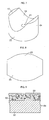
Fig. 3 is an explanatory enlarged cross-sectional view of the rack guide in the embodiment shown inFig. 1 ; -
Fig. 4 is an explanatory partially enlarged cross-sectional view of the rack guide in the embodiment shown inFig. 3 ; -
Fig. 5 is an explanatory cross-sectional view taken in the direction of arrows along line V - V shown inFig. 2 ; -
Fig. 6 is an explanatory bottom view of the rack guide shown inFig. 2 ; -
Fig. 7 is an explanatory perspective view of a rack guide base body in the rack guide shown inFig. 2 ; -
Fig. 8 is an explanatory plan view of a sliding plate piece material in the rack guide shown inFig. 2 ; -
Fig. 9 is an explanatory cross-sectional view of a multilayered plate for forming a curved sliding plate piece; -
Fig. 10 is an explanatory plan view of another embodiment of the rack guide in accordance with the invention; -
Fig. 11 is an explanatory perspective view of the rack guide base body in the rack guide shown inFig. 10 ; and -
Fig. 12 is an explanatory enlarged cross-sectional view of still another embodiment of the rack guide. - Hereafter, a more detailed description will be given of the mode for carrying out the invention with reference to the preferred embodiments illustrated in the drawings. It should be noted that the invention is not limited by these embodiments.
- In
Figs. 1 to 8 , a rack-and-pinion type steering apparatus 1 in accordance with this embodiment is comprised of agear case 3 having ahollow portion 2; a steering shaft 6 supported in thehollow portion 2 of thegear case 3 by means ofrolling bearings pinion 7 which is supported by being integrally provided on a shaft end of the steering shaft 6, and is disposed in thehollow portion 2 of thegear case 3 through the steering shaft 6 rotatably in the R direction; arack bar 10 which hasrack teeth 8 meshing with thepinion 7 and has an arcuate outerperipheral surface 9 of a predetermined radius of curvature on its back surface relative to therack teeth 8; arack guide 11 which is disposed movably in thehollow portion 2 of thegear case 3 and guides and supports therack bar 10 movably in an axial direction A; and acoil spring 12 serving as a resilient means which is disposed in thehollow portion 2 of thegear case 3 and resiliently presses therack teeth 8 of therack bar 10 toward thepinion 7 by means of therack guide 11. - The
gear case 3 has amain body portion 13 for supporting therolling bearings cylindrical portion 14 formed integrally on themain body portion 13, and acover member 16 secured to the hollowcylindrical portion 14 so as to close anopening 15 of the hollowcylindrical portion 14. - The
rack bar 10, which is passed through thegear case 3 in the axial direction A, i.e., a perpendicular direction to the axis of the steering shaft 6, and is disposed movably in that axial direction A, has the arcuate outerperipheral surface 9 on its rear surface side (back surface) opposing its surface where therack teeth 8 are formed. - The
rack guide 11 includes a synthetic resin-made rackguide base body 22 which has an arcuateconcave surface 18 provided at its oneend face 17 in such a manner as to oppose the arcuate outerperipheral surface 9 of therack bar 10 and having a substantially elliptical shape in a plan view, a hollow recessedportion 20 provided at itsother end face 19, and a circular throughhole 21 which at its one end is open in a central portion of the arcuateconcave surface 18 and which at its other end is open in the hollow recessedportion 20; and a curved slidingplate piece 26 which is disposed on the arcuateconcave surface 18 having the substantially elliptical shape in a plan view and which has an arcuateconcave surface 23 for supporting the arcuate outerperipheral surface 9 of therack bar 10 slidably, an arcuateconvex surface 24 which is brought into close contact with the arcuateconcave surface 18 of the rackguide base body 22, and atubular projecting portion 25 provided integrally on thearcuate convex surface 24. - The hollow recessed
portion 20, which is open at theend face 19, is defined by a cylindrical innerperipheral surface 28 of the rackguide base body 22 and anannular ceiling surface 29 of the rackguide base body 22. A plurality of reinforcingvertical ribs 30 are integrally formed on the cylindrical innerperipheral surface 28 in such a manner as to be spaced apart at equal intervals in a circumferential direction, while a plurality of reinforcinghorizontal ribs 31 are integrally formed on theceiling surface 29 in such a manner as to be connected to the respectivevertical ribs 30 and to be spaced apart at equal intervals in the circumferential direction. The circular throughhole 21 is open at theceiling surface 29 to the hollow recessedportion 20. - The rack
guide base body 22 is preferably formed of a thermoplastic synthetic resin containing as a reinforcingfiller 30 to 50% by mass of at least one inorganic substance selected from glass fiber, carbon fiber, and glass powder, and the thermoplastic synthetic resin is preferably selected from polyacetal resin, polyamide resin, polyester resin including polybutylene terephthalate (PBT) and polyethylene terephthalate (PET), and polyphenylene sulfide resin. - The rack
guide base body 22 is, at its cylindricalouter surface 34, in contact with aninner surface 35 of the hollowcylindrical portion 14 of thegear case 3 slidably in a B direction which is a perpendicular direction to the axial direction A and is a perpendicular direction to the axis of the steering shaft 6, whereby therack guide 11 is slidable in the B direction. - The projecting
portion 25 has atubular portion 41 provided integrally on the arcuateconvex surface 24 at one end thereof, aclosed bottom portion 42 provided at the other end of thetubular portion 41, and a bulgedportion 43 which is provided integrally on each of thetubular portion 41 and theclosed bottom portion 42 and is expanded radially outwardly from thetubular portion 41 and theclosed bottom portion 42, the bulgedportion 43 being integrally connected at its one end to thetubular portion 41 and at its other end to theclosed bottom portion 42. - The curved sliding
plate piece 26, which has a substantially elliptical shape in a plan view and is bent in a curved shape as a whole, is secured to the rackguide base body 22 by press-fitting itstubular portion 41 into the circular throughhole 21 and by causing the bulgedportion 43 to be brought into pressure contact with theceiling surface 29 of the rackguide base body 22 around the other end of the circular throughhole 21. The bulgedportion 43 is formed by caulking a circular outer rim of theclosed bottom portion 42 in the securing of the curved slidingplate piece 26 to the rackguide base body 22. - The curved sliding
plate piece 26 is formed such that, as shown inFig. 7 , a slidingplate piece material 55 of a substantially elliptical shape is formed by stamping a three-layeredmultilayered plate 54 comprised of athin steel plate 51 serving as a back plate, a poroussintered metal layer 52 integrally coated and formed on the surface of thethin steel plate 51, and asynthetic resin layer 53 coated on the surface of the poroussintered metal layer 52 in such a manner as to fill pores of the poroussintered metal layer 52, as shown inFig. 8 , and the slidingplate piece material 55 is then subjected to press bending so as to obtain the arcuateconcave surface 23 constituted by an exposed surface of thesynthetic resin layer 53, and is further subjected to drawing so as to obtain the projectingportion 25 having theclosed bottom portion 42 at its distal end integrally. - The arcuate
concave surface 23 of the curved slidingplate piece 26 has an arcuateconcave surface 61 and a pair of arcuateconcave surfaces 62, and is, at the arcuateconcave surface 61, brought into slidable contact with the arcuate outerperipheral surface 9 of therack bar 10 to support therack bar 10 movably in the axial direction A, such that each of the arcuateconcave surfaces 62 does not come into contact with the arcuate outerperipheral surface 9 and opposes the arcuate outerperipheral surface 9 of therack bar 10 with a clearance therebetween. The arcuateconvex surface 24 of the curved slidingplate piece 26, which is the reverse side (back surface) to the arcuateconcave surface 23 having the arcuateconcave surface 61 and the pair of arcuateconcave surfaces 62, also has an arcuateconvex surface 63 and a pair of arcuateconvex surfaces 64 which are similar to the arcuateconcave surface 61 and the pair of arcuate concave surfaces 62. - The arcuate
concave surface 61 has a center of curvature O1 substantially identical to a center of curvature O1 of the arcuate outerperipheral surface 9 of therack bar 10 and has a radius of curvature identical to the radius of curvature of the arcuate outerperipheral surface 9 of therack bar 10, so as to come into contact with the arcuate outerperipheral surface 9 of therack bar 10 in anangular range 66 from an angle 0° to an angle not exceeding 50° on each of one side and the other side in an angular direction of acenter line 65 passing through the center of curvature O1 of the arcuate outerperipheral surface 9 of therack bar 10. Meanwhile, the arcuateconcave surfaces 62 respectively have centers ofcurvature peripheral surface 9 of therack bar 10 and have a radius of curvature greater than the radius of curvature of the arcuate outerperipheral surface 9 of therack bar 10, so as to have a clearance with the arcuate outerperipheral surface 9 of therack bar 10, without coming into contact therewith, in anangular range 67 exceeding an angle 50° on each of one side and the other side in the angular direction of thecenter line 65 passing through the center of curvature O1 of the arcuate outerperipheral surface 9 of therack bar 10. The arcuateconcave surface 61 and the pair of arcuateconcave surfaces 62 are thus formed symmetrically with respect to thecenter line 65. - Preferably, the arcuate
convex surface 63 and the pair of arcuateconvex surfaces 64 respectively have similar shapes with greater radii of curvature than the respective radii of curvature of the corresponding arcuateconcave surface 61 and pair of arcuateconcave surfaces 62, and are thus formed symmetrically with respect to thecenter line 65. - The arcuate
concave surface 18 of the rackguide base body 22 is formed by an arcuateconcave surface 71 and a pair of arcuateconcave surfaces 72 having complementary shapes to the shapes of the arcuateconvex surface 63 and the pair of arcuateconvex surfaces 64 of the curved slidingplate piece 26 so as to be brought into close contact with the arcuateconvex surface 63 and the pair of arcuate convex surfaces 64. - The
coil spring 12, which is disposed in such a manner as to be surrounded byside surfaces 74 of thevertical ribs 30 in the hollow recessedportion 20 of the rackguide base body 22, abuts at its one end againstlower surfaces 75 of thehorizontal ribs 31 and at its other end against thecover member 16 closing theopening 15 of the hollowcylindrical portion 14 of thegear case 3, and presses the curved slidingplate piece 26 toward therack bar 10 by means of the rackguide base body 22. - In the above-described rack-and-pinion type steering apparatus 1, the
rack guide 11 ensures the meshing of therack teeth 8 with thepinion 7 by the pressing of the curved slidingplate piece 26 against therack bar 10 through the resiliency of thecoil spring 12, and guides the sliding movement of therack bar 10 in the axial direction A caused by that meshing in the rotation of the steering shaft 6 in the R direction by the sliding contact of the arcuate outerperipheral surface 9 of therack bar 10 with the arcuateconcave surface 61 of the curved sliding plate piece 33. - In the rack-and-pinion type steering apparatus 1, since the curved sliding
plate piece 26 is secured to the rackguide base body 22 by being brought into pressure contact at its bulgedportion 43 with theceiling surface 29 of the rackguide base body 22 around the other end of the circular throughhole 21, it is possible to maintain the securing of the curved slidingplate piece 26 to the rackguide base body 22 over extended periods of time even in cases stress relaxation has occurred in the rackguide base body 22 by being affected by the temperature rise of the rack-and-pinion type steering apparatus 1, and the press-fitting force at thetubular portion 41 into the rackguide base body 22 has declined. As a result, the curved slidingplate piece 26 can be similarly held securely on the rackguide base body 22 over extended periods of time, and therack bar 10 is able to maintain its surface contact with the curved slidingplate piece 26 over the angular ranges 66 over extended periods of time as in the state of its initial setting. In addition, as a result of the fact that therack bar 10 remains in surface contact with the curved slidingplate piece 26 in the angular ranges 66, the fracture strength of the rackguide base body 22 is improved, and the wear resistance of the curved slidingplate piece 26 is improved. - Although, in the above description, the curved sliding
plate piece 26 is used which is substantially elliptical in a plan view and is bent in a curved shape as a whole, therack guide 11 may alternatively be formed, as shown inFigs. 9 and10 , such that, as the curved slidingplate piece 26, a rectangular slidingplate piece material 55 is formed by stamping or cutting the three-layeredmultilayered plate 54 into a rectangular shape, and is subjected to bending and drawing in the same way as described above to thereby form a curved slidingplate piece 81 which is rectangular in a plan view; meanwhile, a pair of plan-view substantially semiellipticalconcave surfaces 82 and a plan-view rectangularconcave portion 83, which is sandwiched by the pair of plan-view substantially semiellipticalconcave surfaces 82 and on which the arcuateconcave surface 18 having a substantially elliptical shape in a plan view is formed, are formed on the oneend face 17 of the rackguide base body 22, and the curved slidingplate piece 81 serving as the curved slidingplate piece 26 is fitted and secured to the plan-view rectangularconcave portion 83. Also with the rack-and-pinion type steering apparatus 1 using therack guide 11 having the rackguide base body 22, on the oneend face 17 of which are provided the pair of plan-view substantially semiellipticalconcave surfaces 82 and the plan-view rectangularconcave portion 83 sandwiched by the pair of plan-view substantially semiellipticalconcave surfaces 82 and having the arcuateconcave surface 18 formed thereon, as well as the curved slidingplate piece 81 fitted and secured to the plan-view rectangularconcave portion 83 of the rackguide base body 22, the curved slidingplate piece 81 is secured to the rackguide base body 22 such that thetubular portion 41 of the curved slidingplate piece 81 is press-fitted in the circular throughhole 21, and the bulgedportion 43 of the curved slidingplate piece 81 is brought into pressure contact with theceiling surface 29 of the rackguide base body 22 around the other end of the circular throughhole 21; therefore, it is possible to obtain similar advantages to those described above. Furthermore, since the curved slidingplate piece 81 is fitted and secured to the plan-view rectangularconcave portion 83, such advantages can be obtained more satisfactorily. - Furthermore, in the above description, on the arcuate
concave surface 23 and the arcuateconvex surface 24 of the curved slidingplate piece 26, the arcuateconcave surface 61 and the pair of arcuateconcave surfaces 62 are formed symmetrically with respect to thecenter line 65 so as to come into contact as a whole with the arcuate outerperipheral surface 9 of therack bar 10 in the angular ranges 66 from an angle 0° to an angle not exceeding 50° and to have a clearance with the arcuate outerperipheral surface 9 of therack bar 10, without coming into contact therewith, in theangular range 67 exceeding the angle 50°, and the arcuateconvex surface 63 and the pair of arcuateconvex surfaces 64 are formed symmetrically about thecenter line 65 with similar shapes with greater radii of curvature than the respective radii of curvature of the corresponding arcuateconcave surface 61 and pair of arcuateconcave surfaces 62, while the arcuateconcave surface 18 of the rackguide base body 22 is formed by the arcuateconcave surface 71 and the pair of arcuateconcave surfaces 72 having complementary shapes to the shapes of the arcuateconvex surface 63 and the pair of arcuateconvex surfaces 64 so as to be brought into close contact with the arcuateconvex surface 63 and the pair of arcuate convex surfaces 64. Alternatively, however, as shown inFig. 12 , the arcuateconcave surface 23 of the curved slidingplate piece 26 may be formed by being provided with two arcuateconcave surfaces rack bar 10 movably in the axial direction A by partially coming into slidable contact with the arcuate outerperipheral surface 9 of therack bar 10 at the arcuateconcave surfaces convex surface 24 of the curved slidingplate piece 26, which is the reverse side (back surface) to the arcuateconcave surface 23 having the two arcuateconcave surfaces convex surfaces - In the curved sliding
plate piece 26 shown inFig. 12 , the arcuateconcave surface 85 has a radius ofcurvature 02 off-centered from the center of curvature O1 of the arcuate outerperipheral surface 9 of therack bar 10 and have a radius of curvature greater than the radius of curvature of the arcuate outerperipheral surface 9 of therack bar 10, so as to circumscribe the arcuate outerperipheral surface 9 of therack bar 10 at a region of anangular range 89 of from 0° to 90°, i.e., at aregion 90 of an angle 45° in this embodiment, on one side in the angular direction of thecenter line 65 passing through the center of curvature O1 of the arcuate outerperipheral surface 9 of therack bar 10. On the other hand, the arcuateconcave surface 86 has a center ofcurvature 03 off-centered from the center of curvature O1 of the arcuate outerperipheral surface 9 of therack bar 10 and have a radius of curvature which is greater than the radius of curvature of therack bar 10 and is identical to the radius of curvature of the arcuateconcave surface 85, so as to circumscribe the arcuate outerperipheral surface 9 of therack bar 10 at a region of anangular range 91 of from 0° to 90°, i.e., at aregion 92 of an angle α = 45° in this embodiment, on the other side in the angular direction of thecenter line 65 passing through the center of curvature O1 of the arcuate outerperipheral surface 9 of therack bar 10. The two arcuateconcave surfaces center line 65, and preferably the two arcuateconvex surfaces concave surfaces Fig. 12 , the arcuateconcave surface 18 of the rackguide base body 22 is sufficient if it is formed by two arcuateconcave surfaces convex surfaces plate piece 26 so as to be brought into close contact with the arcuateconvex surfaces - According to the embodiment shown in
Fig. 12 , coupled with the above-described advantage that the curved slidingplate piece 26 can be similarly held securely on the rackguide base body 22 over extended periods of time, and the line contact or narrow belt-like contact of therack bar 10 with the curved slidingplate piece 26 at theregions rack bar 10 and the curved slidingplate piece 26 can be substantially reduced as the result of the line contact of therack bar 10 with the curved slidingplate piece 26 at theregions regions regions -
- 9:
- arcuate outer peripheral surface
- 10:
- rack bar
- 11:
- rack guide
- 17:
- end face
- 18:
- arcuate concave surface
- 19:
- end face
- 20:
- hollow recessed portion
- 21:
- circular through hole
- 22:
- rack guide base body
- 23:
- arcuate concave surface
- 24:
- arcuate convex surface
- 25:
- projecting portion
- 26:
- curved sliding plate piece
Claims (13)
- A rack guide comprising:a synthetic resin-made rack guide base body which has an arcuate concave surface provided at one end face thereof, a hollow recessed portion provided at another end face thereof, and a circular through hole which at one end thereof is open in a central portion of the arcuate concave surface and which at another end thereof is open in the hollow recessed portion; and a curved sliding plate piece which has an arcuate concave surface for supporting an arcuate outer peripheral surface of a rack bar slidably, an arcuate convex surface which is brought into close contact with the arcuate concave surface of said rack guide base body, and a tubular projecting portion which is provided integrally on the arcuate convex surface, and which is open in the arcuate concave surface and has an interior closed with respect to the hollow recessed portion,wherein the projecting portion has a tubular portion provided integrally on the arcuate convex surface at one end thereof, a closed bottom portion provided at the other end of the tubular portion, and a bulged portion which is on one side thereof provided integrally on the tubular portion and is on another side thereof provided integrally on the closed bottom portion and is expanded radially outwardly, andsaid curved sliding plate piece is secured to said rack guide base body as the tubular portion is press-fitted into the circular through hole and the bulged portion is brought into pressure contact with said rack guide base body around the other end of the circular through hole.
- The rack guide according to claim 1, wherein the bulged portion is formed by caulking a circular outer rim of the closed bottom portion in the securing of said curved sliding plate piece to said rack guide base body.
- The rack guide according to claim 1 or 2, wherein said curved sliding plate piece includes a back plate, a porous sintered metal layer integrally coated and formed on a surface of the back plate, and a synthetic resin layer coated on a surface of the porous sintered metal layer in such a manner as to fill pores of the porous sintered metal layer, and the arcuate concave surface is constituted by an exposed surface of the synthetic resin layer.
- The rack guide according to any one of claims 1 to 3, wherein the arcuate concave surface has a substantially elliptical shape in a plan view.
- The rack guide according to claim 4, wherein said curved sliding plate piece has a substantially elliptical shape in a plan view and is disposed on the arcuate concave surface having the substantially elliptical shape in a plan view.
- The rack guide according to any one of claims 1 to 3, wherein said rack guide base body has on the one end face thereof a pair of plan-view substantially semielliptical concave surfaces and a plan-view rectangular concave portion which is sandwiched by the pair of plan-view substantially semielliptical concave surfaces and on which the arcuate concave surface is formed.
- The rack guide according to claim 6, wherein said curved sliding plate piece has a rectangular shape in a plan view and is fitted and secured to the plan-view rectangular concave portion.
- The rack guide according to any one of claims 1 to 7, wherein the arcuate concave surface of said curved sliding plate piece is constituted by two arcuate concave surfaces which are symmetrical with respect to a center line passing through a center of curvature of the arcuate outer peripheral surface of the rack bar, such that, in an angular range from an angle 0° to an angle not exceeding 50° on either side in an angular direction of the center line passing through the center of curvature of the arcuate outer peripheral surface of the rack bar, each of the arcuate concave surfaces has as its center of curvature the center of curvature of the arcuate outer peripheral surface of the rack bar and has a radius of curvature substantially identical to a radius of curvature of the arcuate outer peripheral surface of the rack bar, so as to come into contact with the arcuate outer peripheral surface of the rack bar, whereas, in an angular range exceeding an angle 50°, each of the arcuate concave surfaces has a center of curvature off-centered from the center of curvature of the arcuate outer peripheral surface of the rack bar and has a radius of curvature greater than the radius of curvature of the arcuate outer peripheral surface of the rack bar, so as to have a clearance with the arcuate outer peripheral surface of the rack bar.
- The rack guide according to any one of claims 1 to 7, wherein the arcuate concave surface of said curved sliding plate piece is constituted by two arcuate concave surfaces which are symmetrical with respect to a center line passing through a center of curvature of the arcuate outer peripheral surface of the rack bar, such that each of the arcuate concave surfaces has a center of curvature off-centered from a center of curvature of the arcuate outer peripheral surface of the rack bar and has a radius of curvature greater than a radius of curvature of the arcuate outer peripheral surface of the rack bar, so as to so as to respectively come into contact with the arcuate outer peripheral surface of the rack bar at each of two regions in an angular range from 0° to 90° on each side of the center line passing through the center of curvature of the arcuate outer peripheral surface of the rack bar.
- The rack guide according to claim 9, wherein the angular range is from 30° to 60° or from 30° to 45°.
- The rack guide according to any one of claims 1 to 10, wherein said rack guide base body is formed of a thermoplastic synthetic resin containing as a reinforcing filler 30 to 50% by mass of at least one inorganic substance selected from glass fiber, carbon fiber, and glass powder.
- The rack guide according to claim 11, wherein the thermoplastic synthetic resin is selected from polyacetal resin, polyamide resin, polyester resin, and polyphenylene sulfide resin.
- A rack-and-pinion type steering apparatus comprising:a gear case having a hollow portion;a pinion which is disposed rotatably in the hollow portion of said gear case and is rotated by steering;a rack bar having rack teeth meshing with said pinion;a rack guide according to any one of claims 1 to 12 which is disposed movably in the hollow portion of said gear case and guides and supports said rack bar movably; andresilient means which is disposed in the hollow portion of said gear case and resiliently presses the rack teeth of said rack bar against said pinion by means of said rack guide.
Applications Claiming Priority (2)
| Application Number | Priority Date | Filing Date | Title |
|---|---|---|---|
| JP2011165933A JP6106914B2 (en) | 2011-07-28 | 2011-07-28 | Rack guide and rack and pinion type steering apparatus provided with the rack guide |
| PCT/JP2012/004459 WO2013014870A1 (en) | 2011-07-28 | 2012-07-10 | Rack guide, and rack and pinion steering device with rack guide |
Publications (3)
| Publication Number | Publication Date |
|---|---|
| EP2738065A1 true EP2738065A1 (en) | 2014-06-04 |
| EP2738065A4 EP2738065A4 (en) | 2015-08-26 |
| EP2738065B1 EP2738065B1 (en) | 2017-11-01 |
Family
ID=47600748
Family Applications (1)
| Application Number | Title | Priority Date | Filing Date |
|---|---|---|---|
| EP12817126.1A Active EP2738065B1 (en) | 2011-07-28 | 2012-07-10 | Rack guide, and rack and pinion steering device with rack guide |
Country Status (5)
| Country | Link |
|---|---|
| EP (1) | EP2738065B1 (en) |
| JP (1) | JP6106914B2 (en) |
| CN (1) | CN103702892A (en) |
| BR (1) | BR112014000981A2 (en) |
| WO (1) | WO2013014870A1 (en) |
Cited By (1)
| Publication number | Priority date | Publication date | Assignee | Title |
|---|---|---|---|---|
| KR20170047919A (en) * | 2015-10-26 | 2017-05-08 | 현대자동차주식회사 | Device for supporting rack for steering of vehicle |
Families Citing this family (3)
| Publication number | Priority date | Publication date | Assignee | Title |
|---|---|---|---|---|
| JP6661867B2 (en) * | 2014-09-24 | 2020-03-11 | 大豊工業株式会社 | Rack guide and rack and pinion type steering device provided with the rack guide |
| JP6710174B2 (en) * | 2017-03-16 | 2020-06-17 | オイレス工業株式会社 | Rack guide and gear mechanism |
| JP7108507B2 (en) * | 2018-09-19 | 2022-07-28 | オイレス工業株式会社 | Multi-layer sliding member and automobile rack and pinion steering device using the same |
Family Cites Families (17)
| Publication number | Priority date | Publication date | Assignee | Title |
|---|---|---|---|---|
| JPS5021973A (en) * | 1973-06-28 | 1975-03-08 | ||
| DE2402062A1 (en) * | 1974-01-17 | 1975-07-24 | Zahnradfabrik Friedrichshafen | RACK STEERING GEAR, IN PARTICULAR FOR KRFAT VEHICLES |
| JPS57174272U (en) * | 1981-04-30 | 1982-11-02 | ||
| JPS58188263U (en) * | 1982-06-04 | 1983-12-14 | 光洋精工株式会社 | Rack and pinion type steering device rack shaft support device |
| JPS60105568U (en) * | 1983-12-26 | 1985-07-18 | オイレス工業株式会社 | Rack and pinion steering device |
| JPS61123430A (en) * | 1984-11-19 | 1986-06-11 | Sobi Kogei:Kk | Joining method between plate-shaped members |
| JPS646382U (en) | 1987-06-30 | 1989-01-13 | ||
| JPS6427495U (en) | 1987-08-10 | 1989-02-16 | ||
| JPH0738721U (en) * | 1993-12-17 | 1995-07-14 | 市光工業株式会社 | Mounting structure for automobile parts |
| JP3264099B2 (en) * | 1994-05-31 | 2002-03-11 | オイレス工業株式会社 | Rack and pinion steering system |
| JP3264100B2 (en) * | 1994-05-31 | 2002-03-11 | オイレス工業株式会社 | Rack and pinion steering system |
| JP3276064B2 (en) * | 1997-09-26 | 2002-04-22 | 大同メタル工業株式会社 | Rack guide for rack and pinion type steering device |
| JP2000177604A (en) * | 1998-12-11 | 2000-06-27 | Oiles Ind Co Ltd | Rack and pinion type steering device |
| JP5103699B2 (en) * | 2001-05-15 | 2012-12-19 | 株式会社ジェイテクト | Rack and pinion steering system |
| EP1508708A1 (en) * | 2003-08-22 | 2005-02-23 | Delphi Technologies, Inc. | Multi layer bearing liner for a rack guide |
| JP4539128B2 (en) * | 2004-03-09 | 2010-09-08 | オイレス工業株式会社 | Rack guide for rack and pinion type steering system |
| US20050257635A1 (en) * | 2004-05-24 | 2005-11-24 | Damore Michael J | Rack yoke assembly |
-
2011
- 2011-07-28 JP JP2011165933A patent/JP6106914B2/en active Active
-
2012
- 2012-07-10 WO PCT/JP2012/004459 patent/WO2013014870A1/en active Application Filing
- 2012-07-10 EP EP12817126.1A patent/EP2738065B1/en active Active
- 2012-07-10 BR BR112014000981A patent/BR112014000981A2/en not_active Application Discontinuation
- 2012-07-10 CN CN201280036135.2A patent/CN103702892A/en active Pending
Cited By (1)
| Publication number | Priority date | Publication date | Assignee | Title |
|---|---|---|---|---|
| KR20170047919A (en) * | 2015-10-26 | 2017-05-08 | 현대자동차주식회사 | Device for supporting rack for steering of vehicle |
Also Published As
| Publication number | Publication date |
|---|---|
| WO2013014870A1 (en) | 2013-01-31 |
| BR112014000981A2 (en) | 2017-02-21 |
| JP2013028285A (en) | 2013-02-07 |
| EP2738065B1 (en) | 2017-11-01 |
| EP2738065A4 (en) | 2015-08-26 |
| CN103702892A (en) | 2014-04-02 |
| JP6106914B2 (en) | 2017-04-05 |
Similar Documents
| Publication | Publication Date | Title |
|---|---|---|
| EP1975430A1 (en) | Bush bearing device, and rack and pinion steering device for automobile, using the same | |
| EP2296957B1 (en) | Steering yoke | |
| EP2738065B1 (en) | Rack guide, and rack and pinion steering device with rack guide | |
| EP1882622A1 (en) | Rack guide, and rack and pinion steering device with the rack guide | |
| JPH0712621U (en) | Ball joint | |
| JP6909789B2 (en) | Plain bearing | |
| EP2891809A1 (en) | Bush bearing, and rack-and-pinion steering device adapted for use in automobile and using same | |
| EP3132994A1 (en) | Rack guide and rack-and-pinion steering device provided with same rack guide | |
| JPWO2019069795A1 (en) | Plain bearing | |
| KR102441668B1 (en) | Rack guide and gear mechanism | |
| JP3264099B2 (en) | Rack and pinion steering system | |
| JP2011027237A (en) | Method for arranging receiving part and retaining part in ball joint bearing seat | |
| JP4003430B2 (en) | Method of manufacturing rack guide for rack and pinion type steering device | |
| JP3264100B2 (en) | Rack and pinion steering system | |
| JPH08133099A (en) | Pack guide for pack pinion type steering system and manufacture thereof | |
| JP6307861B2 (en) | Resin cage | |
| JP2000168577A (en) | Manufacture of rack guide of rack-and-pinion type steering device, and pack-and-pinion type steering device equipped with the rack guide | |
| JP5673757B2 (en) | Rack and pinion steering system | |
| JP2018040490A (en) | Thrust slide bearing | |
| JP5041220B2 (en) | Ball joint | |
| JP5590566B2 (en) | Rack and pinion steering system | |
| JP2007203836A (en) | Rack guide and rack and pinion type steering system using the same | |
| JP5358943B2 (en) | Split roller bearing | |
| JPH07323849A (en) | Steering device of rack-pinion type | |
| JP2008095737A (en) | Universal joint |
Legal Events
| Date | Code | Title | Description |
|---|---|---|---|
| PUAI | Public reference made under article 153(3) epc to a published international application that has entered the european phase |
Free format text: ORIGINAL CODE: 0009012 |
|
| 17P | Request for examination filed |
Effective date: 20140108 |
|
| AK | Designated contracting states |
Kind code of ref document: A1 Designated state(s): AL AT BE BG CH CY CZ DE DK EE ES FI FR GB GR HR HU IE IS IT LI LT LU LV MC MK MT NL NO PL PT RO RS SE SI SK SM TR |
|
| DAX | Request for extension of the european patent (deleted) | ||
| RA4 | Supplementary search report drawn up and despatched (corrected) |
Effective date: 20150723 |
|
| RIC1 | Information provided on ipc code assigned before grant |
Ipc: B62D 3/12 20060101AFI20150717BHEP |
|
| GRAP | Despatch of communication of intention to grant a patent |
Free format text: ORIGINAL CODE: EPIDOSNIGR1 |
|
| STAA | Information on the status of an ep patent application or granted ep patent |
Free format text: STATUS: GRANT OF PATENT IS INTENDED |
|
| INTG | Intention to grant announced |
Effective date: 20170705 |
|
| GRAS | Grant fee paid |
Free format text: ORIGINAL CODE: EPIDOSNIGR3 |
|
| GRAA | (expected) grant |
Free format text: ORIGINAL CODE: 0009210 |
|
| STAA | Information on the status of an ep patent application or granted ep patent |
Free format text: STATUS: THE PATENT HAS BEEN GRANTED |
|
| RAP1 | Party data changed (applicant data changed or rights of an application transferred) |
Owner name: OILES CORPORATION |
|
| AK | Designated contracting states |
Kind code of ref document: B1 Designated state(s): AL AT BE BG CH CY CZ DE DK EE ES FI FR GB GR HR HU IE IS IT LI LT LU LV MC MK MT NL NO PL PT RO RS SE SI SK SM TR |
|
| REG | Reference to a national code |
Ref country code: GB Ref legal event code: FG4D |
|
| REG | Reference to a national code |
Ref country code: AT Ref legal event code: REF Ref document number: 941736 Country of ref document: AT Kind code of ref document: T Effective date: 20171115 Ref country code: CH Ref legal event code: EP |
|
| REG | Reference to a national code |
Ref country code: IE Ref legal event code: FG4D |
|
| REG | Reference to a national code |
Ref country code: DE Ref legal event code: R096 Ref document number: 602012039311 Country of ref document: DE |
|
| REG | Reference to a national code |
Ref country code: NL Ref legal event code: MP Effective date: 20171101 |
|
| REG | Reference to a national code |
Ref country code: LT Ref legal event code: MG4D |
|
| REG | Reference to a national code |
Ref country code: AT Ref legal event code: MK05 Ref document number: 941736 Country of ref document: AT Kind code of ref document: T Effective date: 20171101 |
|
| PG25 | Lapsed in a contracting state [announced via postgrant information from national office to epo] |
Ref country code: NO Free format text: LAPSE BECAUSE OF FAILURE TO SUBMIT A TRANSLATION OF THE DESCRIPTION OR TO PAY THE FEE WITHIN THE PRESCRIBED TIME-LIMIT Effective date: 20180201 Ref country code: LT Free format text: LAPSE BECAUSE OF FAILURE TO SUBMIT A TRANSLATION OF THE DESCRIPTION OR TO PAY THE FEE WITHIN THE PRESCRIBED TIME-LIMIT Effective date: 20171101 Ref country code: ES Free format text: LAPSE BECAUSE OF FAILURE TO SUBMIT A TRANSLATION OF THE DESCRIPTION OR TO PAY THE FEE WITHIN THE PRESCRIBED TIME-LIMIT Effective date: 20171101 Ref country code: SE Free format text: LAPSE BECAUSE OF FAILURE TO SUBMIT A TRANSLATION OF THE DESCRIPTION OR TO PAY THE FEE WITHIN THE PRESCRIBED TIME-LIMIT Effective date: 20171101 Ref country code: NL Free format text: LAPSE BECAUSE OF FAILURE TO SUBMIT A TRANSLATION OF THE DESCRIPTION OR TO PAY THE FEE WITHIN THE PRESCRIBED TIME-LIMIT Effective date: 20171101 Ref country code: FI Free format text: LAPSE BECAUSE OF FAILURE TO SUBMIT A TRANSLATION OF THE DESCRIPTION OR TO PAY THE FEE WITHIN THE PRESCRIBED TIME-LIMIT Effective date: 20171101 |
|
| PG25 | Lapsed in a contracting state [announced via postgrant information from national office to epo] |
Ref country code: LV Free format text: LAPSE BECAUSE OF FAILURE TO SUBMIT A TRANSLATION OF THE DESCRIPTION OR TO PAY THE FEE WITHIN THE PRESCRIBED TIME-LIMIT Effective date: 20171101 Ref country code: GR Free format text: LAPSE BECAUSE OF FAILURE TO SUBMIT A TRANSLATION OF THE DESCRIPTION OR TO PAY THE FEE WITHIN THE PRESCRIBED TIME-LIMIT Effective date: 20180202 Ref country code: IS Free format text: LAPSE BECAUSE OF FAILURE TO SUBMIT A TRANSLATION OF THE DESCRIPTION OR TO PAY THE FEE WITHIN THE PRESCRIBED TIME-LIMIT Effective date: 20180301 Ref country code: BG Free format text: LAPSE BECAUSE OF FAILURE TO SUBMIT A TRANSLATION OF THE DESCRIPTION OR TO PAY THE FEE WITHIN THE PRESCRIBED TIME-LIMIT Effective date: 20180201 Ref country code: AT Free format text: LAPSE BECAUSE OF FAILURE TO SUBMIT A TRANSLATION OF THE DESCRIPTION OR TO PAY THE FEE WITHIN THE PRESCRIBED TIME-LIMIT Effective date: 20171101 Ref country code: HR Free format text: LAPSE BECAUSE OF FAILURE TO SUBMIT A TRANSLATION OF THE DESCRIPTION OR TO PAY THE FEE WITHIN THE PRESCRIBED TIME-LIMIT Effective date: 20171101 Ref country code: RS Free format text: LAPSE BECAUSE OF FAILURE TO SUBMIT A TRANSLATION OF THE DESCRIPTION OR TO PAY THE FEE WITHIN THE PRESCRIBED TIME-LIMIT Effective date: 20171101 |
|
| REG | Reference to a national code |
Ref country code: FR Ref legal event code: PLFP Year of fee payment: 7 |
|
| PG25 | Lapsed in a contracting state [announced via postgrant information from national office to epo] |
Ref country code: SK Free format text: LAPSE BECAUSE OF FAILURE TO SUBMIT A TRANSLATION OF THE DESCRIPTION OR TO PAY THE FEE WITHIN THE PRESCRIBED TIME-LIMIT Effective date: 20171101 Ref country code: CZ Free format text: LAPSE BECAUSE OF FAILURE TO SUBMIT A TRANSLATION OF THE DESCRIPTION OR TO PAY THE FEE WITHIN THE PRESCRIBED TIME-LIMIT Effective date: 20171101 Ref country code: CY Free format text: LAPSE BECAUSE OF FAILURE TO SUBMIT A TRANSLATION OF THE DESCRIPTION OR TO PAY THE FEE WITHIN THE PRESCRIBED TIME-LIMIT Effective date: 20171101 Ref country code: DK Free format text: LAPSE BECAUSE OF FAILURE TO SUBMIT A TRANSLATION OF THE DESCRIPTION OR TO PAY THE FEE WITHIN THE PRESCRIBED TIME-LIMIT Effective date: 20171101 Ref country code: EE Free format text: LAPSE BECAUSE OF FAILURE TO SUBMIT A TRANSLATION OF THE DESCRIPTION OR TO PAY THE FEE WITHIN THE PRESCRIBED TIME-LIMIT Effective date: 20171101 |
|
| REG | Reference to a national code |
Ref country code: DE Ref legal event code: R097 Ref document number: 602012039311 Country of ref document: DE |
|
| PG25 | Lapsed in a contracting state [announced via postgrant information from national office to epo] |
Ref country code: SM Free format text: LAPSE BECAUSE OF FAILURE TO SUBMIT A TRANSLATION OF THE DESCRIPTION OR TO PAY THE FEE WITHIN THE PRESCRIBED TIME-LIMIT Effective date: 20171101 Ref country code: IT Free format text: LAPSE BECAUSE OF FAILURE TO SUBMIT A TRANSLATION OF THE DESCRIPTION OR TO PAY THE FEE WITHIN THE PRESCRIBED TIME-LIMIT Effective date: 20171101 Ref country code: RO Free format text: LAPSE BECAUSE OF FAILURE TO SUBMIT A TRANSLATION OF THE DESCRIPTION OR TO PAY THE FEE WITHIN THE PRESCRIBED TIME-LIMIT Effective date: 20171101 Ref country code: PL Free format text: LAPSE BECAUSE OF FAILURE TO SUBMIT A TRANSLATION OF THE DESCRIPTION OR TO PAY THE FEE WITHIN THE PRESCRIBED TIME-LIMIT Effective date: 20171101 |
|
| PLBE | No opposition filed within time limit |
Free format text: ORIGINAL CODE: 0009261 |
|
| STAA | Information on the status of an ep patent application or granted ep patent |
Free format text: STATUS: NO OPPOSITION FILED WITHIN TIME LIMIT |
|
| 26N | No opposition filed |
Effective date: 20180802 |
|
| PG25 | Lapsed in a contracting state [announced via postgrant information from national office to epo] |
Ref country code: SI Free format text: LAPSE BECAUSE OF FAILURE TO SUBMIT A TRANSLATION OF THE DESCRIPTION OR TO PAY THE FEE WITHIN THE PRESCRIBED TIME-LIMIT Effective date: 20171101 |
|
| REG | Reference to a national code |
Ref country code: CH Ref legal event code: PL |
|
| GBPC | Gb: european patent ceased through non-payment of renewal fee |
Effective date: 20180710 |
|
| PG25 | Lapsed in a contracting state [announced via postgrant information from national office to epo] |
Ref country code: LU Free format text: LAPSE BECAUSE OF NON-PAYMENT OF DUE FEES Effective date: 20180710 Ref country code: MC Free format text: LAPSE BECAUSE OF FAILURE TO SUBMIT A TRANSLATION OF THE DESCRIPTION OR TO PAY THE FEE WITHIN THE PRESCRIBED TIME-LIMIT Effective date: 20171101 |
|
| REG | Reference to a national code |
Ref country code: BE Ref legal event code: MM Effective date: 20180731 |
|
| REG | Reference to a national code |
Ref country code: IE Ref legal event code: MM4A |
|
| PG25 | Lapsed in a contracting state [announced via postgrant information from national office to epo] |
Ref country code: CH Free format text: LAPSE BECAUSE OF NON-PAYMENT OF DUE FEES Effective date: 20180731 Ref country code: LI Free format text: LAPSE BECAUSE OF NON-PAYMENT OF DUE FEES Effective date: 20180731 Ref country code: GB Free format text: LAPSE BECAUSE OF NON-PAYMENT OF DUE FEES Effective date: 20180710 Ref country code: IE Free format text: LAPSE BECAUSE OF NON-PAYMENT OF DUE FEES Effective date: 20180710 |
|
| PG25 | Lapsed in a contracting state [announced via postgrant information from national office to epo] |
Ref country code: BE Free format text: LAPSE BECAUSE OF NON-PAYMENT OF DUE FEES Effective date: 20180731 |
|
| PG25 | Lapsed in a contracting state [announced via postgrant information from national office to epo] |
Ref country code: MT Free format text: LAPSE BECAUSE OF NON-PAYMENT OF DUE FEES Effective date: 20180710 |
|
| PG25 | Lapsed in a contracting state [announced via postgrant information from national office to epo] |
Ref country code: TR Free format text: LAPSE BECAUSE OF FAILURE TO SUBMIT A TRANSLATION OF THE DESCRIPTION OR TO PAY THE FEE WITHIN THE PRESCRIBED TIME-LIMIT Effective date: 20171101 |
|
| PG25 | Lapsed in a contracting state [announced via postgrant information from national office to epo] |
Ref country code: PT Free format text: LAPSE BECAUSE OF FAILURE TO SUBMIT A TRANSLATION OF THE DESCRIPTION OR TO PAY THE FEE WITHIN THE PRESCRIBED TIME-LIMIT Effective date: 20171101 Ref country code: HU Free format text: LAPSE BECAUSE OF FAILURE TO SUBMIT A TRANSLATION OF THE DESCRIPTION OR TO PAY THE FEE WITHIN THE PRESCRIBED TIME-LIMIT; INVALID AB INITIO Effective date: 20120710 |
|
| PG25 | Lapsed in a contracting state [announced via postgrant information from national office to epo] |
Ref country code: MK Free format text: LAPSE BECAUSE OF NON-PAYMENT OF DUE FEES Effective date: 20171101 |
|
| PG25 | Lapsed in a contracting state [announced via postgrant information from national office to epo] |
Ref country code: AL Free format text: LAPSE BECAUSE OF FAILURE TO SUBMIT A TRANSLATION OF THE DESCRIPTION OR TO PAY THE FEE WITHIN THE PRESCRIBED TIME-LIMIT Effective date: 20171101 |
|
| PGFP | Annual fee paid to national office [announced via postgrant information from national office to epo] |
Ref country code: FR Payment date: 20230620 Year of fee payment: 12 |
|
| PGFP | Annual fee paid to national office [announced via postgrant information from national office to epo] |
Ref country code: DE Payment date: 20230531 Year of fee payment: 12 |