CN103523478A - Multi-freedom-degree self-propelled trolley - Google Patents
Multi-freedom-degree self-propelled trolley Download PDFInfo
- Publication number
- CN103523478A CN103523478A CN201310480360.1A CN201310480360A CN103523478A CN 103523478 A CN103523478 A CN 103523478A CN 201310480360 A CN201310480360 A CN 201310480360A CN 103523478 A CN103523478 A CN 103523478A
- Authority
- CN
- China
- Prior art keywords
- freedom
- automatic traveling
- multiple degree
- traveling dolly
- retracting cylinder
- Prior art date
- Legal status (The legal status is an assumption and is not a legal conclusion. Google has not performed a legal analysis and makes no representation as to the accuracy of the status listed.)
- Granted
Links
Images


Landscapes
- Forklifts And Lifting Vehicles (AREA)
- Carriers, Traveling Bodies, And Overhead Traveling Cranes (AREA)
Abstract
The invention provides a multi-freedom-degree self-propelled trolley. The multi-freedom-degree self-propelled trolley comprises a control box body, wherein a bearing supporting frame is arranged on the periphery of the control box body in a sleeved mode, and connecting arms on the bearing supporting frame are hung on H-shaped guide rails at two sides of the trolley through horizontal driving devices. The multi-freedom-degree self-propelled trolley is characterized in that the control box body is connected with an auxiliary rotation mechanism through a vertical driving device to form a rotation pair, the auxiliary rotation mechanism comprises a supporting frame, a rotation driving motor and a friction driving wheel connected with the rotation driving motor, an n-shaped sling is hung on the supporting frame, and an arc rail above the n-shaped sling makes contact with the friction driving wheel. The multi-freedom-degree self-propelled trolley has four freedom degrees, can move in both the horizontal direction and the vertical direction, and can rotate in the vertical direction (z-axis) and in the horizontal direction (x-axis) of the n-shaped sling, reinforces the flexibility in transport and assembly process, improves the assembly efficiency and automation level, and lightens the burden of workers.
Description
Technical field
The present invention relates to automation conveying technology field, specifically a kind of multiple degree of freedom automatic traveling dolly.
Background technology
Automatic traveling dolly is a kind of automated material feedway, belong to automation conveying technology field, be widely used in the automation conveying production lines such as machine manufacture, car assembling, parts assembling, in each large and medium-sized enterprise, have application in various degree at home and abroad.Automatic traveling dolly can, according to station requirement, carry out automation control according to operating order.Its principal feature is that transport efficiency is high, failure rate is low, noise is little, plant maintenance is convenient, automatization level is high, can realize multi-vehicle-type swinging cross produce for automobile conveying.Typical automobile cart conveying system is mainly comprised of parts such as track, load-carrying vehicle, electric chain hoist, suspenders, and suspender adopts a word suspender and frame suspender conventionally.
The patent of existing automatic carriage aspect is as the Chinese patent of publication number CN102424253A, CN102092571A, the publicity of CN102991979A institute, automatic carriage generally only has level, vertical direction to move two degree of freedom, wherein the patent of publication number CN102991979A institute publicity is in order to meet the requirement of workpiece lifting, the method that adopts electric chain hoist, there is certain defect in above-mentioned automatic traveling dolly.For example, in car assembling process, poor stability during workpiece lifting, and cannot realize the spinning movement of delivered workpiece, cause in some fitting process the operation requirements to workman higher, operation is effort relatively also, increase thus time of setting up, caused production efficiency to reduce.Therefore, how to address the aforementioned drawbacks, just become a urgent problem.
Summary of the invention
The invention provides a kind of automatic traveling dolly with four degree of freedom, increased the alerting ability of transportation and fitting process, improved efficiency of assembling and automatization level, alleviated workman's burden.
The present invention includes bearing support, control casing is housed on bearing support, in bearing support outer rim, there is connecting arm, connecting arm is suspended on the I shape guide rail of dolly both sides by horizontal drive apparatus, horizontal direction degree of freedom is provided, it is characterized in that: control casing and be connected with assisted rotating mechanism by vertical actuating device, vertical direction degree of freedom is provided; Vertically actuating device top connects and composes revolute pair with bearing support, by running labyrinth around Z axis rotary freedom; Assisted rotating mechanism comprises bracing frame, rotary drive motor, the friction driving roller being connected with rotary drive motor; On bracing frame, hang with inverted U suspender, inverted U suspender top arc orbit contacts with friction driving roller, provides around X-axis rotary freedom.
This dolly has four degree of freedom, and each degree of freedom adopts independently actuating device, also separate in motion process, has increased the alerting ability of transportation and fitting process, has improved efficiency of assembling and automatization level, has alleviated workman's burden.
Further improve, described vertical actuating device comprises drive motor, retracting cylinder, vertical screw mandrel and slide block, wherein, controls casing and is connected with the slide block of retracting cylinder inside by vertical screw mandrel, and slide block and assisted rotating mechanism are rigidly connected.
Relatively traditional moving trolley relies on electric chain hoist to change the method for workpiece height, in the present invention, adopt the mechanism of the compositions such as motor, leading screw, slide block, retracting cylinder to realize the lifting of dolly vertical direction, thereby met the requirement to assembly And of Varying Depth in fitting process.
Further improve, described retracting cylinder is step retracting cylinder, and inwall is provided with roller, and the fore and aft motion of square tube when auxiliary automatic traveling carriage device vertically moves, guarantees that retracting cylinder fore and aft motion is steady.
Further improve, described retracting cylinder and bearing support form revolute pair by ball, and drive motor rotates by gear set drive ball and retracting cylinder, independent with the motion of vertical direction, do not interfere with each other.
Further improve, described assisted rotating mechanism is equipped with two support rollers, and the arc orbit on inverted U suspender is arranged between two support rollers, for supporting, assist inverted U suspender around the rotation of x axle.
Further improve, two footing of described inverted U suspender are equipped with respectively hold-down arm, and hold-down arm two ends are connected with respectively telescopic boom by motor and horizontal lead screw.Hold-down arm and telescopic boom, under the effect of motor and leading screw, carry out fore and aft motion, thereby meet the requirement that multi-vehicle-type swinging cross is produced.
Further improve, thimble and the limiting stopper of fixation workpiece is housed on described telescopic boom, in the time of can also preventing the rotation of inverted U suspender, vehicle body generation sidesway or upset come off.
Further improve, described horizontal drive apparatus comprises horizontal drive motor, horizontal drive wheel, and horizontal drive wheel is connected with horizontal drive motor, is stuck in the groove of I shape guide rail.
Further improve, described horizontal drive apparatus is also provided with auxiliary wheel, is arranged on the below of I shape guide rail.
Further improve, described connecting arm is cross.
Accompanying drawing explanation
Fig. 1 (a) is front view of the present invention.
Fig. 1 (b) is left view of the present invention.
Fig. 2 is bearing support constructional drawing.
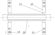
Fig. 3 is assisted rotating mechanism constructional drawing.
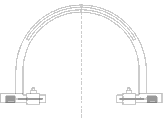
Fig. 4 (a) is inverted U hanger structure front view.
Fig. 4 (b) is inverted U hanger structure birds-eye view.
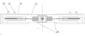
Fig. 4 (c) is suspender hold-down arm and telescopic arm structure schematic diagram.
Fig. 5 is vertical driving device structure schematic diagram.
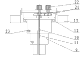
Wherein, 1 is inverted U suspender, 2 is assisted rotating mechanism, 3 is auxiliary wheel, 4 is I shape guide rail, 5 is horizontal drive wheel, 6 is horizontal drive motor, 7 for controlling casing, 8 is bearing support, 9 is square retracting cylinder, 10 is vertical leading screw, 11 is slide block, 12 is ball, 13 is connecting arm, 14 is bracing frame, 15 is support roller, 16 is friction driving roller, 17 is rotary drive motor, 18 is thimble, 19 is limiting stopper, 20 is arc orbit, 21 is gear, 22 is drive motor, 23 is roller, 24 is telescopic boom, 25 is hold-down arm, 26 is horizontal screw lead.
The specific embodiment
Below in conjunction with accompanying drawing, the invention will be further described.
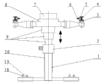
Fig. 1 is multiple degree of freedom automatic traveling cart system constructional drawing, wherein Fig. 1 (a) is front view, Fig. 1 (b) is left view, the present invention includes and control casing 7, controlling cover in casing 7 outer rims has bearing support 8, and the cross connecting arm 13(on bearing support 8 is as shown in Figure 2) by horizontal drive apparatus, be suspended on the I shape guide rail 4 of dolly both sides.Described horizontal drive apparatus comprises horizontal drive motor 6, horizontal drive wheel 5, auxiliary wheel 3, and horizontal drive wheel 5 is connected with horizontal drive motor 6, is stuck in the groove of I shape guide rail 4, and auxiliary wheel 3 is arranged on the below of I shape guide rail 4.Control casing 7 and be connected with assisted rotating mechanism 2 by vertical actuating device, form revolute pair.
Assisted rotating mechanism 2 as shown in Figure 3, comprises bracing frame 14, support roller 15, rotary drive motor 17, the friction driving roller 16 being connected with rotary drive motor 17; Arc orbit 20 on inverted U suspender 1 is arranged between support roller 15, and the friction driving roller 16 of assisted rotating mechanism 2 contacts with lower arc surface with the upper arc surface of inverted U suspender 1 respectively with bracing frame 14, and inverted U suspender 1 can be around x axle 0
o~ 45
opositive and negative both direction continuous rotation.
If Fig. 4 (a) is (b) as shown in (c), telescopic boom 24 on inverted U suspender 1 and hold-down arm 25 can be respectively under the effects of motor and horizontal screw lead 26, carry out horizontal extension, thimble 18 and limiting stopper 19 are used for restriction and fixing vehicle body, guarantee the safety in rotary course, thereby meet the requirement that multi-vehicle-type swinging cross is produced.
Fig. 5 is vertical driving device structure schematic diagram, comprise drive motor 22, retracting cylinder 9, vertical screw mandrel 10 and slide block 11, the drive motor 22 of controlling in casing 7 is connected with the slide block 11 of retracting cylinder 9 inside by vertical screw mandrel 10, and slide block 11 is rigidly connected with assisted rotating mechanism 2.Under the effect of motor and vertical leading screw 10, inverted U suspender 1 can move at vertical direction.
Described retracting cylinder 9 is step retracting cylinder, and inwall is provided with roller 23, guarantees that retracting cylinder 9 fore and aft motion are steady.
Retracting cylinder 9 forms revolute pair with bearing support 8 by ball 12, and by gear 21 transmissions, automatic traveling dolly can be around the positive and negative both direction of z axle continuous rotation within the scope of certain angle.
The working process of this embodiment is described below:
By thimble and limiting stopper, vehicle body is fixed on inverted U suspender, under the effect of horizontal drive wheel and auxiliary wheel, along track, vehicle body is transported to fixing work station point.If need to regulate height in fitting process, vertically leading screw, under the effect of motor, regulates the height of inverted U suspender by slide block, and now square retracting cylinder can guarantee the steady lifting of automatic traveling dolly.If need to regulate angle of assembling, main friction wheel, under the effect of motor, provides friction drive, drives inverted U suspender 0
o~ 45
oangular range in rotation, wherein supporting rollern contacts with arc orbit, provides support power and braking force, bracing frame has guaranteed the reliability of inverted U suspender.If need to regulate assembly direction, gear, under the effect of motor, makes inverted U suspender rotate within the scope of certain angle around the positive and negative both direction of z axle by square retracting cylinder.If the occasion of producing in multi-vehicle-type swinging cross, automatic traveling dolly, under the effect of motor and horizontal screw lead, by stretching of hold-down arm and telescopic arms, regulates suspender to be applicable to the conveying of different vehicle bodies.In addition, the parallel motion of automatic carriage, vertically mobile, around the rotation of x axle, separate, non-interference around four motions of rotation of z axle.
The concrete application approach of the present invention is a lot, and the above is only the preferred embodiment of the present invention, should be understood that; for those skilled in the art; under the premise without departing from the principles of the invention, can also make some improvement, these improvement also should be considered as protection scope of the present invention.
Claims (10)
1. a multiple degree of freedom automatic traveling dolly, comprise bearing support (8), on bearing support (8), be equipped with and control casing (7), in bearing support (8) outer rim, there is connecting arm (13), connecting arm (13) is suspended on the I shape guide rail (4) of dolly both sides by horizontal drive apparatus, horizontal direction degree of freedom is provided, it is characterized in that: control casing (7) and be connected with assisted rotating mechanism (2) by vertical actuating device, vertical direction degree of freedom is provided; Vertically actuating device top connects and composes revolute pair with bearing support (8), by running labyrinth around Z axis rotary freedom; Assisted rotating mechanism (2) comprises bracing frame (14), rotary drive motor (17), the friction driving roller (16) being connected with rotary drive motor (17); On bracing frame (14), hang with inverted U suspender (1), inverted U suspender (1) top arc orbit (20) contacts with friction driving roller (16), provides around X-axis rotary freedom.
2. multiple degree of freedom automatic traveling dolly according to claim 1, it is characterized in that: described vertical actuating device comprises drive motor (22), retracting cylinder (9), vertical screw mandrel (10) and slide block (11), wherein, control casing (7) and be connected by vertical screw mandrel (10) slide block (11) inner with retracting cylinder (9), slide block (11) is rigidly connected with assisted rotating mechanism (2).
3. multiple degree of freedom automatic traveling dolly according to claim 2, is characterized in that: described retracting cylinder (9) is step retracting cylinder, and inwall is provided with roller (23).
4. multiple degree of freedom automatic traveling dolly according to claim 2, it is characterized in that: described retracting cylinder (9) forms revolute pair with bearing support (8) by ball (12), drive motor (22) drives ball (12) and retracting cylinder (9) rotation by gear cluster (21).
5. multiple degree of freedom automatic traveling dolly according to claim 1 and 2, it is characterized in that: described assisted rotating mechanism (2) is equipped with two support rollers (15), the arc orbit (20) on inverted U suspender (1) is arranged between two support rollers (15).
6. multiple degree of freedom automatic traveling dolly according to claim 1 and 2, it is characterized in that: two footing of described inverted U suspender (1) are equipped with respectively hold-down arm (25), hold-down arm (25) two ends are connected with respectively telescopic boom (24) by motor and horizontal lead screw (26).
7. multiple degree of freedom automatic traveling dolly according to claim 6, is characterized in that: on described telescopic boom (24), put thimble (18) and limiting stopper (19) that fixation workpiece is housed.
8. multiple degree of freedom automatic traveling dolly according to claim 1 and 2, it is characterized in that: described horizontal drive apparatus comprises horizontal drive motor (6), horizontal drive wheel (5), horizontal drive wheel (5) is connected with horizontal drive motor (6), is stuck in the groove of I shape guide rail (4).
9. multiple degree of freedom automatic traveling dolly according to claim 8, is characterized in that: described horizontal drive apparatus is also provided with auxiliary wheel (3), is arranged on the below of I shape guide rail (4).
10. multiple degree of freedom automatic traveling dolly according to claim 1 and 2, is characterized in that: described connecting arm (13) is for cross.
Priority Applications (1)
| Application Number | Priority Date | Filing Date | Title |
|---|---|---|---|
| CN201310480360.1A CN103523478B (en) | 2013-10-15 | 2013-10-15 | A kind of multiple degrees of freedom automatic traveling dolly |
Applications Claiming Priority (1)
| Application Number | Priority Date | Filing Date | Title |
|---|---|---|---|
| CN201310480360.1A CN103523478B (en) | 2013-10-15 | 2013-10-15 | A kind of multiple degrees of freedom automatic traveling dolly |
Publications (2)
| Publication Number | Publication Date |
|---|---|
| CN103523478A true CN103523478A (en) | 2014-01-22 |
| CN103523478B CN103523478B (en) | 2016-08-10 |
Family
ID=49925914
Family Applications (1)
| Application Number | Title | Priority Date | Filing Date |
|---|---|---|---|
| CN201310480360.1A Active CN103523478B (en) | 2013-10-15 | 2013-10-15 | A kind of multiple degrees of freedom automatic traveling dolly |
Country Status (1)
| Country | Link |
|---|---|
| CN (1) | CN103523478B (en) |
Cited By (5)
| Publication number | Priority date | Publication date | Assignee | Title |
|---|---|---|---|---|
| CN106628895A (en) * | 2016-11-08 | 2017-05-10 | 天奇自动化工程股份有限公司 | Heavy-load self-propelled trolley conveying device |
| CN108820712A (en) * | 2018-06-26 | 2018-11-16 | 深圳市易玛克科技有限公司 | Single driving multi-stage expansion device |
| CN109083393A (en) * | 2018-09-11 | 2018-12-25 | 中建三局第建设工程有限责任公司 | The I-shaped guide rail of rack gear and elevating scaffold |
| CN109115873A (en) * | 2018-07-27 | 2019-01-01 | 中国工程物理研究院化工材料研究所 | A kind of annular multiaxis scanning equipment for complex configuration revolving body ultrasound detection |
| CN109592554A (en) * | 2018-12-29 | 2019-04-09 | 合肥市春华起重机械有限公司 | A kind of maintenance crane and rail-mounted gantry container crane |
Citations (6)
| Publication number | Priority date | Publication date | Assignee | Title |
|---|---|---|---|---|
| JPH03157259A (en) * | 1989-11-13 | 1991-07-05 | Nissei Ltd | Automatic unmanned trolley conveyor type conveying equipment |
| DE4326563A1 (en) * | 1993-08-07 | 1995-02-09 | Rainer F Tracksdorf | Conveying apparatus for vehicle bodies |
| CN201010327Y (en) * | 2006-12-31 | 2008-01-23 | 王树生 | Movable hanging device of three-part telescopic bogie truck |
| JP2010089903A (en) * | 2008-10-08 | 2010-04-22 | Nakanishi Metal Works Co Ltd | Carrier having tilt hanger |
| CN102424253A (en) * | 2011-08-16 | 2012-04-25 | 江苏天奇物流系统工程股份有限公司 | Automobile cart conveying system |
| CN102991979A (en) * | 2012-11-30 | 2013-03-27 | 湖北华昌达智能装备股份有限公司 | Self-propelling car system |
-
2013
- 2013-10-15 CN CN201310480360.1A patent/CN103523478B/en active Active
Patent Citations (6)
| Publication number | Priority date | Publication date | Assignee | Title |
|---|---|---|---|---|
| JPH03157259A (en) * | 1989-11-13 | 1991-07-05 | Nissei Ltd | Automatic unmanned trolley conveyor type conveying equipment |
| DE4326563A1 (en) * | 1993-08-07 | 1995-02-09 | Rainer F Tracksdorf | Conveying apparatus for vehicle bodies |
| CN201010327Y (en) * | 2006-12-31 | 2008-01-23 | 王树生 | Movable hanging device of three-part telescopic bogie truck |
| JP2010089903A (en) * | 2008-10-08 | 2010-04-22 | Nakanishi Metal Works Co Ltd | Carrier having tilt hanger |
| CN102424253A (en) * | 2011-08-16 | 2012-04-25 | 江苏天奇物流系统工程股份有限公司 | Automobile cart conveying system |
| CN102991979A (en) * | 2012-11-30 | 2013-03-27 | 湖北华昌达智能装备股份有限公司 | Self-propelling car system |
Cited By (7)
| Publication number | Priority date | Publication date | Assignee | Title |
|---|---|---|---|---|
| CN106628895A (en) * | 2016-11-08 | 2017-05-10 | 天奇自动化工程股份有限公司 | Heavy-load self-propelled trolley conveying device |
| CN108820712A (en) * | 2018-06-26 | 2018-11-16 | 深圳市易玛克科技有限公司 | Single driving multi-stage expansion device |
| CN109115873A (en) * | 2018-07-27 | 2019-01-01 | 中国工程物理研究院化工材料研究所 | A kind of annular multiaxis scanning equipment for complex configuration revolving body ultrasound detection |
| CN109115873B (en) * | 2018-07-27 | 2020-11-03 | 中国工程物理研究院化工材料研究所 | Annular multi-axis scanning device for ultrasonic detection of complex-configuration revolving body |
| CN109083393A (en) * | 2018-09-11 | 2018-12-25 | 中建三局第建设工程有限责任公司 | The I-shaped guide rail of rack gear and elevating scaffold |
| CN109592554A (en) * | 2018-12-29 | 2019-04-09 | 合肥市春华起重机械有限公司 | A kind of maintenance crane and rail-mounted gantry container crane |
| CN109592554B (en) * | 2018-12-29 | 2020-05-05 | 合肥市春华起重机械有限公司 | Maintenance crane and rail type gantry container crane |
Also Published As
| Publication number | Publication date |
|---|---|
| CN103523478B (en) | 2016-08-10 |
Similar Documents
| Publication | Publication Date | Title |
|---|---|---|
| CN102530534B (en) | Air suspension lifter | |
| CN103523478A (en) | Multi-freedom-degree self-propelled trolley | |
| CN202499532U (en) | Air suspension lifter | |
| CN110948206A (en) | Bogie assembling and forming process and bolster and side frame assembling machine | |
| CN104816293B (en) | A kind of mobile mechanical arm of eight degrees of freedom | |
| CN203845710U (en) | Automobile production line welding station switching device | |
| CN202499655U (en) | Travelling lifting appliance | |
| CN204724750U (en) | A kind of planer-type C-type steel piling system | |
| CN102408069A (en) | Rail-type gantry crane | |
| CN203638615U (en) | Cross-rail transport assembly vehicle | |
| CN103662704A (en) | Rail-spanning transportation assembly wagon | |
| CN205764526U (en) | For welding the dolly of clamping-rail trolley conductor bracket | |
| CN202877793U (en) | Turnover machine for welding frame of semitrailer | |
| CN210103168U (en) | Suspension type package transfer trolley and automatic package transfer system | |
| CN206767468U (en) | Chassis lowering or hoisting gear based on stay-supported encoder | |
| CN106743250A (en) | A kind of single pile movement system | |
| CN111056247A (en) | Elevator for rail transfer of EMS (energy management system) conveying trolley | |
| CN103722114B (en) | Hot die forging press forging conveying arrangement | |
| CN214054157U (en) | Multi-degree-of-freedom gantry welding machine for large pipe fittings | |
| CN105523484B (en) | A kind of tunnel measure of relief and its device | |
| CN204939645U (en) | Electroplating traveling crane | |
| CN204529191U (en) | Remote controlled pile tube Lift-on/Lift-off System | |
| CN209480562U (en) | A kind of chain push-and-pull type injection molding machine mould replacing trolley | |
| CN207695905U (en) | A kind of steel tower welding center | |
| CN207375273U (en) | A kind of load-balancing device of steel rail translation system |
Legal Events
| Date | Code | Title | Description |
|---|---|---|---|
| C06 | Publication | ||
| PB01 | Publication | ||
| C10 | Entry into substantive examination | ||
| SE01 | Entry into force of request for substantive examination | ||
| C14 | Grant of patent or utility model | ||
| GR01 | Patent grant |