JP2010089903A - Carrier having tilt hanger - Google Patents
Carrier having tilt hanger Download PDFInfo
- Publication number
- JP2010089903A JP2010089903A JP2008261227A JP2008261227A JP2010089903A JP 2010089903 A JP2010089903 A JP 2010089903A JP 2008261227 A JP2008261227 A JP 2008261227A JP 2008261227 A JP2008261227 A JP 2008261227A JP 2010089903 A JP2010089903 A JP 2010089903A
- Authority
- JP
- Japan
- Prior art keywords
- hanger
- trolley
- rotation
- tilt
- center
- Prior art date
- Legal status (The legal status is an assumption and is not a legal conclusion. Google has not performed a legal analysis and makes no representation as to the accuracy of the status listed.)
- Granted
Links
Images


Abstract
Description
本発明はレールに沿って物品を搬送するチルトハンガーを備えた搬送車に関するものであり、より詳しくは、搬送する物品の傾きを容易に変更することができるとともに、搬送車を軽量なものとして搬送装置の耐久性を向上し、さらに、製造コストを低減することができるチルトハンガーを備えた搬送車に関するものである。 The present invention relates to a transport vehicle provided with a tilt hanger that transports an article along a rail, and more specifically, the tilt of the article to be transported can be easily changed, and the transport vehicle is transported as a lightweight one. The present invention relates to a transport vehicle including a tilt hanger capable of improving the durability of the apparatus and further reducing the manufacturing cost.
従来、自動車等の工業製品の製造現場では、搬送装置により一定の搬送ラインで物品(車体等)を搬送して各工程を順次行い、工業製品を効率よく製造する方法が用いられている。
また、このような製造現場においては、各工程により作業の対象となる物品の部分が異なるため、各工程において作業者が作業しやすいように搬送中の物品を傾斜させることができる搬送車を備えた搬送装置が使用されることもある。
2. Description of the Related Art Conventionally, in manufacturing sites for industrial products such as automobiles, a method for efficiently manufacturing industrial products by transporting articles (car bodies, etc.) along a certain transport line by a transport device and sequentially performing each process.
Moreover, in such a manufacturing site, since the parts of articles to be worked are different in each process, a transport vehicle that can tilt the goods being transported so that an operator can easily work in each process is provided. In some cases, a different transport device is used.
トロリコンベアにより搬送中の搬送物を傾斜させることができるものとして、第一レールに案内されるチエン、および第二レールに案内され且つ前記チエンにより進行されるトロリからなるトロリコンベヤの前記トロリに一次ハンガーが設けられ、一次ハンガーに二次ハンガーが進行方向に対して横断方向に旋回自在に設けられてなるトロリコンベヤの旋回装置において、一次ハンガーに正転用カムローラおよび逆転用カムローラを有するアームが軸支され、この正転用カムローラに対しては正転用カム通路が、逆転用カムローラに対しては逆転用カム通路がそれぞれ係合可能にコンベヤの進行方向の設定位置に配設され、而してカムローラがカム通路に係合することにより生ずる前記アームの旋回動は公知の伝動機構を介して二次ハンガーのアーチ部分に伝達される如く構成されていることを特徴とするトロリコンベヤがある(例えば、特許文献1)。 As the thing which can incline the conveyed product currently conveyed by the trolley conveyor, it is primary to the said trolley of the trolley conveyor which consists of the chain guided to the 1st rail, and the trolley which is guided to the 2nd rail and advances by the said chain. In a trolley conveyor swivel device in which a hanger is provided and a secondary hanger is provided on the primary hanger so as to be pivotable in a direction transverse to the traveling direction, an arm having a forward rotation cam roller and a reverse rotation cam roller is pivotally supported on the primary hanger. A forward cam path is arranged for the forward cam roller and a reverse cam path is engaged with the reverse cam roller at a set position in the moving direction of the conveyor. The swivel movement of the arm caused by engaging with the cam passage is a secondary hanger via a known transmission mechanism. There is a trolley conveyor, characterized in that it is constructed as being transmitted to the arch portion (e.g., Patent Document 1).
特許文献1のものは、上記構成により、コンベヤに搭載された物品に対して作業員は立ったままの姿勢で横方向から作業ができ、作業が容易であるとともに、部品が落下したりする危険がなく、また正転、逆転用カム等はハンガーの上部側方に設けられているので、作業員がこれらに当たる危険がなく、これらの設置により作業環境が悪化されないものである。 With the configuration described in Patent Document 1, the worker can work from the side in a standing posture with respect to the articles mounted on the conveyor, the work is easy, and there is a risk that the parts may fall. In addition, since the forward rotation and reverse rotation cams are provided on the upper side of the hanger, there is no danger of workers hitting them, and their installation does not deteriorate the work environment.
ここで、特許文献1のものは一定形状のハンガーに搬送物を支持させて搬送するものであるため、種類によって大きさの異なるもの、例えば自動車を搬送する場合、一定範囲内のサイズの自動車を搬送するために高さ方向及び幅方向ともに十分な間隔をもたせたハンガーとすることが必要である。しかし、このような必要以上の高さのあるハンガーに一般的若しくは比較的小さなサイズの自動車を載置すると、自動車及びハンガーの重心がハンガーの回転中心よりも下方に位置することとなり、このようなハンガーを回転させるためには大きな駆動力が必要となるため、必然的に回転駆動機は重量化する。搬送車が重量化すると搬送装置全体の製造コストを増大させ、耐久性も悪くなる要因となる。また、この重量化した搬送車に、ハンガーを昇降移動可能とする昇降部材を設ける場合は、搬送中に生ずる慣性力等も考慮して揺動防止機能をより高めた昇降部材とする必要が生ずる。 Here, since the thing of patent document 1 is what supports a conveyed product on the hanger of a fixed shape, and conveys what differs in size according to a kind, for example, a car, a car of a size within a fixed range is used. It is necessary to provide a hanger with sufficient spacing in both the height direction and the width direction for transport. However, if a general or relatively small size automobile is placed on a hanger that is higher than necessary, the center of gravity of the automobile and the hanger will be located below the center of rotation of the hanger. Since a large driving force is required to rotate the hanger, the rotational driving machine inevitably becomes heavy. If the transport vehicle becomes heavier, the manufacturing cost of the entire transport device is increased and the durability is also deteriorated. In addition, when a lifting member that can move the hanger up and down is provided on the weighted transport vehicle, it is necessary to use a lifting member that has a higher swing prevention function in consideration of inertial force and the like generated during transportation. .
そこで、本発明が解決しようとするものは、レールに沿って搬送物を搬送する際、搬送物が載置されたハンガーを比較的小さな力で傾斜させることができるチルトハンガーを備えた搬送車を提供する点にある。 Therefore, the present invention intends to solve a transport vehicle equipped with a tilt hanger that can tilt a hanger on which a transported object is placed with a relatively small force when transporting a transported object along a rail. The point is to provide.
上述の課題を解決するために、本発明に係るチルトハンガーを備えた搬送車は、搬送レールに沿って走行するトロリと、該トロリに取り付けられるとともに、略円弧状の回転ガイド部と搬送物を支持する支持部とを有するハンガーと、前記回転ガイド部の円弧中心点を回転中心として、前記ハンガーを回動させる回転駆動機とを備え、前記支持部に前記搬送物の重心を前記回転ガイド部の回転中心に近づける位置調整手段を設けてなることを特徴とするものである。 In order to solve the above-described problems, a transport vehicle equipped with a tilt hanger according to the present invention includes a trolley that travels along a transport rail, a trolley that is attached to the trolley, a substantially arc-shaped rotation guide portion, and a transport object. A hanger having a support part to support, and a rotation driving device for rotating the hanger around a circular arc center point of the rotation guide part, and the rotation guide part provides a center of gravity of the transported object to the support part. It is characterized in that it is provided with a position adjusting means for bringing it closer to the center of rotation.
ここで、前記ハンガーが、該ハンガーを前記トロリに対して昇降自在とする昇降部材を介して、前記トロリに取り付けられてなると好ましい。 Here, it is preferable that the hanger is attached to the trolley via an elevating member that allows the hanger to move up and down with respect to the trolley.
また、前記回転駆動機が、前記回転ガイド部に圧接する円柱状の回転ローラーを備えてなると好ましい。 Moreover, it is preferable that the rotary drive machine includes a cylindrical rotary roller that is in pressure contact with the rotary guide portion.
さらに、前記位置調整手段が、前記ハンガーの両端部に設けた上下方向軸の貫通孔に挿通され昇降可能状態のアタッチと、該アタッチ及び前記ハンガーの両端部に略水平に設けた固定用孔に挿嵌する固定ピンとを備えてなると好ましい。 Furthermore, the position adjusting means is inserted into the through-holes of the vertical axis provided at both ends of the hanger and is attached to the liftable state, and the fixing holes provided substantially horizontally at both ends of the attach and the hanger. It is preferable that a fixing pin to be inserted is provided.
請求項1に係るチルトハンガーを備えた搬送車によれば、小さな回転駆動力でも搬送物を載置したハンガーを回転させることができる。また、ハンガーの回転によっても積載物のトロリとの相対位置が大きくずれることがなく、作業位置を固定することができる。 According to the conveyance vehicle provided with the tilt hanger according to the first aspect, the hanger on which the conveyance object is placed can be rotated even with a small rotational driving force. Further, the work position can be fixed without the relative position of the load with the trolley being greatly displaced even by rotation of the hanger.
また、前記ハンガーが、該ハンガーを前記トロリに対して昇降自在とする昇降部材を介して、前記トロリに取り付けられてなるものによれば、上記効果に加えて、回転駆動装置を軽量なものとし、これを支持する昇降部材及び昇降駆動装置も軽量化することができる。その結果、搬送車全体の軽量化することで搬送装置の耐久性を向上するとともに、製造コストを低廉化することができる。 Further, according to the hanger attached to the trolley via an elevating member that allows the hanger to move up and down with respect to the trolley, in addition to the above effects, the rotary drive device is lightweight. Also, the elevating member and the elevating drive device that support the elevating member can be reduced in weight. As a result, the weight of the entire transport vehicle can be reduced, so that the durability of the transport device can be improved and the manufacturing cost can be reduced.
さらに、前記回転駆動機が、前記回転ガイド部に圧接する円柱状の回転ローラーを備えてなるものによれば、騒音、製造コストの面で有利なものとすることができる。また、ギアなどの駆動手段に比べて回転振動が少なく、スムーズに行動することができる。 Further, according to the rotary drive machine provided with a cylindrical rotary roller that is in pressure contact with the rotary guide portion, it can be advantageous in terms of noise and manufacturing cost. In addition, there is less rotational vibration than a driving means such as a gear, and it can act smoothly.
さらにまた、前記位置調整手段が、前記ハンガーの両端部に設けた上下方向軸の貫通孔に挿通され昇降可能状態のアタッチと、該アタッチ及び前記ハンガーの両端部に略水平に設けた固定用孔に挿嵌する固定ピンとを備えてなるものよれば、簡易な方法で位置調整及び固定することができ、搬送車を軽量なものとすることができる。 Still further, the position adjusting means is inserted through the through-holes of the vertical axis provided at both ends of the hanger and is capable of moving up and down, and the fixing holes provided substantially horizontally at both ends of the attach and the hanger According to the present invention, it is possible to adjust and fix the position by a simple method, and to reduce the weight of the transport vehicle.
次に、本発明の実施形態を添付図面に基づいて説明するが、本発明は添付図面に示された形態に限定されず、特許請求の範囲に記載の要件を満たす実施形態の全てを含むものである。なお、本実施形態の説明において、図2に示す搬送車1の進行方向Aを前方とし、前方を向いて左右を決めるものとする。 Next, embodiments of the present invention will be described with reference to the accompanying drawings. However, the present invention is not limited to the embodiments shown in the accompanying drawings, and includes all the embodiments that satisfy the requirements described in the claims. . In the description of this embodiment, it is assumed that the traveling direction A of the transport vehicle 1 shown in FIG.
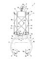
図1〜図6は本実施形態に係るチルトハンガーを備えた搬送車の構成を示す説明図であり、図1は本実施形態に係るチルトハンガーを備えた搬送車の正面図、図2は右側面図、図3は本実施形態に係る位置調整手段の構成を示す部分拡大図であり、(a)は位置調整前の状態を示す正面図、(b)は位置調整後の状態を示す正面図、図4は搬送物を載置した状態(位置調整前)を示す部分拡大図、図5は搬送物の位置調整を行った状態を示す部分拡大図、図6は搬送物傾斜状態を示す正面図である。また、図中に示す符号1は搬送車、2はトロリ、3は昇降部材、4はハンガー、5は回転駆動機である。 1 to 6 are explanatory views showing a configuration of a transport vehicle including a tilt hanger according to the present embodiment. FIG. 1 is a front view of the transport vehicle including the tilt hanger according to the present embodiment. FIG. FIG. 3 is a partial enlarged view showing the configuration of the position adjusting means according to this embodiment, (a) is a front view showing a state before position adjustment, and (b) is a front view showing a state after position adjustment. 4 is a partially enlarged view showing a state (before position adjustment) in which a conveyed product is placed, FIG. 5 is a partially enlarged view showing a state in which the position of the conveyed product is adjusted, and FIG. 6 shows an inclined state of the conveyed product. It is a front view. In the figure, reference numeral 1 denotes a transport vehicle, 2 denotes a trolley, 3 denotes an elevating member, 4 denotes a hanger, and 5 denotes a rotary drive machine.
図1及び図2に示す本実施形態に係るチルトハンガーを備えた搬送車1の構成を説明する。 A configuration of the transport vehicle 1 including the tilt hanger according to the present embodiment illustrated in FIGS. 1 and 2 will be described.
搬送レールRは、断面視I型鋼で形成されるとともに、各作業場所をつないで設けられており、これに沿って搬送車1が走行して載置した搬送物Pを搬送する。 The transport rail R is formed of cross-sectional I-shaped steel, and is provided by connecting each work place. The transport vehicle 1 travels along the transport rail P and transports the transported object P placed thereon.
搬送車1は、搬送レールRに沿って走行するトロリ2と、トロリ2により下方に懸架される昇降部材3と、昇降部材3を介して昇降可能に前記トロリ2に取り付けられるとともに、略円弧状の回転ガイド部4aと搬送物Pを支持する支持部4bとを有するハンガー4とを備えてなる。また、昇降部材3の下部にはハンガー4を回転させる回転駆動機5を備え、ハンガー4を搬送車1の進行方向軸回りに回転自在としている。
The transport vehicle 1 is attached to the
トロリ2は、併設された駆動装置8により搬送レールR上で回転する搬送ローラー2aと、搬送レールRの両側面に圧接するガイドローラー2b、2b、2b、2bとを備えて、搬送レールRに沿って自走する。また、トロリ2には搬送物Pを載置するハンガー4が昇降部材3により、トロリ2に対して昇降自在に取り付けられている。連結部材により連結された2対のトロリ2,2が、搬送車1の前側及び後側に夫々、合計2組4体配置され、後側に配置されたトロリ2には駆動装置8が設けられている。
The
昇降部材3は、4体のトロリ2、2、2、2により懸架され、下端には搬送物Pを載置するハンガー4が取り付けられている。また、昇降部材3は、上フレーム3aと下フレーム3dを上揺動防止部材3b及び下揺動防止部材3cにより連結して構成されている。
上揺動防止部材3b及び下揺動防止部材3cは、中間連結部分及び上下フレーム連結部分で、一方向にのみ回動することができる構成とされることにより、水平方向における他の方向へのハンガー4の揺動を防止できる。この上揺動防止部材3b及び下揺動防止部材3cを進行方向及び左右方向に対して揺動を防止するように合計4体配置して、前後左右方向へのハンガー4の揺動を防止できるものとしている。
また、この昇降部材3を備えた搬送車1では昇降ベルト3eを巻上機3fで巻き上げることにより、ハンガー4を上昇させることができ、反対に昇降ベルト3eを繰り出すことにより、ハンガー4を下降させることができる。この昇降移動中及び昇降移動後においても上記作用により、ハンガー4の前後左右方向への揺動を規制して安定して搬送物Pを搬送することができる。
The
The upper
Moreover, in the conveyance vehicle 1 provided with this raising / lowering
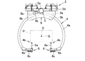
ハンガー4は、略C字状の回転ガイド部4aと、両端に位置する支持部4bとよりなり、昇降部材3の下端に固定されたハンガー取付部9に設けられた上側ガイドローラー9a及び下側ガイドローラー9bにより回動自在に支持されている。上側ガイドローラー9a及び下側ガイドローラー9bに係合する回転ガイド部4aは円弧状となっていることにより、回転駆動機5の回転ローラー5aの回転をハンガー4にスムーズに伝動し、支持部4bで支持される搬送物Pを搬送方向に対して垂直面において円滑に傾斜させることができる。
支持部4bには位置調整手段6が設けられ、この位置調整手段のより載置した搬送物Pの重心Gをよりハンガー4の回転中心Cに近づけて搬送物を傾斜させる。搬送物Pの重心Gをハンガー4の回転中心Cに近づけることで比較的小さな力でハンガー4を回転させることができ、ハンガー4の回転駆動機5を簡易且つ軽量なものとすることができる。
また、ハンガー4の重心はハンガー4の回転中心C近傍に位置しているため、搬送物Pの重心Gをハンガー4の回転中心Cに近づけることで、ハンガー4及び搬送物Pの重心をハンガー4の回転中心Cに近づけることとなり、ハンガー4の回転に要する力を低減させるための搬送物Pの位置調整が容易となるが、このような構成とせず、回転ガイド部4aと支持部4bを有するものであれば他の構成としたものでもよい。
The
Position adjustment means 6 is provided in the
Further, since the center of gravity of the
回転駆動機5は、ハンガー4に圧接する回転ローラー5aをモーター5bにより回転させてハンガー4を回転させる。このとき、搬送物Pの重心Gはハンガーの回転中心Cの近くに位置することにより、ハンガー4及び搬送物Pの重心がハンガー4の回転中心C近傍に位置することとなり、ハンガー4を回転させる回転駆動機5に必要とされる回転力は比較的小さいものとなっている。
The
位置調整手段6は、図3に示すように、ハンガー4の両端に設けた貫通孔にアタッチ6aを挿通させ、アタッチ6aとハンガーとを固定するばね6cにより付勢される固定ピン6bを設けてなる。アタッチ6aの上端には搬送物Pを載置する載置部が設けられている。この載置部は、ハンガー4が傾斜した際に搬送物Pが転落などしないように滑り止めが備えられているが、簡易固定できるものでハンガー4に搬送物Pを固定して搬送するものとしてもよい。
As shown in FIG. 3, the position adjusting means 6 is provided with a fixing
また、実施形態に係るチルトハンガーを備えた搬送車1の搬送動作(搬送車1の走行、昇降部材3の昇降、及びハンガーの回動)は昇降部材3に備えた制御盤7により制御される。
Further, the transport operation (travel of the transport vehicle 1, lifting and lowering of the lifting
以下、図4〜図7に沿って本実施形態に係るチルトハンガーを備えた搬送車1の搬送動作について説明する。 Hereinafter, the transport operation of the transport vehicle 1 including the tilt hanger according to the present embodiment will be described with reference to FIGS.
まず、図4に示すように、搬送物Pを載置するには、昇降部材3によりハンガー4の高さを所定の載置高さとし、ハンガー4は回転させず、開口部を真下に位置した状態とし、ハンガー4のアタッチ6aはハンガー4の内側への突出が最小となるように位置させて搬送物Pを載置する。これにより、積載時にはハンガー4と搬送物Pの間には十分な余裕があり、安全に積載することができる。
次に、図5に示すように搬送物Pの位置調整を行う。最下位置にあるアタッチ6aを地上側に設置した外部装置(図示せず)により、アタッチ6aを所定高さまで押し上げる。搬送物Pの重心Gがハンガー4の回転中心Cに近づいた状態で固定ピン6bをハンガー4及びアタッチ6aに設けた貫通孔に挿通してアタッチ6aをハンガー4に固定する。
この位置調整により、搬送物Pの重心Gはハンガー4の回転中心Cに近づき、搬送物Pを傾斜させるために必要となる力を小さいものとすることができる。
また、アタッチ6aは取り外し容易に構成されているため、搬送物が変更された際には、搬送物に合わせた高さとすることができるアタッチ6aに交換することで随時対応することができる。
First, as shown in FIG. 4, in order to place the conveyed product P, the height of the
Next, the position of the conveyed product P is adjusted as shown in FIG. The
By this position adjustment, the center of gravity G of the conveyed product P approaches the rotation center C of the
Moreover, since the
搬送中、搬送物Pの下面及びその付近について作業する場合等、必要に応じて図6に示すように、ハンガー4を回転駆動機5により所定角度回転させ、搬送物Pを進行方向軸回りに傾斜させる。搬送物Pはハンガー4に載置した後にアタッチ6aの昇降により位置調整され、搬送物の重心Gがハンガーの回転中心C近傍に位置して支持されているため、搬送物及びハンガーの重心からハンガーの回転中心Cまでの距離に比例する、ハンガーを回転させるために必要となる力を小さくすることができる。
When working on the lower surface of the conveyed product P and its vicinity during conveyance, as shown in FIG. 6, the
なお、本実施形態においては、ハンガーが昇降部材を介してトロリに懸架されているが、この構成に関わらず、ハンガーを設けたトロリが搬送レールに沿って走行する搬送装置であればよく、例えば、搬送レール上を走行するトロリの上方に直接支持されるハンガーに位置調整手段を設けた構成としてもよい。
また、回転駆動機は圧接することでハンガーを回転させることができるフリクションローラーにより、ハンガーを回転させるものとしているが、他の構成、例えばギア等を用いた構成としてもよい。
さらに、アタッチは取り外し自在、且つ固定用の貫通孔を1個設けて構成したが、取り外し不能に設けられたものでもよく、また、搬送物のサイズに合わせて段階的に高さを調整して簡易固定できるようにしたものであってもよい。
さらにまた、位置調整手段として、搬送物の重心Gを自動的に判断する装置を併用して搬送物の位置調整を行うものとしてもよい。
In this embodiment, the hanger is suspended on the trolley via the lifting member, but regardless of this configuration, the trolley provided with the hanger may be a transport device that travels along the transport rail. The hanger supported directly above the trolley traveling on the transport rail may be provided with a position adjusting means.
In addition, although the rotary drive machine is configured to rotate the hanger by a friction roller that can rotate the hanger by press-contacting, other configurations such as a configuration using a gear or the like may be used.
In addition, the attachment is detachable and has a fixed through-hole. However, the attachment may be non-removable, and the height can be adjusted step by step according to the size of the transported object. It may be one that can be simply fixed.
Furthermore, the position adjustment means may be used in combination with a device that automatically determines the center of gravity G of the conveyed object to adjust the position of the conveyed object.
1 搬送車
2 トロリ
2a 搬送ローラー
2b ガイドローラー
3 昇降部材
3a 上フレーム
3b 上揺動防止部材
3c 下揺動防止部材
3d 下フレーム
3e 昇降ベルト
3f 巻上機
4 ハンガー
4a 回転ガイド部
4b 支持部
5 回転駆動機
5a 回転ローラー
5b モーター
6 位置調整手段
6a アタッチ
6b 固定ピン
6c ばね
7 制御盤
8 駆動装置
9 ハンガー取付部
9a 上側ガイドローラー
9b 下側ガイドローラー
A 進行方向
C 回転中心
G 搬送物の重心
P 搬送物
R 搬送レール
DESCRIPTION OF SYMBOLS 1
Claims (4)
該トロリに取り付けられるとともに、略円弧状の回転ガイド部と搬送物を支持する支持部とを有するハンガーと、
前記回転ガイド部の円弧中心点を回転中心として、前記ハンガーを回動させる回転駆動機とを備え、
前記支持部に前記搬送物の重心を前記回転ガイド部の回転中心に近づける位置調整手段を設けてなることを特徴とするチルトハンガーを備えた搬送車。 A trolley that runs along the transport rail;
A hanger attached to the trolley and having a substantially arcuate rotation guide part and a support part for supporting a conveyed product,
A rotation drive machine that rotates the hanger around the arc center point of the rotation guide portion as a rotation center;
A transport vehicle equipped with a tilt hanger, wherein the support portion is provided with position adjusting means for bringing the center of gravity of the transported object closer to the rotation center of the rotation guide portion.
The position adjusting means is inserted into through-holes in the vertical axis provided at both ends of the hanger so as to be movable up and down, and is inserted into fixing holes provided substantially horizontally at both ends of the attach and the hanger. The conveyance vehicle provided with the tilt hanger of any one of Claims 1-3 provided with the fixed pin to perform.
Priority Applications (1)
| Application Number | Priority Date | Filing Date | Title |
|---|---|---|---|
| JP2008261227A JP5320963B2 (en) | 2008-10-08 | 2008-10-08 | Transport vehicle with tilt hanger |
Applications Claiming Priority (1)
| Application Number | Priority Date | Filing Date | Title |
|---|---|---|---|
| JP2008261227A JP5320963B2 (en) | 2008-10-08 | 2008-10-08 | Transport vehicle with tilt hanger |
Publications (2)
| Publication Number | Publication Date |
|---|---|
| JP2010089903A true JP2010089903A (en) | 2010-04-22 |
| JP5320963B2 JP5320963B2 (en) | 2013-10-23 |
Family
ID=42253034
Family Applications (1)
| Application Number | Title | Priority Date | Filing Date |
|---|---|---|---|
| JP2008261227A Active JP5320963B2 (en) | 2008-10-08 | 2008-10-08 | Transport vehicle with tilt hanger |
Country Status (1)
| Country | Link |
|---|---|
| JP (1) | JP5320963B2 (en) |
Cited By (3)
| Publication number | Priority date | Publication date | Assignee | Title |
|---|---|---|---|---|
| CN103523478A (en) * | 2013-10-15 | 2014-01-22 | 南京航空航天大学 | Multi-freedom-degree self-propelled trolley |
| KR101474693B1 (en) | 2014-06-11 | 2014-12-19 | 노현구 | Tilting apparatus of conveyor for solt loader |
| CN112926919A (en) * | 2021-03-08 | 2021-06-08 | 太原重工股份有限公司 | Intelligent management library for long timber and management method thereof |
Citations (5)
| Publication number | Priority date | Publication date | Assignee | Title |
|---|---|---|---|---|
| JPS5293171U (en) * | 1976-01-05 | 1977-07-12 | ||
| JPH03223022A (en) * | 1990-01-25 | 1991-10-02 | Nakanishi Kinzoku Kogyo Kk | Trolley conveyor |
| JPH0485163A (en) * | 1990-07-26 | 1992-03-18 | Toyota Motor Corp | Motor-driven traveling hanger |
| JPH1035841A (en) * | 1997-04-11 | 1998-02-10 | Toyota Koki Kk | Concrete product reversing device |
| JP2003276829A (en) * | 2002-03-27 | 2003-10-02 | Murata Mfg Co Ltd | Work conveying device and work conveying method |
-
2008
- 2008-10-08 JP JP2008261227A patent/JP5320963B2/en active Active
Patent Citations (5)
| Publication number | Priority date | Publication date | Assignee | Title |
|---|---|---|---|---|
| JPS5293171U (en) * | 1976-01-05 | 1977-07-12 | ||
| JPH03223022A (en) * | 1990-01-25 | 1991-10-02 | Nakanishi Kinzoku Kogyo Kk | Trolley conveyor |
| JPH0485163A (en) * | 1990-07-26 | 1992-03-18 | Toyota Motor Corp | Motor-driven traveling hanger |
| JPH1035841A (en) * | 1997-04-11 | 1998-02-10 | Toyota Koki Kk | Concrete product reversing device |
| JP2003276829A (en) * | 2002-03-27 | 2003-10-02 | Murata Mfg Co Ltd | Work conveying device and work conveying method |
Cited By (4)
| Publication number | Priority date | Publication date | Assignee | Title |
|---|---|---|---|---|
| CN103523478A (en) * | 2013-10-15 | 2014-01-22 | 南京航空航天大学 | Multi-freedom-degree self-propelled trolley |
| KR101474693B1 (en) | 2014-06-11 | 2014-12-19 | 노현구 | Tilting apparatus of conveyor for solt loader |
| CN112926919A (en) * | 2021-03-08 | 2021-06-08 | 太原重工股份有限公司 | Intelligent management library for long timber and management method thereof |
| CN112926919B (en) * | 2021-03-08 | 2024-03-22 | 太原重工股份有限公司 | Long material intelligent management library and management method thereof |
Also Published As
| Publication number | Publication date |
|---|---|
| JP5320963B2 (en) | 2013-10-23 |
Similar Documents
| Publication | Publication Date | Title |
|---|---|---|
| JP5018598B2 (en) | Lifting type overhead carrier | |
| JP2006021858A (en) | Elevating/lowering and conveying device | |
| JP2017105223A (en) | Work reversing-carrying device | |
| JP5320963B2 (en) | Transport vehicle with tilt hanger | |
| JP2009083953A (en) | Transport device | |
| JP3695005B2 (en) | Connecting structure of elevating belt in transport cart | |
| JP4899989B2 (en) | Spare tire transfer device | |
| JP2019059380A (en) | Plate member conveyance dolly | |
| JP4244634B2 (en) | Transport device | |
| JP2017100812A (en) | Flip-up type conveyor device | |
| JP7134834B2 (en) | Rocker panel conveyor | |
| JP4052173B2 (en) | Transportation equipment using moving objects | |
| JP2009023811A (en) | Tilting type truck frame conveying device | |
| JP4122794B2 (en) | Hanging transfer equipment | |
| KR20070060274A (en) | Hanger apparatus to convey side assembly for automobile | |
| JP6385229B2 (en) | Rail spacing adjustment device | |
| JPH0318100Y2 (en) | ||
| JPH0739866Y2 (en) | Transport device using self-propelled body | |
| JP2000203419A (en) | Single-rail carrying device | |
| JP3086461U (en) | Transport device and traveling body | |
| JP3931837B2 (en) | Transportation equipment using mobile objects | |
| JP2008239292A (en) | Transfer device | |
| JP5168502B2 (en) | Horizontal maintenance conveyor | |
| JPH05193498A (en) | Carrier device for automotive door | |
| JPH07315218A (en) | Transport device using movement body |
Legal Events
| Date | Code | Title | Description |
|---|---|---|---|
| A621 | Written request for application examination |
Free format text: JAPANESE INTERMEDIATE CODE: A621 Effective date: 20110805 |
|
| A977 | Report on retrieval |
Free format text: JAPANESE INTERMEDIATE CODE: A971007 Effective date: 20130325 |
|
| A131 | Notification of reasons for refusal |
Free format text: JAPANESE INTERMEDIATE CODE: A131 Effective date: 20130402 |
|
| A521 | Request for written amendment filed |
Free format text: JAPANESE INTERMEDIATE CODE: A523 Effective date: 20130528 |
|
| TRDD | Decision of grant or rejection written | ||
| A01 | Written decision to grant a patent or to grant a registration (utility model) |
Free format text: JAPANESE INTERMEDIATE CODE: A01 Effective date: 20130618 |
|
| A61 | First payment of annual fees (during grant procedure) |
Free format text: JAPANESE INTERMEDIATE CODE: A61 Effective date: 20130701 |
|
| R150 | Certificate of patent or registration of utility model |
Ref document number: 5320963 Country of ref document: JP Free format text: JAPANESE INTERMEDIATE CODE: R150 Free format text: JAPANESE INTERMEDIATE CODE: R150 |
|
| R250 | Receipt of annual fees |
Free format text: JAPANESE INTERMEDIATE CODE: R250 |
|
| R250 | Receipt of annual fees |
Free format text: JAPANESE INTERMEDIATE CODE: R250 |
|
| R250 | Receipt of annual fees |
Free format text: JAPANESE INTERMEDIATE CODE: R250 |
|
| R250 | Receipt of annual fees |
Free format text: JAPANESE INTERMEDIATE CODE: R250 |
|
| R250 | Receipt of annual fees |
Free format text: JAPANESE INTERMEDIATE CODE: R250 |
|
| R250 | Receipt of annual fees |
Free format text: JAPANESE INTERMEDIATE CODE: R250 |
|
| R250 | Receipt of annual fees |
Free format text: JAPANESE INTERMEDIATE CODE: R250 |
|
| R250 | Receipt of annual fees |
Free format text: JAPANESE INTERMEDIATE CODE: R250 |