CN103484981A - Combing machine - Google Patents
Combing machine Download PDFInfo
- Publication number
- CN103484981A CN103484981A CN201310222869.6A CN201310222869A CN103484981A CN 103484981 A CN103484981 A CN 103484981A CN 201310222869 A CN201310222869 A CN 201310222869A CN 103484981 A CN103484981 A CN 103484981A
- Authority
- CN
- China
- Prior art keywords
- main pipeline
- combing
- combing machine
- suction channel
- noil
- Prior art date
- Legal status (The legal status is an assumption and is not a legal conclusion. Google has not performed a legal analysis and makes no representation as to the accuracy of the status listed.)
- Pending
Links
Images


Classifications
-
- D—TEXTILES; PAPER
- D01—NATURAL OR MAN-MADE THREADS OR FIBRES; SPINNING
- D01G—PRELIMINARY TREATMENT OF FIBRES, e.g. FOR SPINNING
- D01G19/00—Combing machines
- D01G19/06—Details
- D01G19/22—Arrangements for removing, or disposing of, noil or waste
Landscapes
- Engineering & Computer Science (AREA)
- Environmental & Geological Engineering (AREA)
- Textile Engineering (AREA)
- Preliminary Treatment Of Fibers (AREA)
Abstract
A combing machine includes a plurality of combing heads, a main duct (16) and a plurality of suction ducts (11). The combing heads comb laps (L) to remove noils from the respective laps. The main duct (16) is located below the combing heads. The suction ducts (11) are located on the main duct and have connections (11A) through which the suction ducts communicate with the main duct to thereby allow the noils to be conveyed from the suction ducts to the main duct. The connections are located on one side of an imaginary vertical plane that passes through an axis of the main duct. The combing machine is characterized in that the main duct has inclined surfaces (16A) on both sides of the vertical plane in a lower part thereof.
Description
Technical field
The present invention relates to a kind of combing machine, and relate more specifically to the combing machine that a kind of pipeline of take the noils such as impurity and staple fibre that the combing head place that is collected in combing machine produces due to grooming movement is feature.
Background technology
In combing machine, the lap of carrying utilizes nipper to remain on position backward, and the end of lap is by the combing cylinder combing, thereby forms web from lap, to remove noils such as impurity and staple fibre.Combing machine has a plurality of combing heads (for example 8 combing heads) and is collected in a plurality of suction channels of the noil that each combing head place produces due to grooming movement.Combing machine also has and is communicated with each suction channel and from wherein receiving the main pipeline of collected noil.
Reference, according to Fig. 4 of the noil collector unit of the expression background technology of Japanese Patent Application Publication No.11-107060, shows and forms the main pipeline 31 with rectangular section and be configured in a plurality of suction channels (or suction box) 32 on main pipeline 31.Suction channel 32 has connecting portion 32A, and suction channel 32 is communicated with main pipeline 31 respectively by connecting portion 32A.Connecting portion 32A is positioned at the side through the imaginary perpendicular of the axis of main pipeline 31.Noil collecting box 33 is connected with an end of main pipeline 31 for being communicated with it.Noil collecting box 33 has fan 34 therein.Drive fan 34 makes and produce suction in noil collecting box 33, thereby applies suction force by main pipeline 31 in suction channel 32.The position of main pipeline 31 below each suction channel 32 has a plurality of observation windows 35.
In order easily to manufacture, in forming the main pipeline 31 of rectangular section, noil often easily is deposited in the Zhong bight, bottom of main pipeline 31.The accumulation of noil is because affect suction performance, so need to clean termly main pipeline 31.Because suction channel 32 is communicated with main pipeline 31 by connecting portion 32A, wherein connecting portion 32A is positioned at the side through the perpendicular of the axis of main pipeline 31, so that air is turning round and round in main pipeline 31 is mobile towards noil collecting box 33.The rectangular section of main pipeline 31 makes the speed that is difficult to be increased in air mobile in main pipeline 31.In addition, the observation window 35 be arranged on main pipeline 31 makes noil easily be stuck in stage portion, or is stuck in the gap between observation window 35 and main pipeline 31.
Summary of the invention
The present invention relates to a kind of combing machine that helps prevent noil to be deposited in noil collecting main road wherein that comprises.
According to an aspect of the present invention, provide a kind of combing machine, this combing machine comprises a plurality of combing heads, main pipeline and a plurality of suction channel.Combing head combing lap is to remove noil from each lap.Main pipeline is positioned at the combing head below.Suction channel is positioned on main pipeline and has connecting portion, and suction channel is communicated with main pipeline by connecting portion, thereby allows noil to be sent to main pipeline from suction channel.Connecting portion is in a side of the imaginary perpendicular of the axis through main pipeline.Described combing machine is characterised in that, in its underpart, the both sides at perpendicular have inclined plane to main pipeline.
From illustrate by way of example the description of the principle of the invention below in conjunction with accompanying drawing, it is clear that other aspects of the present invention and advantage will become.
The accompanying drawing explanation
With reference to the description to currently preferred embodiment below with accompanying drawing, can understand best the present invention and purpose and advantage, in the accompanying drawings:
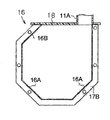
Fig. 1 is that expression is according to the main pipeline of the combing machine of the embodiment of the present invention and the schematic sectional view of suction channel;
The imperfect stereogram of the main pipeline of the combing machine that Fig. 2 A is presentation graphs 1 and suction channel;
The imperfect cutaway view of the location of the top cover of the main pipeline that Fig. 2 B is presentation graphs 2A;
Fig. 3 A means the cutaway view of the main pipeline of combing machine in accordance with another embodiment of the present invention;
Fig. 3 B is for meaning the cutaway view of the main pipeline of the combing machine of another embodiment according to the present invention; And
Fig. 4 is the schematic isometric of the noil collector unit of expression background technology.
The specific embodiment
The combing machine according to the embodiment of the present invention is described with reference to Fig. 1, Fig. 2 A and Fig. 2 B in below.Combing machine has a plurality of combing heads (for example 8 combing heads) and collects a plurality of suction channels 11 of the noil produced from each combing head.Combing machine also has and is set to the main pipeline 16 that suction channel 11 shares and is communicated with suction channel 11.
With reference to schematic sectional view, meaning the main pipeline 16 of combing machine and Fig. 1 of a suction channel 11, suction channel 11 has combing cylinder 12 and the brush below combing cylinder 12 13 of the position adjacent at the opening with suction channel 11 therein.Supply with roller 14 and be positioned at suction channel 11 tops, with the lap L that will be kept by the nipper (not shown), be supplied to combing cylinder 12.Combing cylinder 12 can be along the rotation of the counter clockwise direction in Fig. 1 with combing lap L.The staple fibre that brush 13 will be attached on the pin (not shown) of combing cylinder 12 is removed.The two pairs of detaching rollers 15 are positioned at supplies with roller 14 the place aheads, and rear pair of separated roller 15 is adjacent to configuration with the opening of suction channel 11, for pull the web F after combing and the web F after combing is placed on before the web that pulls.
As shown in Figure 2 A, main pipeline 16 is positioned at suction channel 11 belows, so that the direction of arranging along suction channel 11 is extended.As shown in Figure 1, each suction channel 11 has connecting portion 11A, and suction channel 11 is communicated with main pipeline 16 by connecting portion 11A, thereby allows the noil in suction channel 11 to be sent to main pipeline 16.The connecting portion 11A of suction channel 11 is positioned at through and comprises the side of imaginary perpendicular of the axis of main pipeline 16.Main pipeline 16 has two surperficial 16A with respect to the perpendicular inclination in the both sides of above-mentioned perpendicular in its underpart.In the present embodiment, each inclined plane 16A is provided by tabular surface.Main pipeline 16 is connected to the noil collector unit (not shown) as suction source at the one end.
Below will be described main pipeline 16 in detail.Shown in A and Fig. 2 B, main pipeline 16 comprises pipe main body 17 and top cover 18 as shown in Figure 1, Figure 2.Pipe main body 17 has 5 inner surfaces, two relative vertical planes, bottom surfaces and be formed on bottom surface and each vertical plane between aforementioned inclined plane 16A.Top cover 18 is configured to cover the upper opening of pipe main body 17.More specifically, pipe main body 17 forms by the shape that metallic plate is bent into to the pipeline with upper opening, so that have a pair of upper flange 17A extended along the longitudinal direction of pipe main body 17 in the upper end of pipe main body 17.Pipe main body 17 has the pair of end portions flange 17B of two longitudinal ends that are welded to pipe main body 17, for connecting the end wall (not shown) of main pipeline 16, or is connected to the noil collector unit for the end by main pipeline 16.Each end flange 17B has a plurality of hole 17C, and the bolt (not shown) inserts by hole 17C, for connecting end flange 17B, or for an end flange 17B is connected with the noil collector unit.If main pipeline 16 comprises a plurality of pipe main bodies 17 that link together, with end flange 17B, connect any two adjacent pipe main bodies 17.
The operation of combing machine as above will be described in below.In the operating period of combing machine, the lap L that utilizes combing cylinder 12 combings to be kept by nipper, thus remove the noil be included in lap L, such as the fiber inferior such as staple fibre with such as impurity such as worm are dirty.Carry out suction in the main pipeline 16 be connected to as the noil collector unit of suction source, and generation is aspirated in the suction channel 11 is communicated with main pipeline 16 by connecting portion 11A.By making to brush 13 rotations, will be attached to by combing lap L the staple fibre of the pin of combing cylinder 12, from combing cylinder 12, remove.The staple fibre then suction force in acting on suction channel 11 and main pipeline 16 is collected in the noil collector unit.
In the structure be communicated with main pipeline 16 via connecting portion 11A at suction channel 11, wherein connecting portion 11A is positioned at the side through the aforementioned perpendicular of the axis of main pipeline 16, and the air that makes to be extracted in main pipeline 16 turns round and round or flows in the eddy current mode in main pipeline 16.Unlike the main pipeline with rectangular section 31 of background technology, the main pipeline 16 of the present embodiment has the inclined plane 16A of the both sides that are formed on aforementioned perpendicular in its underpart.Therefore, make the air flow to main pipeline 16 from suction channel 11 by connecting portion 11A flow swimmingly in main pipeline 16, and can at the opposite side of perpendicular, not be stuck in the bottom of main pipeline 16, this helps prevent noil in the opposite side of perpendicular is deposited in the bottom of main pipeline 16.Unlike air mobile in the pipeline of rectangular section, the air in main pipeline 16 flows swimmingly with the less reduction of speed, and this contributes to improve web quality.
The suction air flow acted in the suction channel 11 on the rearward end of the web pulled before detaching roller 15 maintenances should preferably keep not fluctuation.At main pipeline, have as in the situation that the rectangular section of describing in background technology, noil often is deposited in the Zhong bight, bottom of main pipeline with speed faster, and the noil of therefore piling up like this need to be removed with the shorter time interval, so that the suction effect in suction channel is maintained to the level of expectation.Namely, need to be with the cleaning in shorter time interval chief executive road.Yet, in the combing machine of the present embodiment, wherein noil is difficult in the opposite side of perpendicular is deposited in the bottom of main pipeline 16, main pipeline 16 need not frequently clean.
The above embodiment of the present invention has following advantageous effects.
(1) combing machine comprises a plurality of combing heads and a plurality of suction channel 11, and suction channel 11 is collected in the noil that each combing head place produces due to grooming movement.Suction channel 11 has connecting portion 11A, and suction channel 11 is communicated with main pipeline 16 by connecting portion 11A.The connecting portion 11A of suction channel 11 is positioned at the side through the imaginary perpendicular of the axis of main pipeline 16.Main pipeline 16 has inclined plane 16A in its underpart in the both sides of perpendicular.Therefore, flow to air main pipeline 16 by connecting portion 11A from suction channel 11 and turning round and round in main pipeline 16 and flow swimmingly, and can not be stuck at the opposite side of perpendicular in the bottom of main pipeline 16, this has prevented that noil is deposited in main pipeline 16.
(2) smooth inclined plane 16A makes main pipeline 16 more easily to manufacture than arc surface.
(3) have a main pipeline 16 of transparent cap 18 more favourable than the background technology main pipeline 31 with observation window 35, because transparent area is larger, this provides better visual to the inside of main pipeline 16 for the operator.Permission helps the operator to observe the inside of main pipeline 16 from the transparent cap 18 of the inside of the bright main pipeline 16 of outside illumination in the operating period of combing machine.In addition, the use of transparent cap 18 makes main pipeline 16 in the background technology combing machine, and do not have noil to be deposited in stage portion or be deposited in observation window and main pipeline between gap in.
(4) be bonded under the state in groove 18A that the top cover 18 be placed on pipe main body 17 easily is installed on pipe main body 17 and remove from pipe main body 17 at upper flange 17A, this is conducive to the maintenance of the combing machine of needs removal top cover 18.
Describe in the case of the above embodiments the present invention, but the invention is not restricted to described embodiment.Obviously those skilled in the art can implement with the variety of way of following example.
Inclined plane 16A is not limited to tabular surface, but can be provided by arc surface.With the main pipeline with smooth inclined plane, compare, the main pipeline 16 with arc surface allows air to turn round and round more swimmingly in main pipeline 16.Arc surface is not limited to the arc surface constant by radius of curvature and forms, but a plurality of arc surfaces that can be different by radius of curvature form.
As shown in Figure 3A, the connecting portion 11A that can be arranged as each suction channel 11 is positioned at the side through the imaginary plane of the axis of main pipeline 16, and forms additional tilt face 16B at the opposite side of the perpendicular on the top that is arranged in main pipeline 16.As shown in Figure 3A, in the top of main pipeline 16 the opposite side of perpendicular arrange that additional tilt face 16B allows air in the situation that in main pipeline 16 than turning round and round more swimmingly at Fig. 1, so that noil more is difficult for being deposited in the bottom and top of main pipeline 16.
As shown in Figure 3 B, the bottom of main pipeline 16 can have semicircular surface.With the main pipeline 16 that has as shown in Figure 1 inclined plane 16A in its underpart, compare, this semicircular surface of main pipeline 16 allows air to turn round and round more swimmingly in main pipeline 16.
The transparent cap 18 that replaces main pipeline 16, the part of at least one side of Zhong inclined plane, the bottom 16A top that is positioned at main pipeline 16 of main pipeline 16 can be made by transparent material.In the main pipeline 16 of Fig. 3 A, inclined plane 16B and top cover 18 can form integral body.
Transparent material is not limited to acrylic resin, and can be any other resin or pottery.
Replace transparent material, top cover 18 can be made by opaque material.
Although top cover 18 is placed on pipe main body 17, top cover 18 can removably be arranged on pipe main body 17 by bolt.Alternatively, top cover 18 can be arranged on pipe main body 17 to allow the mode of opening top cover 18.
Claims (8)
1. a combing machine comprises:
A plurality of combing heads, combing lap (L) is to remove noil from each lap (L);
Main pipeline (16), be positioned at described combing head below; And
A plurality of suction channels (11), be positioned on described main pipeline (16) and there is connecting portion (11A), described suction channel (11) is communicated with described main pipeline (16) by this connecting portion (11A), thereby allow noil to be sent to described main pipeline (16) from described suction channel (11), described connecting portion (11A) is positioned at the side through the imaginary perpendicular of the axis of described main pipeline (16)
It is characterized in that, described main pipeline (16) has inclined plane (16A) in the both sides of described perpendicular in its underpart.
2. combing machine according to claim 1, is characterized in that, described inclined plane (16A) is tabular surface.
3. combing machine according to claim 1, is characterized in that, described inclined plane (16A) is arc surface.
4. according to the described combing machine of claims 1 to 3 any one, it is characterized in that, described main pipeline (16) has inclined plane (16B) at the opposite side of described perpendicular at an upper portion thereof.
5. combing machine according to claim 1, is characterized in that, described main pipeline (16) forms drum.
6. according to the described combing machine of claims 1 to 3 any one, it is characterized in that, described main pipeline (16) comprises the top cover (18) of the pipe main body (17) that the shape by metallic plate being bent into to the pipeline with upper opening forms and the upper opening that covers described pipe main body (17).
7. combing machine according to claim 6, it is characterized in that, described pipe main body (17) has the upper flange (17A) of extending along the longitudinal direction of described pipe main body (17) in the top, and described top cover (18) has the groove (18A) for receiving described upper flange (17A) in its lower surface.
8. according to the described combing machine of claims 1 to 3 any one, it is characterized in that, the part of at least one side of the top, described inclined plane (16A, 16B) of the top cover (18) of described main pipeline (16) or the bottom that is arranged in described main pipeline (16) of described main pipeline (16) is made by transparent material.
Applications Claiming Priority (2)
| Application Number | Priority Date | Filing Date | Title |
|---|---|---|---|
| JP2012-130031 | 2012-06-07 | ||
| JP2012130031A JP2013253346A (en) | 2012-06-07 | 2012-06-07 | Comber |
Publications (1)
| Publication Number | Publication Date |
|---|---|
| CN103484981A true CN103484981A (en) | 2014-01-01 |
Family
ID=48537819
Family Applications (1)
| Application Number | Title | Priority Date | Filing Date |
|---|---|---|---|
| CN201310222869.6A Pending CN103484981A (en) | 2012-06-07 | 2013-06-06 | Combing machine |
Country Status (3)
| Country | Link |
|---|---|
| EP (1) | EP2671978A1 (en) |
| JP (1) | JP2013253346A (en) |
| CN (1) | CN103484981A (en) |
Cited By (2)
| Publication number | Priority date | Publication date | Assignee | Title |
|---|---|---|---|---|
| CN106120031B (en) * | 2016-08-31 | 2018-07-06 | 浙江高和羊毛科技有限公司 | Inhale suede system in a kind of combing machine automatic control interval |
| CN108784936A (en) * | 2018-06-14 | 2018-11-13 | 张欢 | Bamboo fiber knitting object plane layer and its processing technology and sanitary napkin |
Families Citing this family (3)
| Publication number | Priority date | Publication date | Assignee | Title |
|---|---|---|---|---|
| CH710260A2 (en) * | 2014-10-16 | 2016-04-29 | Rieter Ag Maschf | Comber. |
| DE102017113089A1 (en) * | 2017-06-14 | 2018-12-20 | Trützschler GmbH & Co Kommanditgesellschaft | comber |
| CH719552A1 (en) * | 2022-03-28 | 2023-10-13 | Rieter Ag Maschf | Combing machine with a suction. |
Citations (8)
| Publication number | Priority date | Publication date | Assignee | Title |
|---|---|---|---|---|
| US905233A (en) * | 1907-06-01 | 1908-12-01 | Martin Roth | Combing-machine. |
| JPS50111419U (en) * | 1974-02-07 | 1975-09-11 | ||
| JPS6097779U (en) * | 1983-12-08 | 1985-07-03 | 株式会社豊田自動織機製作所 | spinning machine news duct |
| US5287597A (en) * | 1991-05-22 | 1994-02-22 | Reiter Machine Works, Ltd. | Apparatus for collecting lap pieces from a combing machine |
| CN1152638A (en) * | 1995-07-26 | 1997-06-25 | 里特机械公司 | Combing machine |
| JPH11107060A (en) * | 1997-10-03 | 1999-04-20 | Hara Shokki Seisakusho:Kk | Suction air flow controller for grouping suction apparatus in comber unit |
| CN101215739A (en) * | 2007-12-31 | 2008-07-09 | 经纬纺织机械股份有限公司 | Combing machine noil sucking air channel |
| CN101676453A (en) * | 2008-09-19 | 2010-03-24 | 村田机械株式会社 | Duct for textile machine and textile machine equipped with the same |
Family Cites Families (4)
| Publication number | Priority date | Publication date | Assignee | Title |
|---|---|---|---|---|
| JPS4124336Y1 (en) * | 1964-10-09 | 1966-12-12 | ||
| JPS4910328Y1 (en) * | 1968-05-17 | 1974-03-12 | ||
| DE3928280C2 (en) * | 1989-08-26 | 2001-03-22 | Truetzschler Gmbh & Co Kg | Device for feeding flake fiber material, for. B. cotton, man-made fibers and. Like., to a card or card |
| JPH0612483U (en) * | 1992-07-20 | 1994-02-18 | 株式会社原織機製作所 | Detection device for cotton drop in suction box of comber machine |
-
2012
- 2012-06-07 JP JP2012130031A patent/JP2013253346A/en active Pending
-
2013
- 2013-05-29 EP EP13169624.7A patent/EP2671978A1/en not_active Withdrawn
- 2013-06-06 CN CN201310222869.6A patent/CN103484981A/en active Pending
Patent Citations (8)
| Publication number | Priority date | Publication date | Assignee | Title |
|---|---|---|---|---|
| US905233A (en) * | 1907-06-01 | 1908-12-01 | Martin Roth | Combing-machine. |
| JPS50111419U (en) * | 1974-02-07 | 1975-09-11 | ||
| JPS6097779U (en) * | 1983-12-08 | 1985-07-03 | 株式会社豊田自動織機製作所 | spinning machine news duct |
| US5287597A (en) * | 1991-05-22 | 1994-02-22 | Reiter Machine Works, Ltd. | Apparatus for collecting lap pieces from a combing machine |
| CN1152638A (en) * | 1995-07-26 | 1997-06-25 | 里特机械公司 | Combing machine |
| JPH11107060A (en) * | 1997-10-03 | 1999-04-20 | Hara Shokki Seisakusho:Kk | Suction air flow controller for grouping suction apparatus in comber unit |
| CN101215739A (en) * | 2007-12-31 | 2008-07-09 | 经纬纺织机械股份有限公司 | Combing machine noil sucking air channel |
| CN101676453A (en) * | 2008-09-19 | 2010-03-24 | 村田机械株式会社 | Duct for textile machine and textile machine equipped with the same |
Cited By (2)
| Publication number | Priority date | Publication date | Assignee | Title |
|---|---|---|---|---|
| CN106120031B (en) * | 2016-08-31 | 2018-07-06 | 浙江高和羊毛科技有限公司 | Inhale suede system in a kind of combing machine automatic control interval |
| CN108784936A (en) * | 2018-06-14 | 2018-11-13 | 张欢 | Bamboo fiber knitting object plane layer and its processing technology and sanitary napkin |
Also Published As
| Publication number | Publication date |
|---|---|
| EP2671978A1 (en) | 2013-12-11 |
| JP2013253346A (en) | 2013-12-19 |
Similar Documents
| Publication | Publication Date | Title |
|---|---|---|
| CN103484981A (en) | Combing machine | |
| US9695526B2 (en) | Support element for a compacting device for a drawing system in a spinning machine | |
| CN105431580B (en) | The cleaning device of combing cylinder for combing machine | |
| CN106574408B (en) | For cleaning the device of the roller surface of drafting system | |
| CN103562450B (en) | Induction element in the nipper units of comber | |
| CN106795657B (en) | Suction unit for combing machine | |
| CN105780207A (en) | Cleaning mechanism of carding machine | |
| CN102776618B (en) | Spinning device for air exhaust type rotor spinning machine | |
| CN202146821U (en) | Movable electrode type electrostatic precipitator | |
| ITMI961553A1 (en) | FIBER COMBING MACHINE | |
| CN217222546U (en) | Fine hair weaving is with brushing hair device | |
| CN103147137A (en) | Unginned cotton clearing machine | |
| JP6075988B2 (en) | Focusing device for spinning machines | |
| CN102471948B (en) | Apparatus for forming a sliver | |
| ITMI980287A1 (en) | DEVICE AND PROCEDURE FOR CLEANING THE GASKETS OF MOVABLE HATS IN A HAT CARD | |
| CN102089468A (en) | Working element on a fibre-processing machine | |
| CN102443888B (en) | Pressure rod and spinning preparation machine with the pressure rod | |
| CN101812748B (en) | Reinforced insert part of suction passageway for fiber bundling device | |
| CN209010654U (en) | A kind of opener with Anti-blockage function | |
| CN211005757U (en) | Heel and toe end head removable cover plate | |
| ITMI972054A1 (en) | TEXTILE MACHINE WITH AN IRONING MACHINE FOR FIBROUS MATERIAL | |
| CN1327055C (en) | Apparatus for cleaning moving blind flange guiding device in blind flange carding machine | |
| CN1269714C (en) | Rotary disc for storing strip device for draw frame and combing machine | |
| CN205329235U (en) | Open miscellaneous mechanism of row of dust removal | |
| CN217203084U (en) | Novel carding structure |
Legal Events
| Date | Code | Title | Description |
|---|---|---|---|
| C06 | Publication | ||
| PB01 | Publication | ||
| C10 | Entry into substantive examination | ||
| SE01 | Entry into force of request for substantive examination | ||
| RJ01 | Rejection of invention patent application after publication |
Application publication date: 20140101 |
|
| RJ01 | Rejection of invention patent application after publication |