CN103291365A - Fluid machine and engine with rotating wheel vortex mechanism - Google Patents
Fluid machine and engine with rotating wheel vortex mechanism Download PDFInfo
- Publication number
- CN103291365A CN103291365A CN2013101989810A CN201310198981A CN103291365A CN 103291365 A CN103291365 A CN 103291365A CN 2013101989810 A CN2013101989810 A CN 2013101989810A CN 201310198981 A CN201310198981 A CN 201310198981A CN 103291365 A CN103291365 A CN 103291365A
- Authority
- CN
- China
- Prior art keywords
- runner
- chamber
- vortex
- piston
- cylinder sleeve
- Prior art date
- Legal status (The legal status is an assumption and is not a legal conclusion. Google has not performed a legal analysis and makes no representation as to the accuracy of the status listed.)
- Pending
Links
Images


Classifications
-
- Y—GENERAL TAGGING OF NEW TECHNOLOGICAL DEVELOPMENTS; GENERAL TAGGING OF CROSS-SECTIONAL TECHNOLOGIES SPANNING OVER SEVERAL SECTIONS OF THE IPC; TECHNICAL SUBJECTS COVERED BY FORMER USPC CROSS-REFERENCE ART COLLECTIONS [XRACs] AND DIGESTS
- Y02—TECHNOLOGIES OR APPLICATIONS FOR MITIGATION OR ADAPTATION AGAINST CLIMATE CHANGE
- Y02T—CLIMATE CHANGE MITIGATION TECHNOLOGIES RELATED TO TRANSPORTATION
- Y02T10/00—Road transport of goods or passengers
- Y02T10/10—Internal combustion engine [ICE] based vehicles
- Y02T10/12—Improving ICE efficiencies
Abstract
The invention discloses a rotary displacement type rotating wheel vortex mechanism (1) for a fluid machine and an engine. The rotating wheel vortex mechanism (1) is divided into an inner rotating wheel vortex mechanism (2) and an outer rotating wheel vortex mechanism (3) according to structural characteristics, wherein concave wheel rotors (6) of the inner rotating wheel vortex mechanism (2) are meshed for dynamic sealing rotation in an inner rotating wheel cylinder sleeve (4); convex wheel pistons (8) are arranged on the concave wheel rotors (6); the convex wheel pistons (8) and the concave wheel rotors (6) rotate together and automatically rotate in the same direction; fluid in a vortex chamber (16) between the two convex wheel pistons (8) is continuously sucked and discharged under the action of a separator (15); convex wheel rotors (37) of the outer rotating wheel vortex mechanism (3) are meshed for dynamic sealing rotation in an outer rotating wheel cylinder sleeve (36); concave wheel pistons (38) are fixed on the outer rotating wheel cylinder sleeve (36) and are meshed with the convex wheel rotors (37) for dynamic sealing reverse rotation; the fluid in the vortex chamber (16) between two convex wheels (47) on the convex wheel rotors (37) is continuously sucked and discharged under the action of the concave wheel pistons (38).
Description
Technical field
The present invention is a kind of runner of the rotary displacement for fluid machinery and motor vortex mechanism, relate to the technical field of the fluid machineries such as ventilator, pump, hydraulic activator, pneumatic motor, compressor, thermal expansion dynamic power machine, and relate to technical field of engines.
Background technique
The fluid machinery used at present is divided into volume fluid machine and impeller driving type fluid machinery, impeller driving type fluid machinery working method is that impeller carries out work at an open working cavity high speed motion convection cell, simple in structure but a lot of defects such as have that noise is large, efficiency is low, volume fluid machine efficiency is relatively high, but the complex structure swept volume is limited, can not meet large volumes of fluid requirements of one's work; Be badly in need of a kind of simple structure but stable efficiency, rotary displacement mechanism that high power capacity is large, change the properties that existing fluid machinery and motor can't further improve because of the structural imperfection restriction.
Summary of the invention
The runner vortex mechanism that the purpose of this invention is to provide a kind of rotary displacement, operation mechanism as fluid machinery and motor, be used for improving the properties of ventilator, pump, hydraulic activator, water turbine, pneumatic motor, compressor, steam turbine and the gas turbine of fluid machinery technical field, and the properties that is used for improving motor.
For achieving the above object, the technical measures of taking are: the runner vortex mechanism forms by interior runner vortex mechanism or by outer runner vortex mechanism; Interior runner vortex mechanism is comprised of interior runner cylinder sleeve, transmission shaft, the recessed rotor, cam piston, interior bent axle, quiet gear and the moving gear of taking turns of taking turns; The left and right end face of interior runner cylinder sleeve is fixed with the bearing seal seat, and the one or both ends of transmission shaft are fixed with bearing seal, and bearing seal is arranged in the bearing seal seat; Transmission shaft is concentric fixing with the recessed rotor of taking turns, recessedly take turns the inside that rotor is arranged on interior runner cylinder sleeve with one heart, this recessed wheel between rotor and interior runner cylinder sleeve cylinder body wall has a cylinder sleeve chamber, this recessed side end face of taking turns rotor is fixed with a slice or two runner dishes, the cylinder body wall rotary dynamic seal of runner dish and interior runner cylinder sleeve; There is one or more divider the inside of cylinder sleeve chamber, in the outer wall of divider, between the ring wall surface of top and web, meshes rotary dynamic seal.Inside take turns on the axostylus axostyle of bent axle and be fixed with cam piston, inside take turns bent axle and cam piston Concentric rotation; Have more than one arc groove on recessed web ring wall surface of taking turns rotor, cam piston is arranged on the inside of arc groove with one heart, and cam piston is dynamic-sealing rotary in arc groove; Recessed runner dish side of taking turns rotor is fixed with sealed bearing, and inside taking turns bent axle external stability has the stuffing box bearing part, and the stuffing box bearing part is arranged in sealed bearing, and the axle head of inside taking turns bent axle is fixed with moving gear and piston counterbalance; Quiet gear is fixed on the inboard wall of cylinder block face of interior runner cylinder sleeve, and moving gear and quiet gear are intermeshing; A gear chamber is arranged between the inboard wall of cylinder block face of interior runner cylinder sleeve and runner dish, moving gear rotates in gear chamber around quiet gear and rotation, lubricant oil is arranged in gear chamber, and moving gear is taken turns that bent axle drives cam piston in arc groove and rotatablely moves cylinder sleeve is indoor by interior.The piston wheel of cam piston meshes rotary dynamic seal with the internal face of cylinder sleeve chamber, the cam body of cam piston and divider engagement rotary dynamic seal; The arc length of the sealing wall of divider is taken turns with the distribution angle number of degrees in the cam piston center of circle and the ratio of the cam body distribution angle number of degrees than equaling piston with the indoor wall arc length of cylinder sleeve; Cam piston and the recessed rotor of taking turns rotate simultaneously, the rotation of cam piston equidirectional; The number of cylinder sleeve indoor separation part and the recessed proportional relation of rotating cycle of taking turns rotor, cylinder sleeve is indoor have N divider, the diameter of quiet gear be the moving gear diameter N doubly, recessed rotor one circle of taking turns, cam piston rotation N circle; Cam piston and divider engagement dynamic-sealing rotary, cam piston is in rotary moving by relatively-stationary divider; Have the fluid suction passage near the rear separation of divider sealing wall, near the front separation of divider sealing wall, have the discharge runner, divider is separated into not connected suction chamber and discharge chamber by the vortex chamber between two cam pistons.Outer runner vortex mechanism is comprised of outer runner cylinder sleeve, transmission shaft, cam follower, recessed piston, piston sleeve, foreign steamer bent axle, master gear and the pinion of taking turns; Be fixed with the bearing seal seat on the left and right end face of outer runner cylinder sleeve, the one or both ends of transmission shaft are fixed with bearing seal, and bearing seal is arranged in the bearing seal seat; Transmission shaft is concentric fixing with cam follower, this cam follower is arranged in the cylinder sleeve chamber of outer runner cylinder sleeve inside with one heart, be fixed with more than one cam on the change outer wall of this cam follower web, the middle Surface of action of cam circular arc wall and the ring wall surface of outer runner cylinder sleeve engagement rotary dynamic seal; Be fixed with the recessed piston of taking turns on the axostylus axostyle of foreign steamer bent axle, this foreign steamer bent axle and the recessed piston Concentric rotation of taking turns; Foreign steamer turns on the outer wall of cylinder sleeve and is fixed with one or more piston sleeve, the inside of piston sleeve is connected by the piston notch with the inside of outer runner cylinder sleeve, recessedly take turns the inside that piston is arranged on piston sleeve with one heart, the recessed piston dynamic-sealing rotary in piston sleeve of taking turns, it is indoor that recessed in piston sleeve taken turns the cylinder sleeve that piston enters outer runner cylinder sleeve inside by the piston notch; The upper shield sealed bearing that the two ends of piston sleeve are fixed with, the external stability of foreign steamer bent axle has the stuffing box bearing part, the stuffing box bearing part is arranged in the upper shield sealed bearing, the axle head of foreign steamer bent axle is fixed with pinion and piston counterbalance, there is a gear chamber inside, side of outer runner cylinder sleeve, lubricant oil is arranged in gear chamber, master gear in this gear chamber is fixed on transmission shaft, transmission shaft drives cam follower and master gear rotates simultaneously, master gear drives the pinion rotation, and pinion drives and recessedly takes turns piston in piston sleeve and rotatablely move cylinder sleeve is indoor by the foreign steamer bent axle.Rotary dynamic seal between the change outer wall of recessed piston wheel of taking turns piston and cam follower, rotary dynamic seal between the circular arc wall of recessed sealing wall of taking turns the recessed wheel body of piston and cam follower cam; The arc length ratio of the arc length of fixed wall and cam follower outer wall between the front end of cam follower cam and rear end, equal the ratio of the center of circle distribution angle number of degrees of the recessed center of circle distribution angle number of degrees of taking turns piston fovea superior wheel body and piston wheel; The distributed quantity of cam follower overhead cam determines rotating speed and the recessed rotating ratio of taking turns piston of cam follower, and N cam arranged on cam follower, and the diameter of master gear is N times of pinion, and cam follower revolves and turns around, the recessed piston rotation N circle of taking turns; Have the suction passage communicated with the cylinder sleeve chamber interior near the front immovable point of the outer wall of outer runner cylinder sleeve and piston sleeve, near the rear immovable point of the outer wall of outer runner cylinder sleeve and piston sleeve, have the discharge runner communicated with the cylinder sleeve chamber interior; The recessed piston of taking turns, in the fixing rotation of cylinder sleeve chamber interior, is divided into suction chamber and discharge chamber by two recessed vortex chambers of taking turns between piston.The recessed wheel between rotor and transmission shaft of interior runner vortex mechanism has an impeller plate, there is the above blade of a slice the inside of this impeller plate, the dish cover of this impeller plate is fixed on the outside of transmission shaft, have annular entrance near the dish cover of this impeller plate, between two adjacent blades of this impeller plate, a vortex cavity is arranged, the import of this vortex cavity communicates with annular entrance, and the vortex mouth of this vortex cavity is opened near recessed pit joint of taking turns rotor.An impeller plate is arranged between the cam follower of outer runner vortex mechanism and transmission shaft, there is the above blade of a slice the inside of this impeller plate, the dish cover of this impeller plate is fixed on the outside of transmission shaft, have annular entrance near the dish cover of this impeller plate, between two adjacent blades of this impeller plate, a vortex cavity is arranged, the import of this vortex cavity communicates with annular entrance, and the vortex mouth of this vortex cavity is opened near the rear end of cam follower cam.In the runner vortex mechanism, more than one interior runner vortex mechanism interconnects work in combination by transmission shaft and forms runner vortex mechanism in a combination, a plurality of recessed rotor of taking turns in this combination in the runner vortex mechanism interfixes, a plurality of cam pistons are fixing by wheel bent axle series connection in, inside take turns bent axle and drive a plurality of cam pistons by moving gear and a quiet meshed transmission gear and move simultaneously; In the runner vortex mechanism, more than one outer runner vortex mechanism interconnects work in combination by transmission shaft, form the outer runner vortex mechanism of a combination, between adjacent piston sleeve in the outer runner vortex mechanism of this combination, interfix, a plurality of recessed pistons of taking turns are fixing by a foreign steamer bent axle series connection, and the foreign steamer bent axle drives a plurality of recessed pistons of taking turns by pinion and a master gear engagement driving and moves simultaneously.The runner vortex mechanism is pressed the operating characteristic of fluid machinery and motor inner fluid, is divided into gas transportation machine structure, liquid transporting body, hydraulic drive mechanism, air pressure driving mechanism, gas compression mechanism, thermal expansion acting mechanism and combustion power mechanism.
As the present invention, further improve, the runner vortex mechanism is as the gas transportation machine structure, and the technical measures of taking are: the suction tude of runner ventilator is connected with the suction passage of runner vortex mechanism; Suction tude with the runner ventilator of the impeller plate is connected with the annular entrance of the impeller plate; The outlet pipe of runner ventilator is connected with the discharge runner of runner vortex mechanism; Change the sense of rotation of transmission shaft, runner ventilator commutation work.
As the present invention, further improve, the runner vortex mechanism is as liquid transporting body, the technical measures of taking are: the liquid inlet pipe of liquor pump is connected with the suction passage of runner vortex mechanism, with the liquid inlet pipe of impeller plate liquor pump, with the annular entrance of the runner vortex mechanism impeller plate, is connected; The liquid-discharging tube of liquor pump is connected with the discharge runner of runner vortex mechanism; Change the sense of rotation of transmission shaft, liquor pump commutation work.
As the present invention, further improve, the runner vortex mechanism is as hydraulic drive mechanism, the technical measures of taking are: the hydrokinetic machine with hydraulic drive mechanism, pressured fluid enters the suction chamber inside of vortex chamber from liquid inlet pipe, the suction chamber volume increases, the volume of discharge chamber synchronously reduces, and transmission shaft rotates outputting power work; The working medium of rotary-type water turbine is press water, the work of transmission shaft rotation outputting power.
Advance an improvement as the present invention, the runner vortex mechanism is as the air pressure driving mechanism, the technical measures of taking are: the working medium with pneumatic motor of air pressure driving mechanism is pressed gas, the suction chamber that pressed gas enters, the work of transmission shaft rotation outputting power.
As the present invention, further improve, the runner vortex mechanism is as gas compression mechanism, and the technical measures of taking are: have the runner compressor of gas compression mechanism, the discharge runner of runner vortex mechanism is in-built safety check; Outlet pipe is in the lubricating chamber inside of oil lubrication cooling unit, this lubricating chamber is fixed on the outside of interior runner cylinder sleeve or outer runner cylinder sleeve, lubricant oil is arranged in lubricating chamber, lubricant oil enters circulating cooling in cooler by the oil pipe of the cooler that is connected with lubricating chamber, and the spray bar of cooler is communicated with the oilhole of interior runner cylinder sleeve or outer runner cylinder sleeve; The runner compressor utilizes the single runner vortex mechanism to carry out multistage compression work, the swept volume of higher level's vortex chamber of interior runner vortex mechanism or outer runner vortex mechanism is greater than the swept volume of subordinate's vortex chamber, cooling storage in the middle of having between higher level's vortex chamber and subordinate's vortex chamber; The runner compressor utilizes the capable single-stage of a plurality of runner vortex mechanisms or multistage compression work, and the runner vortex mechanism of runner compressor forms by runner vortex mechanism in combination or by the outer runner vortex mechanism of combination.
As the present invention, further improve, the technical measures of taking are: the rotary-type steam turbine with thermal expansion acting mechanism is divided into the rotary-type steam turbine of single-stage and multistage rotary-type steam turbine; The air intake control valve of the rotary-type steam turbine of single-stage is opened, and steam enters in the suction chamber of the rotary-type steam turbine vortex chamber of single-stage from suction tude, and air intake control valve is closed, and steam expands and does work at suction chamber, and the steam after the acting of expanding is discharged by outlet pipe; The air intake control valve of multistage rotary-type steam turbine is opened, steam enters in the suction chamber of first order runner vortex mechanism vortex chamber from suction tude, air intake control valve is closed, steam expands and does work at suction chamber, the steam expanded after acting, by the suction tude of the second level runner vortex mechanism that is connected with outlet pipe, enters in the runner vortex mechanism of the second level and carries out the reexpansion acting; Steam in rotary-type steam turbine is discharged after the acting of repeatedly expanding.
As the present invention, further improve, the technical measures of taking are: have the rotary-type gas turbine of runner vortex mechanism, be comprised of gas compression mechanism, firing chamber, fuel feeding ignition trigger control system, external cooling device and thermal expansion acting mechanism; On rotary-type gas turbine, external cooling device is housed, this external cooling device is by air-cooled or water cooling work; Gas compression mechanism and thermal expansion acting mechanism are fixed on same transmission shaft, be fixed with firing chamber between gas compression mechanism and thermal expansion acting mechanism, the inside that the oil nozzle of fuel feeding ignition trigger control system and igniter are arranged on firing chamber, the outlet pipe of gas compression mechanism is communicated with the firing chamber import, and the fuel tube of firing chamber is connected with the air intake control valve of thermal expansion acting mechanism; Rotary-type gas turbine carries out interior cooling work, in thermal expansion acting mechanism, the impeller plate is arranged, the vortex mouth of this impeller plate is fixed with safety check, and the cooling tube of interior device for cooling is connected with the annular entrance of the impeller plate, air intake control valve is closed, and interior device for cooling carries out cooling work in air.
As the present invention, further improve, the technical measures of taking are: the combustion power mechanism with rotor engine of runner vortex mechanism is comprised of gas compression mechanism and thermal expansion acting mechanism, rotor engine is equipped with external cooling device, and this external cooling device is by air-cooled or water cooling work; Gas compression mechanism and thermal expansion acting mechanism are fixed on same transmission shaft, between gas compression mechanism and thermal expansion acting mechanism, gas reservoir is housed, the compression exhaust pipe is connected with the solar term control valve of gas reservoir, on the suction passage of thermal expansion acting mechanism, admission controller is housed, this admission controller is communicated with the cooled exhaust pipe of gas reservoir and the startup tracheae of solar term control valve respectively; The oil nozzle of fuel feeding ignition trigger system is installed in the suction passage of this thermal expansion acting mechanism, and spark plug is arranged near the inside oil nozzle of cylinder sleeve chamber; Rotor engine carries out interior cooling work, in thermal expansion acting mechanism, the impeller plate is arranged, the vortex mouth of this impeller plate is fixed with safety check, and the cooling tube of interior device for cooling is connected with the annular entrance of the impeller plate, admission controller is closed, and interior device for cooling carries out cooling work in air.
As the present invention, further improve, the technical measures of taking are: the jet power mechanism with air breathing engine of runner vortex mechanism is comprised of with the burning gas ejecting system gas compression mechanism, thermal expansion acting mechanism, gas compression mechanism and thermal expansion acting mechanism are fixed on same transmission shaft, the outlet pipe of gas compression mechanism is connected with the admission controller of thermal expansion acting mechanism, the outlet pipe of this gas compression mechanism also is connected with the jet control valve of burning gas ejecting system firing chamber, igniter and oil nozzle are arranged in firing chamber, the rear end of this firing chamber is connected with jet pipe, and the outlet pipe of thermal expansion acting mechanism is connected with the jet runner of jet pipe outside, air breathing engine carries out press work, the hollow portion of transmission shaft has the air inlet reservoir chamber, separate by more than one non-return suction valve this air inlet reservoir chamber, the one-level suction tude of gas compression mechanism is at the front end of the first non-return suction valve, the one-level outlet pipe of gas compression mechanism communicates with the first reservoir chamber of air inlet reservoir chamber, the secondary suction tude of gas compression mechanism communicates with the first reservoir chamber, the secondary outlet pipe communicates with the second reservoir chamber of the second safety check rear end, the final vacuum Guan Yuhou reservoir chamber of gas compression mechanism communicates, the suction tude that mechanism was done in thermal expansion communicates with rear reservoir chamber, the jet control valve of firing chamber is connected with rear reservoir chamber.
The accompanying drawing explanation
Below in conjunction with accompanying drawing, the present invention is described in further detail.
Fig. 1 is the schematic diagram of runner vortex mechanism in the present invention.
Fig. 2 is the sectional view of runner vortex mechanism in the present invention.
Fig. 3 is the schematic diagram of the outer runner vortex mechanism of the band impeller plate of the present invention.
Fig. 4 is the schematic diagram of the outer runner vortex mechanism of the present invention.
Fig. 5 is the schematic diagram of the interior runner vortex mechanism of the band impeller plate of the present invention.
Fig. 6 is the sectional view of the outer runner vortex mechanism of the present invention.
Fig. 7 is the schematic diagram of the rotary-type compressor of the present invention.
Fig. 8 is the schematic diagram of thermal expansion of the present invention acting mechanism.
Fig. 9 is the schematic diagram of athodyd of the present invention.
Figure 10 is the schematic diagram of air breathing engine of the present invention.
Figure 11 is the schematic diagram that the present invention combines interior runner mechanism.
Figure 12 is the sectional view of the rotary-type steam turbine of the present invention.
Figure 13 is the sectional view that the present invention combines outer runner mechanism.
Figure 14 is the sectional view of hydraulic drive mechanism of the present invention.
Figure 15 is the sectional view of hydraulic conveyor structure of the present invention.
Figure 16 is the sectional view of the rotary-type gas turbine of the present invention.
Figure 17 is the sectional view of rotor engine of the present invention.
Figure 18 is the schematic diagram of rotor engine of the present invention.
Figure 19 is the schematic diagram of wheel bent axle in the present invention.
Figure 20 is the schematic diagram of foreign steamer bent axle of the present invention.
Embodiment
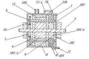
As shown in Fig. 1, Fig. 4, runner vortex mechanism 1 forms by interior runner vortex mechanism 2 or by outer runner vortex mechanism 3, as shown in Figure 1 and Figure 2, interior runner vortex mechanism 2 by interior runner cylinder sleeve 4, transmission shaft 5, recessedly take turns rotor 6, cam piston 8, interiorly take turns bent axle 9, quiet gear 7 forms with moving gear 10, the left and right end face of interior runner cylinder sleeve 4 is fixed with bearing seal seat 4-1, and as shown in Figure 15, Fig. 2, the one or both ends of transmission shaft 5 are fixed with bearing seal 11, and bearing seal 11 is arranged in bearing seal seat 4-1, transmission shaft 5 is concentric fixing with the recessed rotor 6 of taking turns, recessedly take turns the inside that rotor 6 is arranged on interior runner cylinder sleeve 4 with one heart, this recessed wheel between rotor 6 and interior runner cylinder sleeve 4 cylinder body wall 4-2 has a cylinder sleeve chamber 12, this recessed side end face 6-1 that takes turns rotor 6 is fixed with a slice or two runner dishes 13, runner dish 13 and interior runner cylinder sleeve 4 cylinder body wall 4-2 rotary dynamic seals, there is one or more divider 15 inside of cylinder sleeve chamber 12, in the outer wall of divider 15, between the ring wall surface 14-1 of top 15-1 and web 14, meshes rotary dynamic seal, as shown in figure 19, inside take turns on the axostylus axostyle 9-2 of bent axle 9 and be fixed with cam piston 8, inside take turns bent axle 9 and cam piston 8 Concentric rotations, have more than one arc groove 17 on the ring wall surface 14-1 of recessed web 14 of taking turns rotor 6, cam piston 8 is arranged on the inside of arc groove 17 with one heart, and cam piston 8 is at the interior dynamic-sealing rotary of arc groove 17, recessed side of taking turns the runner dish 13 of rotor 6 is fixed with sealed bearing 18, inside take turns bent axle 9 external stabilities stuffing box bearing part 19 is arranged, stuffing box bearing part 19 is arranged in sealed bearing 18, and in this, the axle head 9-1 of wheel bent axle 9 is fixed with moving gear 10 and piston counterbalance 10-1, quiet gear 7 is fixed on the inboard wall of cylinder block face 4-3 of interior runner cylinder sleeve 4, transmission shaft 5 rotates in the hollow portion 7-1 of quiet gear 7, moving gear 10 is intermeshing with quiet gear 7, a gear chamber 51 is arranged between the inboard wall of cylinder block face 4-3 of interior runner cylinder sleeve 4 and runner dish 13, moving gear 10 around quiet gear 7 in the interior rotation of gear chamber 51 rotation, lubricant oil 50 is arranged in gear chamber 51, and moving gear 10 reaches and rotatablely moves in cylinder sleeve chamber 12 in arc groove 17 by the interior bent axle 9 drive cam pistons 8 of taking turns, piston wheel 20 on cam piston 8 meshes rotary dynamic seal with the internal face 12-1 of cylinder sleeve chamber 12, the cam body 21 of cam piston 8 and divider 15 engagement rotary dynamic seals, the arc length of the sealing wall 25 of divider 15 and cylinder sleeve chamber 12 internal face 12-1 arc length than equal piston wheel 20 at the distribution angle 20-1 number of degrees with cam piston 8 centers of circle ratio with the distribution angle 21-1 number of degrees of cam body 21, cam piston 8 rotates also equidirectional rotation with the recessed rotor 6 of taking turns simultaneously, the piston wheel 20 of cam piston 8 is intermeshing with the front separation 23 of the front joint 22 of cam body 21 and divider 15, the forward intersection point 22 of cam piston 8 turns in divider 15 outer walls near the 15-1 of top, before being somebody's turn to do, joint 22 is simultaneously near the front groove joint 26 of arc groove 17, the rear joint 28 of cam piston 8 is from turning in arc groove 17 near the pit joint 26-1 of arc groove 17, and cam body 21 outer wall 24 are separated with the sealing wall 25 of divider 15, the piston of cam piston 8 is taken turns 20 outer wall 20-2 and cylinder sleeve chamber 12 internal face 12-1 gear motions, 15-1 rotary dynamic seal engagement in top in the outer wall of the recessed ring wall surface 14-1 that takes turns rotor 6 webs 14 and divider 15, the number of the interior divider 15 in cylinder sleeve chamber 12 and cam piston 8 and the recessed proportional relation of rotating cycle of taking turns rotor 6, N divider 15 arranged in cylinder sleeve chamber 12, the diameter of quiet gear 7 be moving gear diameter 10 N doubly, cam piston 8 rotation N circles, the recessed rotor 6 of taking turns revolves and turns around, cam piston 8 and divider 15 dynamic-sealing rotary engagements, cam piston 8 is in rotary moving by relatively-stationary divider 15, have fluid suction passage 30 near the rear separation 23-1 of divider 15 sealing walls 25, have fluid expulsion runner 32 near the front separation 23 of divider 15 sealing walls 25, the vortex chamber 16 of divider 15 between two cam pistons 8 is separated into not connected suction chamber 33 and discharge chamber 34, along with the relative movement of divider 15 in vortex chamber 16, fluid 35 enters in suction chamber 33 from suction passage 30, the volume of suction chamber 33 progressively increases by zero, fluid 35 in discharge chamber 34 is discharged from discharging runner 32 under the mutual squeezing action of divider 15 and cam piston 8 pistons wheels 20 simultaneously, when the volume of discharge chamber 34 progressively reduces to make zero, fluid 35 in discharge chamber 34 is all discharged.As shown in Fig. 4, Fig. 6, outer runner vortex mechanism 3 is comprised of outer runner cylinder sleeve 36, transmission shaft 5, cam follower 37, recessed piston 38, piston sleeve 39, foreign steamer bent axle 40, master gear 41 and the pinion 42 of taking turns, be fixed with bearing seal seat 36-1 on the left and right end face of outer runner cylinder sleeve 36, as shown in Figure 14, Fig. 6, the one or both ends of transmission shaft 5 are fixed with bearing seal 11, and bearing seal 11 is arranged in bearing seal seat 36-1, transmission shaft 5 is concentric fixing with cam follower 37, cam follower 37 is arranged in the cylinder sleeve chamber 12 of outer runner cylinder sleeve 36 inside with one heart, be fixed with one or more cam 47 on change 45 outer wall 46 of these cam follower 37 webs 44, ring wall surface 49 rotary dynamic seals of Surface of action 48-1 and outer runner cylinder sleeve 36 in the middle of the circular arc wall 48 of cam 47, as shown in figure 20, be fixed with the recessed piston 38 of taking turns on the axostylus axostyle 40-2 of foreign steamer bent axle 40, this foreign steamer bent axle 40 and recessed piston 38 Concentric rotations of taking turns, foreign steamer turns on the outer wall 36-1 of cylinder sleeve 36 and is fixed with one or more piston sleeve 39, the inside of piston sleeve 39 is connected by piston notch 39-1 with the inside of outer runner cylinder sleeve 36, recessedly take turns the inside that piston 38 is arranged on piston sleeve 39 with one heart, the recessed piston 38 of taking turns is at the interior dynamic-sealing rotary of piston sleeve 39, and the recessed piston 38 of taking turns in piston sleeve 39 enters in the cylinder sleeve chamber 12 of outer runner cylinder sleeve 36 inside by piston notch 39-1, the upper shield sealed bearing 39-2 that the two ends of piston sleeve 39 are fixed with, the external stability of foreign steamer bent axle 40 has stuffing box bearing part 19, stuffing box bearing part 19 is arranged in upper shield sealed bearing 39-2, and the axle head 40-1 of foreign steamer bent axle 40 is fixed with pinion 42 and piston counterbalance 42-1, there is a gear chamber 51 inside, side of outer runner cylinder sleeve 36, lubricant oil 50 is arranged in gear chamber 51, master gear 41 in this gear chamber 51 is fixed on transmission shaft 5, transmission shaft 5 drives cam follower 37 and rotates with master gear 41 simultaneously, master gear 41 drives pinion 42 rotations, and pinion 42 drives the recessed piston 38 of taking turns by foreign steamer bent axle 40 and reaches and rotatablely move in cylinder sleeve chamber 12 in piston sleeve 39, rotary dynamic seal between the outer wall 46 of recessed piston wheel 52 of taking turns piston 38 and cam follower 37 changes 45, rotary dynamic seal between the circular arc wall 48 of recessed sealing wall 56 of taking turns the recessed wheel body 53 of piston 38 and cam follower 37 cams 47, cam follower 37 oppositely meshes rotation with the recessed piston 38 of taking turns simultaneously, the front end 47-1 of cam 47 and recessed frontal arc end 57 of taking turns between piston 38 piston wheels 52 and recessed wheel body 53 are intermeshing, the rear end 47-2 of cam 47 and recessed backarc end 59 of taking turns between piston 38 pistons wheels 52 and recessed wheel body 53 are intermeshing, between the outer wall 46 of recessed piston wheel 52 of taking turns piston 38 and cam follower 37 changes 45, mesh rotary dynamic seal, as shown in Figure 5, the arc length ratio of the cam 47 front end 47-1 of cam follower 37 and the arc length of the fixed wall 45-1 between the 47-2 of rear end and cam follower 37 outer wall 46, equal the ratio of the center of circle distribution angle 52-1 number of degrees of the recessed center of circle distribution angle 53-1 number of degrees of taking turns piston 38 fovea superior wheel bodys 53 and piston wheel 52, the distributed quantity of cam follower 37 overhead cams 47 determines cam follower 37 rotating speeds and recessed ratio of taking turns piston 38 rotating speeds, and N cam 47 arranged on cam follower 37, and cam follower 37 revolves and turns around, the recessed piston 38 rotation N circles of taking turns, and the diameter of master gear 41 is N times of pinion 42, near the outer wall 60 of outer runner cylinder sleeve 36 and the front immovable point 61 of piston sleeve 39, have and the suction passage 30 communicated in cylinder sleeve chamber 12, near the outer wall 60 of outer runner cylinder sleeve 36 and the rear immovable point 62 of piston sleeve 39, having communicates with 12 inside, cylinder sleeve chamber discharges runner 32, the recessed piston 38 of taking turns, at cylinder sleeve chamber 12 internal rotatings, is divided into suction chamber 33 and discharge chamber 34 by two recessed vortex chambers 16 of taking turns between piston 38, cam follower 37 rotations, suction chamber 33 volumes progressively increase by zero, fluid 35 enters in suction chamber 33 from suction passage 30, and discharge chamber 34 volumes progressively reduce simultaneously, and fluid 35 is at the cam 47 and recessed the wheel under the mutual squeezing action of piston 38 from the interior discharge of discharge chamber 34 of cam follower 37, as shown in Figure 5, the recessed wheel between rotor 6 and transmission shaft 5 of interior runner vortex mechanism 2 has an impeller plate 66, there is the above blade 67 of a slice the inside of this impeller plate 66, the dish cover 68 of this impeller plate 66 is enclosed within transmission shaft 5 outsides, have annular entrance 71 near the dish cover 68 of this impeller plate 66, between 66 two adjacent blades 67 of this impeller plate, a vortex cavity 70 is arranged, the import 70-1 of this vortex cavity 70 communicates with annular entrance 71, the vortex mouth 72 of this vortex cavity 70 is opened recessed and is taken turns near rotor 6 pit joint 26-1, fluid 35 enters in the vortex cavity 70 of the impeller plate 66 from annular entrance 71, along with the recessed rotation of taking turns rotor 6, fluid 35 enters in vortex chamber 16 from vortex mouth 72 under centrifugal action, as shown in Figure 3, an impeller plate 66 is arranged between the cam follower 37 of outer runner vortex mechanism 3 and transmission shaft 5, there is the above blade 67 of a slice the inside of this impeller plate 66, the dish cover 68 of this impeller plate 66 is fixed on the outside of transmission shaft 5, have annular entrance 71 near the dish cover 68 of this impeller plate 66, between two adjacent blades 67 of this impeller plate 66, a vortex cavity 70 is arranged, the import 70-1 of this vortex cavity 70 communicates with annular entrance 71, the vortex mouth 72 of this vortex cavity 70 is opened near the rear end 47-2 of cam follower 37 cams 47, fluid 35 enters in the vortex cavity 70 of the impeller plate 66 from annular entrance 71, rotation along with cam follower 37, fluid 35 enters into vortex chamber 16 inside from vortex mouth 72 under centrifugal action, as shown in Figure 8, in runner vortex mechanism 1, one group of above runner vortex mechanism 1 interconnects work in combination by transmission shaft 5 and forms runner vortex mechanism 73 in a combination, the many groups of recessed rotors 6 of taking turns in this combination in runner vortex mechanism 73 interfix, a plurality of cam pistons 8 are fixing by wheel bent axle 9 series connection in, inside take turns bent axle 9 and drive a plurality of cam pistons 8 by moving gear 10 and quiet gear 7 engagement driving and move simultaneously, as shown in figure 12, in runner vortex mechanism 1, more than one outer runner vortex mechanism 3 interconnects work in combination by transmission shaft 5 and forms the outer runner vortex mechanism 74 of a combination, between adjacent piston sleeve 39 in the outer runner vortex mechanism 74 of this combination, interfix, a plurality of recessed pistons 38 of taking turns are fixing by 40 series connection of a foreign steamer bent axle, and foreign steamer bent axle 40 drives a plurality of recessed pistons 38 of taking turns by pinion 42 and master gear 41 engagement driving and moves simultaneously.Runner vortex mechanism 1 is pressed the operating characteristic of fluid machinery and motor inner fluid, is divided into gas transportation machine structure 111, liquid transporting body as shown in figure 15 112, hydraulic drive mechanism as shown in figure 14 113, air pressure driving mechanism 114 as shown in Figure 6, gas compression mechanism as shown in Figure 7 115, the acting of thermal expansion as shown in Figure 8 mechanism 116 and combustion power mechanism 117 as shown in figure 17 as shown in Figure 1.
As another embodiment of the invention, as shown in Figure 1, suction tude 77 with runner ventilator 75 of interior runner vortex mechanism 2 is connected with the suction passage 30 of interior runner cylinder sleeve 4, the outlet pipe 79 of this runner ventilator 75 is connected with the discharge runner 32 in outer runner cylinder sleeve 36, power engine 76 rotates gas 78 and enters from suction tude 77 in the suction chamber 33-1 of vortex chamber 16, and cam piston 8 motion gases 78 are discharged in exhaust chamber 34-1; This transmission shaft 5 rotates backward, gas 78 enters the exhaust chamber 34-1 inside of vortex chamber 16 by the discharge runner 32 of outlet pipe 79, gas 78 is discharged from suction chamber 33-1 by the motion of cam piston 8, changes the sense of rotation of transmission shaft 5, the 75 commutation work of runner ventilator; As shown in Figure 5, runner ventilator 75 with the interior runner vortex mechanism 2 of the impeller plate 66, gas 78 enters in the vortex cavity 70 of the impeller plate 66 inside from the annular entrance 71 of the impeller plate 66, gas 78 enters in vortex chamber 16 from vortex mouth 72 by the centrifugal action of the impeller plate 66, and cam piston 8 motion gases 78 are discharged from the discharge runner 32 of the interior runner cylinder sleeve 4 of interior runner vortex mechanism 2.As shown in Figure 4, suction tude 77 with runner ventilator 75 of outer runner vortex mechanism 3 is connected with the suction passage 30 on outer runner cylinder sleeve 36, this outlet pipe 79 of taking turns ventilator 75 is connected with the discharge runner 32 of outer runner cylinder sleeve 36, transmission shaft 5 rotates, gas 78 enters from suction tude 77 in the vortex chamber 16 of cam follower 37, and the rotary gas 78 of cam follower 37 is discharged from outlet pipe 79; This transmission shaft 5 rotates backward, and gas 78 enters in vortex chamber 16 by the discharge runner 32 of outlet pipe 79, and cam follower 37 motion gases 78 are discharged from suction tude 77, by changing the sense of rotation of transmission shaft 5, the 75 commutation work of runner ventilator.As shown in Figure 3, runner ventilator 75 with the outer runner vortex mechanism 3 of the impeller plate 66, gas 78 enters in the vortex cavity 70 of the impeller plate 66 inside from the annular entrance 71 of the impeller plate 66, centrifugal action by the impeller plate 66 enters into from vortex mouth 72 in the suction chamber 33-1 of vortex chamber 16, and the discharge runner 32 of cam follower 37 motion gases 78 from the exhaust chamber 34-1 of vortex chamber 16 discharged.
As another embodiment of the invention, as shown in Figure 2, the liquid inlet pipe 83 with liquor pump 81 of hydraulic conveyor structure 112 is connected with suction passage 30, and the liquid-discharging tube 84 of liquor pump 81 is connected with discharge runner 32; Transmission shaft 5 rotates, and liquid 82 enters in vortex chamber 16 from liquid inlet pipe 83, and cam piston 8 revolves motion, and liquid 82 is discharged from liquid-discharging tube 84; This transmission shaft 5 rotates backward, and liquid 82 enters in vortex chamber 16 by the discharge runner 32 of liquid-discharging tube 84, cam piston 8 motions, and liquid 82 is discharged by liquid inlet pipe 83, and transmission shaft 5 changes sense of rotation, liquor pump 81 commutation work; As shown in figure 15, liquor pump 81 with the impeller plate 66, liquid 82 enters in the vortex cavity 70 of the impeller plate 66 inside from the annular entrance 71 of the impeller plate 66, and liquid 82 enters in vortex chamber 16 from vortex mouth 72 by the centrifugal action of the impeller plate 66, by discharging runner 32, discharges.
As another embodiment of the invention, as shown in figure 14, hydrokinetic machine 63 with hydraulic drive mechanism 113, liquid inlet pipe 83 passes into pressured fluid 65, pressured fluid 65 enters suction chamber 33 inside of vortex chamber 16, suction chamber 33 volumes increase, and the volume of discharge chamber 34 synchronously reduces, and transmission shaft 5 rotates outputting power work; The working medium of the rotary-type water turbine 80 of hydrokinetic machine 63 is press water 80-1, transmission shaft 5 rotation outputting power work.
As another embodiment of the invention, as shown in Figure 6, there is the pneumatic motor 69 of air pressure driving mechanism 114, its working medium is pressed gas 86, pressed gas 86 enters suction chamber 33, transmission shaft 5 rotation outputting power work.
As another embodiment of the invention, as shown in Fig. 7, Figure 11, Figure 13, runner compressor 87 with gas compression mechanism 115, formed with external cooling device 89 by runner vortex mechanism 1, oil lubrication cooling unit 88, in the interior runner vortex mechanism 2 of runner vortex mechanism 1 or the discharge runner 32 of outer runner vortex mechanism 3, safety check 90 is housed; Outlet pipe 79 is in lubricating chamber 91 inside of oil lubrication cooling unit 88, this lubricating chamber 91 is fixed on the outside of interior runner cylinder sleeve 4 or outer runner cylinder sleeve 36, lubricant oil 50 is arranged in lubricating chamber 91, lubricant oil 50 enters the interior circulating cooling of cooler 94 by the oil pipe 94-1 of the cooler 94 that is connected with lubricating chamber 91, the spray bar 94-2 of cooler 94 is communicated with the oilhole 95 of interior runner cylinder sleeve 4 or outer runner cylinder sleeve 36, and lubricant oil 50 is lubricated cooling work under pressed gas 78 pressure-actings; Runner compressor 87 utilizes single runner vortex mechanism 1 to carry out multistage compression work, the swept volume of higher level's vortex chamber 54 of runner vortex mechanism 1 is greater than the swept volume of the vortex chamber 54-1 of subordinate, cooling storage 97 in the middle of having between higher level's vortex chamber 54 and the vortex chamber 54-1 of subordinate; Runner compressor 87 utilizes a plurality of runner vortex mechanism 1 row single-stages or multistage compression work, the runner vortex mechanism 1 of runner compressor 87 by runner vortex mechanism 73 in combination as shown in figure 11 or as shown in figure 13 by the combination outer runner vortex mechanism 74 form.
As another embodiment of the invention, as shown in Fig. 8, Figure 12, the rotary-type steam turbine 101 with thermal expansion acting mechanism 116 is divided into the rotary-type steam turbine 102 of single-stage and multistage rotary-type steam turbine 103; The air intake control valve 105 of the rotary-type steam turbine 102 of single-stage is opened, steam 104 enters in the suction chamber 33-1 of the rotary-type steam turbine 102 of single-stage from suction tude 77, air intake control valve 105 is closed, and steam 104 expands and does work at suction chamber 33-1, and the steam 104 after the acting of expanding is discharged by outlet pipe 79; The air intake control valve 105 of multistage rotary-type steam turbine 103 is opened, steam 104 enters in the suction chamber 33-1 of first order runner vortex mechanism 103-1 from suction tude 77, air intake control valve 105 is closed, steam 104 acting of expanding in suction chamber 33-1, the steam 104 expanded after acting, by the suction tude 77-1 of the second level runner vortex mechanism 103-2 that is connected with outlet pipe 79, enters in the runner vortex mechanism 103-2 of the second level and carries out the reexpansion acting; Steam 104 in rotary-type steam turbine 101 is discharged after the acting of repeatedly expanding.
As another embodiment of the invention, as shown in figure 16, there is the rotary-type gas turbine 118 of runner vortex mechanism 1, by gas compression mechanism 115, firing chamber 119, fuel feeding ignition trigger control system 120, with thermal expansion acting mechanism 116, formed; On rotary-type gas turbine 118, external cooling device 89 is housed, this external cooling device 89 is by air-cooled or water cooling work; Gas compression mechanism 115 is fixed on same transmission shaft 5 with thermal expansion acting mechanism 116, be fixed with firing chamber 119 between gas compression mechanism 115 and thermal expansion acting mechanism 116, the oil nozzle 121 of fuel feeding ignition trigger control system 120 and igniter 122 are arranged on the inside of firing chamber 119, the outlet pipe 79 of gas compression mechanism 115 is communicated with firing chamber 119 import 119-1, and the fuel tube 119-2 of firing chamber 119 is connected with the air intake control valve 105 of thermal expansion acting mechanism 116; Air 124 enters in firing chamber 119 after compressing by gas compression mechanism 115, after the fuel oil that pressure air 124-1 sprays with oil nozzle 121 mixes, by igniter 122, light, high-temperature fuel gas 123 enters the 116 expansion actings of thermal expansion acting mechanism by fuel tube 119-2; Rotary-type gas turbine 118 carries out, in interior cooling work thermal expansion acting mechanism 116, the impeller plate 66 is arranged, the vortex mouth 72 of this impeller plate 66 is fixed with safety check 106, the cooling tube 108 of interior device for cooling 107 is connected with the annular entrance 71 of the impeller plate 66, and air 124 enters the impeller plate 66 inside from cooling tube 108; Air intake control valve 105 is opened, and high-temperature fuel gas 123 enters in suction chamber 33-1 the acting of expanding, and the safety check 106 on the impeller plate 66 cuts out under combustion gas 123 pressure-actings; While carrying out interior cold work, air intake control valve 105 is closed, and the safety check 106 on the impeller plate 66 is opened, and the safety check 106 of air 124 from the impeller plate 66 enters the interior cooling work of vortex chamber 16.
As another embodiment of the invention, as shown in Figure 17, Figure 18, as the present invention, further improve, combustion power mechanism 126 with rotor engine 125 of runner vortex mechanism 1 is comprised of with thermal expansion acting mechanism 116 gas compression mechanism 115, rotor engine 125 is equipped with external cooling device 89, and this external cooling device 89 is by air-cooled or water cooling work; Gas compression mechanism 115 is fixed on same transmission shaft 5 with thermal expansion acting mechanism 116, between gas compression mechanism 115 and thermal expansion acting mechanism 116, gas reservoir 98 is housed; On the suction passage 30 of thermal expansion acting mechanism 116, admission controller 129 is housed, this admission controller 129 is communicated with tracheae 132 and the compression exhaust pipe 127 of gas reservoir 98 respectively; The oil nozzle 131 of fuel feeding ignition trigger system 120 is installed in the suction passage 30 of this thermal expansion acting mechanism 116, and spark plug 133 is arranged near the inside oil nozzle 131 of cylinder sleeve chamber 12; Rotor engine 125 carries out interior cooling work, in thermal expansion acting mechanism 116, the impeller plate 66 is arranged, and the vortex mouth 72 of this impeller plate 66 is fixed with safety check 106, and the cooling tube 108 of interior device for cooling 107 is connected with the annular entrance 71 of the impeller plate 66; While expanding acting, safety check 106 cuts out under combustion gas 123 effects of High Temperature High Pressure, and while carrying out interior cold work, admission controller 129 is closed, and safety check 106 is opened, and the safety check 106 of air 124 from the impeller plate 66 enters the interior cooling work of vortex chamber 16.
Further improve as the present invention, make the applicable air breathing engine 140 with runner vortex mechanism 1 of runner vortex mechanism 1, as shown in figure 10, jet power mechanism 141 is comprised of with burning gas ejecting system 142 gas compression mechanism 115, thermal expansion acting mechanism 116; Gas compression mechanism 115 is fixed on same transmission shaft 5 with thermal expansion acting mechanism 116, the outlet pipe 79 of gas compression mechanism 115 is connected with the admission controller 129 of thermal expansion acting mechanism 116, the outlet pipe 79 of this gas compression mechanism 115 also is connected with the jet control valve 146 of burning gas ejecting system 142 firing chambers 143, igniter 144 and oil nozzle 145 are arranged in firing chamber 143,143 rear end, this firing chamber is connected with jet pipe 147, and the outlet pipe 116-1 of thermal expansion acting mechanism 116 is connected with the jet runner 148 of jet pipe 147 outsides;
As shown in Figure 9, air breathing engine 140 carries out press work, the hollow portion of transmission shaft 5 has air inlet reservoir chamber 149, separate by more than one non-return suction valve 150 this air inlet reservoir chamber 149, the one-level suction tude 151 of gas compression mechanism 115 is at the front end of the first non-return suction valve 150-1, the one-level outlet pipe 152 of gas compression mechanism 115 communicates with the first 149-1 of reservoir chamber of air inlet reservoir chamber 149, the secondary suction tude 151-1 of gas compression mechanism 115 communicates with the first 149-1 of reservoir chamber, secondary outlet pipe 152-2 communicates with the second 149-2 of reservoir chamber of the second safety check 150-2 rear end, the final vacuum pipe 153 of gas compression mechanism 115 communicates with rear reservoir chamber 154, the suction tude 116-2 that mechanism 116 was done in thermal expansion communicates with rear reservoir chamber 154, the jet control valve 146 of firing chamber 143 is connected with rear reservoir chamber 154, the pressure of pressure air is greater than the pressure in the first 149-1 of reservoir chamber, and the first non-return suction valve 150-1 opens, and pressure air enters in the first 149-1 of reservoir chamber, and pressure air directly carries out two-stage compression, the pressure of pressure air is greater than the pressure in the second 149-2 of reservoir chamber, and the second non-return suction valve 150-2 opens, and pressure air enters in the second 149-2 of reservoir chamber, and pressure air directly carries out three grades of compressions, pressure air, by the control action of the more than one breather check valve 150 in air inlet reservoir chamber 149, carries out the pressure air press work.
Claims (10)
1. have fluid machinery and the engine of runner vortex mechanism, it is characterized in that: the runner vortex mechanism (1) of fluid machinery and engine is pressed internal feature, is divided into interior runner vortex mechanism (2) and (3) two kinds of structures of outer runner vortex mechanism, interior runner vortex mechanism (2) by interior runner cylinder sleeve (4), power transmission shaft (5), recessedly take turns rotor (6), cam piston (8), interiorly take turns bent axle (9), quiet gear (7) forms with moving gear (10), the left and right end face of interior runner cylinder sleeve (4) is fixed with bearing seal seat (4-1), and the one or both ends of power transmission shaft (5) are fixed with bearing seal (11), and bearing seal (11) is arranged in bearing seal seat (4-1), power transmission shaft (5) is concentric fixing with the recessed rotor (6) of taking turns, recessedly take turns the inside that rotor (6) is arranged on interior runner cylinder sleeve (4) with one heart, this is recessed takes turns between the cylinder body wall (4-2) of rotor (6) and interior runner cylinder sleeve (4) a cylinder sleeve chamber (12), this recessed side end face (6-1) of taking turns rotor (6) is fixed with a slice or two runner dishes (13), runner dish (13) and interior runner cylinder sleeve (4) cylinder body wall (4-2) rotary dynamic seal, there is one or more separator (15) inside of cylinder sleeve chamber (12), mesh rotary dynamic seal between the ring wall surface (14-1) of top (15-1) and web (14) in the outer wall of separator (15), inside take turns on the axostylus axostyle (9-2) of bent axle (9) and be fixed with cam piston (8), inside take turns bent axle (9) and cam piston (8) Concentric rotation, have more than one arc groove (17) on recessed ring wall surface (14-1) of taking turns rotor (6) web (14), cam piston (8) is arranged on the inside of arc groove (17) with one heart, and cam piston (8) is dynamic-sealing rotary in arc groove (17), recessed side of taking turns rotor (6) runner dish (13) is fixed with sealed bearing (18), inside take turns bent axle (9) external stability sealed bearing part (19) is arranged, sealed bearing part (19) is arranged in sealed bearing (18), and in this, the axle head (9-1) of wheel bent axle (9) is fixed with moving gear (10) and piston balance element (10-1), quiet gear (7) is fixed on the inboard wall of cylinder block face (4-3) of interior runner cylinder sleeve (4), moving gear (10) is intermeshing with quiet gear (7), between the inboard wall of cylinder block face (4-3) of interior runner cylinder sleeve (4) and runner dish (13), a gear chamber (51) is arranged, moving gear (10) rotates in gear chamber (51) around quiet gear (7) and rotation, and lubricating oil (50) is arranged in gear chamber (51), moving gear (10) reaches and rotatablely moves in cylinder sleeve chamber (12) in arc groove (17) by interior bent axle (9) the drive cam piston (8) of taking turns, the piston wheel (20) of cam piston (8) meshes rotary dynamic seal with the internal face (12-1) of cylinder sleeve chamber (12), the cam body (21) of cam piston (8) and separator (15) engagement rotary dynamic seal, the arc length of the sealing wall (25) of separator (15) and cylinder sleeve chamber (12) internal face (12-1) arc length ratio equal the ratio of piston wheel (20) with distribution angle (21-1) number of degrees of distribution angle (20-1) number of degrees in cam piston (8) center of circle and cam body (21), cam piston (8) rotates with the recessed rotor (6) of taking turns simultaneously, cam piston (8) equidirectional rotation, the number of the interior separator in cylinder sleeve chamber (12) (15) and cam piston (8) and the recessed proportional relation of rotating cycle of taking turns rotor (6), N separator (15) arranged in cylinder sleeve chamber (12), the diameter of quiet gear (7) is N times of moving gear (10) diameter, the recessed rotor (6) of taking turns revolves and turns around, cam piston (8) rotation N circle, cam piston (8) and separator (15) engagement dynamic-sealing rotary, cam piston (8) is in rotary moving by relatively-stationary separator (15), have suction passage (30) near the rear separation (23-1) of separator (15) sealing wall (25), have near the front separation (23) of separator (15) sealing wall (25) and discharge runner (32), separator (15), by the vortex chamber (16) between two cam pistons (8), is separated into not connected suction chamber (33) and discharge chamber (34), outer runner vortex mechanism (3) is comprised of outer runner cylinder sleeve (36), power transmission shaft (5), cam follower (37), recessed piston (38), piston bush (39), foreign steamer bent axle (40), master gear (41) and the pinion (42) of taking turns, be fixed with bearing seal seat (36-1) on the left and right end face of outer runner cylinder sleeve (36), the one or both ends of power transmission shaft (5) are fixed with bearing seal (11), and bearing seal (11) is arranged in bearing seal seat (36-1), power transmission shaft (5) is concentric fixing with cam follower (37), cam follower (37) is arranged in the inner cylinder sleeve chamber (12) of outer runner cylinder sleeve (36) with one heart, be fixed with more than one cam (47) on change (45) outside wall surface (46) of this cam follower (37) web (44), the middle field of conjugate action (48-1) of cam (47) circular arc wall (48) and the ring wall surface (49) of outer runner cylinder sleeve (36) engagement rotary dynamic seal, be fixed with the recessed piston (38) of taking turns on the axostylus axostyle (40-2) of foreign steamer bent axle (40), this foreign steamer bent axle (40) and recessed piston (38) Concentric rotation of taking turns, foreign steamer turns on the outside wall surface (36-1) of cylinder sleeve (36) and is fixed with one or more piston bush (39), the inside of piston bush (39) is connected by piston notch (39-1) with the inside of outer runner cylinder sleeve (36), recessedly take turns the inside that piston (38) is arranged on piston bush (39) with one heart, recessed piston (38) dynamic-sealing rotary in piston bush (39) of taking turns, the recessed piston (38) of taking turns in piston bush (39) enters in the inner cylinder sleeve chamber (12) of outer runner cylinder sleeve (36) by piston notch (39-1), the upper shield sealed bearing (39-2) that the two ends of piston bush (39) are fixed with, foreign steamer bent axle (40) external stability has sealed bearing part (19), sealed bearing part (19) is arranged in upper shield sealed bearing (39-2), the axle head (40-1) of foreign steamer bent axle (40) is fixed with pinion (42) and piston balance element (42-1), there is a gear chamber (51) inside, side of outer runner cylinder sleeve (36), lubricating oil (50) is arranged in gear chamber (51), master gear (41) in this gear chamber (51) is fixed on power transmission shaft (5), power transmission shaft (5) drives cam follower (37) and rotates with master gear (41) simultaneously, master gear (41) drives pinion (42) rotation, pinion (42) drives the recessed piston (38) of taking turns by foreign steamer bent axle (40) and reaches and rotatablely move in cylinder sleeve chamber (12) in piston bush (39), rotary dynamic seal between change (45) outside wall surface (46) of recessed piston wheel (52) of taking turns piston (38) and cam follower (37), rotary dynamic seal between the circular arc wall (48) of recessed sealing wall (56) of taking turns the recessed wheel body of piston (38) (53) and cam follower (37) cam (47), the front end (47-1) of cam follower (37) cam (47) and the arc length of the fixed wall (45-1) between rear end (47-2) and the arc length ratio of cam follower (37) outside wall surface (46), equal recessed ratio of taking turns piston (38) fovea superior wheel body (53) center of circle distribution angle (53-1) number of degrees and piston wheel (52) center of circle distribution angle (52-1) number of degrees, cam follower (37) counter-rotates with the recessed piston (38) of taking turns simultaneously, the distributed quantity of cam follower (37) overhead cam (47) determines rotating speed and the recessed rotating ratio of taking turns piston (38) of cam follower (37), N cam (47) arranged on cam follower (37), cam follower (37) revolves and turns around, recessed piston (38) the rotation N circle of taking turns, the diameter of master gear (41) is N times of pinion (42), have and the suction passage (30) communicated in cylinder sleeve chamber (12) near the outside wall surface (60) of outer runner cylinder sleeve (36) and the front fixing point (61) of piston bush (39), near the rear fixing point (62) of outer runner cylinder sleeve (36) outside wall surface (60) and piston bush (39), have the discharge runner (32) communicated with inside, cylinder sleeve chamber (12), recessed piston wheel (52) of taking turns piston (38), at cylinder sleeve chamber (12) internal rotating, is divided into suction chamber (33) and discharge chamber (34) by two recessed vortex chambers (16) of taking turns between piston (38), the recessed wheel between rotor (6) and power transmission shaft (5) of interior runner vortex mechanism (2) has an impeller disk (66), there is the above blade (67) of a slice the inside of this impeller disk (66), the dish cover (68) of this impeller disk (66) is fixed on the outside of power transmission shaft (5), have annular entrance (71) near the dish cover (68) of this impeller disk (66), between two adjacent blades (67) of this impeller disk (66), a vortex cavity (70) is arranged, the import (70-1) of this vortex cavity (70) communicates with annular entrance (71), the vortex mouth (72) of this vortex cavity (70) is opened recessed and is taken turns near rotor (6) pit joint (26-1), between the cam follower (37) of outer runner vortex mechanism (3) and power transmission shaft (5), an impeller disk (66) is arranged, there is the above blade (67) of a slice the inside of this impeller disk (66), the dish cover (68) of this impeller disk (66) is enclosed within power transmission shaft (5) outside, have annular entrance (71) near the dish cover (68) of this impeller disk (66), between these (66) two adjacent blades of impeller disk (67), a vortex cavity (70) is arranged, the import (70-1) of this vortex cavity (70) communicates with annular entrance (71), the vortex mouth (72) of this vortex cavity (70) is opened near the rear end of cam follower (37) cam (47) (47-2), in runner vortex mechanism (1), more than one interior runner vortex mechanism (2) interconnects work in combination by power transmission shaft (5) and forms runner vortex mechanism (73) in a combination, a plurality of recessed rotor (6) of taking turns in this combination in runner vortex mechanism (73) interfixes, a plurality of cam pistons (8) are fixing by taking turns bent axle (9) series connection in one, inside take turns bent axle (9) and drive a plurality of cam pistons (8) by moving gear (10) and a quiet gear (7) engaged transmission and move simultaneously, in runner vortex mechanism (1), more than one outer runner vortex mechanism (3) interconnects work in combination by power transmission shaft (5) and forms the outer runner vortex mechanism (74) of a combination, between adjacent piston bush (39) in the outer runner vortex mechanism (74) of this combination, interfix, a plurality of recessed pistons (38) of taking turns are fixing by a foreign steamer bent axle (40) series connection, and foreign steamer bent axle (40) drives a plurality of recessed pistons (38) of taking turns by pinion (42) and a master gear (41) engaged transmission and moves simultaneously, runner vortex mechanism (1) is pressed the operating characteristic of fluid machinery and engine inner fluid, is divided into gas transportation machine structure (111), liquid transporting body (112), hydraulic drive mechanism (113), air pressure driving mechanism (114), gas compression mechanism (115), thermal expansion acting mechanism (116) and combustion power mechanism (117).
2. fluid machinery and the motor with runner vortex mechanism according to claim 1, runner vortex mechanism (1), as gas transportation machine structure (111), is characterized in that: the suction tude (77) of runner ventilator (75) is connected with the suction passage (30) of runner vortex mechanism (1); Suction tude (77) with the runner ventilator (75) of the impeller plate (66) is connected with the annular entrance (71) of the impeller plate (66); The outlet pipe (79) of runner ventilator (75) is connected with the discharge runner (32) of runner vortex mechanism (1); Change the sense of rotation of transmission shaft (5), runner ventilator (75) commutation work.
3. fluid machinery and the motor with runner vortex mechanism according to claim 1 and 2, runner vortex mechanism (1) is as liquid transporting body (112), it is characterized in that: the liquid inlet pipe (83) of liquor pump (81) is connected with the suction passage (30) of runner vortex mechanism (1), with the liquid inlet pipe (83) of the impeller plate (66) liquor pump (81), with the annular entrance (71) of runner vortex mechanism (1) impeller plate (66), is connected; The liquid-discharging tube (84) of liquor pump (81) is connected with the discharge runner (32) of runner vortex mechanism (1); Change the sense of rotation of transmission shaft (5), liquor pump (81) commutation work.
4. according to described fluid machinery and the motor with runner vortex mechanism of claim 1 or 3, it is characterized in that: the hydrokinetic machine (63) with hydraulic drive mechanism (113), liquid inlet pipe (83) passes into pressured fluid (65), pressured fluid (65) enters suction chamber (33) inside of vortex chamber (16), suction chamber (33) volume increases, the volume of discharge chamber (34) synchronously reduces, and transmission shaft (5) rotates outputting power work; The working medium of rotary-type water turbine (80) is press water (80-1), the work of transmission shaft (5) rotation outputting power.
5. fluid machinery and the motor with runner vortex mechanism according to claim 1, it is characterized in that: the working medium with pneumatic motor (69) of air pressure driving mechanism (114) is pressed gas (86), pressed gas (86) enters suction chamber (33), the work of transmission shaft (5) rotation outputting power.
6. fluid machinery and the motor with runner vortex mechanism according to claim 1 and 2, it is characterized in that: there is the runner compressor (87) of gas compression mechanism (115), in the discharge runner (32) of runner compressor (87), safety check (90) is housed; Outlet pipe (79) is communicated with lubricating chamber (91) import of oil lubrication cooling unit (88), this lubricating chamber (91) is fixed on the outside of interior runner cylinder sleeve (4) or outer runner cylinder sleeve (36), lubricant oil (50) is arranged in lubricating chamber (91), lubricant oil (50) enters the interior circulating cooling of cooler (94) by the oil pipe (94-1) of the cooler (94) that is connected with lubricating chamber (91), and the spray bar (94-2) of cooler (94) is communicated with the oilhole (95) of interior runner cylinder sleeve (4) or outer runner cylinder sleeve (36); Runner compressor (87) utilizes single runner vortex mechanism (1) to carry out multistage compression work, the swept volume sum of a plurality of higher level's vortex chambers (54) of runner vortex mechanism (1) is greater than the swept volume of subordinate's vortex chamber (54-1), cooling storage (97) in the middle of having between higher level's vortex chamber (54) and subordinate's vortex chamber (54-1); Runner compressor (87) utilizes a plurality of runner vortex mechanisms (1) row single-stage or multistage compression work, and the runner vortex mechanism (1) of runner compressor (87) is by runner vortex mechanism (73) in combination or by the outer runner vortex mechanism of combination (74) formation.
7. have according to claim 1 or 5 fluid machinery and the motor of runner vortex mechanism, it is characterized in that: the rotary-type steam turbine (101) with thermal expansion acting mechanism (116) is divided into the rotary-type steam turbine of single-stage (102) and multistage rotary-type steam turbine (103); Be connected with air intake control valve (105) between the suction passage (30) of the runner vortex mechanism (1) of rotary-type steam turbine (101) and suction tude (77), this air intake control valve (105) is opened, steam (104) enters in the suction chamber (33-1) of the rotary-type steam turbine of single-stage (102) from suction tude (77), this air intake control valve (105) is closed, steam (104) acting of expanding in suction chamber (33-1), the steam (104) after the acting of expanding is discharged by outlet pipe (79); The air intake control valve (105) of multistage rotary-type steam turbine (103) is opened, steam (104) enters in the suction chamber (33-1) of first order runner vortex mechanism (103-1) from suction tude (77), this air intake control valve (105) is closed, steam (104) acting of expanding in suction chamber (33-1), the steam (104) expanded after acting, by the suction tude (77-1) of the second level runner vortex mechanism (103) that is connected with suction tude (79), enters in second level runner vortex mechanism (103-2) and carries out the reexpansion acting; Steam (104) in rotary-type steam turbine (101) is discharged after the acting of repeatedly expanding.
8. fluid machinery and the motor with runner vortex mechanism according to claim 7, it is characterized in that: there is the rotary-type gas turbine (118) of runner vortex mechanism, formed with thermal expansion acting mechanism (116) by gas compression mechanism (115), firing chamber (119), fuel feeding ignition trigger control system (120), external cooling device (89) is housed on rotary-type gas turbine (118), and this external cooling device (89) is by air-cooled or water cooling work, gas compression mechanism (115) is fixed on same transmission shaft (5) with thermal expansion acting mechanism (116), be fixed with firing chamber (119) between gas compression mechanism (115) and thermal expansion acting mechanism (116), the oil nozzle (121) of fuel feeding ignition trigger control system (120) and igniter (122) are arranged on the inside of firing chamber (119), the outlet pipe (79) of gas compression mechanism (115) is communicated with firing chamber (119) import (119-1), the fuel tube (119-2) of firing chamber (119) is connected with the air intake control valve (105) of thermal expansion acting mechanism (116), rotary-type gas turbine (118) carries out interior cooling work, in thermal expansion acting mechanism (116), the impeller plate (66) is arranged, the vortex mouth (72) of this impeller plate (66) is fixed with safety check (106), the cooling tube (108) of interior device for cooling (107) is connected with the annular entrance (71) of the impeller plate (66), air intake control valve (105) is closed, and interior device for cooling (107) carries out cooling work in air.
9. according to described fluid machinery and the motor with runner vortex mechanism of claim 1 or 8, it is characterized in that: the combustion power mechanism (126) with rotor engine (125) of runner vortex mechanism (1) is comprised of with thermal expansion acting mechanism (116) gas compression mechanism (115), rotor engine (125) is equipped with external cooling device (89), and this external cooling device (89) is by air-cooled or water cooling work; Gas compression mechanism (115) is fixed on same transmission shaft (5) with thermal expansion acting mechanism (116), between gas compression mechanism (115) and thermal expansion acting mechanism (116), gas reservoir (98) is housed, on the suction passage (30) of thermal expansion acting mechanism (116), admission controller (129) is housed, this admission controller (129) is communicated with tracheae (132) and the compression exhaust pipe (127) of gas reservoir (98) respectively; The oil nozzle (131) of fuel feeding ignition trigger system (120) is installed in the suction passage (30) of thermal expansion acting mechanism (116), and spark plug (133) is arranged near the inside oil nozzle (131) of cylinder sleeve chamber (12); Rotor engine (125) carries out interior cooling work, in thermal expansion acting mechanism (116), the impeller plate (66) is arranged, the vortex mouth (72) of this impeller plate (66) is fixed with safety check (106), the cooling tube (108) of interior device for cooling (107) is connected with the annular entrance (71) of the impeller plate (66), admission controller (129) is closed, and interior device for cooling (107) carries out cooling work in air.
10. fluid machinery and the motor with runner vortex mechanism according to claim 9 is characterized in that: the jet power mechanism (141) with air breathing engine (140) of runner vortex mechanism (1) is comprised of with burning gas ejecting system (142) gas compression mechanism (115), thermal expansion acting mechanism (116), gas compression mechanism (115) is fixed on same transmission shaft (5) with thermal expansion acting mechanism (116), the outlet pipe (79) of gas compression mechanism (115) is connected with the admission controller (129) of thermal expansion acting mechanism (116), the outlet pipe (79) of this gas compression mechanism (115) also is connected with the jet control valve (146) of burning gas ejecting system (142) firing chamber (143), igniter (144) and oil nozzle (145) are arranged in firing chamber (143), the rear end of this firing chamber (143) is connected with jet pipe (147), the outlet pipe (116-1) of thermal expansion acting mechanism (116) the jet runner (148) outside with jet pipe (147) is connected, air breathing engine (140) carries out press work, the hollow portion of transmission shaft (5) has air inlet reservoir chamber (149), separate by more than one non-return suction valve (150) this air inlet reservoir chamber (149), the one-level suction tude (151) of gas compression mechanism (115) is at the front end of the first non-return suction valve (150-1), the one-level outlet pipe (152) of gas compression mechanism (115) communicates with first reservoir chamber (149-1) of air inlet reservoir chamber (149), the secondary suction tude (151-1) of gas compression mechanism (115) communicates with the first reservoir chamber (149-1), secondary outlet pipe (152-2) communicates with second reservoir chamber (149-2) of the second safety check (150-2) rear end, the final vacuum pipe (153) of gas compression mechanism (115) communicates with rear reservoir chamber (154), the suction tude (116-2) that mechanism (116) were done in thermal expansion communicates with rear reservoir chamber (154), the jet control valve (146) of firing chamber (143) is connected with rear reservoir chamber (154).
Priority Applications (1)
| Application Number | Priority Date | Filing Date | Title |
|---|---|---|---|
| CN2013101989810A CN103291365A (en) | 2013-05-27 | 2013-05-27 | Fluid machine and engine with rotating wheel vortex mechanism |
Applications Claiming Priority (1)
| Application Number | Priority Date | Filing Date | Title |
|---|---|---|---|
| CN2013101989810A CN103291365A (en) | 2013-05-27 | 2013-05-27 | Fluid machine and engine with rotating wheel vortex mechanism |
Publications (1)
| Publication Number | Publication Date |
|---|---|
| CN103291365A true CN103291365A (en) | 2013-09-11 |
Family
ID=49092827
Family Applications (1)
| Application Number | Title | Priority Date | Filing Date |
|---|---|---|---|
| CN2013101989810A Pending CN103291365A (en) | 2013-05-27 | 2013-05-27 | Fluid machine and engine with rotating wheel vortex mechanism |
Country Status (1)
| Country | Link |
|---|---|
| CN (1) | CN103291365A (en) |
Cited By (6)
| Publication number | Priority date | Publication date | Assignee | Title |
|---|---|---|---|---|
| CN103967600A (en) * | 2014-05-17 | 2014-08-06 | 占舒婷 | Rotating-type engine |
| CN106593642A (en) * | 2017-01-19 | 2017-04-26 | 龙全洪 | Parallel rotating engine |
| CN107489457A (en) * | 2017-09-08 | 2017-12-19 | 龙全洪 | Multifunctional engine |
| CN111173734A (en) * | 2020-02-19 | 2020-05-19 | 济南析讯信息技术有限公司 | Operation structure for positive displacement pump, motor and flowmeter |
| CN111412137A (en) * | 2020-04-07 | 2020-07-14 | 刘小龙 | Spiral reverse-curve wheel oil pump with two ends penetrating through shaft |
| WO2023280183A1 (en) * | 2021-07-06 | 2023-01-12 | 陈崟 | Cavity-dividing rotor volume mechanism |
-
2013
- 2013-05-27 CN CN2013101989810A patent/CN103291365A/en active Pending
Cited By (7)
| Publication number | Priority date | Publication date | Assignee | Title |
|---|---|---|---|---|
| CN103967600A (en) * | 2014-05-17 | 2014-08-06 | 占舒婷 | Rotating-type engine |
| CN106593642A (en) * | 2017-01-19 | 2017-04-26 | 龙全洪 | Parallel rotating engine |
| CN106593642B (en) * | 2017-01-19 | 2021-04-13 | 龙全洪 | Flat-turning engine |
| CN107489457A (en) * | 2017-09-08 | 2017-12-19 | 龙全洪 | Multifunctional engine |
| CN111173734A (en) * | 2020-02-19 | 2020-05-19 | 济南析讯信息技术有限公司 | Operation structure for positive displacement pump, motor and flowmeter |
| CN111412137A (en) * | 2020-04-07 | 2020-07-14 | 刘小龙 | Spiral reverse-curve wheel oil pump with two ends penetrating through shaft |
| WO2023280183A1 (en) * | 2021-07-06 | 2023-01-12 | 陈崟 | Cavity-dividing rotor volume mechanism |
Similar Documents
| Publication | Publication Date | Title |
|---|---|---|
| CN103291365A (en) | Fluid machine and engine with rotating wheel vortex mechanism | |
| CN104454021A (en) | Hydrodynamic machine with rotating wheel and piston synchronized rotary mechanism | |
| CN203476398U (en) | Fluid machine with turning wheel whirling mechanism | |
| CN103953395A (en) | Hydrodynamic force machine with rotating wheel slewing mechanism | |
| CN103883354A (en) | Fluid power machine with runner rotary vane mechanism | |
| CN100376764C (en) | High-speed engine with hydraulic hybrid fuel jet devices and axial-flow flywheel vortex rotors | |
| CN203548195U (en) | Fluid machine with rotating wheel double-vortex mechanism | |
| CN108779672A (en) | To active Force system and the dynamic method of calming the anger | |
| CN104912598A (en) | Fluid dynamic machine with rotating wheel and rotary vane synchrocyclotron mechanism | |
| CN203570431U (en) | Novel air engine | |
| CN104350234A (en) | Oscillating piston engine having a polygonal piston | |
| CN106401653B (en) | Slide board type power device | |
| CN104454020B (en) | Fluid dynamic with runner vane cyclotron mechanism is mechanical | |
| CN213116591U (en) | Planetary wheel type bidirectional air exhaust device | |
| CN103498727A (en) | Vane type engine | |
| CN100393983C (en) | High-speed engine for hydraulic air-jet fly-wheel gas-turbine rotor | |
| CN103967526A (en) | Fluid dynamic machine with rotating wheel connecting rod piston mechanism | |
| CN106523362B (en) | Compressor and jet engine | |
| CN1156213A (en) | Rotary wheel type fluid function changing device | |
| CN201381881Y (en) | Low-temperature fluid energy conversion device | |
| CN105443158A (en) | Hydrodynamic machine with rotating wheel cycloid rotary vane mechanism | |
| CN210460855U (en) | Fluid energy conversion device and rotary engine | |
| CN201071809Y (en) | Ultra-screw self-boosting compressor main unit | |
| CN106194412B (en) | Even formula vane rotor engine | |
| CN109209815B (en) | A kind of radial plunger compressor |
Legal Events
| Date | Code | Title | Description |
|---|---|---|---|
| C06 | Publication | ||
| PB01 | Publication | ||
| WD01 | Invention patent application deemed withdrawn after publication |
Application publication date: 20130911 |
|
| WD01 | Invention patent application deemed withdrawn after publication |