CN103208441A - Vacuum Processing Apparatus - Google Patents
Vacuum Processing Apparatus Download PDFInfo
- Publication number
- CN103208441A CN103208441A CN2012100545875A CN201210054587A CN103208441A CN 103208441 A CN103208441 A CN 103208441A CN 2012100545875 A CN2012100545875 A CN 2012100545875A CN 201210054587 A CN201210054587 A CN 201210054587A CN 103208441 A CN103208441 A CN 103208441A
- Authority
- CN
- China
- Prior art keywords
- aforementioned
- vacuum
- chamber
- wafer
- conveying
- Prior art date
- Legal status (The legal status is an assumption and is not a legal conclusion. Google has not performed a legal analysis and makes no representation as to the accuracy of the status listed.)
- Pending
Links
Images


Classifications
-
- H—ELECTRICITY
- H01—ELECTRIC ELEMENTS
- H01L—SEMICONDUCTOR DEVICES NOT COVERED BY CLASS H10
- H01L21/00—Processes or apparatus adapted for the manufacture or treatment of semiconductor or solid state devices or of parts thereof
- H01L21/67—Apparatus specially adapted for handling semiconductor or electric solid state devices during manufacture or treatment thereof; Apparatus specially adapted for handling wafers during manufacture or treatment of semiconductor or electric solid state devices or components ; Apparatus not specifically provided for elsewhere
- H01L21/677—Apparatus specially adapted for handling semiconductor or electric solid state devices during manufacture or treatment thereof; Apparatus specially adapted for handling wafers during manufacture or treatment of semiconductor or electric solid state devices or components ; Apparatus not specifically provided for elsewhere for conveying, e.g. between different workstations
- H01L21/67739—Apparatus specially adapted for handling semiconductor or electric solid state devices during manufacture or treatment thereof; Apparatus specially adapted for handling wafers during manufacture or treatment of semiconductor or electric solid state devices or components ; Apparatus not specifically provided for elsewhere for conveying, e.g. between different workstations into and out of processing chamber
- H01L21/67745—Apparatus specially adapted for handling semiconductor or electric solid state devices during manufacture or treatment thereof; Apparatus specially adapted for handling wafers during manufacture or treatment of semiconductor or electric solid state devices or components ; Apparatus not specifically provided for elsewhere for conveying, e.g. between different workstations into and out of processing chamber characterized by movements or sequence of movements of transfer devices
-
- H—ELECTRICITY
- H01—ELECTRIC ELEMENTS
- H01L—SEMICONDUCTOR DEVICES NOT COVERED BY CLASS H10
- H01L21/00—Processes or apparatus adapted for the manufacture or treatment of semiconductor or solid state devices or of parts thereof
- H01L21/67—Apparatus specially adapted for handling semiconductor or electric solid state devices during manufacture or treatment thereof; Apparatus specially adapted for handling wafers during manufacture or treatment of semiconductor or electric solid state devices or components ; Apparatus not specifically provided for elsewhere
- H01L21/677—Apparatus specially adapted for handling semiconductor or electric solid state devices during manufacture or treatment thereof; Apparatus specially adapted for handling wafers during manufacture or treatment of semiconductor or electric solid state devices or components ; Apparatus not specifically provided for elsewhere for conveying, e.g. between different workstations
-
- H—ELECTRICITY
- H01—ELECTRIC ELEMENTS
- H01L—SEMICONDUCTOR DEVICES NOT COVERED BY CLASS H10
- H01L21/00—Processes or apparatus adapted for the manufacture or treatment of semiconductor or solid state devices or of parts thereof
- H01L21/67—Apparatus specially adapted for handling semiconductor or electric solid state devices during manufacture or treatment thereof; Apparatus specially adapted for handling wafers during manufacture or treatment of semiconductor or electric solid state devices or components ; Apparatus not specifically provided for elsewhere
- H01L21/67005—Apparatus not specifically provided for elsewhere
- H01L21/67011—Apparatus for manufacture or treatment
- H01L21/67155—Apparatus for manufacturing or treating in a plurality of work-stations
- H01L21/67184—Apparatus for manufacturing or treating in a plurality of work-stations characterized by the presence of more than one transfer chamber
Abstract
In a vacuum processing apparatus having a plurality of vacuum processing chambers at least one of which are coupled to each of a plurality of vacuum transfer chambers which are behind an atmospheric transfer chamber and have vacuum transfer robots in their interior to transfer a wafer, taking out a plurality of wafers in a cassette and transferring successively to the plurality of the vacuum processing chambers, and thereafter returning to the cassette, the wafers are controlled to be transferred to all of the vacuum processing chambers coupled to the backmost vacuum transfer chamber and thereafter a next wafer is transferred to a vacuum processing chamber which becomes possible for the next wafer to be transferred in before they are possible to be transferred out from the vacuum processing chambers coupled to the backmost vacuum transfer chamber and arranged backmost.
Description
Technical field
The present invention relates to the vacuum treatment installation of processed substrates such as in the process chamber that is configured in vacuum tank inside process semiconductor wafers, relate to being equipped with and be connected with vacuum tank and portion carries the transport box of processed substrate within it vacuum treatment installation.
Background technology
In above-mentioned this device, particularly, the substrates such as semiconductor wafer of the sample of processing conduct processing object in the process chamber that is disposed at vacuum tank inside, is being depressurized (below, be referred to as " wafer ") vacuum treatment installation in, in the miniaturization of handling, precise treatment, also require to improve the treatment effeciency as the wafer of handling object.Therefore, in recent years, developed at a device multi-cavity chamber device that connects a plurality of vacuum tanks, can carry out processing of wafers concurrently in a plurality of process chambers, the unit that improves the clean room arranges the production efficiency of area.
In addition, in the device that is equipped with this a plurality of process chamber or chamber to handle, each process chamber or chamber, with provide electric field to each process chamber or chamber, the mechanism in magnetic field, inside is carried out the exhaust gears such as exhaust pump of exhaust, perhaps regulate the processing be supplied to inner treatment chamber with the mechanism of the supply of gas etc. together, constitute each processing unit, this processing unit is connected removably with supply unit, described supply unit includes the conveying chamber (delivery chamber) that manipulator that conveying substrate uses etc. could be regulated and be equipped with being depressurized to its gas inside and pressure thereof, and wafer is transferred in the inside of this supply unit and is temporarily kept.More particularly, internal configurations has the sidewall of the vacuum tank of the process chamber that is depressurized of each processing unit or chamber, be connected to before handling removably or the wafer after handling on the sidewall of the vacuum transport box of the supply unit that decompression is transferred to the inside of same degree, described vacuum tank can be communicated with the inside of described vacuum transport box or obturation.
In this structure, the size of vacuum treatment installation integral body is subjected to size and the very big influence of configuration of vacuum transport box and vacuum treatment container or vacuum conveying chamber, vacuum processing chamber.For example, for the vacuum conveying chamber, be used for realizing the size of necessary operation, the conveying chamber that is also connected adjacently or the number of process chamber, be configured in number and the influence of size of diameter of necessary least radius and wafer of moving thereof of the transfer robot of inside and transfer wafers, and determined by these factors.On the other hand, vacuum processing chamber also be subjected to handling the wafer of object diameter, realize in the process chamber that necessary pressure uses exhaust efficiency, handle the influence of the configuration of the necessary equipment class of wafer.And then the configuration of vacuum conveying chamber and vacuum processing chamber also is subjected in the place that arranges, the influence of the number of necessary process chamber in necessary each processing unit of production, efficient of the semiconductor device that the realization user requires etc.
And then, each container handling of vacuum treatment installation, every through the duration of runs of regulation or the number of processing, be necessary to maintain, maintenance such as inspection, for the configuration of each equipment and each container, requirement can be carried out this maintenance expeditiously.Be connected the prior art of vacuum treatment installation of configuration, the known technology that has the special table of Japanese documentation 2007-511104 communique to disclose with the vacuum transport box as this a plurality of vacuum treatment containers.
The special table of [patent documentation 1] Japanese documentation 2007-511104 communique
Summary of the invention
In above-mentioned prior art, constitute removably by each processing unit or supply unit, can exchange with other unit of the requirement of satisfying desired contents processing and condition or maintenance, aspect of performance, under the state in being arranged on user's building, can carry out the change with the different corresponding structures of processing.In addition, the vacuum transport box, when observing from the top, its flat shape is polygonal, be equivalent on the sidewall on this polygonal each limit, be connected with the vacuum transport box of the sidewall of vacuum tank of vacuum treatment container unit or other supply unit removably or the sidewall of container that they are joined to one another.Prior art, by this structure, in this vacuum treatment installation, by connection that the vacuum transport box (also can be clamped and connected at the container of centre) each other, can increase the number of vacuum treatment unit and the degree of freedom of configuration, the change of the specification that can require according to the user, change is handled and structure at short notice, keeps the running efficiency of high whole device.
But, in above-mentioned prior art, exist for each point described below and consider not enough problem.Namely, by vacuum transport box (no matter whether passing through intermediate receptacle) is connected, configuration and the number of possible vacuum treatment unit increase, but, for the wafer transfer order in the vacuum treatment container of the processing that can produce best wafer by these configurations and number and production efficiency, do not consider fully that the unit that impairs vacuum treatment installation arranges the output of area.
For example, can implement the vacuum treatment unit of same processing, these vacuum treatment units and other vacuum transport box be coupled together under the situation about constituting being equipped with vacuum treatment installation, in above-mentioned prior art, do not consider since in order to carry out these processing to the conveying of the wafer sent into, the selection of ordering in launching, can damage treatment effeciency.Like this, in the prior art, or the unit that impairs vacuum treatment installation arranges the processing of wafers ability of area.
The purpose of this invention is to provide a kind of vacuum treatment installation that unit arranges the productivity ratio of area that improves.
That is, vacuum treatment installation of the present invention comprises: a plurality of vacuum conveying chambers, and described a plurality of vacuum conveying chambers are configured in the rear side of Atmospheric Transportation chamber and are connected to each other, the suction conveyor device people of its internal configurations transfer wafers that is depressurized; A plurality of vacuum processing chambers, described a plurality of vacuum processing chamber at least one each and every one be connected on each described vacuum conveying chamber, take out from this box at a plurality of wafers that utilize aforementioned suction conveyor device people will be configured in the box of front face side of aforementioned Atmospheric Transportation chamber, and successively after aforementioned a plurality of vacuum processing chambers conveying and handling, these wafers are turned back in the aforementioned box, wherein, become the conveying that many modes are regulated aforementioned wafer by the processing number with the aforementioned wafer in the most inboard vacuum processing chamber, realize reaching above-mentioned problem.
More particularly, any wafer in being configured to box be transported to be configured in whole vacuum processing chambers that the most inboard aforementioned vacuum conveying chamber is connected in after, its conveying is regulated, make next wafer be transported to comprise the vacuum processing chamber that the vacuum conveying chamber of the most inboard vacuum conveying chamber at interior more rear be connected in, in the vacuum processing chamber that can carry the earliest.
Particularly, be transported to wafer arbitrarily with aforementioned a plurality of vacuum conveying chambers in after the mode in the whole aforementioned vacuum processing chamber that the most inboard vacuum conveying chamber is connected of being configured in regulates, regulate the conveying of next wafer in such a way, namely, made before aforementioned wafer arbitrarily can be transported from the aforementioned vacuum processing chamber that is connected with the most inboard aforementioned vacuum conveying chamber, this next one wafer transport is configured in the vacuum processing chamber at rear in the aforementioned vacuum processing chamber that can be transported into.
Description of drawings
Fig. 1 illustrates the vertical view of the integrally-built overview of vacuum treatment installation according to an embodiment of the invention.
Fig. 2 is the sectional elevation of representing the vacuum conveying chamber of embodiment shown in Figure 1 enlargedly.
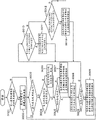
Fig. 3 is that expression is according to the flow chart of the flow process of the action of the vacuum treatment installation of embodiment shown in Figure 1.
Fig. 4 illustrates the vertical view of the integrally-built overview of the vacuum treatment installation of example according to a modification of this invention.
Fig. 5 illustrates the vertical view of the integrally-built overview of the vacuum treatment installation of example according to a modification of this invention.
Embodiment
Below, describe the embodiment according to vacuum treatment installation of the present invention with reference to the accompanying drawings in detail.
Embodiment 1
Below, utilize the description of drawings embodiments of the invention.Fig. 1 illustrates the vertical view of the integrally-built overview of vacuum treatment installation according to an embodiment of the invention.
The vacuum treatment installation that comprises vacuum processing chamber 100 according to form of implementation of the present invention shown in Figure 1 is made of atmospheric side parts 101 and inlet side parts 102 substantially.Atmospheric side parts 101 are under atmospheric pressure to carry, take in the part of location etc. as the sample of the substrate shapes such as semiconductor wafer of object being treated, and inlet side parts 102 are at the sample of substrate shapes such as transfer wafers under the pressure of atmospheric pressure decompression and at the predetermined indoor parts of handling of vacuum treatment.And, between the position and atmospheric side parts 101 of the inlet side parts 102 that carry out aforementioned conveying and processing of inlet side parts 102, be equipped with described parts to be connected configuration and have the part that makes pressure lifting between atmospheric pressure and vacuum pressure under the state of sample in inside.
In Fig. 1, though only express the observed lock chamber 108 from the top, but, in the present embodiment, dispose a plurality of same sizes along the vertical direction overlappingly or be similar to a plurality of (being two in the example of Fig. 1) lock chamber that seems identical same size.In addition, in the following description, do not having under the situation of special declaration, even for a plurality of lock chamber 108, describe as lock chamber 108 simply yet.Like this, inlet side parts 102 are to become the container that can keep the pressure of condition of high vacuum degree is coupled together and the inner parts that all are maintained at the space under the state that is depressurized.
The first vacuum conveying chamber 107, the second vacuum conveying chamber 113 are respectively to include the unit that flat shape is roughly the vacuum tank of rectangle, be two unit (being to regard two unit that do not have difference on the structure in fact as perhaps) with the structural difference that can regard identical degree in fact as.At the sidewall suitable with a face of the subtend face that is positioned at the first vacuum conveying chamber 107 and the second vacuum conveying chamber 113 each other, the configuration vacuum is carried medial compartment 114, and both are coupled together.
Vacuum is carried medial compartment 114, is that inside can be depressurized to the vacuum tank with the vacuum degree of other vacuum conveying chamber or vacuum processing chamber equal extent, interconnects with the vacuum conveying chamber, and inner chamber is interconnected.And the vacuum conveying chamber between, the valve 120 that configuration is communicated with the chamber of inside, will open, separate with cutting off at the path of inboard transfer wafers by the obturation of these valves 120, is carried vacuum between medial compartment and the vacuum conveying chamber hermetic to seal.
In the chamber of vacuum conveying medial compartment 114 inside, dispose the incorporating section, this incorporating section separates with gap mounting between the face of wafer and face and level keeps a plurality of wafers, handing-over is during wafer between first, second vacuum conveying chamber 107,113, has the function of the transporting room that an end is contained.Namely, be transported into the wafer of aforementioned incorporating section and be positioned in by the suction conveyor device people 111 in the vacuum conveying chamber, transported by the suction conveyor device people 111 in another vacuum conveying chamber, and be transported in the vacuum processing chamber or lock chamber that is connected on this vacuum conveying chamber.
Below, carry the structure of medial compartment 114 to describe for the vacuum of present embodiment, vacuum carries medial compartment 114 the same with the configuration structure of lock chamber 108, and two chambers are configured in position overlapped along the vertical direction.In more detail, vacuum is carried medial compartment 114, inside in that formation is taken in the vacuum tank in the space that inner wafer uses is equipped with its removable not shown space bar of dividing up and down, reduce two of being divided out indoor each other gas or the movement of particle.
Namely, it is the places that are accommodated in processed or processed wafer in each of a plurality of vacuum processing chambers that vacuum is carried medial compartment 114, has the possibility that produces following state: the wafer before the predetermined processing of implementing in these vacuum processing chambers to handle, in the accommodation space in this vacuum is carried medial compartment 114 under the state of standby, the wafer of accepting the processing of processing at another vacuum processing chamber is transported into the state of this accommodation space; Perhaps, the wafer of in second vacuum processing chamber 104 or the 3rd vacuum processing chamber 105, handling, in this accommodation space, wait under the holding state of any one lock chamber 108 conveying, wafer in any one of these vacuum processing chambers before the processed processing is transported into the state in this space.To this, by said structure, be suppressed at the wafer before handling and handle after wafer be present in simultaneously vacuum carry in the medial compartment 114, remain in the latter around gas and product baneful influence that the former is caused.
Particularly, in the present embodiment, plural wafer can be accommodated in to devices spaced apart between the upper surface of each wafer and lower surface along the vertical direction vacuum carry in two accommodation spaces in the medial compartment 114 about each incorporating section in, in each incorporating section, untreated wafer is received to the top, and the wafer of handling is received to the below.Thereby, in each accommodation space, remain in the deleterious effects that gas around the wafer handled and product give untreated wafer and be suppressed.
In these each incorporating sections up and down, configuration has the mounting portion of the wafer of taking in the shelf board structure that keeps plural wafer, these mounting portions are with two side wall surfaces of (left and right directions of Fig. 1) subtend of the inboard of carrying medial compartment 114 along the vacuum that constitutes the incorporating section, from they side wall surfaces towards subtend, have the outer peripheral edges portion of mounting wafer and keep the horizontal direction of wafer (among the figure as far as possible, the mode of the length direction perpendicular to drawing) is extended, and, the flange that separates the arranged spaced of regulation at above-below direction is equipped with, and, in each side wall surface side, each flange of corresponding side walls face, with identical height and the distance configuration slightly littler than the diameter of wafer, the middle body that constitutes wafer or incorporating section is vacated the shelf board structure (groove) in wide space.
Constitute the number of groove of the mounting portion of this a plurality of levels, be in the operation process of vacuum treatment installation 100, becoming at wafer be transferred between second vacuum processing chamber 104, the 3rd vacuum processing chamber 105 or the lock chamber 108 of target place during, can hold the number of the number that temporarily is maintained at mounting portion inside.That is, for the number of levels of mounting portion, be equipped with and take in as each wafer that is untreated or handled of the wafer of handling object each level of one at least.
The lock chamber 108 of present embodiment, taking in the indoor of inner wafer, the workbench of mounting wafer thereon all is equipped with, and then, the upper level fixed-site of this workbench dispose jut, described jut is the mounting wafer in the top, and at least more than one the convex shape that has that this upper end contacts with the back side.Such jut under wafer is positioned in state on this jut, constitutes in the mode of devices spaced apart between the upper end of convex shape and worktable upper surface.
Support the wafer that is accommodated in the lock chamber 108 by separating such compartment of terrain, two gate valves of closing the end, front and back (end of the above-below direction among Fig. 1) that is configured in each lock chamber 108 with the state that inside is hermetic separated under, supply gas in the inner receiving room, whereby, can make the temperature of this wafer close to desired scope.Particularly, wafer after processed in vacuum processing chamber becomes high temperature, when being transferred in atmospheric side parts 101, the cooling of the wafer after carrying out expeditiously handling in lock chamber 108 can be reduced in the generation of problems such as breakage when carrying in the atmospheric side parts 101 or damage.
For first vacuum conveying chamber 107, not with two faces that lock chamber 108 is connected with vacuum conveying chamber 114 on, first vacuum processing chamber 103 and the 4th vacuum processing chamber 106 of being connected with that inside is depressurized and coming at this delivered inside wafer wafer is handled.In this form of implementation, first~the 4th each vacuum processing chamber, expression comprise vacuum tank in the generation mechanism in the electric field of interior formation, magnetic field, comprise the vacuum pump of exhaust carried out in the whole unit of interior exhaust gear in the space that is depressurized of internal tank, in the process chamber of inside, carry out etch processes, polishing or other imposes on the processing of semiconductor wafer.In addition, be connected with pipeline at first~the 4th each vacuum processing chamber, mobile in described pipeline according to the processing gas of the processing supply of implementing.
On the first vacuum conveying chamber 107, can connect two vacuum processing chambers.In the present embodiment, be connected with first vacuum processing chamber 103 and the 4th vacuum processing chamber 106 at first vacuum processing chamber 107, still, also can only connect one of them vacuum processing chamber.On the second vacuum conveying chamber 113, can connect three vacuum processing chambers, still, in the present embodiment, only connect two vacuum processing chambers 103.
The vacuum processing chamber of present embodiment all is equipped with to have vacuum tank and inner process chamber with drum.Central portion in inner treatment chamber, dispose a sample bench cylindraceous that consistently disposes of its central shaft and cylinder, upper surface at sample bench, methods such as member by bonding spraying plating or sintering, be configured in inside and be furnished with the film of the dielectric system of membranaceous electrode, constitute the circular of mounting wafer or be similar to the mounting surface of regarding circular degree as.Be positioned in the wafer on this mounting surface, the electrostatic force by producing between film and wafer by apply direct current on the electrode of the inside that is configured in film is maintained on this mounting surface.
In addition, at a plurality of through holes of above-mentioned mounting surface configuration, a plurality of pins that move along the above-below direction of mounting surface are taken in by portion within it.These pins be projected into the mounting surface that is moved upward from lower position that is incorporated in the through hole above state under, with the front end that wafer is positioned in they or the wafer state on the mounting surface, in through hole, move upward, its front end is contacted with the back side of wafer, be moved upward again, wafer can be raised to the position of devices spaced apart above mounting surface.
Be equipped with this pin that moves up and down, the front end that carries out suction conveyor device people 111 arm enters than these front ends space on the lower, arm is lifted, perhaps make pin mobile downwards, wafer is consigned to the action of arm front end, and the arm front end that has carried out in mounting wafer move to above the mounting surface from above see under the state of the position that center wafer is consistent with the mounting surface center, pin is moved upward from through hole inside, perhaps under the state above pin is projected into mounting surface, make arm mobile downwards, wafer is consigned to comprise the pin upper end in the action of interior sample bench side.
The first vacuum conveying chamber 107 and the second vacuum conveying chamber 113, with its inside as conveying chamber, in the first vacuum conveying chamber 107, the middle body in portion space disposes suction conveyor device people 111 within it, and this suction conveyor device people 111 carries transfer wafers between in the medial compartment 114 any in lock chamber 108 and first vacuum processing chamber 103 and the 4th vacuum processing chamber 106 or vacuum under vacuum.The second vacuum conveying chamber 113 is the middle body of portion configuration within it and same suction conveyor device people 111 noted earlier also, between second vacuum processing chamber 104 and the 3rd vacuum processing chamber 105, vacuum are carried in the medial compartment 114 any, carry out the conveying of wafer.
This suction conveyor device people 111, mounting wafer on its arm, in the first vacuum conveying chamber 107, on the wafer station in being configured in first vacuum processing chamber 103 or the 4th vacuum processing chamber 106, perhaps and lock chamber 108 or vacuum carry between in the medial compartment 114 any, carry out being transported into, transporting of wafer.Carry between the conveying chamber of medial compartment 114, the first vacuum conveying chamber 107 and the second vacuum conveying chamber 113 in these first vacuum processing chambers 103 and the 4th vacuum processing chamber 106, lock chamber 108, vacuum, the path that opens and closes of the configuration using valve that can hermetic close, open 120 respectively, by mounting and remain under suction conveyor device people 111 the state of arm leading section, by the inside of this path, transfer wafers.
In having the present embodiment of said structure, utilization is configured in the wafer transport that the suction conveyor device people 111 of the first vacuum conveying chamber 107, second vacuum conveying chamber 113 inside separately carries out, in a plurality of vacuum processing chambers any and lock chamber 108 or vacuum are carried between the medial compartment 114, perhaps carry out between lock chamber 108 and vacuum conveying medial compartment 114.Except the vacuum that connects the vacuum conveying chamber more than three is carried medial compartment 114, also dispose vacuum and carry under the situation of structure of medial compartment, carry medial compartment each other in vacuum, also carry out the conveying of wafer.Wherein, comprise include and vacuum processing chamber between the situation of action of wafer transport, namely, comprise the situation of carrying out the conveying that the transports action of the wafer after being transported into or handling of wafer before processing for any of vacuum processing chamber, compare with other situation, it is elongated to move the needed time.
Can be listed below reason to this: the vacuum processing chamber of present embodiment, all be equipped with on the sample bench and suction conveyor device people between carry out wafer handing-over mobile along the vertical direction pin, the action of pin needs the time, and then, be necessary with the position of wafer with respect to the mounting surface on the sample bench with the center each other consistent mode carry out precise positioning and join, so, can not join action with too high speed.
On the other hand, vacuum is carried medial compartment 114, lock chamber 108, keep the position of wafer not mobile along the vertical direction in inside, only carry out in the movement of above-below direction by suction conveyor device people 111, in addition, position for wafer, compare with the situation that is used for the handing-over that mounting carries out to the indoor sample bench of vacuum treatment, location for suction conveyor device people 111 arm does not require high precision yet, so, can shorten more vacuum carry medial compartment 114 each other and they with lock chamber 108 between utilize suction conveyor device people 111 from one of them acceptance and transport wafer, and be transported into mounting also and move the needed time to the conveying in wherein another.
In the present embodiment, be positioned in the wafer in the wafer supporting portion of arm leading section of Atmospheric Transportation robot 112, the adsorbent equipment absorption that is configured on the wafer contact-making surface of wafer supporting portion remains in the wafer supporting portion, suppresses because the position deviation that the wafer that the action of arm causes produces at support.Particularly, the gas that has around attracting by a plurality of openings from the contact-making surface that is configured in wafer supporting portion reduces pressure, and chip sucking is attached to structure on the contact-making surface.
On the other hand, although in the wafer supporting portion of the arm leading section of suction conveyor device people 111 mounting wafers, do not implement the absorption undertaken by attracting,, contact, suppress protuberance, projection or the pin that the position is offset with wafer in the support configuration, suppress the skew of wafer by the action of arm.In addition, in order to suppress the skew of this position, suppress the responsiveness of arm or the variation ratio (acceleration) of speed, consequently, for the conveying of the wafer of same distance, suction conveyor device people 111 needs spended time, the transfer efficiency step-down of inlet side parts 102.
Below, in the present embodiment, represent such example: the time of delivery in inlet side parts 102 is reduced in the example via the time of delivery of carrying sample on the transport path of the vacuum conveying chamber, medial compartment or the vacuum processing chamber that constitute these parts, raising treatment effeciency than under the long state of the time of delivery in the atmospheric side parts 101.In addition, in the time of the indoor processing of carrying out for wafer of each vacuum treatment, below the degree identical with these time of deliveries, for the processing number of the wafer of unit interval of whole vacuum treatment installation 100, time of delivery gives bigger influence, particularly gives overriding influence.
Secondly, at such vacuum treatment installation 100, the action of the processing that wafer is carried out describes.
Be accommodated in a plurality of wafers in the box on mounting any in cassette holder 110, by any communication agency from being connected to the instruction that not shown control device on the described vacuum treatment installation 100 receives the action of regulating vacuum treatment installation 100, perhaps, reception comes from the instruction of control device of the manufacturing line that vacuum treatment installation 100 is set etc., begins to handle.Reception comes from the Atmospheric Transportation robot 112 of the instruction of control device, takes out the specific wafer in the box from box, with the wafer transport of taking out to lock chamber 108.
Carrying and accommodating in the lock chamber 108 of wafer, under the state of taking in the wafer that is transferred, shut off valve 102 and sealing, decompression is to the pressure of regulation.Afterwards, in lock chamber 108, open the valve 120 in the face of the first vacuum conveying chamber, 107 sides, lock chamber 108 is communicated with the first vacuum conveying chamber 107.
Suction conveyor device people 111 makes its arm uphold in lock chamber 108, and the wafer in the lock chamber 108 is received in the wafer supporting portion of this arm leading section, transports in the first vacuum conveying chamber 107.And then, suction conveyor device people 111, with the wafer that is positioned on this arm, by the preassigned transport path of control device, be transported into first vacuum processing chamber 103, the 4th vacuum processing chamber 116 or the vacuum that are connected on the first vacuum conveying chamber 107 and carry in the medial compartment 114 any when this wafer is taken out from box.For example, be transported to the wafer in the vacuum conveying medial compartment 114, afterwards, the suction conveyor device people 111 who is provided in the second vacuum conveying chamber 113 carries medial compartment 114 to transport the second vacuum conveying chamber 113 from vacuum, and is transported into as second vacuum processing chamber 104 or any vacuum treatment in the 3rd vacuum processing chamber 105 of above-mentioned predetermined transport path destination indoor.
In the present embodiment, valve 120 is is exclusively opened and closed.That is, be transported to vacuum and carry wafer in the medial compartment 114, by close to and the first vacuum conveying chamber 107 between the valve 120 that opens and closes, be sealed in vacuum and carry in the medial compartment 114.Afterwards, will carry the valve 120 that opens and closes between medial compartment 114 and the second vacuum conveying chamber 113 to open to vacuum, the suction conveyor device people 111 that are provided in the second vacuum conveying chamber 113 are upheld, with wafer transport in the second vacuum conveying chamber 113.Suction conveyor device people 111 will be positioned in wafer transport on its arm in second predetermined when the taking out vacuum processing chamber 104 or in the 3rd vacuum processing chamber 105 any from box.
After wafer is transported in second vacuum processing chamber 104 or the 3rd vacuum processing chamber 105 any, the valve 120 that opens and closes between the vacuum processing chamber that has been transported into wafer and the second vacuum conveying chamber 113 that is connected is closed, and this vacuum processing chamber is sealed.Afterwards, the gas of handling usefulness is imported in this process chamber, with the indoor pressure that is suitable for handling that is adjusted to of this vacuum treatment.By providing electric field or magnetic field to this vacuum processing chamber, will handle with gas exciting, in this process chamber, form plasma, wafer is handled.
To the valve 120 that opens and closes between a vacuum processing chamber being transported into and handling wafer and the second vacuum conveying chamber 113 that is attached thereto, acceptance comes from the instruction of not shown control device, close can open, obturation comprise this vacuum conveying chamber interior and the state of other valve 120 in the space that connects under, be opened.For example, not shown control device, before the valve 120 that separates out between with a vacuum processing chamber and the vacuum conveying chamber that is attached thereto is opened, send and to close or the instruction of the action of confirming to close door (path that wafer is transferred by the inside) valve 120 that open and close on other three sidewalls that are configured in this vacuum processing chamber, after affirmation is closed, open the valve 120 with a vacuum processing chamber sealing.
When detecting the disposing of wafer, valve 120 between another one vacuum processing chamber and the second vacuum conveying chamber 113 is closed, and confirm between the two by airtight sealing after, to open the valve 120 that opens and closes between a vacuum processing chamber and the second vacuum conveying chamber 113 that is connected, the wafer that suction conveyor device people 111 will handle transports its inside, when being transported into this wafer in the process chamber on the opposite transport path to lock chamber 108 transfer wafers.At this moment, also can confirm to utilize valve 120 will with situation about hermetic being sealed between any vacuum processing chamber that the first vacuum conveying chamber 107 and the second vacuum conveying chamber 113 are connected under, the valve 120 that separates out between the first vacuum conveying chamber 107 and the second vacuum conveying chamber 113 is opened.
When wafer was transported in the lock chamber 108, the valve 120 that will open and close the path that is communicated with lock chamber 108 and the first vacuum conveying chamber 107 cut out, and the first vacuum conveying chamber 107 is sealed, makes the pressure in the lock chamber 108 rise to atmospheric pressure.Afterwards, will and the inboard of basket 109 between the valve 120 that separates out open, the inside of the inside of lock chamber 108 and basket 109 is connected, Atmospheric Transportation robot 112 from lock chamber 108 with wafer transport to original box, turn back to the original position in the box.
In the present embodiment, each one, the action of each parts and the action that is configured in the transducer of their inside of formation vacuum treatment installations 100 such as each vacuum processing chamber and first, second vacuum conveying chamber 107,113, suction conveyor device people 111, Atmospheric Transportation robot 112, lock chamber 108, gate valve 120 are equipped with the control part 150 of arithmetic unit and storage device to regulate by its inside.This control part 150 can be connected by communication agency communicatedly with above-mentioned each one, via communication agency, receives the output that comes from transducer, according to the information that receives, utilize arithmetic unit to calculate command signal, send command signal via communication agency to each one, regulate their action.Being connected by the more than one interface that is configured on the control part 150 between communication agency and the control part 150 carried out.
Fig. 2 is first vacuum conveying chamber 107 shown in Figure 1 and the enlarged drawing of second vacuum conveying chamber 113.The first arm 201 and second arm 202 that suction conveyor device people 111 is equipped with transfer wafers to use.Though two arms are arranged in the present embodiment,, also can be that three or four etc. are a plurality of.
Each arm, bar portion on a plurality of (at least three in the drawings) beam connects by the axle that the joint can center on the joint mutually rotatably in end separately, speed and the angle (rotation amount) of the rotation by regulating each joint, can carry out extension or folding (contractions) of arm and move, can make by mounting and the wafer that remains on the upper surface of a distolateral hand of the front end bar portion that is disposed at a plurality of bar portion moves along specific direction.In addition, an end of the bar portion of the root side in a plurality of bar portion can be around the central portion that is connected to first vacuum conveying chamber 107 or second vacuum conveying chamber 113 along the rotating shaft of above-below direction (direction perpendicular to drawing among the figure) rotatably.And then, for the axial direction of this rotating shaft, can make the lift in height of the bar portion that is connected on the above-mentioned root, the result on each of these arms, can change the hand of leading section or be positioned in the height and position of this wafer on hand.
And then, suction conveyor device people 111 is by the position at center of shrinking in each that makes first and second arm and making the wafer that is equivalent to leading section or institute's mounting under the state close to rotating shaft, carry out the rotation around rotating shaft of above-mentioned central portion, make them uphold/shrink with respect to four doors on the sidewall of the container that is configured in the vacuum conveying chamber, make the hand of leading section be moved to the position that to pass through the subtend in the door at the state of mounting wafer.In addition, first, second arm under the state of mounting wafer on the hand on any the leading section that is configured in wherein, can make another arm flexible.
By this action, can carry out action described below, namely, wafer before an arm in two arms is keeping handling shrinks unchangeably, under the state that shrinks with the state that does not keep wafer on the another one arm, from being configured in the state that can carry out the position of above-mentioned rotation action, make another arm extension and pass through door, make this arm enter first vacuum processing chamber 103, second vacuum processing chamber 104, the 3rd vacuum processing chamber 105, in the 4th vacuum processing chamber 106 or the vacuum conveying medial compartment 114 any is indoor, acceptance is configured in the wafer after this indoor processing and shrinks, after carrying out that wafer transported outdoor action, an arm is upheld, wafer before handling is transported into this indoor and handing-over, the action of changing.Perhaps, wafer after mounting is handled on the arm in two arms also shrinks, on the another one arm, shrink in the position that can be rotated action with the state that does not keep wafer, from this state, another arm is upheld and enter vacuum by door and carry the indoor of medial compartment 114 or lock chamber 108, receive on the hand and transport after the outdoor action being configured in wafer before this indoor processing, then, arm is upheld, with the wafer after the processing that remains on the hand of leading section be transported into this indoor and configure after the replacing action withdrawed from.
In the present embodiment, except at the inlet side parts 102 interior states that wafer does not have yet from vacuum treatment installation 100, the situation of action is carried in beginning by Atmospheric Transportation robot 112, perhaps outside the situation about from inlet side parts 102, whole wafers being transported in when beginning maintenance or when finishing for batch etc., in the conveying of the wafer that utilizes suction conveyor device people 111, Atmospheric Transportation robot 112 to carry out, enforcement and box, lock chamber 108, vacuum are carried the above-mentioned replacing action between medial compartment 114 and each vacuum processing chamber.By such action, shorten the conveying of wafer and move the needed time, shorten the needed time of processing of a plurality of wafers, perhaps can improve efficiency of movement, the production capacity of vacuum treatment installation 100.
This suction conveyor device people 111 has following structure: first, second arm can be simultaneously and the equidirectional action that is rotated direction, short transverse, only with the expanding-contracting action of arm self contained function relatively.In addition, about the expanding-contracting action of arm, after an arm was upheld, with the beginning contractive action while, the another one arm can be upheld action.By this structure, keep under the situation of untreated wafer at any arm suction conveyor device people 111 shown in Figure 2, need not spinning movement, just can exchange the wafer that remains on any processing of carrying the destination untreated wafer with suction conveyor device people 111 maintenances, can improve transfer efficiency and the ability of wafer.
Below, in the vacuum treatment installation with apparatus structure shown in Figure 1, by control wafer transport, processing sequence, the method that the production efficiency of raising device is used describes.
In the present embodiment, for the whole wafers that are maintained in the box of being located on the cassette holder 110, preferably, processing time, condition are identical.Below, describe as the identical state of the treatment conditions of the wafer in the box that is arranged on the cassette holder 110 (below, being referred to as alternately, (alternate) handles).
Will be in atmospheric side parts 101 and inlet side parts 102 state of processed, the wafer carried of neither one as initial condition, begin to describe.As shown in Figure 1, in the vacuum treatment installation 100 of present embodiment, from the left side on each cassette holder 110 of the 4th, mounting the inner box that has kept a plurality of wafers.For whole wafers, determine to be carried out alternate treatment in advance.Mounting box not on the cassette holder 110 of the rightmost side, perhaps mounting the inner box that has kept a plurality of dummy wafer of using in the cleaning between the processing of wafer and the processing.
Be incorporated in the wafer in these boxes, when from box, transporting, utilize not shown control device, be predetermined the processed vacuum processing chamber of this wafer, utilize each suction conveyor device people to carry to this vacuum processing chamber.
Here, at first, the control part 150 of vacuum treatment installation 100 sends instruction, is transported in any vacuum processing chamber with any that will be accommodated in any the wafer of inside in four boxes.At this moment, in this command signal, comprise: the information of any vacuum processing chamber in the place of the target that is transferred as wafer, and, also be included in the information that treatment conditions in this process chamber, lock chamber 108 and vacuum are carried wafer handing-over transport paths such as any in the incorporating section of medial compartment 114, any in two arms of suction conveyor device people 111.In addition, among the wafer in being accommodated in the box of being located on the vacuum treatment installation 100, under the state that the processing of the specific cohort of a plurality of wafers that structure (structure of film, kind, treatment conditions etc.) is identical (below, be referred to as batch) does not begin, send this instruction.
Particularly, preferably, the setting of the conveying action of sending as command signal, up to box by mounting and till beginning to utilize the conveying action that Atmospheric Transportation robot 112 carries out during, for the whole wafers that belong to this batch, set the information of transport path and treatment conditions at control part, and be stored in the not shown storage device.In the present embodiment, send such instruction, namely, the quilt that is subordinated to this batch is positioned in first wafer 1 that is transported by Atmospheric Transportation robot 112 in any box in a plurality of boxes on the cassette holder 110, should in first vacuum processing chamber 103, handle, by any lock chamber 108, carry to first vacuum conveying chamber 107.
Wafer be transferred during, Atmospheric Transportation robot 112 takes out next processed wafer 2 according to the command signal that comes from control part 150 from any box, carry to any lock chamber 108.For this wafer 2, utilize and same control part 150 noted earlier, preestablish as any and transport path in the vacuum processing chamber of conveying target, in the present embodiment, send instruction, in order to be transported to second vacuum processing chamber 104.
Be transported into the indoor of first vacuum processing chamber 103 detecting wafer 1 by not shown transducer, the valve 120 that is configured between first vacuum processing chamber 103 and first vacuum conveying chamber 107 becomes closed condition, after the valve 120 that four doors that are communicated with the first vacuum conveying chamber 107 are opened and closed is cut out by air-tightness all and to the valve 120 that the door of the atmospheric side of any lock chamber 108 of taking in wafer 2 opens and closes, according to the command signal that comes from control part, the valve 120 that the door of the end (end of top among the figure) of the inlet side of described any lock chamber 108 is opened and closed is opened, suction conveyor device people 111 makes an arm in two arms accept wafer 2 in this lock chamber 108, and transports outdoor.At this moment, under the situation of the wafer after another arm is keeping handling, another arm is upheld, and keeps the hand of wafer to enter in this lock chamber 108, and the wafer after handling is handed off on the jut on the inner workbench.
After the valve 120 that will open cuts out, carry the valve 120 in the first vacuum conveying chamber of medial compartment 114 to open with opening and closing vacuum, arm is upheld, the wafer before handling is positioned in vacuum carries on the groove of level of top of any incorporating section in the medial compartment 114.At this moment, also can will carry the valve 120 that opens and closes between medial compartment 114 and second the vacuum conveying chamber 113 to close to vacuum, the connection each other of vacuum conveying chamber is cut off.
Then, carry after the valve 120 of first vacuum conveying chamber 107 sides of medial compartment 114 is closed in vacuum, the same with wafer 1, utilize suction conveyor device people 111 that wafer 2 is transported in second vacuum processing chamber 104.At this moment second vacuum conveying chamber 113, vacuum are carried the switching of the valve 120 that the connection between medial compartment 114 and second vacuum processing chamber 104, the 3rd vacuum processing chamber 105 opens and closes, in the mode of the connection that do not produce the inlet side parts 102 outside these chambers, exclusively carry out.
For processed next time same batch wafer 3 and the wafer 4 that belong to that is incorporated in any box, also before beginning for the action that utilizes Atmospheric Transportation robot 112 from box, to transport, utilize the control part setting to conveying and the processing of each the 3rd vacuum processing chamber 105, the 4th vacuum processing chamber 106, send command signal, begin action.
Be the membrane structure of same formation for wafer 1 to 4, under the situation about under identical conditions, handling, carry the destination in order to be transported to, with batch in next processed wafer 5 when from box, transporting, the mode that can finish at first with the processing of the wafer 1 in first vacuum processing chamber 103 is carried.Control part 150 will be set at first vacuum processing chamber 103 as the target vacuum process chamber of the conveying destination of wafer 5 before the conveying of wafer 5 begins, send the command signal of conveying.
Namely, in first vacuum processing chamber 103, after the disposing of wafer 1, by changing wafer 1 by the replacing action that is configured in the suction conveyor device people 111 in first vacuum conveying chamber 107, wafer 5 is transported into to first vacuum processing chamber 103 and is processed.On the other hand; unusual or move arbitrary reason such as bad owing to first vacuum processing chamber 103; in the moment of imagining in advance; handle under the situation that does not have to finish or do not become the state that the wafer 5 before handling can be transported into; up to second vacuum processing chamber 104 become can carry till, till the processing of the wafer 1 of the conveying standby of wafer 5 to first vacuum processing chamber 103 finishes.
Described standby, also wafer 5 can taken out from any box, be transported under any state of inside of lock chamber 108, wafer 5 is received in the lock chamber 108 implements, also can undertaken by utilizing suction conveyor device people 111 to take out and remain under the state on the arm from this lock chamber 108.Proceed the time limit of standby, become the moment of the state that the wafer 2 after the processing that becomes the wafer 2 in second vacuum processing chamber 104 finishes, handles can be transported, and become the suction conveyor device people 111 who utilizes in second vacuum conveying chamber 113 and keep wafers 2, can be transported into time difference between moment of (changing action) in second vacuum processing chamber 104 and become 0 or minimum moment.
The vacuum treatment installation 100 of above-mentioned present embodiment, expression carry out the example that four boxes on being positioned in a plurality of cassette holders 110 any respectively transports the action under the situation of a wafer.In addition, even in four boxes any, under the situation of the box that restriction transports wafer, the wafer before not having to handle in this box, each action of handling successively to a plurality of boxes of carrying each wafer in other box again also becomes equal action.
And then, also can set in the following manner, namely, before the conveying action beginning of wafer 1 or wafer 2, in each of four boxes and first vacuum processing chamber 103 that the wafer that is accommodated in each of these boxes is handled, second vacuum processing chamber 104, the 3rd vacuum processing chamber 105, the 4th vacuum processing chamber 106 any set up corresponding relation (appointment), from each of four boxes, each wafer transport, is handled in one of them to the vacuum processing chamber that corresponding relation is arranged with it.In this case, as mentioned above, do not become under the situation that the wafer before handling can be transported in the time of imagining in advance at any vacuum processing chamber, to carry the target of destination to be altered to other vacuum processing chamber, the vacuum treatment that is transported to change is indoor, and the wafer before this is handled is implemented to handle.
The conveying action that the vacuum treatment installation 100 of above-mentioned present embodiment carries out is carried out according to motion flow shown in Figure 3.In the vacuum treatment installation 100 of present embodiment, on each of first vacuum conveying chamber 107, second vacuum conveying chamber 113, respectively be connected with two vacuum processing chambers, but, carry action to be not limited to the said structure of present embodiment, also can be connected and connect separately in the structure of more than one vacuum processing chamber by each vacuum conveying medial compartment at the vacuum conveying chamber more than three, carry out same conveying action.
In addition, Fig. 3 is that expression is according to the flow chart of the motion flow of the vacuum treatment installation of embodiment shown in Figure 1.Particularly, each of a plurality of wafers of expression before for the processing in a plurality of boxes that are accommodated on each that is positioned in a plurality of cassette holders 110 is set its vacuum processing chamber of handling and order thereof or is arrived the flow process of action of the transport path of this vacuum processing chamber.According to sequence of batching products or the transport path according to the process settings of this figure, be accommodated in a plurality of wafers in above-mentioned a plurality of box be transported to as the vacuum processing chamber of the conveying destination of setting and processed after, described a plurality of wafers turn back to the original position of original box.
In addition, the prerequisite of the action shown in this figure is, the running action relevant with the processing of wafers of vacuum treatment installation 100 shown in Figure 1, normally carry out according to the command signal that comes from above-mentioned control part 150, implemented under the situation of the state of the processing of a plurality of wafers that belong to arbitrarily batch in the time that is in to expect (below, be referred to as stable state).
In this figure, the control part 150 of the action of the each several part of adjusting vacuum treatment installation 100, when the action of the running that begins vacuum treatment installation 100, obtain in advance to comprise and (for example come from more upper control unit, the host computer main frame of the whole action of a plurality of chip processing devices in the building that adjust, indication arranges vacuum treatment installation 100 etc.) instruction or the appointment etc. that comes from the user are in interior information, judgement is the running that makes box corresponding with vacuum processing chamber, namely assigns the running of box, still fixing running (step 3001) of assigning.Under the situation that makes a box and a vacuum processing chamber corresponding (appointment) running, transfer to step 3002, under the situation of the running that does not have to assign, transfer to step 3003.
Be under the situation of running that box and process chamber are assigned in running, in step 3002, each box and a plurality of vacuum processing chamber set up corresponding relation.In the present embodiment, assign four cassette holders 110 corresponding respectively separately with four vacuum processing chambers separately, but, this be in the building that vacuum treatment installation 100 is set, be transferred, be positioned between each box on each cassette holder 110 and each vacuum processing chamber and set up corresponding relation, under the state that is positioned at a plurality of boxes on each cassette holder 110, setting up corresponding relation between a box and a vacuum processing chamber, is identical structure technically.
Secondly, in step 3003, control part detects the wafer that whether has in each box that is positioned on the cassette holder 110 before handling.Under the situation that wafer before being untreated does not all have in box, wafer in these boxes was handled, and will take in the box of untreated wafer, was transported in the vacuum treatment installation 100, exchange with the box of taking in the wafer of handling, standby is till can transport wafer in the box.
Secondly, when taking in untreated wafer in control part detects box on the cassette holder 110, detecting this untreated wafer has and does not have the setting of above-mentioned conveying (step 3004).Wafer before whole processing in being accommodated in box, be carried out under the situation of this conveying setting, be the moment of foundation from moment that host control devices such as control part or main frame are set or with the instruction that comes from the user, beginning transfer wafers, the running of handling.
In above-mentioned steps 3004, when detecting the wafer of carrying before setting uncertain processing, control part sends instruction, carry out the setting of carrying to (appointment) vacuum processing chamber corresponding with the box of taking in this wafer and the setting (step 3005) of carrying out the treatment conditions in this vacuum processing chamber.This instruction comprises carries the vacuum processing chamber of destination and the treatment conditions of this wafer in this vacuum processing chamber to conduct that should wafer.
On the other hand, under the situation that detects the untreated wafer of not carrying out above-mentioned setting, according to the instruction that comes from control part, the processing of beginning untreated wafer.At least one wafer that above-mentioned treatment conditions or transport condition are set from the moment that control part is set, is begun to carry, and is carried out processing.
In the present embodiment, at first, control part is set the transport condition of above-mentioned wafer, in order to begin to carry out the conveying of the wafer in the box, wherein, described box with close to basket 109, namely be configured in the forefront of vacuum treatment installation 100 and first vacuum processing chamber 103 that is connected with first vacuum conveying chamber 107 on being connected to lock chamber 108 or the 4th vacuum processing chamber 106 any is corresponding.In this transport condition, include movement schedule, this movement schedule comprises this untreated wafer with respect to the sequence of batching products of other untreated wafer, in fact carry beginning or by, be trapped in the moment on the path, transport path (vacuum processing chamber, vacuum conveying chamber.Vacuum is carried medial compartment, lock chamber etc.).
On the other hand, under the situation of the untreated wafer that the setting in not being assigned to the box that is connected to two vacuum processing chambers on first vacuum conveying chamber 107 finishes, perhaps detecting the moment that can transport in the lock chamber 108 of this untreated wafer at inlet side parts 102 in first vacuum conveying chamber 107, these vacuum processing chambers can not transport under the situation that is configured in inner wafer, control part is set the movement schedule of this wafer, conveying with the wafer in beginning and any corresponding box in the vacuum processing chamber, wherein, described vacuum processing chamber is connected with the vacuum conveying chamber that is connected the inboard that is configured in the first vacuum conveying chamber 107.
Like this, the vacuum treatment installation 100 of present embodiment, with from the vacuum conveying chamber of the most close front side to (one the most inboard side nearby) vacuum conveying chamber of the most inboard vacuum conveying chamber adjacency, the mode of the untreated wafer that any the corresponding box in the vacuum processing chamber on carrying (forward transmitting) successively and being connected to each of these vacuum conveying chambers is interior is set the transport condition of these wafers.Forward transmit whether finish (step 3006) afterwards the above-mentioned of vacuum processing chamber that detects to being connected on the above-mentioned innermost vacuum processing chamber nearby, begin (step 3007) this forward transmission according to said sequence.In the present embodiment, in the conveying that forward transmits, with with the mode of wafer transport in first vacuum processing chamber 103 that is connected on first vacuum conveying chamber 107, set the movement schedule of the untreated wafer in the box that is assigned to first vacuum processing chamber 103.
Secondly, control part is set the conveying program of this untreated wafer untreated wafer transport is connected to the mode in the whole vacuum processing chambers on the innermost vacuum conveying chamber.That is, set the movement schedule (step 3008) that is assigned to the untreated wafer in each box that is connected to each vacuum processing chamber on the innermost vacuum conveying chamber.In the present embodiment, to carry the mode that is accommodated in corresponding to the wafer in the box of (being assigned to) this vacuum conveying chamber to being connected in second vacuum processing chamber 104 on the second vacuum conveying chamber 113 and the 3rd vacuum processing chamber 105, set movement schedule for this wafer.
Secondly, with to be connected to one of innermost vacuum conveying chamber nearby among the vacuum processing chamber on the vacuum conveying chamber of side, carrying out above-mentioned mode of not carrying the vacuum processing chamber transfer wafers of untreated wafer when forward transmitting, set to be assigned to (corresponding to) movement schedule of untreated wafer in the box of this vacuum processing chamber.In the present embodiment, respectively to carry one to be accommodated in each the mode of untreated wafer of two box inside separately that is assigned to these vacuum processing chambers to second vacuum processing chamber 104 and the 3rd vacuum processing chamber 105, set the movement schedule of this wafer.
Afterwards, with to be connected to one of innermost vacuum conveying chamber nearby the vacuum processing chamber on (adjacency) vacuum conveying chamber before vacuum conveying chamber more close of side carry the mode of the untreated wafer in the box that is assigned to this vacuum processing chamber, set the conveying of this wafer, with vacuum processing chamber that each vacuum conveying chamber till first vacuum conveying chamber 107 of the forefront side that is configured in vacuum treatment installation 100 is connected among, to carry the mode of (oppositely transmitting) untreated wafer to the vacuum processing chamber that in forward the transmitting of step 3007, is not transferred wafer, set the movement schedule (step 3010) of the untreated wafer in the box that is assigned to this vacuum processing chamber.In the present embodiment, in the 4th vacuum processing chamber 106 that is connected on first vacuum conveying chamber 107, to carry the mode of the untreated wafer in the box that is assigned to it, set the movement schedule of this wafer.
In above-mentioned appointment running, under its stable state, up to being connected to after one of innermost vacuum conveying chamber only the forward transmission till the vacuum processing chamber on the vacuum conveying chamber of front side finishes, till in the whole vacuum processing chambers that are connected on the innermost vacuum conveying chamber, being transported into before the wafer, be not transported into wafer in the vacuum processing chamber on the vacuum conveying chamber that is connected to nearby.Namely, in above-mentioned operation process, when implementing the action of vacuum treatment installation 100 according to the movement schedule that the untreated wafer that is accommodated in each box is set, the processed number of wafer is more than the number of the vacuum conveying chamber that constitutes vacuum treatment installation 100, and with wafer transport to be connected to the inside the vacuum conveying chamber on whole vacuum processing chambers in, under situation about can not further carry again, with beginning on the vacuum conveying chamber that is connected to side nearby, also do not carry out the vacuum processing chamber transfer wafers of wafer transport and the mode that begins to handle, set the transport condition of wafer and also implemented.
On the other hand, in step 3001, running as vacuum treatment installation 100, do not set up under the situation of non-appointment running of corresponding relation setting box and vacuum processing chamber for, running is the same with assigning, in step 3003, in the wafer before the processing of detection in being accommodated in the box of mounting on cassette holder 110, whether the wafer of not setting mail message is arranged.Under the situation that does not detect such wafer, since be wafer in the box be all handled or all set transport condition, so, standby is transported to vacuum treatment installation 100 to the box of taking in the untreated wafer of not setting movement schedule, box exchange with having taken in the wafer of handling can transport till the wafer from the box of having taken in untreated wafer.
In the present embodiment, afterwards, transfer to step 3006, carry out the setting of the conveying that forward transmits of above-mentioned steps 3007.Namely, from the vacuum conveying chamber (first vacuum conveying chamber 107) that is connected to the forefront side on the lock chamber 108 up to the vacuum conveying chamber of a front side adjacency of innermost vacuum conveying chamber till, in any vacuum processing chamber that is connected on each vacuum conveying chamber, to carry the mode of the untreated wafer in each any box that is positioned on the cassette holder 110, set the movement schedule of this wafer.And then, transfer to step 3008, in the whole vacuum processing chambers that are connected on the innermost vacuum conveying chamber, to carry the mode of untreated wafer, set the movement schedule of this wafer.
In the present embodiment, to carry the mode of untreated wafer in separately successively to being connected to second vacuum processing chamber 104 on second vacuum conveying chamber and the 3rd vacuum conveying chamber 105, set the movement schedule of two untreated wafer.In the vacuum treatment installation 100 of present embodiment, judge whether to carry out the reverse conveying of step 3010.Carrying out non-appointment running, oppositely not transmitting under the situation of running, transfer to step 3011.
Afterwards, in the preferential mode of implementing of the processing that is connected the wafer in the vacuum processing chamber on the innermost vacuum conveying chamber, set movement schedule.In step 3011, in the vacuum processing chamber of setting on being connected to innermost vacuum conveying chamber, carry after the untreated wafer, be to be connected under the situation of the vacuum processing chamber on the innermost vacuum conveying chamber being envisioned for the vacuum processing chamber that can be transported into untreated wafer the earliest, control part is to carry the mode of untreated wafer to set the movement schedule of this untreated wafer to this vacuum processing chamber.
Namely, the control part 150 of present embodiment, for its movement schedule being set at the untreated wafer of being carried by the next one successively that is transported to the untreated wafer arbitrarily in the vacuum processing chamber that is connected on the innermost vacuum processing chamber, to the innermost vacuum processing chamber of lighting, can be transported into the earliest wafer from the special time that calculates according to transport condition, to carry the mode of untreated wafer, set the action of the each several part of suction conveyor device people 111 equal vacuum processing unit 100.
In the present embodiment, control part is taking out from box and is carrying as the above-mentioned next untreated wafer that is transferred successively, till the time point that wafer can be transported in the inboard of the vacuum conveying chamber of the front side adjacency of innermost vacuum conveying chamber, detection can become the vacuum processing chamber (step 3011) that wafer is transported into the earliest, be to be connected under the situation of any vacuum processing chamber on the innermost vacuum conveying chamber at this vacuum processing chamber, in the mode that aforementioned untreated wafer is carried to this vacuum processing chamber, set movement schedule (step 3012).
Specifically, valve 120 at the inlet side of the lock chamber 108 of opening present embodiment, the untreated wafer that is incorporated in inside and is depressurized becomes the time point that untreated wafer can be transported into first vacuum conveying chamber 107 inside, detecting second vacuum processing chamber 104 that is connected on second vacuum conveying chamber 113, in the 3rd vacuum processing chamber 105 any can earlier be transported under the situation of wafer than in first vacuum processing chamber 103 or the 4th vacuum processing chamber 106 any, become the vacuum processing chamber that can be transported in early days in order to be transported into, untreated wafer is transported to vacuum by suction conveyor device people 111 and carries medial compartment 114 inside.
If, become and to be transported under the situation of wafer the earliest being judged to be vacuum processing chamber outside the vacuum processing chamber that is connected on the innermost vacuum conveying chamber, detection becomes the vacuum processing chamber of transfer wafers the earliest among being connected to vacuum processing chamber on the more than one vacuum conveying chamber of front side of innermost vacuum conveying chamber, to carry the mode of aforementioned untreated wafer to this vacuum processing chamber, set the movement schedule of this wafer.Namely, in step 3013, control part takes out and carries the untreated wafer of being carried by the next one successively as above-mentioned from box, time point up to the vacuum conveying chamber inboard of further one the front side adjacency of the vacuum conveying chamber that becomes the place ahead adjacency that wafer can be transported into innermost vacuum conveying chamber detects and becomes the vacuum processing chamber that can the earliest wafer be transported into.In such a way, set the movement schedule of untreated wafer, described mode is, be and be connected under the situation of the vacuum processing chamber that the vacuum processing chamber on the vacuum conveying chamber of the front side of innermost vacuum conveying chamber adjacency is connected at this vacuum processing chamber, described wafer is transported in this vacuum processing chamber, be not under such situation, with described wafer be transported into comprise adjacency (further one front side) vacuum conveying chamber interior, be connected to the vacuum treatment indoor (step 3014) that can be transported into wafer the earliest that becomes in the vacuum processing chamber on the vacuum conveying chamber of front side more.
Specifically, opening the valve 120 of lock chamber 108 at inlet side, the untreated wafer that is incorporated in inside and is depressurized becomes the time point that untreated wafer can be transported into first vacuum conveying chamber 107 inside, in detecting first vacuum processing chamber 103 or the 4th vacuum processing chamber 106 any can be than second vacuum processing chamber 104 that is connected on the second vacuum conveying chamber 113, when any in the 3rd vacuum processing chamber 105 earlier carried untreated wafer, utilize the suction conveyor device people 111 in first vacuum conveying chamber 107 in lock chamber 108, untreated wafer to be transported to this vacuum conveying chamber.
Under the situation of the vacuum treatment installation that is equipped with the vacuum conveying chamber more than three, have such situation: side has than the vacuum processing chamber on the vacuum conveying chamber of one the front side that is connected to above-mentioned innermost vacuum conveying chamber forwardly becomes the vacuum processing chamber that can earlier be transported into untreated wafer.In this case, control part is set the movement schedule of next untreated wafer, and this movement schedule for being configured in the vacuum conveying chamber of side and the vacuum processing chamber that is attached thereto more on the front, carries out the setting process of above-mentioned movement schedule.
Vacuum treatment installation 100 according to the present embodiment that carries out this non-appointment running, control part is with among the wafer in being included in batch, be configured to the mode that the number of wafer processed in the more inboard vacuum processing chamber of vacuum treatment installation 100 becomes bigger in connection, set the conveying of untreated wafer, make the vacuum treatment installation action.That is, set for and made before the processing of untreated wafer begins, untreated wafer is transported in the vacuum processing chamber of the end process more early in the middle of the vacuum processing chamber that is connected on the more inboard vacuum conveying chamber.
More particularly, vacuum treatment installation 100 is according to the instruction that comes from control part, for untreated wafer arbitrarily, from the most inboard to front side, with each vacuum conveying chamber and in the vacuum conveying chamber of its place ahead adjacency two as object, in the vacuum conveying chamber that becomes the place ahead in the middle of can be to them, be transported into the time point of untreated wafer, detection is connected to the vacuum processing chamber that can be transported into wafer the earliest that becomes in the middle of the vacuum processing chamber on described two vacuum conveying chambers, be to be connected under the situation of the vacuum processing chamber on the vacuum conveying chamber at rear at this vacuum processing chamber, so that this untreated wafer is transported to the mode of handling in this vacuum processing chamber, set the movement schedule of this wafer by control part.If become under the situation that can be transported in early days at the vacuum processing chamber that is connected on the vacuum conveying chamber in the place ahead, as object, carry out the above-mentioned detection that becomes the vacuum processing chamber that can be transported in early days with the vacuum conveying chamber in this place ahead and a vacuum conveying chamber more on the front repeatedly.
In vacuum treatment installation 100, carry out conveying and the processing of wafer by setting according to such conveying, only to the cohort that is accommodated in a plurality of wafers in the box (batch) carry out continuously from box, taking out count, under the situation of the processing of wafer till after living through handling, turning back in the original box, the needed time of the processing of this batch shortens, consequently, the processing number (production capacity) of unit interval improves.In addition, assigning under the situation of running, for in a plurality of boxes each, make wafer that its inside takes in and each of a plurality of vacuum processing chambers set up corresponding relation, can easily grasp characteristic and the experience of the processing of each box, and, by making the treatment characteristic in each process chamber identical or approximate for each box, for each batch, can be adjusted in the processing of carrying out after the processing of each batch that is undertaken by this vacuum treatment installation 100, consequently, improve the reproducibility of rate of finished products and processing.In addition, going out under the unusual situation for wafer inspection arbitrarily because wafer and batch and the corresponding relation of vacuum processing chamber be clear and definite, so, can by take place specific batch of unusual wafer prediction all unusually, easily carry out the detection of reason.
In addition, under the situation of assigning running, also can after the release that forward transmits of step 3008, replace the conveying of the reverse transmission of step 3010, transfer to step 3011, make to the preferential running of conveying of the vacuum processing chamber of inboard.In addition, in the vacuum treatment installation 100 that carries out above-mentioned running, be configured on the wafer transport path and conduct maintenance at least temporarily, the Atmospheric Transportation robot 112 in the place of being detained, lock chamber 108, suction conveyor device people 111 in first vacuum conveying chamber 107, vacuum is carried medial compartment 114, suction conveyor device people 111 in second vacuum conveying chamber 113, by control part with the wafer transport of carrying out in the short as far as possible time just on the path, being transferred from the place of the upstream side action to the wake flow side, be the mode of the action of so-called first-in first-out, regulate its action.
After box was transferred and is positioned on the cassette holder 110, control part was accommodated in the setting of the conveying of the untreated wafer in this box immediately.Particularly, before the conveying of this wafer began, the control part utilization was stored in the software that is disposed in its inner storage device such as RAM, calculated the time relevant with the conveying action of wafer by arithmetic unit.
At this moment, because the beginning with the action of suction conveyor device people 111 in the conveying of each wafer, the moment that finishes, and the on-off action of valve 120 begins, carry the time of relevant action the finish times etc., because of the difference of setting of transport path and order different, so, comprise these transport paths for making, sequential scheduling is in the different a plurality of progresses of interior transport condition, carry out above-mentioned calculating, selection is taken out this wafer to the time of returning from box, and then from as the cohort of a plurality of wafers batch initial wafer be fetched to the time that last wafer returns and become minimum transport condition, it is set.
By implementing above-mentioned control, each the suction conveyor device people of decentralized configuration in the vacuum conveying chamber conveying is loaded, and can improve the production efficiency of whole device.
Secondly, utilize Fig. 4 and Fig. 5, for proceeding in processing after certain degree, in any vacuum processing chamber, detect the state that abnormality, the processing in this vacuum processing chamber stop, describing.
Fig. 4 is in the vacuum treatment installation that schematically is illustrated in according to embodiment shown in Figure 1, and the vertical view of unusual state takes place in specific vacuum processing chamber.By the alternate treatment the same with embodiment shown in Figure 1, wafer is handled.Vacuum treatment installation 100 shown in Figure 4, the same with Fig. 1, have such structure, namely, each two vacuum processing chambers dispose side by side along fore-and-aft direction, from forward observation, about (among the figure about) direction connecting interconnective two vacuum conveying chambers.
In this example, first vacuum processing chamber 103 is drawn hacures, be illustrated in and assign in the running, at the time point that the processing of a plurality of wafers finishes, first vacuum processing chamber 103 is because the unusual state that stops arbitrarily.When generation is unusual in first vacuum processing chamber 103, control part 150 sends instruction to various piece, regulate its action, make the wafer of carrying in the way temporarily return original reception position in the original box, do not restart to carry out the conveying of the processing usefulness of untreated wafer.And then the wafer in the middle of handling in any in second vacuum processing chamber 104, the 3rd vacuum processing chamber 105, the 4th vacuum processing chamber 106 after its processing finishes, with top described the same, turns back to the original position of original box.
And then for the wafer that takes place in first unusual vacuum processing chamber 103, if possible, control part also in the mode of the action of the original position of carrying out transporting and return original box from this process chamber, is regulated its action.The transporting and return under the situation of difficult of wafer in being judged as first vacuum processing chamber 103, with open and close be communicated with between first vacuum processing chamber 103 and first vacuum conveying chamber 107 valve 120 hermetic close, first vacuum processing chamber 103 inside are hermetic separated out.
In this state, after wafer in carrying the way and the wafer in processing turn back in the box, a wafer is not transported in three vacuum processing chambers yet, and first vacuum processing chamber 103 is in halted state, and other vacuum processing chamber performs the preparation of the processing of beginning wafer.Afterwards, utilize other zoning and the atmospheric side parts 101 of inlet side parts 102, the processing of the wafer in the box is proceeded in entry into service again, and, as required, carry out maintenance, inspection operation in first vacuum processing chamber 103.
From above-mentioned state, among by the untreated wafer in the box of control part appointment, by the wafer of initial delivery, in the action of forward carrying, in the mode of carrying to the 4th vacuum processing chamber 106, set the progress of carrying again.Then, in the mode that the untreated wafer that will take out is carried to any vacuum processing chamber that is connected on second vacuum conveying chamber 113 according to the action of step 3008, set the condition of carrying from box.
And then Fig. 5 is the vertical view that schematically is illustrated in according to unusual state takes place in the specific vacuum processing chamber in the vacuum treatment installation of embodiment shown in Figure 1.In this figure, utilization and the same alternate treatment of Fig. 1 are carried out the processing of wafer.This figure is the structure with the same device that is connected with four vacuum processing chambers of Fig. 1, but, be be in that a plurality of processing of wafers finish and in four vacuum processing chambers a wafer be not transported into the state that the 3rd vacuum processing chamber 105 stops owing to reason arbitrarily yet.In this state, under the situation of carrying three wafers, control part 150 is according to the motion flow of above-mentioned running, at first to carry the mode of first wafer to control to first vacuum processing chamber 103., controlled in the mode that second wafer carried to second vacuum processing chamber 104 by after first vacuum processing chamber is transported at wafer.And the 3rd wafer be not by to the 3rd vacuum processing chamber 105 but carried to the 4th vacuum processing chamber 106.
According to said structure, in vacuum treatment installation 100, even in vacuum processing chamber, take place under the unusual situation, the control method of wafer transport is constant basically, detects unusual vacuum processing chamber and stops, and separates with other container air-tightness areas of inlet side parts 102, and, regulate, so that when entry into service again, the vacuum processing chamber that initial untreated wafer should be carried to the next one is carried.In addition, as described in above-mentioned embodiment, from close to basket 109, be configured in first vacuum conveying chamber of side nearby to the vacuum conveying chamber of the inside, the vacuum processing chamber of the abnormality on being connected to each vacuum conveying chamber, respectively carry a wafer to any of the vacuum processing chamber of stable state successively, begin to handle, by carrying out such control, the conveying load that is configured in each the suction conveyor device people in the vacuum conveying chamber is disperseed, can improve the production efficiency of whole device.
Claims (9)
1. vacuum treatment installation comprises: a plurality of vacuum conveying chambers, and described a plurality of vacuum conveying chambers are configured in the rear side of Atmospheric Transportation chamber, interconnect, and the suction conveyor device people of transfer wafers is arranged in the internal configurations that is depressurized; A plurality of vacuum processing chambers, on each of described vacuum conveying chamber, at least respectively connect a described vacuum processing chamber, take out from this box at a plurality of wafers that utilize described suction conveyor device people will be configured in the box of front face side of aforementioned Atmospheric Transportation chamber, carry to aforementioned a plurality of vacuum processing chambers successively, and handle, afterwards, described wafer is turned back in the aforementioned box, wherein
Described vacuum treatment installation has the action of the conveying of setting aforementioned a plurality of wafers and regulates the control part of this action, this control part is regulated, make aforementioned wafer arbitrarily be transported to be connected and be configured among aforementioned a plurality of vacuum conveying chamber in the whole aforementioned vacuum processing chamber on the most inboard vacuum conveying chamber, after regulating like this, conveying to next wafer is regulated, make that become at aforementioned wafer arbitrarily can be from being connected to before aforementioned vacuum processing chamber on the most inboard described vacuum conveying chamber transports, with this next one wafer transport in the vacuum processing chamber that is configured in rear as the aforementioned vacuum processing chamber that can be transported into.
2. vacuum treatment installation as claimed in claim 1 is characterized in that,
Aforementioned control part is regulated the conveying of aforementioned next wafer, make aforementioned next wafer transport in following vacuum processing chamber, that is, this vacuum processing chamber be connected to dispose than the aforementioned a plurality of vacuum processing chambers on the most inboard aforementioned aforementioned vacuum conveying chamber aforementioned vacuum conveying chamber on the front among, be connected to the vacuum processing chamber on the vacuum conveying chamber at aforementioned rear.
3. vacuum treatment installation as claimed in claim 1 is characterized in that,
Comprise: medial compartment, described medial compartment disposes these vacuum conveying chambers each other at adjacent aforementioned a plurality of vacuum conveying chambers with coupling together, and the inside being communicated with aforementioned vacuum conveying chamber can hold a plurality of aforementioned wafers; At least one lock chamber, described lock chamber dispose vacuum conveying chamber and the aforementioned Atmospheric Transportation chamber of aforementioned arrangements in the forefront between the vacuum conveying chamber and aforementioned Atmospheric Transportation chamber that are configured in the forefront among aforementioned a plurality of vacuum conveying chambers with coupling together,
Utilize the conveying of the aforementioned wafer that aforementioned suction conveyor device people carries out, the needed time of conveying between aforementioned vacuum processing chamber and aforementioned medial compartment or aforementioned lock chamber, longer than the needed time of conveying between aforementioned medial compartment or aforementioned lock chamber.
4. vacuum treatment installation as claimed in claim 2 is characterized in that,
Comprise: medial compartment, described medial compartment disposes these vacuum conveying chambers each other at adjacent aforementioned a plurality of vacuum conveying chambers with coupling together, and the inside being communicated with aforementioned vacuum conveying chamber can hold a plurality of aforementioned wafers; At least one lock chamber, described lock chamber dispose vacuum conveying chamber and the aforementioned Atmospheric Transportation chamber of aforementioned arrangements in the forefront between the vacuum conveying chamber and aforementioned Atmospheric Transportation chamber that are configured in the forefront among aforementioned a plurality of vacuum conveying chambers with coupling together,
Utilize the conveying of the aforementioned wafer that aforementioned suction conveyor device people carries out, the needed time of conveying between aforementioned vacuum processing chamber and aforementioned medial compartment or aforementioned lock chamber, longer than the needed time of conveying between aforementioned medial compartment or aforementioned lock chamber.
5. vacuum treatment installation as claimed in claim 1 is characterized in that,
Comprise: medial compartment, described medial compartment disposes these vacuum conveying chambers at adjacent aforementioned a plurality of vacuum conveying chambers each other with coupling together, and the inside being communicated with aforementioned vacuum conveying chamber can hold a plurality of aforementioned wafers; At least one lock chamber, described lock chamber is between the vacuum conveying chamber and aforementioned Atmospheric Transportation chamber that are configured in the forefront among aforementioned a plurality of vacuum conveying chambers, vacuum conveying chamber and the aforementioned Atmospheric Transportation chamber of aforementioned arrangements in the forefront disposed with coupling together, can hold aforementioned wafer in inside
Each comfortable inside of aforementioned a plurality of vacuum processing chamber is equipped with sample bench, aforementioned wafer is by mounting and remain on the upper surface of this sample bench, described sample bench comprises: a plurality of pins, described a plurality of pin be configured in this sample bench inside, move up and down, under the state that front end is moved upward from aforementioned upper surface, with aforementioned wafer mounting and remain on this front end; The film of dielectric system, described film constitutes aforementioned upper surface, by the electrostatic force that forms under the state that wafer is positioned on this film, adsorbs and keep aforementioned wafer,
Described vacuum treatment installation is equipped with in aforementioned medial compartment and aforementioned lock chamber mounting and keeps the fixing maintaining part of aforementioned wafer.
6. vacuum treatment installation as claimed in claim 2 is characterized in that,
Comprise: medial compartment, described medial compartment disposes these vacuum conveying chambers at adjacent aforementioned a plurality of vacuum conveying chambers each other with coupling together, and the inside being communicated with aforementioned vacuum conveying chamber can hold a plurality of aforementioned wafers; At least one lock chamber, described lock chamber is between the vacuum conveying chamber and aforementioned Atmospheric Transportation chamber that are configured in the forefront among aforementioned a plurality of vacuum conveying chambers, vacuum conveying chamber and the aforementioned Atmospheric Transportation chamber of aforementioned arrangements in the forefront disposed with coupling together, can hold aforementioned wafer in inside
Each comfortable inside of aforementioned a plurality of vacuum processing chamber is equipped with sample bench, aforementioned wafer is by mounting and remain on the upper surface of this sample bench, described sample bench comprises: a plurality of pins, described a plurality of pin be configured in this sample bench inside, move up and down, under the state that front end is moved upward from aforementioned upper surface, with aforementioned wafer mounting and remain on this front end; The film of dielectric system, described film constitutes aforementioned upper surface, by the electrostatic force that forms under the state that wafer is positioned on this film, adsorbs and keep aforementioned wafer,
Described vacuum treatment installation is equipped with in aforementioned medial compartment and aforementioned lock chamber mounting and keeps the fixing maintaining part of aforementioned wafer.
7. vacuum treatment installation as claimed in claim 1 is characterized in that,
Respectively carry an aforementioned wafer each of aforementioned vacuum processing chamber on from from the vacuum conveying chamber of forefront side among aforementioned a plurality of vacuum conveying chambers to the vacuum conveying chamber that is connected to each rear, carry aforementioned wafer to the whole aforementioned vacuum processing chamber that is connected on the most inboard aforementioned vacuum conveying chamber, afterwards, regulate the conveying of aforementioned next wafer, before making aforementioned wafer in being transported to the aforementioned vacuum processing chamber that is connected on the most inboard aforementioned vacuum conveying chamber become can from this vacuum processing chamber, to transport, with this next one wafer transport in the vacuum processing chamber that is configured in rear as the aforementioned vacuum processing chamber that can be transported into.
8. vacuum treatment installation as claimed in claim 2 is characterized in that,
Respectively carry an aforementioned wafer each of aforementioned vacuum processing chamber on from from the vacuum conveying chamber of forefront side among aforementioned a plurality of vacuum conveying chambers to the vacuum conveying chamber that is connected to each rear, carry aforementioned wafer to the whole aforementioned vacuum processing chamber that is connected on the most inboard aforementioned vacuum conveying chamber, afterwards, regulate the conveying of aforementioned next wafer, before making aforementioned wafer in being transported to the aforementioned vacuum processing chamber that is connected on the most inboard aforementioned vacuum conveying chamber become can from this vacuum processing chamber, to transport, with this next one wafer transport in the vacuum processing chamber that is configured in rear as the aforementioned vacuum processing chamber that can be transported into.
9. vacuum treatment installation comprises: a plurality of vacuum conveying chambers, and described vacuum conveying chamber is configured in the rear side of Atmospheric Transportation chamber, interconnects, and in the inside that is depressurized, disposes the suction conveyor device people of transfer wafers; A plurality of vacuum processing chambers, on each of described vacuum conveying chamber, at least respectively connect a described vacuum processing chamber, a plurality of wafers in a plurality of boxes on utilizing described suction conveyor device people to be positioned in to be disposed at a plurality of box platforms of aforementioned Atmospheric Transportation chamber front face side take out from this box, the vacuum processing chamber that has a corresponding relation with this box among aforementioned a plurality of vacuum processing chambers is carried successively, and handle, afterwards, aforementioned wafer is turned back in the aforementioned box, wherein
Described vacuum treatment installation has the conveying action of setting aforementioned a plurality of wafers and the control part of regulating this action, this control part is regulated, in order to from each of aforementioned a plurality of boxes, respectively take out a wafer successively, and the vacuum conveying chamber of the forefront side among aforementioned a plurality of vacuum conveying chambers is respectively carried an aforementioned wafer to being connected to each of aforementioned vacuum processing chamber on each the most inboard aforementioned vacuum conveying chamber, with aforementioned wafer transport in the whole aforementioned vacuum processing chamber that is connected on the most inboard aforementioned vacuum conveying chamber, afterwards, with in the vacuum processing chamber of aforementioned wafer transport to each vacuum conveying chamber that is connected to till the vacuum conveying chamber of aforementioned forefront each.
Applications Claiming Priority (2)
| Application Number | Priority Date | Filing Date | Title |
|---|---|---|---|
| JP2012-003692 | 2012-01-12 | ||
| JP2012003692A JP2013143513A (en) | 2012-01-12 | 2012-01-12 | Vacuum processing apparatus |
Publications (1)
| Publication Number | Publication Date |
|---|---|
| CN103208441A true CN103208441A (en) | 2013-07-17 |
Family
ID=48755623
Family Applications (1)
| Application Number | Title | Priority Date | Filing Date |
|---|---|---|---|
| CN2012100545875A Pending CN103208441A (en) | 2012-01-12 | 2012-03-05 | Vacuum Processing Apparatus |
Country Status (5)
| Country | Link |
|---|---|
| US (1) | US20130183121A1 (en) |
| JP (1) | JP2013143513A (en) |
| KR (1) | KR101338229B1 (en) |
| CN (1) | CN103208441A (en) |
| TW (1) | TWI471968B (en) |
Cited By (3)
| Publication number | Priority date | Publication date | Assignee | Title |
|---|---|---|---|---|
| CN109936340A (en) * | 2017-12-19 | 2019-06-25 | 成都晶宝时频技术股份有限公司 | A kind of quartz resonator continuous fine adjustment system and method |
| CN110577082A (en) * | 2018-06-08 | 2019-12-17 | 徽拓真空阀门有限公司 | Wafer transfer unit and wafer transfer system |
| WO2021204050A1 (en) * | 2020-04-10 | 2021-10-14 | 北京北方华创微电子装备有限公司 | Semiconductor processing device |
Families Citing this family (13)
| Publication number | Priority date | Publication date | Assignee | Title |
|---|---|---|---|---|
| JP5785712B2 (en) * | 2010-12-28 | 2015-09-30 | 株式会社日立ハイテクノロジーズ | Vacuum processing equipment |
| US9117865B2 (en) * | 2012-04-12 | 2015-08-25 | Applied Materials, Inc. | Robot systems, apparatus, and methods having independently rotatable waists |
| JP2014036025A (en) * | 2012-08-07 | 2014-02-24 | Hitachi High-Technologies Corp | Vacuum processing apparatus or operation method of vacuum processing apparatus |
| JP6002532B2 (en) * | 2012-10-10 | 2016-10-05 | 株式会社日立ハイテクノロジーズ | Vacuum processing apparatus and vacuum processing method |
| KR101530024B1 (en) * | 2013-12-20 | 2015-06-22 | 주식회사 유진테크 | Substrate processing module, substrate processing apparatus and substrate transfering method including the same |
| KR102238649B1 (en) * | 2014-09-16 | 2021-04-09 | 삼성전자주식회사 | Bonding apparatus of semiconductor chip |
| JP6430889B2 (en) * | 2015-05-13 | 2018-11-28 | 株式会社日立ハイテクノロジーズ | Vacuum processing apparatus and operation method thereof |
| US10062599B2 (en) * | 2015-10-22 | 2018-08-28 | Lam Research Corporation | Automated replacement of consumable parts using interfacing chambers |
| JP6718755B2 (en) * | 2016-06-22 | 2020-07-08 | 株式会社日立ハイテク | Vacuum processing apparatus and operating method thereof |
| JP2019537253A (en) | 2016-10-18 | 2019-12-19 | マットソン テクノロジー インコーポレイテッドMattson Technology, Inc. | System and method for processing a workpiece |
| US11482434B2 (en) | 2016-10-18 | 2022-10-25 | Belting E-Town Semiconductor Technology Co., Ltd | Systems and methods for workpiece processing |
| US11077535B2 (en) * | 2018-02-14 | 2021-08-03 | Samsung Electronics Co., Ltd. | Process system having locking pin and locking pin |
| US11293551B2 (en) | 2018-09-30 | 2022-04-05 | ColdQuanta, Inc. | Break-seal system with breakable-membrane bridging rings |
Citations (3)
| Publication number | Priority date | Publication date | Assignee | Title |
|---|---|---|---|---|
| CN1902031A (en) * | 2003-11-10 | 2007-01-24 | 布卢希弗特科技公司 | Methods and systems for handling workpieces in a vacuum-based semiconductor handling system |
| US20110110751A1 (en) * | 2009-11-12 | 2011-05-12 | Susumu Tauchi | Vacuum processing system and vacuum processing method of semiconductor processing substrate |
| US20110318143A1 (en) * | 2010-06-23 | 2011-12-29 | Hitachi High-Technologies Corporation | Vacuum processing apparatus |
Family Cites Families (10)
| Publication number | Priority date | Publication date | Assignee | Title |
|---|---|---|---|---|
| KR100267617B1 (en) * | 1993-04-23 | 2000-10-16 | 히가시 데쓰로 | Vacuum process apparatus and vacuum processing method |
| US7486498B2 (en) * | 2004-01-12 | 2009-02-03 | Case Western Reserve University | Strong substrate alloy and compressively stressed dielectric film for capacitor with high energy density |
| KR100839191B1 (en) * | 2007-03-28 | 2008-06-17 | 세메스 주식회사 | Apparatus and method for treating substrate |
| JP4473343B2 (en) * | 2007-11-09 | 2010-06-02 | キヤノンアネルバ株式会社 | Inline wafer transfer device |
| JP5384925B2 (en) * | 2008-12-18 | 2014-01-08 | 株式会社日立国際電気 | Substrate processing apparatus and semiconductor device manufacturing method |
| JP5208800B2 (en) * | 2009-02-17 | 2013-06-12 | 東京エレクトロン株式会社 | Substrate processing system and substrate transfer method |
| JP2011091334A (en) * | 2009-10-26 | 2011-05-06 | Ulvac Japan Ltd | Substrate treatment apparatus |
| TW201123340A (en) * | 2009-11-12 | 2011-07-01 | Hitachi High Tech Corp | Vacuum processing system and vacuum processing method of semiconductor processing substrate |
| JP5282021B2 (en) * | 2009-12-14 | 2013-09-04 | 株式会社日立ハイテクノロジーズ | Semiconductor processing system and semiconductor processing method |
| JP5476162B2 (en) * | 2010-03-02 | 2014-04-23 | 株式会社日立ハイテクノロジーズ | Vacuum processing apparatus and program |
-
2012
- 2012-01-12 JP JP2012003692A patent/JP2013143513A/en active Pending
- 2012-02-16 KR KR1020120015871A patent/KR101338229B1/en active IP Right Grant
- 2012-02-16 TW TW101105092A patent/TWI471968B/en active
- 2012-03-01 US US13/409,371 patent/US20130183121A1/en not_active Abandoned
- 2012-03-05 CN CN2012100545875A patent/CN103208441A/en active Pending
Patent Citations (3)
| Publication number | Priority date | Publication date | Assignee | Title |
|---|---|---|---|---|
| CN1902031A (en) * | 2003-11-10 | 2007-01-24 | 布卢希弗特科技公司 | Methods and systems for handling workpieces in a vacuum-based semiconductor handling system |
| US20110110751A1 (en) * | 2009-11-12 | 2011-05-12 | Susumu Tauchi | Vacuum processing system and vacuum processing method of semiconductor processing substrate |
| US20110318143A1 (en) * | 2010-06-23 | 2011-12-29 | Hitachi High-Technologies Corporation | Vacuum processing apparatus |
Cited By (4)
| Publication number | Priority date | Publication date | Assignee | Title |
|---|---|---|---|---|
| CN109936340A (en) * | 2017-12-19 | 2019-06-25 | 成都晶宝时频技术股份有限公司 | A kind of quartz resonator continuous fine adjustment system and method |
| CN110577082A (en) * | 2018-06-08 | 2019-12-17 | 徽拓真空阀门有限公司 | Wafer transfer unit and wafer transfer system |
| CN110577082B (en) * | 2018-06-08 | 2023-02-21 | 徽拓真空阀门有限公司 | Wafer transfer unit and wafer transfer system |
| WO2021204050A1 (en) * | 2020-04-10 | 2021-10-14 | 北京北方华创微电子装备有限公司 | Semiconductor processing device |
Also Published As
| Publication number | Publication date |
|---|---|
| TW201330163A (en) | 2013-07-16 |
| TWI471968B (en) | 2015-02-01 |
| KR101338229B1 (en) | 2013-12-06 |
| US20130183121A1 (en) | 2013-07-18 |
| KR20130083355A (en) | 2013-07-22 |
| JP2013143513A (en) | 2013-07-22 |
Similar Documents
| Publication | Publication Date | Title |
|---|---|---|
| CN103208441A (en) | Vacuum Processing Apparatus | |
| CN102569016B (en) | Vacuum processing apparatus | |
| TWI571953B (en) | Vacuum processing apparatus | |
| KR102185752B1 (en) | Semiconductor Wafer Handling And Transport | |
| KR101887110B1 (en) | Compact substrate transport system with fast swap robot | |
| CN101461051B (en) | Substrate transfer equipment and substrate processing system using the same | |
| KR101155534B1 (en) | Vacuum processing apparatus | |
| TWI474428B (en) | Vacuum processing device | |
| TWI408766B (en) | Vacuum processing device | |
| KR101429827B1 (en) | Conveying system | |
| CN106992132B (en) | Service tunnel for use on capital equipment of semiconductor fabrication and development manufacturing facilities | |
| CN101779269A (en) | Multi-workpiece processing chamber and workpiece processing system including the same | |
| CN102347256A (en) | Vacuum processor | |
| TW201727800A (en) | Wafer transport assembly with integrated buffers | |
| CN104051295A (en) | Vacuum processing apparatus and operating method thereof | |
| KR20190038363A (en) | Substrate processing apparatus and substrate processing method | |
| CN104115265B (en) | Processing substrate module and the substrate board treatment comprising this processing substrate module | |
| JP2020021853A (en) | Transfer device and transfer system | |
| KR102131664B1 (en) | Vacuum processing apparatus and operating method of vacuum processing apparatus | |
| KR100993914B1 (en) | Vacuum processing apparatus | |
| TWI792520B (en) | Operation method of vacuum processing device | |
| KR102411440B1 (en) | Wafer processing systems and wafer processing methods | |
| CN103177985B (en) | Semiconductor wafer fabrication device | |
| JP2004096075A (en) | Vacuum processing apparatus | |
| TW200915464A (en) | Compact substrate transport system with fast swap robot |
Legal Events
| Date | Code | Title | Description |
|---|---|---|---|
| C06 | Publication | ||
| PB01 | Publication | ||
| C10 | Entry into substantive examination | ||
| SE01 | Entry into force of request for substantive examination | ||
| AD01 | Patent right deemed abandoned |
Effective date of abandoning: 20160824 |
|
| C20 | Patent right or utility model deemed to be abandoned or is abandoned |