CN102959232B - Hydroelectric generator device - Google Patents
Hydroelectric generator device Download PDFInfo
- Publication number
- CN102959232B CN102959232B CN201180002871.1A CN201180002871A CN102959232B CN 102959232 B CN102959232 B CN 102959232B CN 201180002871 A CN201180002871 A CN 201180002871A CN 102959232 B CN102959232 B CN 102959232B
- Authority
- CN
- China
- Prior art keywords
- water
- hydroelectric installation
- opening
- vertical pivot
- turbine
- Prior art date
- Legal status (The legal status is an assumption and is not a legal conclusion. Google has not performed a legal analysis and makes no representation as to the accuracy of the status listed.)
- Expired - Fee Related
Links
- XLYOFNOQVPJJNP-UHFFFAOYSA-N water Substances O XLYOFNOQVPJJNP-UHFFFAOYSA-N 0.000 claims abstract description 203
- 238000011144 upstream manufacturing Methods 0.000 claims abstract description 34
- 238000009434 installation Methods 0.000 claims description 66
- 230000007423 decrease Effects 0.000 claims description 11
- 230000005611 electricity Effects 0.000 claims description 9
- 230000001105 regulatory effect Effects 0.000 claims 1
- 238000012423 maintenance Methods 0.000 abstract description 13
- 238000010248 power generation Methods 0.000 abstract 1
- 102000010637 Aquaporins Human genes 0.000 description 56
- 238000013016 damping Methods 0.000 description 50
- 230000009471 action Effects 0.000 description 6
- 238000010586 diagram Methods 0.000 description 5
- 230000000694 effects Effects 0.000 description 5
- 230000009467 reduction Effects 0.000 description 5
- 230000008859 change Effects 0.000 description 4
- 230000002262 irrigation Effects 0.000 description 4
- 238000003973 irrigation Methods 0.000 description 4
- 230000000903 blocking effect Effects 0.000 description 3
- 230000015572 biosynthetic process Effects 0.000 description 2
- 238000007599 discharging Methods 0.000 description 2
- 238000000034 method Methods 0.000 description 2
- 230000008439 repair process Effects 0.000 description 2
- 108010063290 Aquaporins Proteins 0.000 description 1
- 230000009286 beneficial effect Effects 0.000 description 1
- 230000008901 benefit Effects 0.000 description 1
- 238000004364 calculation method Methods 0.000 description 1
- 230000009977 dual effect Effects 0.000 description 1
- 230000005484 gravity Effects 0.000 description 1
- 230000000737 periodic effect Effects 0.000 description 1
- 238000005381 potential energy Methods 0.000 description 1
- -1 river Chemical compound 0.000 description 1
- JVBXVOWTABLYPX-UHFFFAOYSA-L sodium dithionite Chemical compound [Na+].[Na+].[O-]S(=O)S([O-])=O JVBXVOWTABLYPX-UHFFFAOYSA-L 0.000 description 1
- 238000009987 spinning Methods 0.000 description 1
- 230000002269 spontaneous effect Effects 0.000 description 1
- 230000009466 transformation Effects 0.000 description 1
- 239000003643 water by type Substances 0.000 description 1
Images


Classifications
-
- F—MECHANICAL ENGINEERING; LIGHTING; HEATING; WEAPONS; BLASTING
- F03—MACHINES OR ENGINES FOR LIQUIDS; WIND, SPRING, OR WEIGHT MOTORS; PRODUCING MECHANICAL POWER OR A REACTIVE PROPULSIVE THRUST, NOT OTHERWISE PROVIDED FOR
- F03B—MACHINES OR ENGINES FOR LIQUIDS
- F03B17/00—Other machines or engines
- F03B17/06—Other machines or engines using liquid flow with predominantly kinetic energy conversion, e.g. of swinging-flap type, "run-of-river", "ultra-low head"
- F03B17/062—Other machines or engines using liquid flow with predominantly kinetic energy conversion, e.g. of swinging-flap type, "run-of-river", "ultra-low head" with rotation axis substantially at right angle to flow direction
- F03B17/063—Other machines or engines using liquid flow with predominantly kinetic energy conversion, e.g. of swinging-flap type, "run-of-river", "ultra-low head" with rotation axis substantially at right angle to flow direction the flow engaging parts having no movement relative to the rotor during its rotation
-
- F—MECHANICAL ENGINEERING; LIGHTING; HEATING; WEAPONS; BLASTING
- F03—MACHINES OR ENGINES FOR LIQUIDS; WIND, SPRING, OR WEIGHT MOTORS; PRODUCING MECHANICAL POWER OR A REACTIVE PROPULSIVE THRUST, NOT OTHERWISE PROVIDED FOR
- F03B—MACHINES OR ENGINES FOR LIQUIDS
- F03B13/00—Adaptations of machines or engines for special use; Combinations of machines or engines with driving or driven apparatus; Power stations or aggregates
- F03B13/08—Machine or engine aggregates in dams or the like; Conduits therefor, e.g. diffusors
-
- F—MECHANICAL ENGINEERING; LIGHTING; HEATING; WEAPONS; BLASTING
- F03—MACHINES OR ENGINES FOR LIQUIDS; WIND, SPRING, OR WEIGHT MOTORS; PRODUCING MECHANICAL POWER OR A REACTIVE PROPULSIVE THRUST, NOT OTHERWISE PROVIDED FOR
- F03B—MACHINES OR ENGINES FOR LIQUIDS
- F03B15/00—Controlling
- F03B15/02—Controlling by varying liquid flow
- F03B15/04—Controlling by varying liquid flow of turbines
- F03B15/06—Regulating, i.e. acting automatically
- F03B15/14—Regulating, i.e. acting automatically by or of water level
-
- F—MECHANICAL ENGINEERING; LIGHTING; HEATING; WEAPONS; BLASTING
- F03—MACHINES OR ENGINES FOR LIQUIDS; WIND, SPRING, OR WEIGHT MOTORS; PRODUCING MECHANICAL POWER OR A REACTIVE PROPULSIVE THRUST, NOT OTHERWISE PROVIDED FOR
- F03B—MACHINES OR ENGINES FOR LIQUIDS
- F03B3/00—Machines or engines of reaction type; Parts or details peculiar thereto
- F03B3/16—Stators
- F03B3/18—Stator blades; Guide conduits or vanes, e.g. adjustable
- F03B3/183—Adjustable vanes, e.g. wicket gates
-
- F—MECHANICAL ENGINEERING; LIGHTING; HEATING; WEAPONS; BLASTING
- F05—INDEXING SCHEMES RELATING TO ENGINES OR PUMPS IN VARIOUS SUBCLASSES OF CLASSES F01-F04
- F05B—INDEXING SCHEME RELATING TO WIND, SPRING, WEIGHT, INERTIA OR LIKE MOTORS, TO MACHINES OR ENGINES FOR LIQUIDS COVERED BY SUBCLASSES F03B, F03D AND F03G
- F05B2240/00—Components
- F05B2240/10—Stators
- F05B2240/12—Fluid guiding means, e.g. vanes
-
- F—MECHANICAL ENGINEERING; LIGHTING; HEATING; WEAPONS; BLASTING
- F05—INDEXING SCHEMES RELATING TO ENGINES OR PUMPS IN VARIOUS SUBCLASSES OF CLASSES F01-F04
- F05B—INDEXING SCHEME RELATING TO WIND, SPRING, WEIGHT, INERTIA OR LIKE MOTORS, TO MACHINES OR ENGINES FOR LIQUIDS COVERED BY SUBCLASSES F03B, F03D AND F03G
- F05B2240/00—Components
- F05B2240/10—Stators
- F05B2240/13—Stators to collect or cause flow towards or away from turbines
-
- F—MECHANICAL ENGINEERING; LIGHTING; HEATING; WEAPONS; BLASTING
- F05—INDEXING SCHEMES RELATING TO ENGINES OR PUMPS IN VARIOUS SUBCLASSES OF CLASSES F01-F04
- F05B—INDEXING SCHEME RELATING TO WIND, SPRING, WEIGHT, INERTIA OR LIKE MOTORS, TO MACHINES OR ENGINES FOR LIQUIDS COVERED BY SUBCLASSES F03B, F03D AND F03G
- F05B2240/00—Components
- F05B2240/10—Stators
- F05B2240/14—Casings, housings, nacelles, gondels or the like, protecting or supporting assemblies there within
-
- F—MECHANICAL ENGINEERING; LIGHTING; HEATING; WEAPONS; BLASTING
- F05—INDEXING SCHEMES RELATING TO ENGINES OR PUMPS IN VARIOUS SUBCLASSES OF CLASSES F01-F04
- F05B—INDEXING SCHEME RELATING TO WIND, SPRING, WEIGHT, INERTIA OR LIKE MOTORS, TO MACHINES OR ENGINES FOR LIQUIDS COVERED BY SUBCLASSES F03B, F03D AND F03G
- F05B2240/00—Components
- F05B2240/20—Rotors
- F05B2240/33—Shrouds which are part of or which are rotating with the rotor
-
- F—MECHANICAL ENGINEERING; LIGHTING; HEATING; WEAPONS; BLASTING
- F05—INDEXING SCHEMES RELATING TO ENGINES OR PUMPS IN VARIOUS SUBCLASSES OF CLASSES F01-F04
- F05B—INDEXING SCHEME RELATING TO WIND, SPRING, WEIGHT, INERTIA OR LIKE MOTORS, TO MACHINES OR ENGINES FOR LIQUIDS COVERED BY SUBCLASSES F03B, F03D AND F03G
- F05B2250/00—Geometry
- F05B2250/50—Inlet or outlet
- F05B2250/501—Inlet
-
- Y—GENERAL TAGGING OF NEW TECHNOLOGICAL DEVELOPMENTS; GENERAL TAGGING OF CROSS-SECTIONAL TECHNOLOGIES SPANNING OVER SEVERAL SECTIONS OF THE IPC; TECHNICAL SUBJECTS COVERED BY FORMER USPC CROSS-REFERENCE ART COLLECTIONS [XRACs] AND DIGESTS
- Y02—TECHNOLOGIES OR APPLICATIONS FOR MITIGATION OR ADAPTATION AGAINST CLIMATE CHANGE
- Y02E—REDUCTION OF GREENHOUSE GAS [GHG] EMISSIONS, RELATED TO ENERGY GENERATION, TRANSMISSION OR DISTRIBUTION
- Y02E10/00—Energy generation through renewable energy sources
- Y02E10/20—Hydro energy
-
- Y—GENERAL TAGGING OF NEW TECHNOLOGICAL DEVELOPMENTS; GENERAL TAGGING OF CROSS-SECTIONAL TECHNOLOGIES SPANNING OVER SEVERAL SECTIONS OF THE IPC; TECHNICAL SUBJECTS COVERED BY FORMER USPC CROSS-REFERENCE ART COLLECTIONS [XRACs] AND DIGESTS
- Y02—TECHNOLOGIES OR APPLICATIONS FOR MITIGATION OR ADAPTATION AGAINST CLIMATE CHANGE
- Y02E—REDUCTION OF GREENHOUSE GAS [GHG] EMISSIONS, RELATED TO ENERGY GENERATION, TRANSMISSION OR DISTRIBUTION
- Y02E10/00—Energy generation through renewable energy sources
- Y02E10/30—Energy from the sea, e.g. using wave energy or salinity gradient
Abstract
The invention provide a hydroelectric generator device that has easy maintenance, is able to adjust the water level on the upstream side, and obtains a stable amount of power generation. This hydroelectric generator device (1) is equipped with: a water-collecting plate (6) that collects water flowing through a water course towards a water inlet (8) while damming and retaining the water; and a mobile gate (5) that can raise/lower the cross-sectional area of flow of the water flow entering from the water inlet (8) and acting on the tip of the rotor vanes (33) of a vertical-axis turbine (3). By means of raising/lowering the cross-sectional area of flow by opening/closing the mobile gate (5), it is possible to adjust flow rate by varying the opening area of an orifice opening and the water level on the upstream side and to halt the operation of the rotor vanes (33) by interrupting the flow-through of water to the vertical-axis turbine (3).
Description
Technical field
The present invention relates to the hydroelectric installation that can utilize current to generate electricity.
Background technique
Up to the present, the present inventor has developed the hydroelectric installation of recording in the patent documentation 1 that is arranged in rivers and creeks or artificial water canal etc. and utilizes current to generate electricity, and has started to be at present arranged in little rivers and creeks or firstorder stream.
Because this hydroelectric installation utilizes the small hydros such as river, generating electricity, is therefore to carry out the hydroelectric epoch-making device in the past not having with efficient and low cost.
Yet, actual, arrange after this hydroelectric installation, there is the part that new needs improve.Its part that need to improve is mainly 2 points below.
One is maintenance problem.Because this hydroelectric installation carries out hydroelectric power by being arranged on mobile water channel, as long as therefore once setting, water turbine can not continue rotation in the situation that the water in rivers and creeks etc. is withered.Utilize the spontaneous current advantage of this hydroelectric installation just of generating electricity, but in order to continue to maintain performance, must carry out periodic maintenance.Owing to not arriving at present maintenance timing, also do not carried out the device of maintenance, if but will keep in repair, need to block current, or need to this hydroelectric installation be mentioned from water channel and on land, carry out operation with crane etc., therefore have the bothersome problem of maintenance.
Its two, be the problem of SEA LEVEL VARIATION.According to during irrigation period, non-during irrigation period or rainy season and dry season etc., the flow of water channel itself changes to some extent.Because this hydroelectric installation is arranged on the place that rivers and creeks, farmland water channel etc. have current, therefore current are plugged to a certain extent, also can produce the SEA LEVEL VARIATION in upstream side and downstream side.And because generated energy is subject to the impact of the water level of upstream side, there is difference few dry season in many rainy seasons of the water yield and the water yield in generated energy, therefore has the problem that can not carry out stable generating.
Prior art document
Patent documentation
Patent documentation 1: TOHKEMY 2007-177797 communique
Summary of the invention
Technical problem
The present invention proposes in order to address the above problem, and its object is to provide a kind of and keeps in repair easily and can carry out the adjustment of upstream side water level, and can obtain the hydroelectric installation of stable generated energy.
Technological scheme
In order to reach described object, provided by the present invention be arranged on mobile water channel and the hydroelectric installation of generating, comprise: shell, have the upstream side that is configured in described water channel water inlet, be configured in the drain opening in downstream side and the stream that is communicated to drain opening from water inlet; Water collecting board, it is arranged on the edge of opening of the water inlet of described shell, and the flowing water on described water channel is blocked and accumulated and catchment to described water inlet; Vertical pivot water turbine, has the rotation blade rotatably being supported in the stream of described shell; Generator, it is subject to the rotating force of described vertical pivot water turbine and generates electricity; Movable gate, it is flowed into and acts on the water flowing sectional area of current of the rotation blade front end of described vertical pivot water turbine from described water inlet by increase and decrease, thereby can adjust the water level of the water of the upstream side that accumulates in described water channel.
In hydroelectric installation of the present invention, described movable gate can be considered following structure,, in the direction perpendicular to described stream, open and close and the structure of increase and decrease water flowing sectional area, or be installed in the rotating shaft of described vertical pivot water turbine, by the periphery switching along described rotation blade, increase and decrease the structure of water flowing sectional area etc.
And, in hydroelectric installation of the present invention, being preferably provided with and being arranged in described shell, the opening area that makes described water inlet reduces gradually and makes the speeding up plate of the current speedup in described stream.
Here, described speeding up plate can also be configured to the sluice that can vertically promote, the sliding gate can along continuous straight runs opening and closing or rotatable rotary gate centered by vertical pivot, by opening this gate, the water in described stream is discharged into housing exterior from the discharge orifice being arranged on described shell.
And, can also be configured to switching door leaf is set on described water collecting board, by opening this switching door leaf, make the overflow water of the upstream side of described water channel by described stream, not be discharged into downstream side.At this, described vertical pivot water turbine can adopt the crossflow turbine of single shaft or opposed twin shaft.
Beneficial effect
In hydroelectric installation of the present invention, especially, make it there is the water collecting board blocking water mobile in water channel and accumulate and catchment to water inlet, can increase and decrease from water inlet and flow into and act on the movable gate of water flowing sectional area of current of the rotation blade front end of vertical pivot water turbine.Accordingly, by opening and closing movable gate, increase and decrease water flowing sectional area, can adjust the water level of upstream side and the opening area of damping hole.Therefore, have and in the situation that not reducing generating efficiency, can bring into play flow adjustment function, can not be subject to the impact of the SEA LEVEL VARIATION of water channel, can carry out all the time stable hydroelectric effect.And, by closing movable gate completely, can cut off to the flowing water of vertical pivot water turbine, the action of the blade that stops the rotation, therefore also has and can easily carry out the effect of maintenance operation.
Accompanying drawing explanation
Fig. 1 is for representing the plan view of a mode of execution of hydroelectric installation of the present invention.
Fig. 2 is the B-B line sectional view of Fig. 1.
Fig. 3 is the stereogram of the structure of the vertical pivot water turbine that has of the hydroelectric installation of presentation graphs 1.
Fig. 4 is the sectional view of the structure of the vertical pivot water turbine that has of the hydroelectric installation of presentation graphs 1.
Fig. 5 is the plan view of action (open mode and closed condition) of movable gate of the hydroelectric installation of presentation graphs 1.
Fig. 6 is the ideograph for the relation of the damping hole of the hydroelectric installation of explanatory drawing 1 and vertical pivot water turbine.
Fig. 7 is the simplified pattern of the hydroelectric installation of Fig. 2, is the figure of the relation of the opening area for flow velocity, damping hole are described, effective water-head, flow.
Fig. 8 is the simplified pattern of the hydroelectric installation of Fig. 2, is explanation upstream flowrate and through the discharge flow rate of damping hole and the effective figure of the relation of water-head.
Fig. 9 for explanation from the variation of the flow of upstream and flow velocity and effective variation of water-head, the figure of the dependency relation of the variation of generated energy.
The figure of Figure 10 for the water level of gully is described.
Figure 11 for explanation when the flow from upstream be that Qa, upper pool elevation are the opening area of Ha, damping hole while being A, effective water level is that H, flow velocity are the figure that the discharge flow rate of V, damping hole is Qb.
Figure 12 is for illustrating when the water yield of water channel increases and the figure of the state of the hydroelectric installation in while minimizing.
Figure 13 illustrates when discharge reduction, the figure of the change of state of the upper pool elevation when the opening area of damping hole becomes A2 from A1.
Figure 14 illustrates when the water yield increases, the figure of the variation of the upper pool elevation when the opening area of damping hole becomes A2 from A1.
The figure of upper pool elevation when Figure 15 adjusts water yield increase for explanation with the water collecting board of another mode of execution.
Figure 16 is for representing the figure of another embodiment of the present invention, represents to have used the plan view of hydroelectric installation of the vertical pivot water turbine of single shaft.
Figure 17, for representing the figure of another embodiment of the present invention, (a), for representing the plan view of the position relationship of gear and movable gate, (b) is C-C line sectional view.
Figure 18 is arranged on hydroelectric installation of the present invention in the figure of the example on the water channel of wider width for explanation.
Figure 19 is for illustrating the figure that hydroelectric installation of the present invention is arranged on to the example on the narrower water channel of width.
The figure of the function of water collecting board when Figure 20 is arranged on water channel poor without ladder and that width is narrower for explanation by hydroelectric installation of the present invention, (a) is plan view, is (b) sectional view.
The figure of the function of water collecting board when Figure 21 is arranged on hydroelectric installation of the present invention on the water channel of the poor and wider width of ladder for explanation, (a) is plan view, is (b) sectional view.
The figure of the variation of water collecting board when Figure 22 is arranged on the wider water channel of width for explanation by hydroelectric installation of the present invention.
Figure 23 is the plan view of the discharge function of the speeding up plate of explanation hydroelectric installation of the present invention.
Figure 24 is the plan view of the variation of the speeding up plate of expression hydroelectric installation of the present invention.
Embodiment
Below, with reference to accompanying drawing, describe in detail and implement preferred forms of the present invention.
Fig. 1 is for representing the plan view of a mode of execution of hydroelectric installation of the present invention.But, in order easily to observe each member, about generator 4, pulley 32,42, wheel be with 43, live axle 41 clippeds diagrams.Fig. 2 is the B-B line sectional view of Fig. 1.But, in order clearly to represent each member, gear 54, movable gate 5, speeding up plate 7 are omitted to diagram.Fig. 3 is the sectional view of the structure of the vertical pivot water turbine 3 that has of explanation hydroelectric installation 1, for the position relationship of clearly movable gate 5 with vertical pivot water turbine 3, simplifies and illustrates.Fig. 4 is for the stereogram of the structure of the vertical pivot water turbine 3 that hydroelectric installation 1 has is described.
As shown in Figure 1, hydroelectric installation 1 of the present invention has shell 2, shell 2 has water inlet 8, drain opening 9, from water inlet 8, is communicated to the stream 25 of drain opening 9, and shell 2 is configured to the upstream side that water inlet 8 is configured in mobile water channel, and drain opening 9 is configured in downstream side and uses.
As shown in Figure 2, hydroelectric installation 1 comprises: have interior a plurality of rotation blades that rotatably supported 33,33 of stream 25 at housing 2 ... the vertical pivot water turbine 3 of (being only recited as " rotation blade 33 " below); The generator 4 that the rotating force of reception vertical pivot water turbine 3 generates electricity; The movable gate 5 that can increase and decrease flow into and act on the water flowing sectional area A of current of front end of the rotation blade 33 of vertical pivot water turbine 3 from water inlet 8; Hydroelectric installation 1 is sunk to while arranging in water channel, block water mobile in water channel and stockpile, and the water collecting board 6 that stockpiled water is catchmented to water inlet 8.
In shell 2, be formed with the stream 25 that is communicated to drain opening 9 from water inlet 8, in this stream 25, contain opposed vertical pivot water turbine 3,3.The vertical pivot water turbine 3 of present embodiment is the crossflow turbine with rotating shaft 31 and a plurality of rotation blade 33, and rotating shaft 31 is rotatably supported (referring to Fig. 4) by being formed on the bearing 26,26 of upper plate 21 and base plate 22.It should be noted that, with regard to vertical pivot water turbine 3,3, used crossflow turbine in the present embodiment, but so long as the water turbine of pivotal axis type can use other forms of water turbine.
And, in shell 2, be provided with as shown in Figure 1 mutually in the face of and the speeding up plate 7,7 of configuration progressively reduces the opening area of water inlet 8 by this speeding up plate 7,7, make the current speedup in stream 25.Speeding up plate 7,7 sluice by lifting type of present embodiment form, and by the vertical direction, promote speeding up plate, can and base plate 22 between produce gap, can be from the water in this gap drain flow path 25.
The action of the movable gate 5 in the hydroelectric installation 1 of formation like this then, is described with reference to Fig. 5.Fig. 5, for for the figure of the action of hydroelectric installation 1 is described, (a) represents the state that movable gate 5,5 is opened, and (b) represents the state that movable gate 5,5 is closed.At this, in order clearly to represent the state of movable gate 5,5, omit the diagram of speeding up plate 7,7 and other members.
As shown in Fig. 5 (a), when movable gate 5,5 is during in full-gear, water flowing sectional area now, the opening area of damping hole is A.Below, water flowing sectional area A is called to damping hole, the state of the opening area of this damping hole is represented with A additional character.
For the closed condition shown in (b) from this state transformation to Fig. 5, as long as make two gears 54,54 towards the direction of arrow rotation shown in Fig. 5 (a).Thus, the toothed region 52,52 being meshed with gear 54,54 and this rotating gang and in sliding-groove 24 the outer circumferential central part along vertical pivot water turbine 3,3 move, move to when last, the inner side front end of toothed region 52,52 is closer to each other.This state is closed condition, if be set as this state, the opening area of damping hole is roughly zero, and the water that is passed to vertical pivot water turbine 3,3 is cut off, and can make the spinning movement of rotation blade 33 stop.If carry out the maintenance operation of vertical pivot water turbine 3,3 under this state,, without hydroelectric installation 1 being risen to land with crane etc., therefore can easily carry out maintenance operation.If maintenance operation finishes, as long as to the opposite spin gear 54,54 of the direction of arrow shown in Fig. 5 (a), towards outside, (side plate 23,23 1 sides) direction moves along the periphery of vertical pivot water turbine 3,3 can to make movable gate 5,5.At this, the form of movable gate 5 is not limited thereto, and can be also to move and open and close to the direction perpendicular to stream 25, and by this on-off action, increases and decreases the structure of water flowing sectional area.
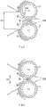
In hydroelectric installation 1 of the present invention, as mentioned above, can adjust with movable gate 5,5 opening area of damping hole.According to the principle of damping hole, if the opening area of this damping hole diminishes, lead to the discharge reduction of vertical pivot water turbine 3,3, its result, the rotating force of vertical pivot water turbine 3,3 seems to decline, but really not so in the present invention.Based on Fig. 6, its principle is described.
Fig. 6 is for the ideograph of the damping hole of hydroelectric installation 1 and the relation of vertical pivot water turbine 3,3 is described.Fig. 6 (a) represents that the opening area of damping hole is A1, and Fig. 6 (b) represents the situation that the opening area of damping hole is A2.
In the state of Fig. 6 (a), lead to the water of vertical pivot water turbine 3,3 by the opening portion of the opening area A1 of damping hole.In the current that pass through at this, the rotation blade that current a is directed to the center between two vertical pivot water turbine 3,3 is the rotation blade 33a recording in Fig. 6 (a).In addition, the rotation blade that the rotation of two vertical pivot water turbine 3,3 is played to maximum effect is the rotation blade 33b in Fig. 6 (a).In other words, the rotating force of left and right vertical pivot water turbine 3,3 be directly with the flow of the water of the front end collision of this rotation blade 33b.
With respect to this, at the state of Fig. 6 (b), even if also movable gate 5,5 moves and while making the opening area of damping hole be the A2 that is less than A1, current are by the opening portion of this opening area A2 to closing direction.In this case, although the opening area of damping hole diminishes, the water yield that directly flows to the front end of rotation blade 33b does not almost change.So, in hydroelectric installation 1 of the present invention, even if the opening area of damping hole diminishes, also can make it can not produce considerable influence to the rotating force of vertical pivot water turbine 3,3.Thus, on one side can adjust the water level of upstream side, Yi Bian carry out stable hydroelectric power, about its reason, below with reference to Fig. 7~Figure 15, describe.
Except Fig. 7~Figure 15 of Figure 10 is the simplified pattern of Fig. 2.The water that accumulates upstream side by water collecting board 6, the water level that represents the upstream side that this accumulates and flow from damping hole circulation and the relation of flow velocity.
When exemplifying Fig. 7 and describing, if the flow from upstream is designated as, Q1, effectively water-head is designated as H1, the flow velocity of the current of discharging from damping hole is designated as V1, damping hole opening area are designated as A1, gravity accleration is designated as g, and flow velocity V1 can represent by following formula.
It should be noted that,, do not consider the section shrinkage that vena contracta causes here.
Suppose, the flow of discharging from damping hole is flow Q1, and this flow Q1 is expressed from the next.
Therefore, as shown in Figure 7, when the discharge flow rate of the flow from upstream and damping hole is Q1, by adjusting the opening area of damping hole, can adjust effective water level.
In addition, when the flow from upstream changes, by adjusting the opening area of damping hole, can make effective water-head keep certain.
Thereby, in the hydroelectric power on water channel, importantly, when making every effort to maximum generation, need to make from the flow of upstream identical with the discharge flow rate of damping hole.For example, as shown in Figure 8, while supposing that flow Q1, Q3 from upstream is less than flow Q2, the Q4 that damping hole discharges, effectively water-head H1, H2 reduce.In addition, if a side of Q1, Q3 is many, effectively water-head H1, H2 increase.
With regard to water channel, the example of the water yield that annual maintenance is certain is less, and especially agricultural water changes approximately 2~5 times conventionally in the water yield of during irrigation period, non-during irrigation period.And the flow velocity V of the current that the variation of this water yield is discharged damping hole and effectively water-head H exert an influence.
With reference to Fig. 9 explanation from the variation of the flow of upstream to flow velocity V and effectively water-head H variation, also have the dependency relation of the variation of generated energy W=QgH.
Conventionally, generated energy W1 is W1=Q5 * g * H3.In addition, if reduced from the flow of upstream, and the opening area of damping hole cannot adjust, and can cause H4 and V4 to reduce.
Here, the water level about general water channel describes with reference to Figure 10.Water channel function is originally to determine water channel section configuration and the water channel gradient for the plan water yield.Generally speaking, set object and the condition of the water channel of planning, design meets the water channel section of this condition.Meet the plan flow (maximum, minimum) of designed object water channel, the depth of water Hc of this plan water yield (maximum value).Generally speaking, eighty per cant depth of water that Hb is Ha.It determines water channel section, the water channel gradient according to the Man Ningshi of hydraulic calculation formula and Al Kut formula.Now, the flow velocity of water channel is set as mean velocity 1.2m/sec~1.5m/sec left and right conventionally.Meanwhile, as general knowledge, this current velocity should be designed to become more and more faster along with flowing to downstream.Maintain this water channel function and and power plant for emergency will become the important necessary condition of water channel generating.
The meaning of its expression is described with reference to Figure 11.This Figure 11 take the mode of patterned represent when by the flow from upstream as Qa, the upper pool elevation opening area that is Ha, damping hole is during as A, effectively water-head is that H, flow velocity are that the discharge flow rate of V, damping hole is Qb.Ha as upper pool elevation is the override item that maintains its water channel function.This water level can not surpass maximum allow depth of water Hb, and while making as required generated energy increase, need to improve the volume of head race.
Then, with reference to Figure 12, hydroelectric installation state when the water yield increases and reduce when not adjusting the opening area of damping hole is described.When the water yield increases, although upper pool elevation becomes He, surpass flow+Qc overflow water collecting board 6 of Hb, can not be used to generating.Upper pool elevation He when therefore, the water yield increases can not surpass Hb.In addition, when discharge reduction, upper pool elevation He can reduce, and the effective water-head H of its result also can reduce.Therefore, because this dual minimizing of the minimizing of the minimizing of Qa and H, cause reducing the generating efficiency of hydroelectric installation, thereby in reducing the unfavoured state of the whole amount of generated energy itself.
With reference to Figure 13 and Figure 14 explanation, when this discharge reduction and the water yield increase, hydroelectric installation of the present invention can change upper waters bit position by adjusting the opening area of damping hole.First, as shown in figure 13, when discharge reduction, when the opening area of damping hole is altered to A2 from A1, theoretical generated energy is respectively W1=Qa * g * H1, W2=Qa * g * H2, obtains in the nature of things the generated energy of W1 < W2., why can access the generated energy of W2 here, be because the opening area of damping hole can be altered to A2 from A1.That is, in the case, in order to make the water surface rise to the water level that can maintain water channel function, the discharge flow rate of damping hole is reduced.That is, can make movable gate 5 move to closing direction, to reduce the opening area of damping hole.So long as can keep the opening area A2 of the damping hole of H2, can obtain the generated energy of W2.
Similarly, if the opening area of damping hole can be expanded so that the water yield while increasing the flow+Qc of overflow be used to generating, can improve generated energy.In the case, as long as the discharge flow rate of damping hole is increased, with reach the flow+Qc that makes overflow can the water level of overflow on.That is, as long as movable gate 5 is moved to opening direction, so that the opening area of damping hole becomes large.Generated energy is now W3=Qa * g * H3, W4=(Qa+Qc) * g * H4.While so arranging, can not cause the overflow of upper pool elevation, and then can improve maximum generating watt.
So, in hydroelectric installation of the present invention, can adjust by opening and closing movable gate the opening area of damping hole, therefore can not reduce hydroelectric efficiency, can realize increase and the performance flow of generated energy and adjust function.In addition, can stop the water that flows to vertical pivot water turbine by closing movable gate completely, therefore can easily carry out maintenance operation.
It should be noted that, sometimes exist because the amount of surging is many, only by expanding the opening area of damping hole, cannot prevent the situation of overflow.In this case, as shown in figure 15, can also adopt at water collecting board 6 water collecting board flow adjustment opening portion is set, by this opening portion, the water of overflow is discharged into the form in downstream side.And, also can be configured at water collecting board 6 and arrange and open and close door leaf (omitting diagram), according to the SEA LEVEL VARIATION of water channel, regulate the opening degree that opens and closes door leaf, thereby make the overflow water of the upstream side of water channel by stream, not be discharged into downstream side.
In above-mentioned hydroelectric installation 1, adopt the vertical pivot water turbine 3,3 of twin shaft, but also can adopt the vertical pivot water turbine 3 of the single shaft of structure as shown in figure 16.In this Figure 16, be shown in respectively open mode and the closed condition of movable gate 5 in the hydroelectric installation 1 of the vertical pivot water turbine 3 that has adopted single shaft, for the identical function of the structure with described hydroelectric installation 1, member, give identical symbol.At this, about structure, action, almost identical with described hydroelectric installation 1, so detailed.
The opening-closing structure of movable gate 5 is not limited thereto, and example as shown in figure 17, can be also the structure in downstream side by gear arrangement.
In this hydroelectric installation 1, movable gate 5 is different from aforementioned embodiments, and the upper plate 55 of main body 51 forms semi-circular shape, at it, forms profile of tooth around.And as shown in Figure 17 (a), a part for this upper plate 55 is combined with main body.The parts of tooth of upper plate 55 and gear 54 engagements, if swing pinion 54, upper plate 55 is linked and is rotated, identical with aforementioned embodiments, movable gate 5 is opened and closed.
As the method for swing pinion 54, use in the present embodiment handle 57.That is, the front end of the chimeric handle 57 in upper end by the rotating shaft 56 at gear 54, thus by the grasping part 58 to handle 57, be rotated operation, can make gear 54 rotations.
At this, the present invention is not limited to above-mentioned mode of execution, in not changing the scope of invention aim, can consider following various mode of execution.
For example, be adapted to arrange the situation of the water channel of hydroelectric installation 1, can change the form of water collecting board 6.As shown in figure 18, in the time of on the water channel that this hydroelectric installation 1 is arranged on to wider width, with retaining element 61, the two end part of water collecting board 6 are fixed on two walls of water channel.In this case, water collecting board 6 is not only as blocking the unit that the flowing water on water channel accumulates, can also be as shell 2 is connected, be fixed to the unit on water channel and act on.
With respect to this, as shown in figure 19, when this hydroelectric installation 1 is arranged on the narrower water channel of width, the two end part of shell 2 are directly fixed on two walls of water channel with retaining element 61.Now, the front panel 27 of shell 2 has concurrently as the function of fixed unit with as the function of water collecting board 6.
And, as shown in figure 20, when being arranged on while not having on ladder is poor and width is narrower water channel, Yi Bian water collecting board 6 block the flowing water on water channel and accumulate, Yi Bian make the water level of upstream side rise and make drop in water channel.Thus, can bring into play the function that the potential energy that utilizes drop and produce is acted on to the vertical pivot water turbine 3 in shell 2.
And, on the water channel with the poor and wider width of ladder shown in Figure 21, if shell 2 is set in the downstream side of the poor part of ladder, utilize the drop of the water of wandering the poor part of ladder, can be by larger energy on vertical pivot water turbine 3.
In addition, in the time of on being arranged on the wider water channel of width, as shown in figure 22, in the poor part of the ladder of water channel, water tank 62 is set, at the intake 62a of this water tank 62, water collecting board 6 is installed, the shell 2 of hydroelectric installation 1 is installed at drain opening 62b.Now, water collecting board 6 can be used as the water collecting board 6A towards the direction of the flow direction perpendicular to water channel, or as the water collecting board 6B towards the direction that flows to predetermined oblique angle with water channel.Thus, water collecting board 6 not only plays and makes the water level of upstream side increase and the effect of making drop, also plays the effect that the water in upstream flow is focused on to central water tank 62.
And, although in hydroelectric installation 1 of the present invention, be not necessary formation, as additional function, can be as follows, make speeding up plate 7 there is discharge function.
That is, in hydroelectric installation 1 shown in Figure 23, speeding up plate 7 consists of lifting type sluice, offers the discharge orifice 28,28 that allows water connect on the side plate 23,23 of shell 2 both sides.Thus, as shown in the figure, closing under the state of movable gate 5,5, by the vertical direction, promote speeding up plate 7,7, can make the water of stream 25 inside to the outside of shell 2, discharge by discharge orifice 28 from the gap between speeding up plate and base plate 22.Therefore, even hydroelectric installation 1 is arranged in water channel, also need not stop the current of water channel, can carry out the maintenance work to parts such as the vertical pivot water turbine 3 of shell 2 inside or generators 4.
And, as the variation of speeding up plate 7, can adopt the form shown in Figure 24.This speeding up plate 7 is for having the rotary gate of rotary switching door leaf 71, in the central authorities of speeding up plate 7, is provided with and opens and closes door leaf 71, and this switchings door leaf 71 is supported for centered by pivotal axis 72, can rotate along the direction of arrow in figure.When being configured to this structure, to close under the state of movable gate 5,5, the state as long as the switching door leaf 71 of speeding up plate 7 is rotated in opening, can be discharged into the outside of shell 2 by the water of stream 25 inside from discharge orifice 28.At this, the form with the speeding up plate 7 of discharge function is not limited thereto, and also can adopt the sliding gate (omitting diagram) of single evolution formula that can open and close in the horizontal direction or two evolution formulas.
Symbol description:
1 hydroelectric installation
2 shells
21 upper plates
22 base plates
23 side plates
24 sliding-grooves
25 streams
26 bearings
27 front panels
28 discharge orifices
3 vertical pivot water turbine
31 rotating shafts
32 pulleys
33 rotation blades
4 generators
41 live axles
42 pulleys
43 take turns band
5 movable gates
51 main bodys
52 toothed region
53 bearings
54 gears
55 upper plates
56 rotating shafts
57 handles
58 grasping parts
6 water collecting boards
61 retaining elements
62 water tanks
7 speeding up plate
71 open and close door leaf
72 pivotal axis
8 water inlets
9 drain opening
A damping hole (water flowing sectional area)
Claims (6)
1. a hydroelectric installation, is arranged on mobile water channel and generates electricity, and it is characterized in that, comprises:
Shell, its have the upstream side that is configured in described water channel water inlet, be configured in the drain opening in downstream side and the stream that is communicated to drain opening from water inlet;
Water collecting board, it is arranged on the edge of opening of the water inlet of described shell, and the flowing water on described water channel is blocked and accumulated and catchment to described water inlet;
Vertical pivot water turbine, it has the rotation blade rotatably being supported in the stream of described shell;
Generator, it is subject to the rotating force of described vertical pivot water turbine and generates electricity;
Movable gate, it is flowed into and acts on the water flowing sectional area of current of the rotation blade front end of described vertical pivot water turbine from described water inlet by increase and decrease, and capable of regulating accumulates in the water level of water of the upstream side of described water channel.
2. hydroelectric installation according to claim 1, it is characterized in that, described movable gate is configured to, in the direction perpendicular to described stream, open and close and the structure of increase and decrease water flowing sectional area, or be installed in the rotating shaft of described vertical pivot water turbine, by the periphery along described rotation blade, open and close the structure that increases and decreases water flowing sectional area.
3. hydroelectric installation according to claim 1 and 2, is characterized in that, is provided with and is arranged in described shell, and the opening area that makes described water inlet reduces gradually and makes the speeding up plate of the current speedup in described stream.
4. hydroelectric installation according to claim 3, it is characterized in that, described speeding up plate is configured to the sluice that can vertically promote, the sliding gate can along continuous straight runs opening and closing or rotatable rotary gate centered by pivotal axis, by opening this gate, the water in described stream is discharged into housing exterior from the discharge orifice being arranged on described shell.
5. hydroelectric installation according to claim 1, is characterized in that being configured to switching door leaf is set on described water collecting board, by opening this switching door leaf, makes the overflow water of the upstream side of described water channel by described stream, not be discharged into downstream side.
6. hydroelectric installation according to claim 1, is characterized in that, described vertical pivot water turbine is the crossflow turbine of single shaft or opposed twin shaft.
Applications Claiming Priority (3)
| Application Number | Priority Date | Filing Date | Title |
|---|---|---|---|
| JP2011111809A JP4817471B1 (en) | 2011-05-18 | 2011-05-18 | Hydroelectric generator |
| JP2011-111809 | 2011-05-18 | ||
| PCT/JP2011/069889 WO2012157131A1 (en) | 2011-05-18 | 2011-09-01 | Hydroelectric generator device |
Publications (2)
| Publication Number | Publication Date |
|---|---|
| CN102959232A CN102959232A (en) | 2013-03-06 |
| CN102959232B true CN102959232B (en) | 2014-01-22 |
Family
ID=45327032
Family Applications (1)
| Application Number | Title | Priority Date | Filing Date |
|---|---|---|---|
| CN201180002871.1A Expired - Fee Related CN102959232B (en) | 2011-05-18 | 2011-09-01 | Hydroelectric generator device |
Country Status (15)
| Country | Link |
|---|---|
| EP (1) | EP2711541B1 (en) |
| JP (1) | JP4817471B1 (en) |
| CN (1) | CN102959232B (en) |
| AP (1) | AP2013007296A0 (en) |
| BR (1) | BR112012007068A2 (en) |
| ES (1) | ES2560434T3 (en) |
| IN (1) | IN2012DN02560A (en) |
| MX (1) | MX2012003965A (en) |
| MY (1) | MY168230A (en) |
| PE (1) | PE20130471A1 (en) |
| PL (1) | PL2711541T3 (en) |
| RU (1) | RU2500916C1 (en) |
| SI (1) | SI2711541T1 (en) |
| TW (1) | TWI472679B (en) |
| WO (1) | WO2012157131A1 (en) |
Families Citing this family (38)
| Publication number | Priority date | Publication date | Assignee | Title |
|---|---|---|---|---|
| JP2000031142A (en) * | 1998-07-16 | 2000-01-28 | Fujitsu Ltd | Semiconductor device and production thereof |
| CN103573529B (en) * | 2012-08-01 | 2017-06-13 | 杭州林黄丁新能源研究院有限公司 | The hydraulic turbine |
| WO2014019266A1 (en) * | 2012-08-01 | 2014-02-06 | Lin Dong | Vertical ocean energy collection and power generation apparatus |
| CN102900589A (en) * | 2012-10-29 | 2013-01-30 | 梁孟林 | Turning wheel hydroelectric generation system |
| JP6090714B2 (en) * | 2013-02-14 | 2017-03-08 | 浩平 速水 | Power generation system |
| JP5919596B2 (en) * | 2013-03-11 | 2016-05-18 | 株式会社中山鉄工所 | Hydroelectric generator |
| JP5600789B1 (en) * | 2013-03-29 | 2014-10-01 | 中央電子システム株式会社 | High-efficiency output-stabilized power generator and flowing water type small hydropower system |
| WO2014157719A1 (en) * | 2013-03-29 | 2014-10-02 | 中央電子システム株式会社 | High-efficiency output stabilization power generation device and small water-flow type hydraulic power generation system |
| JP2014227986A (en) * | 2013-05-27 | 2014-12-08 | 英一 猪坂 | Hydroelectric power generation device |
| JP2014231777A (en) * | 2013-05-29 | 2014-12-11 | 株式会社中山鉄工所 | Hydraulic power generation device |
| JP6631825B2 (en) * | 2013-05-31 | 2020-01-15 | 浩平 速水 | Power generation system |
| CN104343619B (en) * | 2013-08-06 | 2017-05-10 | 杭州林黄丁新能源研究院有限公司 | Water flow adjusting device and ocean energy power generation device using water flow adjusting device |
| CN104763582B (en) * | 2014-01-03 | 2018-01-02 | 杭州林东新能源科技股份有限公司 | Rolling door type weight adjustment device and its ocean power generating device of application |
| JP2015140662A (en) * | 2014-01-27 | 2015-08-03 | 倫文 木原 | Hydraulic generating apparatus |
| KR101653373B1 (en) * | 2014-07-21 | 2016-09-01 | 한국해양과학기술원 | Dual turbine assembly for low-head hydropower generation |
| CN105525672A (en) * | 2015-01-16 | 2016-04-27 | 厦门市政工程公司 | Energy collection device on drop well part |
| CN104976024A (en) * | 2015-04-17 | 2015-10-14 | 李德生 | Water power shunt water diversion rotary blade power generation system |
| CN104976025A (en) * | 2015-04-17 | 2015-10-14 | 李德生 | Double water energy diversion plowshare rotary vane power generation system |
| CN104989581A (en) * | 2015-04-17 | 2015-10-21 | 李德生 | Beveled rotary blade diverting hydroelectric generator |
| CN104976028A (en) * | 2015-04-17 | 2015-10-14 | 李德生 | Double-hydraulic energy flow dividing rotary vane power generation system |
| CN105003380A (en) * | 2015-04-17 | 2015-10-28 | 李德生 | Dual-water-energy flow-dividing water-guiding rotary vane power generation system |
| NO340092B1 (en) * | 2015-06-01 | 2017-03-06 | Deep River As | Drop and Go Turbine |
| RU2619969C1 (en) * | 2015-12-22 | 2017-05-22 | Анистрад Григорьевич Васильев | All-season micro run-of-river plant |
| CN105781856B (en) * | 2016-05-04 | 2018-01-02 | 旺苍县科美防震科技有限公司 | A kind of floatable river course hydropower station |
| CN105971806B (en) * | 2016-06-30 | 2018-08-07 | 邓路坪 | A kind of quantitative hydraulic hydraulic turbine |
| TWI624589B (en) | 2016-07-21 | 2018-05-21 | Lai Rong Yi | Low head large flow channel turbine |
| CN106837663B (en) * | 2017-02-25 | 2018-10-26 | 郭保田 | Rivers low water level power generator |
| RU2688623C2 (en) * | 2017-10-23 | 2019-05-21 | Виктор Иванович Волкович | Water-wind engine |
| KR101922237B1 (en) * | 2018-06-26 | 2019-02-13 | 주식회사 오성기계 | Moving and semi-submerged generators using an aberration turbine |
| KR102095038B1 (en) * | 2018-08-08 | 2020-03-30 | 공대원 | Underwater power generator |
| JP2020051267A (en) * | 2018-09-25 | 2020-04-02 | Ntn株式会社 | Hydraulic power generation device |
| JP7206916B2 (en) * | 2019-01-04 | 2023-01-18 | 中国電力株式会社 | Overflow control device and overflow control method |
| CN110258462A (en) * | 2019-06-08 | 2019-09-20 | 宁波西沃工程科技有限公司 | A kind of hydraulic engineering gate flow velocity regulation device |
| CN110777741A (en) * | 2019-10-18 | 2020-02-11 | 河海大学 | Compromise sluice of electricity generation |
| TWI718916B (en) * | 2020-03-30 | 2021-02-11 | 賴融毅 | Device for adjusting water flow and water turbine using the same |
| AU2021103779A4 (en) * | 2020-11-10 | 2021-08-19 | Scott Hookey | A modular electricity generation system |
| WO2023163252A1 (en) * | 2022-02-25 | 2023-08-31 | 주식회사 씨앤에이에너지 | Hydroelectric power generation apparatus |
| TWI817671B (en) * | 2022-08-24 | 2023-10-01 | 崑山科技大學 | A water turbine system and a water turbine with high efficiency and low noise |
Citations (2)
| Publication number | Priority date | Publication date | Assignee | Title |
|---|---|---|---|---|
| JPS56138466A (en) * | 1980-03-31 | 1981-10-29 | Minoru Yoshimura | Fluid energy converter |
| JP2010031791A (en) * | 2008-07-30 | 2010-02-12 | Michihiro Oe | Hydro-electric generating device |
Family Cites Families (13)
| Publication number | Priority date | Publication date | Assignee | Title |
|---|---|---|---|---|
| US326718A (en) * | 1885-09-22 | collins | ||
| US1326769A (en) * | 1919-12-30 | Lockhart mithn | ||
| US1487391A (en) * | 1921-03-31 | 1924-03-18 | Firm Of Locher & Company | Hydraulic power plant |
| US4998846A (en) * | 1989-01-26 | 1991-03-12 | Evstratov Jury I | Concrete dam bottom discharge works |
| JPH0465965A (en) * | 1990-07-02 | 1992-03-02 | Ricoh Co Ltd | Image reader |
| JPH0465965U (en) * | 1990-10-08 | 1992-06-09 | ||
| RU2131993C1 (en) * | 1997-08-08 | 1999-06-20 | Антонюк Олег Борисович | Damless river-channel hydroelectric power plant |
| JP2001153021A (en) * | 1999-11-29 | 2001-06-05 | Tone Corp | Hydraulic power generating equipment for low head |
| RU2360141C1 (en) * | 2007-10-04 | 2009-06-27 | ФГОУ ВПО Московский государственный университет природообустройства (МГУП) | Motor for fluid energy utilisation |
| JP4705086B2 (en) * | 2007-11-06 | 2011-06-22 | 通博 大江 | Hydroelectric generator |
| JP4134277B2 (en) * | 2008-03-31 | 2008-08-20 | シーベルインターナショナル株式会社 | Small head hydroelectric generator |
| JP2010031797A (en) * | 2008-07-30 | 2010-02-12 | Toyota Motor Corp | Exhaust emission control device of internal combustion engine |
| DE202010010649U1 (en) * | 2009-08-08 | 2010-10-21 | Thümmler, Kurt | Stationary river hydropower plant with submerged water wheel |
-
2011
- 2011-05-18 JP JP2011111809A patent/JP4817471B1/en active Active
- 2011-09-01 EP EP11815430.1A patent/EP2711541B1/en not_active Not-in-force
- 2011-09-01 PL PL11815430T patent/PL2711541T3/en unknown
- 2011-09-01 PE PE2012000416A patent/PE20130471A1/en active IP Right Grant
- 2011-09-01 SI SI201130718T patent/SI2711541T1/en unknown
- 2011-09-01 MX MX2012003965A patent/MX2012003965A/en active IP Right Grant
- 2011-09-01 AP AP2013007296A patent/AP2013007296A0/en unknown
- 2011-09-01 WO PCT/JP2011/069889 patent/WO2012157131A1/en active Application Filing
- 2011-09-01 MY MYPI2012001257A patent/MY168230A/en unknown
- 2011-09-01 BR BR112012007068A patent/BR112012007068A2/en not_active Application Discontinuation
- 2011-09-01 CN CN201180002871.1A patent/CN102959232B/en not_active Expired - Fee Related
- 2011-09-01 RU RU2012113641/06A patent/RU2500916C1/en not_active IP Right Cessation
- 2011-09-01 ES ES11815430.1T patent/ES2560434T3/en active Active
-
2012
- 2012-01-17 TW TW101101846A patent/TWI472679B/en active
- 2012-03-23 IN IN2560DEN2012 patent/IN2012DN02560A/en unknown
Patent Citations (2)
| Publication number | Priority date | Publication date | Assignee | Title |
|---|---|---|---|---|
| JPS56138466A (en) * | 1980-03-31 | 1981-10-29 | Minoru Yoshimura | Fluid energy converter |
| JP2010031791A (en) * | 2008-07-30 | 2010-02-12 | Michihiro Oe | Hydro-electric generating device |
Also Published As
| Publication number | Publication date |
|---|---|
| IN2012DN02560A (en) | 2015-08-28 |
| MX2012003965A (en) | 2013-01-10 |
| EP2711541A1 (en) | 2014-03-26 |
| BR112012007068A2 (en) | 2016-04-19 |
| RU2500916C1 (en) | 2013-12-10 |
| PE20130471A1 (en) | 2013-04-27 |
| WO2012157131A1 (en) | 2012-11-22 |
| SI2711541T1 (en) | 2016-02-29 |
| CN102959232A (en) | 2013-03-06 |
| TW201221761A (en) | 2012-06-01 |
| ES2560434T3 (en) | 2016-02-19 |
| EP2711541B1 (en) | 2015-11-04 |
| AP2013007296A0 (en) | 2013-12-31 |
| JP2012241602A (en) | 2012-12-10 |
| JP4817471B1 (en) | 2011-11-16 |
| MY168230A (en) | 2018-10-15 |
| EP2711541A4 (en) | 2014-03-26 |
| TWI472679B (en) | 2015-02-11 |
| PL2711541T3 (en) | 2016-04-29 |
Similar Documents
| Publication | Publication Date | Title |
|---|---|---|
| CN102959232B (en) | Hydroelectric generator device | |
| US8616830B2 (en) | Hydraulic power generating apparatus | |
| CA1170960A (en) | Tidal power plant | |
| TWI624589B (en) | Low head large flow channel turbine | |
| KR100843752B1 (en) | Small hydropower generating apparatus | |
| KR101200458B1 (en) | Hydraulic power generating apparatus | |
| US20180023537A1 (en) | Hydroelectric power generator using ebb and flow of seawater | |
| TW201643313A (en) | Simple hydroelectric generator | |
| KR101765188B1 (en) | Floodgate equipped with Hydro Power Generation | |
| JP2002256536A (en) | Automatic flow rate adjusting rotary gate used for channel | |
| CN108331705B (en) | A kind of tidal power generating device | |
| KR102206476B1 (en) | Tidal power plant | |
| CN111733772A (en) | River sluice for hydraulic engineering | |
| KR101493005B1 (en) | Flow energy harvesting apparatus by adjusting conditions of drainage pipe | |
| KR100284644B1 (en) | Low drop aberration | |
| CN114856895B (en) | Passive regulation type bidirectional tidal current energy power generation device | |
| RU2256092C2 (en) | Hydraulic unit for converting kinetic energy of water flow into electric energy | |
| JP2011157872A (en) | Transportable hydraulic power generating device | |
| RU2653647C1 (en) | Method of the jet hydro turbines power regulation | |
| JP2015140662A (en) | Hydraulic generating apparatus | |
| WO2022018046A1 (en) | Hydraulic power plant | |
| JPH1130179A (en) | Water turbine provided with weir board and hydraulic power plant | |
| SI22684A (en) | Mechanism for water inflow regulation in turbine | |
| JP2013032766A (en) | Hydraulic power unit | |
| JP2016514805A (en) | Watermill device and power generation method using the device |
Legal Events
| Date | Code | Title | Description |
|---|---|---|---|
| C06 | Publication | ||
| PB01 | Publication | ||
| C10 | Entry into substantive examination | ||
| SE01 | Entry into force of request for substantive examination | ||
| ASS | Succession or assignment of patent right |
Owner name: SEABELL INTERNAT CO., LTD. Free format text: FORMER OWNER: UNNO YUJI Effective date: 20130807 |
|
| C41 | Transfer of patent application or patent right or utility model | ||
| TA01 | Transfer of patent application right |
Effective date of registration: 20130807 Address after: Tokyo, Japan Applicant after: SEABELL INTERNATIONAL CO.,LTD. Address before: Tokyo, Japan Applicant before: Unno Yuji |
|
| C14 | Grant of patent or utility model | ||
| GR01 | Patent grant | ||
| CF01 | Termination of patent right due to non-payment of annual fee | ||
| CF01 | Termination of patent right due to non-payment of annual fee |
Granted publication date: 20140122 |