CN102946293A - DS (data strobe) encoding based parallel reception method and device thereof - Google Patents
DS (data strobe) encoding based parallel reception method and device thereof Download PDFInfo
- Publication number
- CN102946293A CN102946293A CN2012103629834A CN201210362983A CN102946293A CN 102946293 A CN102946293 A CN 102946293A CN 2012103629834 A CN2012103629834 A CN 2012103629834A CN 201210362983 A CN201210362983 A CN 201210362983A CN 102946293 A CN102946293 A CN 102946293A
- Authority
- CN
- China
- Prior art keywords
- data
- signal
- clock
- state
- parallel
- Prior art date
- Legal status (The legal status is an assumption and is not a legal conclusion. Google has not performed a legal analysis and makes no representation as to the accuracy of the status listed.)
- Granted
Links
Images


Landscapes
- Synchronisation In Digital Transmission Systems (AREA)
Abstract
The invention provides a DS encoding based parallel reception method and a parallel reception device. The method comprises the following steps: a data signal is restored to a clock signal through a clock restoring circuit; the data signal and the clock signal are synchronously sent into a serial/parallel data converter to output the N-bit data signal and a 1-bit data effective index signal; the signals are synchronized by a three-level register of a system work clock of a receiving device to finish proper data interaction in the asynchronous clock domains; and the synchronized data signal and the data effective index signal are synchronously sent into a parallel data receiver to perform data decoding reception. A simple logic circuit is used to realize reception of the high-speed transmission data by a low-speed system clock without increase of system phase-locked loop; the complexity of the design is reduced; the complexity of the technology is lowered; the yield is improved; and the communication rate is improved by using the low speed clock to receive the high-speed data.
Description
Technical field
The present invention relates to a kind of parallel receive method based on the DS coding, realized 4 bit strings and data converter and 4 parallel-by-bit data sinks in a kind of Spacewire of being applied in Node Controller.
Background technology
Along with the development of space technology and AEROSPACE APPLICATION further deeply, onboard processing and the interaction capabilities of spacecraft proposed more and more higher requirement.Spacewire is a kind of bus standard that European Space Agency (ESA) releases in order to solve the demand, has high-performance, low-power consumption, the characteristics such as highly reliable, and oneself is in successfully being applied in a plurality of space tasks at present.Spacewire adopts Data-Strobe(DS) coding techniques, data are directly transmitted by the Data signal during transmission, and the Strobe signal changed when every adjacent two Data signals were identical.The clock signal that Data signal and Strobe signal phase XOR obtain during reception is as the clock of reception of data signal.Adopt after the DS coding, two kinds of mainstream solutions of decoder: a kind of is that to adopt the traditional method of sampling meet sampling thheorem be high frequency clock signal sampling low-frequency data signal, but the clock that needs a high frequency, generally be to provide by phase-locked loop, increase the resource increase design complexities that the clock phase-locked loop resource can increase system; Another is by the clock recovery technology.What generally adopt at present is the clock recovery technology.This technology of sampling must face two problems, and one is data mutual integrity problems in asynchronous clock domain, and another is that data are become decoding problem after the parallel data.
Summary of the invention
In order to overcome the deficiency of clock recovery technology mutual integrity problem in asynchronous clock domain, the invention provides a kind of parallel receive method based on the DS coding, do not increase in system in the situation of clock phase-locked loop resource, receive the transmission data of high frequency with the system clock of low frequency.
The technical solution adopted for the present invention to solve the technical problems may further comprise the steps:
1) with a Data-Strobe(DS) Data signal in the code stream and Strobe signal XOR generated clock signal mutually, this clock signal is as the clock of sampled data signal;
The rising edge of the clock signal that 2) generates with the DS XOR is sampled to data-signal, and every sampling N position is one group of data; Trailing edge with clock signal is sampled to data-signal, and every sampling N position is one group of data; Do the sampling sign with the counter of a mould N; Be to determine that according to the form of data command coding N is several for packet, for the decoder of Spacewire Node Controller, the control character of minimum is 4, so the deserializer among the present invention is 4;
3) data of rising edge sampling and trailing edge sampling are stored according to sequencing position and bit interleaving, store the rear one group of data that is take the 2N position; By above-mentioned modulo-N counter the data of this 2N position are divided into one group of every N position;
4) the N bit data that will alternately store rear decomposition is undertaken three grades synchronously by system works clock and three grades of registers of receiving system, eliminates the metastable state of exchanges data in the asynchronous clock domain;
5) when described counter non-zero, generate a data effective index signal;
6) this data effective index signal is carried out three grades synchronously by receiving system system works clock through three grades of registers;
7) data-signal after synchronous and data effective index signal are carried out parallel data decoding reception, realize by a state machine.
First state of state machine is Detect_CtrlChar, rear initial condition namely resets, if 4 bit data that receive be control character (ESC, FCT, EOP or EEP) then, still remain on this state, other situations jump to NextState CargoBit4;
Second state of state machine is CargoBit4: the expression node has received 4 character bits; If 1. when previous state CargoBit10, detect data character under this state, then do not do any operation, directly be transferred to CargoBit8, if detect data or timing code during 2. resting on this state, do not do any operation yet, directly be transferred to CargoBit8, if 3. detect control character, then rest on this state; Control character may be received, data and timing code can not be received; Can detect all characters;
CargoBit8: the expression node has been received 8 character bits; Under this state, 8 character bits receiving are front 8 of data character (or data division of timing code), thereby must receive data or timing code, can not receive control character; Detect data or control character (but do not know it is what control character because only detect control bit ' 1', lower with), can not detect timing code; Unconditional branch is to CargoBit2;
CargoBit2: the expression node is received 2 character bits; If 1. when previous state CargoBit8, detect data character under this state, then do not do any operation, directly be transferred to CargoBit6, if 2. detect control character (but not knowing it is what control character), then rest on this state, if 3. detect data or timing code, then be transferred to CargoBit6; If detect control character (but not knowing it is what control character), then what control character is not specifically done detection, directly receive; Can not receive data or timing code;
CargoBit6: the expression node is received 6 character bits; Under this state, must be that node has detected data or timing code, 6 character bits receiving be front 6 of data character (or data division of timing code); Do not do any operation, unconditional branch is to CargoBit10;
CargoBit10: expression has received 10 character bits; Under this state, data or timing code must be received, control character can not be received; Detect data or control character, can not detect timing code, NULL character (this state ESC_Observed must for ' 0 '); Unconditional branch is to CargoBit4.
Described N is any even number.
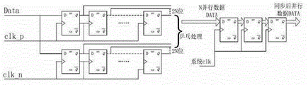
The present invention also provides a kind of device of realizing said method, comprise clock recovery circuitry, string and Date Conversion Unit and parallel data receiver, data-signal recovers clock signal through clock recovery circuitry, and data-signal and clock signal are sent into string and data converter simultaneously.The input signal of this string and data converter has Data signal, Strbdn signal, and the serial data that needs conversion is 1 Data signal.The output signal of this transducer is the data-signal of N position, and a data effective index signal.N bit data and a data effective index signal of output, it is correctly mutual to finish in the asynchronous clock domain data synchronously through three grades of registers of receiving system system works clock, the data-signal after synchronously and data effective index signal is sent into the parallel data receiver simultaneously carry out data decode and receive.
The invention has the beneficial effects as follows: the present invention has realized receiving the function that sends at a high speed data with the idling slow speed system clock with the simple logic circuit in the situation that does not increase system's phase-locked loop resource.Owing to do not increase the clock phase-locked loop resource, namely reduced system resource overhead, reduced the complexity of design, can reduce simultaneously the complexity of technique, improve rate of finished products.Adopt low-speed clock to realize receiving the data of higher rate, improved communication speed.
Description of drawings
Fig. 1 is the architecture block diagram that the present invention is based on the parallel receive technology of DS coding;
Fig. 2 is the DS clock recovery unit implementing circuit principle sketch among the present invention;
Fig. 3 is that DS recovered clock sampling serial data is to the realization schematic diagram of parallel data;
Fig. 4 is N bit string and translation data splicing schematic diagram;
Fig. 5 is that DS recovers just along clock sampling data time sequence figure;
Fig. 6 is for according to a N of the invention process being the sequential chart of 44 bit strings and conversion;
Fig. 7 is the present invention realizes 4 parallel-by-bit data sinks in the Spacewire Node Controller state diagram.
Embodiment
The invention provides a kind of parallel receive method based on the DS coding, the method is exactly that the data-signal that at first a DS code stream is transmitted is sampled by the clock signal that the DS signal recovers, and it is the parallel data of a N position that the serial data after the sampling is pieced together; Then this parallel data is processed synchronously through three grades, be sent to reliably the decoding of doing data receiver in the system clock territory; Be exactly at last in order to guarantee the promptness of data receiver, directly to the reception of decoding of this parallel data.
The parallel receive device based on the DS coding that the present invention realizes comprises: (1) serial-parallel conversion circuit that serial data bit stream is converted to a N position character stream, this circuit is not simply serial data to be become a parallel data by shift register, because the data that receive are not simple sequential data stream; The parallel data receiver of (2) N positions is at the parallel data receiver of the present invention according to one 4 of the character characteristics of SpaceWire agreement designs.In being applied in other system, N can be any even number, can expand to 2,4,8 etc.
1. go here and there and Date Conversion Unit
Before arriving this this unit, data-signal first through as shown in Figure 2 clock recovery circuitry, Data signal and DS clock are sent into this string and data dress parallel operation simultaneously.Key technology of the present invention is just at string and Date Conversion Unit, simply by the DS clock sampling to data directly deliver to decode in the receiver to receive and have data interaction problem in the asynchronous clock domain, be difficult to guarantee that data are complete, decoding is correct.This circuit can be realized N bit data string and conversion, and it is correctly mutual to finish synchronously in the asynchronous clock domain data through three grades.
Performing step:
1) data-signal is sampled with the rising edge of DS clock, does the sampling sign with the counter of a mould N, and the N position is one group;
2) data-signal is sampled with the trailing edge of DS clock, does the sampling sign with the counter of a mould N, and the N position is one group;
3) data of rising edge sampling and trailing edge sampling alternately deposit in the N bit register;
4) this N bit data is undertaken three grades synchronously by system clock;
5) counter of above-mentioned mould N generates a data effective index signal when non-zero;
6) this data useful signal is undertaken three grades synchronously by system clock;
7) data-signal after inciting somebody to action synchronously and data effective index signal are sent into simultaneously next parallel receive unit and are carried out the data decode reception.
2. parallel receive device unit
Parallel receive device unit, parallel data processor unit namely, the value of determining N is the key point of the design of receiver.N determines and will decide according to the characteristics of transmission character.If the highest order that parallel signal input in N road is analyzer can be allowed is wide, then adopt the clock of fMHz to decode
 The perhaps data of higher rate, but the highest data rate that can receive is no more than NfMbps.
The present invention is 4 road parallel receive devices of Spacewire Node Controller design, and the Spacewire agreement is formulated according to the 1355-1995 agreement, and provides on its basis Time-codes to be supported in the network layer broadcasting system time.The character that three types is arranged in the SpaceWire agreement, data character, control character and concatenation character.
Analyze SpaceWire character layer agreement character layer characteristic, wherein minimum character is 4, also is that the minimum bit wide of decoding is 4.So the highest order that the input of 4 road parallel signals is the Spacewire Rcv decoder can be allowed is wide.The 4 tunnel parallel data analysis of input sink analyzer to being recovered by the DS signal, each clock cycle can be processed 4 road parallel signals.
The present invention is further described below in conjunction with drawings and Examples.
As shown in Figure 2, from signal Data and the Strobd process XOR generation DS clock clkds of PAD, the rising edge of clk_p and the rising edge of clk_n are respectively rising edge and the trailing edges of clkds; Clk_p and two inputs of clk_n of generating, they all are clock signals asynchronous with system clock.If the rising edge clock that only produces with XOR is sampled to the Data signal, can only obtain half Data signal, so the clock signal that XOR produces will use rising edge and trailing edge is alternately sampled to the Data signal, can guarantee the integrality of data.Clock signal is sampled to the Data signal through after the gate, guarantees that by gate delay clock can correctly sample data.
The data-signal of input samples in the shift register that data deposit two 2N positions in by the positive clock clk_p that recovers and negative clock clk_n as shown in Figure 3.After receiving the 2N position, can deposit in the 2N bit register by system clock sample shift register intersection splicing data, behind system's clock synchronized sampling of 3 grades, clap output N parallel-by-bit data with 2.Wherein use the register of two 2N positions, do the table tennis processing and alternately send data.Namely owing to can't be correctly decoded the DS signal of fMbps with the clock of fMHz, the clock clkds that recovers with the DS signal is that the DS code signal of fMbps is divided into the signal that the two-way bit rate is f/2Mbps with bit rate.
As shown in Figure 4, only drawn the rising edge clkp of clkds among the figure to the sampling of D signal.Signal PEn is the two divided-frequency to clkds, as the enable signal of signal DataP, at rising edge and the trailing edge of PEn a valid data position is arranged.Synchronised clock is sampled to PEn, detect PEn along the time DataP sampled, obtain the valid data position, obtain half letter that former DS signal carries and deposit in the shift register of clk_p.The same method of second half information that the DS signal carries deposits in another shift register.Wherein two shift register data alternative splicings are deposited into register.
Fig. 6 is that a N is 4 string and conversion timing sequence figure, has wherein used the counter of a mould 4 and has controlled sampling and generate the enable signal of exporting data.
Parallel decoding analyzer primary structure is a state machine, and as shown in Figure 7, Detect_CtrlChar represents that node detects control character (ESC, FCT, EOP or EEP) under this state.CargoBit10: expression has received 10 character bits; Under this state, data or timing code must be received, control character can not be received; Detect data or control character, can not detect timing code, NULL character (this state ESC_Observed must for ' 0 '); Unconditional branch is to CargoBit4; CargoBit4: the expression node has received 4 character bits; If 1. when previous state CargoBit10, detect data character under this state, then do not do any operation, directly be transferred to CargoBit8, if detect data or timing code during 2. resting on this state, do not do any operation yet, directly be transferred to CargoBit8, if 3. detect control character, then rest on this state; Control character may be received, data and timing code can not be received; Can detect all characters; CargoBit8: the expression node has been received 8 character bits; Under this state, 8 character bits receiving are front 8 of data character (or data division of timing code), thereby must receive data or timing code, can not receive control character; Detect data or control character (but do not know it is what control character because only detect control bit ' 1 ', lower with), can not detect timing code; Unconditional branch is to CargoBit2; CargoBit2: the expression node is received 2 character bits; If 1. when previous state CargoBit8, detect data character under this state, then do not do any operation, directly be transferred to CargoBit6, if 2. detect control character (but not knowing it is what control character), then rest on this state, if 3. detect data or timing code, then be transferred to CargoBit6; If detect control character (but not knowing it is what control character), then what control character is not specifically done detection, directly receive; Can not receive data or timing code; CargoBit6: the expression node is received 6 character bits; Under this state, must be that node has detected data or timing code, 6 character bits receiving be front 6 of data character (or data division of timing code); Do not do any operation, unconditional branch is to CargoBit10.
Claims (5)
1. the parallel receive method based on the DS coding is characterized in that comprising the steps:
1) with the Data signal in the DS code stream and Strobe signal XOR generated clock signal mutually, this clock signal is as the clock of sampled data signal;
2) with the rising edge of clock signal data-signal is sampled, every sampling N position is one group of data; Trailing edge with clock signal is sampled to data-signal, and every sampling N position is one group of data; Do the sampling sign with the counter of a mould N;
3) data of rising edge sampling and trailing edge sampling are stored according to sequencing position and bit interleaving, store the rear one group of data that is take the 2N position; By above-mentioned modulo-N counter the data of this 2N position are divided into one group of every N position;
4) the N bit data that will alternately store rear decomposition is undertaken three grades synchronously by system works clock and three grades of registers of receiving system, eliminates the metastable state of exchanges data in the asynchronous clock domain;
5) when described counter non-zero, generate a data effective index signal;
6) this data effective index signal is carried out three grades synchronously by receiving system system works clock through three grades of registers;
7) data-signal after synchronous and data effective index signal are carried out parallel data decoding reception, realize by a state machine.
2. the parallel receive method based on DS coding according to claim 1, it is characterized in that: described N is any even number.
3. the parallel receive method based on DS coding according to claim 1, it is characterized in that: described N is 4.
4. the parallel receive method based on DS coding according to claim 1, it is characterized in that: first state of described state machine is Detect_CtrlChar, rear initial condition namely resets, if 4 bit data that receive are control characters, then still remain on this state, other situations jump to NextState CargoBit4;
CargoBit4: if when previous state CargoBit10, detect data character under this state, then do not do any operation, directly be transferred to CargoBit8; If detect data or timing code during resting on this state, do not do any operation yet, directly be transferred to CargoBit8; If detect control character, then rest on this state;
CargoBit8: detect data or control character under this state, unconditional branch is to CargoBit2;
CargoBit2: if when previous state CargoBit8, detect data character under this state, then do not do any operation, directly be transferred to CargoBit6; If detect control character, then rest on this state; If the data of detecting or timing code then are transferred to CargoBit6; If detect control character, then directly receive;
CargoBit6: do not do any operation under this state, unconditional branch is to CargoBit10;
CargoBit10: detect data or control character under this state, unconditional branch is to CargoBit4.
5. device of realizing the described parallel receive method based on DS coding of claim 1, comprise clock recovery circuitry, string and Date Conversion Unit and parallel data receiver, it is characterized in that: data-signal recovers clock signal through clock recovery circuitry, data-signal and clock signal are sent into string and data converter simultaneously, data-signal and a data effective index signal of output N position, it is correctly mutual to finish in the asynchronous clock domain data synchronously through three grades of registers of receiving system system works clock, the data-signal after synchronously and data effective index signal is sent into the parallel data receiver simultaneously carry out data decode and receive.
Priority Applications (1)
| Application Number | Priority Date | Filing Date | Title |
|---|---|---|---|
| CN201210362983.4A CN102946293B (en) | 2012-09-26 | 2012-09-26 | A kind of parallel receive method based on DS coding and device thereof |
Applications Claiming Priority (1)
| Application Number | Priority Date | Filing Date | Title |
|---|---|---|---|
| CN201210362983.4A CN102946293B (en) | 2012-09-26 | 2012-09-26 | A kind of parallel receive method based on DS coding and device thereof |
Publications (2)
| Publication Number | Publication Date |
|---|---|
| CN102946293A true CN102946293A (en) | 2013-02-27 |
| CN102946293B CN102946293B (en) | 2015-09-23 |
Family
ID=47729205
Family Applications (1)
| Application Number | Title | Priority Date | Filing Date |
|---|---|---|---|
| CN201210362983.4A Active CN102946293B (en) | 2012-09-26 | 2012-09-26 | A kind of parallel receive method based on DS coding and device thereof |
Country Status (1)
| Country | Link |
|---|---|
| CN (1) | CN102946293B (en) |
Cited By (3)
| Publication number | Priority date | Publication date | Assignee | Title |
|---|---|---|---|---|
| CN108073539A (en) * | 2017-12-27 | 2018-05-25 | 上海集成电路研发中心有限公司 | A kind of D-PHY circuits of MIPI interfaces |
| CN108462620A (en) * | 2018-02-11 | 2018-08-28 | 北京控制工程研究所 | A kind of Gb SpaceWire bus systems |
| CN113640654A (en) * | 2021-07-30 | 2021-11-12 | 四川芯测电子技术有限公司 | High-speed state analysis method and system |
Citations (2)
| Publication number | Priority date | Publication date | Assignee | Title |
|---|---|---|---|---|
| US6397312B1 (en) * | 1997-07-04 | 2002-05-28 | Fujitsu Limited | Memory subsystem operated in synchronism with a clock |
| CN101053232A (en) * | 2003-11-25 | 2007-10-10 | 高通股份有限公司 | High data rate interface with improved link synchronization |
-
2012
- 2012-09-26 CN CN201210362983.4A patent/CN102946293B/en active Active
Patent Citations (2)
| Publication number | Priority date | Publication date | Assignee | Title |
|---|---|---|---|---|
| US6397312B1 (en) * | 1997-07-04 | 2002-05-28 | Fujitsu Limited | Memory subsystem operated in synchronism with a clock |
| CN101053232A (en) * | 2003-11-25 | 2007-10-10 | 高通股份有限公司 | High data rate interface with improved link synchronization |
Non-Patent Citations (1)
| Title |
|---|
| 罗学平: "应用于航天器的高速数据传输技术的研究", 《中国会议》, 1 October 2006 (2006-10-01) * |
Cited By (5)
| Publication number | Priority date | Publication date | Assignee | Title |
|---|---|---|---|---|
| CN108073539A (en) * | 2017-12-27 | 2018-05-25 | 上海集成电路研发中心有限公司 | A kind of D-PHY circuits of MIPI interfaces |
| CN108462620A (en) * | 2018-02-11 | 2018-08-28 | 北京控制工程研究所 | A kind of Gb SpaceWire bus systems |
| CN108462620B (en) * | 2018-02-11 | 2020-10-20 | 北京控制工程研究所 | Gilbert-level SpaceWire bus system |
| CN113640654A (en) * | 2021-07-30 | 2021-11-12 | 四川芯测电子技术有限公司 | High-speed state analysis method and system |
| CN113640654B (en) * | 2021-07-30 | 2024-02-20 | 深圳速跃芯仪科技有限公司 | High-speed state analysis method and system |
Also Published As
| Publication number | Publication date |
|---|---|
| CN102946293B (en) | 2015-09-23 |
Similar Documents
| Publication | Publication Date | Title |
|---|---|---|
| Nowick et al. | Asynchronous design—Part 1: Overview and recent advances | |
| CN104954096B (en) | A kind of high-speed synchronous serial communication data transmission method of one master and multiple slaves | |
| JPH10117185A (en) | Synchronizer for data transfer, method and system | |
| CN103141066A (en) | Transmission circuit, reception circuit, transmission method, reception method, communication system and communication method therefor | |
| US10103830B2 (en) | Latency-optimized physical coding sublayer | |
| US9054941B2 (en) | Clock and data recovery using dual manchester encoded data streams | |
| US4694196A (en) | Clock recovery circuit | |
| WO2012083279A2 (en) | Low power serial to parallel converter | |
| CN102710240A (en) | Signal processing device and method, SERDES and processor | |
| CN102946293B (en) | A kind of parallel receive method based on DS coding and device thereof | |
| US8675798B1 (en) | Systems, circuits, and methods for phase inversion | |
| US10476630B2 (en) | Digital bus noise suppression | |
| CN204206158U (en) | A kind of clock data recovery circuit | |
| CN103078667A (en) | Low voltage differential signaling (LVDS) high-speed data transmission method based on cat-5 | |
| CN101039323B (en) | Multi-rate multi-protocol bit stream processor | |
| CN1161901C (en) | Up high-speed data synchronous receiving method and circuit in optical communication system | |
| CN105468561A (en) | High-speed asynchronous serial communication method | |
| CN101026448A (en) | Synchronous communication system clock regenerating method and system | |
| CN103279442A (en) | Message filtering system and message filtering method of high-speed interconnection bus | |
| CN102754407B (en) | Providing a feedback loop in a low latency serial interconnect architecture and communication system | |
| CN101577598A (en) | Multiple signal multiplexing and demultiplexing methods, devices and systems | |
| CN103067114A (en) | Transmission system asynchronous mapping clock recovery method and transmission system asynchronous mapping clock recovery device | |
| US6650696B1 (en) | System and method for communicating data among a plurality of digital signal processors | |
| CN204244256U (en) | A kind of multichannel E1 separates frame system | |
| CN100505765C (en) | Method of multi-channel data processing |
Legal Events
| Date | Code | Title | Description |
|---|---|---|---|
| C06 | Publication | ||
| PB01 | Publication | ||
| C10 | Entry into substantive examination | ||
| SE01 | Entry into force of request for substantive examination | ||
| C14 | Grant of patent or utility model | ||
| GR01 | Patent grant |