CN102555027A - Three-dimensional modeling device, three-dimensional modeling method, and model formed by the method - Google Patents
Three-dimensional modeling device, three-dimensional modeling method, and model formed by the method Download PDFInfo
- Publication number
- CN102555027A CN102555027A CN2011104175410A CN201110417541A CN102555027A CN 102555027 A CN102555027 A CN 102555027A CN 2011104175410 A CN2011104175410 A CN 2011104175410A CN 201110417541 A CN201110417541 A CN 201110417541A CN 102555027 A CN102555027 A CN 102555027A
- Authority
- CN
- China
- Prior art keywords
- shower nozzle
- objective table
- dusty material
- liquid
- shower
- Prior art date
- Legal status (The legal status is an assumption and is not a legal conclusion. Google has not performed a legal analysis and makes no representation as to the accuracy of the status listed.)
- Pending
Links
Images


Classifications
-
- B—PERFORMING OPERATIONS; TRANSPORTING
- B29—WORKING OF PLASTICS; WORKING OF SUBSTANCES IN A PLASTIC STATE IN GENERAL
- B29C—SHAPING OR JOINING OF PLASTICS; SHAPING OF MATERIAL IN A PLASTIC STATE, NOT OTHERWISE PROVIDED FOR; AFTER-TREATMENT OF THE SHAPED PRODUCTS, e.g. REPAIRING
- B29C64/00—Additive manufacturing, i.e. manufacturing of three-dimensional [3D] objects by additive deposition, additive agglomeration or additive layering, e.g. by 3D printing, stereolithography or selective laser sintering
- B29C64/10—Processes of additive manufacturing
- B29C64/165—Processes of additive manufacturing using a combination of solid and fluid materials, e.g. a powder selectively bound by a liquid binder, catalyst, inhibitor or energy absorber
-
- B—PERFORMING OPERATIONS; TRANSPORTING
- B33—ADDITIVE MANUFACTURING TECHNOLOGY
- B33Y—ADDITIVE MANUFACTURING, i.e. MANUFACTURING OF THREE-DIMENSIONAL [3-D] OBJECTS BY ADDITIVE DEPOSITION, ADDITIVE AGGLOMERATION OR ADDITIVE LAYERING, e.g. BY 3-D PRINTING, STEREOLITHOGRAPHY OR SELECTIVE LASER SINTERING
- B33Y10/00—Processes of additive manufacturing
-
- B—PERFORMING OPERATIONS; TRANSPORTING
- B33—ADDITIVE MANUFACTURING TECHNOLOGY
- B33Y—ADDITIVE MANUFACTURING, i.e. MANUFACTURING OF THREE-DIMENSIONAL [3-D] OBJECTS BY ADDITIVE DEPOSITION, ADDITIVE AGGLOMERATION OR ADDITIVE LAYERING, e.g. BY 3-D PRINTING, STEREOLITHOGRAPHY OR SELECTIVE LASER SINTERING
- B33Y30/00—Apparatus for additive manufacturing; Details thereof or accessories therefor
-
- Y—GENERAL TAGGING OF NEW TECHNOLOGICAL DEVELOPMENTS; GENERAL TAGGING OF CROSS-SECTIONAL TECHNOLOGIES SPANNING OVER SEVERAL SECTIONS OF THE IPC; TECHNICAL SUBJECTS COVERED BY FORMER USPC CROSS-REFERENCE ART COLLECTIONS [XRACs] AND DIGESTS
- Y10—TECHNICAL SUBJECTS COVERED BY FORMER USPC
- Y10T—TECHNICAL SUBJECTS COVERED BY FORMER US CLASSIFICATION
- Y10T428/00—Stock material or miscellaneous articles
- Y10T428/31504—Composite [nonstructural laminate]
- Y10T428/31855—Of addition polymer from unsaturated monomers
- Y10T428/31909—Next to second addition polymer from unsaturated monomers
Abstract
A three-dimensional modeling device, a three-dimensional modeling method, and a model formed by the method are disclosed. The three-dimensional modeling device includes: a stage having a powder material deposited thereon for lamination; a supply mechanism supplying the powder material for each one layer on the stage; a plurality of heads having a plurality of nozzles ejecting a liquid for formation of a model, respectively, and capable of ejecting the liquid to the powder material supplied onto the stage by the supply mechanism; and a moving mechanism moving the plurality of heads in different directions relative to the stage, respectively.
Description
Technical field
The disclosure relates to through three-dimensional moulding device and the 3-dimensional object formation that forms three-dimensional shape model based on cross sectional image data lamination and passes through the model that this method forms.
Background technology
In the past, this type of three-dimensional moulding device is regarded as so-called rapid molding device, and in commercial Application, is widely used.The main system of three-dimensional moulding device has: optics moulding system, thin plate lamination moulding system and powder moulding system.
The optics moulding system be through high power laser irradiates light cured resin form shape of cross section and lamination it, thereby create 3D shape.Thin plate lamination moulding system be in layer the excision thin plate and adhere to and lamination they to create 3D shape.The powder moulding system is to be used for scattering dusty material to form shape of cross section at layer, then lamination they to create 3D shape.
The powder moulding system further roughly is divided into those fusions or sintered powder and those use the curing powder of adhesive.The ink gun that The latter is used for printer etc. will be injected into the powder that gypsum is a main component such as the liquid of adhesive and adhesive, be used for solidifying and form cross-sectional layer and lamination they, thereby create 3D shape.
In the powder moulding that utilizes ink gun, for example use the printhead of commercially available ink-jet printer, just as printing, corresponding to the zone of wanting curing powder, will such as the liquid selective property of adhesive be ejected on the thin plate of powder distribution on it.Disclosing the three-dimensional moulding device of describing in 2009-101651 number in japanese unexamined patent is a kind of device (for example, disclosing 2009-101651 number with reference to japanese unexamined patent) that adopts powder moulding system ink gun.
Summary of the invention
In the styling apparatus that uses powder moulding system ink gun, if when being included in the part of a plurality of nozzles in the ink gun and taking place such as the injection defect situation stopped up, for example, the powder bed that comprises this defect area is by lamination.In other words, because with predetermined direction scanning ink-jet head, following serious problems have been caused: take place to spray producing linearity under the situation of defective in the formed model calmodulin binding domain CaM and model are not fragile in one direction at injection unit.
Expectation provides a kind of three-dimensional moulding device and 3-dimensional object formation, can be suppressed to form in the zone of component model to make model hold the zone of damaging and prevent model model impaired and that form through this method on frangible direction.
Three-dimensional moulding device according to embodiment of the present disclosure comprises: objective table, feed mechanism, a plurality of shower nozzle and travel mechanism.
Pile up dusty material with the lamination mode on the objective table.
Feed mechanism supplies to each layer dusty material on the objective table.
A plurality of shower nozzles have a plurality of nozzles that spray the liquid that is used to form model separately, and these a plurality of shower nozzles can be injected into liquid by feed mechanism and supply to the dusty material on the objective table.
Travel mechanism moves a plurality of shower nozzles respectively in different directions with respect to objective table.
Even occur spraying under the situation of defective at one of a plurality of nozzles of at least one shower nozzle, a plurality of shower nozzles move with respect to objective table through travel mechanism in different directions.Just, according to embodiment of the present disclosure, can suppress the formation of defect area, this defect area is possible the borderline region that model is fragile and concentrate in one direction that makes that takes place under the shower nozzle situation only is being set.Therefore, possibly prevent that on frangible direction model is impaired.
Also removable two shower nozzles as a plurality of shower nozzles of travel mechanism are so that these two shower nozzle moving direction quadratures.Than the situation of quadrature not, the moving direction quadrature of two shower nozzles can be simplified the structure of shower nozzle and travel mechanism.
Whenever feed mechanism supply one deck dusty material, travel mechanism also can alternately move a plurality of shower nozzles.Thereby, producing under the injection defect situation, the same position place that can be suppressed on the lamination dusty material direction forms defect area continuously.Alternately, also can be following embodiment.
When feed mechanism is supplied with the dusty material of the first continuous number of layers; First shower nozzle in the removable a plurality of shower nozzles of travel mechanism; And when feed mechanism is supplied with the dusty material of the second continuous number of layers, second shower nozzle different in the also removable a plurality of shower nozzles of travel mechanism with first shower nozzle.
In this case, first number of layers also can be different with second number of layers.For example, embodiment of the present disclosure is useful in following situation: under the situation that the liquid that each shower nozzle ejects has nothing in common with each other and the material supplied with of feed mechanism have nothing in common with each other for each shower nozzle.
Feed mechanism also can be supplied to objective table with the multiple different powder material that corresponds respectively to a plurality of shower nozzles.Alternatively, as stated, but each self-injection different liquid of a plurality of shower nozzle.These embodiments of the present disclosure can form for composition model every one or more layers and have the model of different qualities.
According to another embodiment of the present disclosure, three-dimensional moulding device comprises: objective table, feed mechanism, shower nozzle and travel mechanism.
Pile up dusty material with the lamination mode on the objective table.
Feed mechanism supplies to each layer dusty material on the objective table.
Shower nozzle has a plurality of nozzles that spray the liquid that is used to form model, and shower nozzle can be injected into liquid by feed mechanism and supply to the dusty material on the objective table.
When liquid was injected into the dusty material of the different layers of being supplied with by feed mechanism respectively, travel mechanism moved shower nozzle with respect to objective table on each different direction.
Even the situation of defective appears spraying in one of a plurality of nozzles that shower nozzle occurred being contained in, shower nozzle can move on different directions with respect to objective table through travel mechanism.Just, can suppress the formation of defect area and can prevent that model from damaging, wherein defect area is possibly make model frangible and concentrate on the direction what take place under the situation that a shower nozzle only is set.
In this case, three-dimensional moulding device can further comprise rotating mechanism, is used for about the axle rotary nozzle along the laminating direction of dusty material.Thereby, can change the moving direction of shower nozzle.
According to the 3-dimensional object formation of disclosure embodiment, comprise one deck dusty material is supplied to objective table.
With respect to objective table when first party moves up first shower nozzle, spray the liquid that is used to form model from first shower nozzle to the dusty material of supplying with on objective table.
Behind the first shower nozzle atomizing of liquids, another layer dusty material is supplied to objective table.
When the second party that is being different from first direction with respect to objective table moved up second shower nozzle, the dusty material of supplying with on objective table from the second shower nozzle item sprayed the liquid that is used to form model.
Model according to disclosure embodiment is the model that forms through above-mentioned 3-dimensional object formation.
As stated, according to embodiment of the present disclosure, can be suppressed to form in the zone of component model and make the zone that model damages easily and prevent that model is impaired on frangible direction.
Description of drawings
Fig. 1 shows the three-dimensional moulding device according to disclosure embodiment;
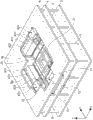
Fig. 2 shows the perspective view of internal structure of the main body case of three-dimensional moulding device;
Fig. 3 is the plane of the three-dimensional moulding device shown in Fig. 2;
Fig. 4 be intercepting from the side three-dimensional moulding device viewgraph of cross-section and show the state of the three-dimensional moulding device that top cover removes from main body case;
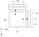
Fig. 5 A is the graphic plan view that X shower nozzle and Y shower nozzle are shown, and Fig. 5 B is its modified example;
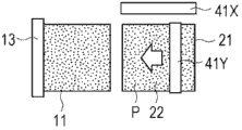
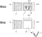
Fig. 6 A to Fig. 6 E shows the action of three-dimensional moulding device, and is the graphic plan view of main part that shows the three-dimensional moulding device of action in order;
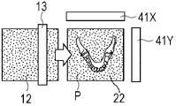
Fig. 7 A and Fig. 7 B show the plane of the molding flask that holds model therein, and this model is to form through the method with the contrast of this embodiment;
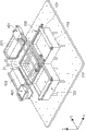
Fig. 8 shows the perspective view according to the main part of the three-dimensional moulding device of another embodiment of the disclosure;
Fig. 9 shows the three-dimensional moulding device shown in Fig. 8 and is in the perspective view that has removed top board and printing substrate state;
Figure 10 show according to the disclosure again the three-dimensional moulding device of an embodiment main part and be the plane that molding flask and shower nozzle are shown; And
Figure 11 shows according to the main part of the three-dimensional moulding device of the another embodiment of the disclosure and is the plane that molding flask and shower nozzle are shown.
The specific embodiment
Below will describe for embodiment of the present disclosure with reference to accompanying drawing.
[embodiment]
(configuration of three-dimensional moulding device)
Fig. 1 shows the three-dimensional moulding device according to disclosure embodiment.
Three-dimensional moulding device 100 is provided with main body case 1 that is about rectangular shape and the control circuit box 3 that is connected to main body case 1.Main body case 1 has side cover 5, is installed in the body cover 7 on the side cover 5, and the top cover 6 that can remove from body cover 7.
Fig. 2 shows the perspective view of internal structure of the main body case 1 of three-dimensional moulding device 100.Fig. 3 is the plane of the three-dimensional moulding device 100 shown in Fig. 2.Fig. 4 be intercepting from the side three-dimensional moulding device 100 viewgraph of cross-section and show the state of the three-dimensional moulding device 100 that top cover 6 removes from main body case 1.
Three-dimensional moulding device 100 has from the bottom successively: substrate 2, printing substrate 4 and top board 8, and they all pass through a plurality of column assemblies 9 and connect.Like Fig. 3 and shown in Figure 4, between substrate 2 and printing substrate 4, be provided with along the feed unit 10 and molding unit 20 of Y direction alignment.Molding unit 20 is disposed generally on the center of X and Y direction.
Feed unit 10 as feed mechanism supplies to molding unit 20 with dusty material P (being designated hereinafter simply as powder P) (with reference to figure 4).Near the donor rollers 13 that can move that feed unit 10 has the feed cassette 11 that holds powder P, be arranged in lifter plate 12 in the feed cassette 11, end face, install along Y direction from the clearing end of starting end to the moulding box of describing subsequently 21 of feed cassette 11.Donor rollers 13 can be passed through unshowned travel mechanism (such as, ball screw) and on Y direction, move.
Like Fig. 2 and shown in Figure 4, printing substrate 4, top board 8 and master are covered 7 and are had separately when on Z-direction, observing opening 4a, 8a and the 7a that almost is in same position.Cover installation top cover 6 (with reference to figure 1) on 7 the opening 7a main.Cover under 7 states removed from main at top cover 6, the user can supply with the powder P on the lifter plate 12 feed cassette 11 via opening 4a, 8a and 7a from the top of top board 8.
In molding unit 20, hold excess powder P thereby on Y direction, be provided with storage case 30 in a side relative with being provided with feed unit 10 1 sides.Excess powder P is dropped or reuses.
On printing substrate 4,, X shower nozzle 41X and two shower nozzles of Y shower nozzle 41Y are set because a plurality of shower nozzles are injected into the powder P on the moulding objective table 22 in the moulding box 21 with liquid respectively.X shower nozzle 41X and Y shower nozzle 41Y can be in right angle orientation in moulding box 21 upper edges and move.
For example, as shown in Figures 2 and 3, X shower nozzle 41X can move along X-direction through the X axle 40X of travel mechanism.Y shower nozzle 41Y can move along Y direction through y-axis shift actuation mechanism 40Y.The X axle 40X of travel mechanism has guide rail 43X and the shower nozzle keeper 42X that is provided with along X-direction, and this keeper is used to keep X shower nozzle 41X and can moves along guide rail 43X through the motor (not shown).The 40X of travel mechanism is similar with the X axle, and y-axis shift actuation mechanism 40Y also has guide rail 43Y and the shower nozzle keeper 42Y that is provided with along Y direction, and this keeper is used to keep Y shower nozzle 41Y and can moves along guide rail 43Y through the motor (not shown).For example, owing to mechanism such as ball screw or rack and pinion, X axle 40X of travel mechanism and y-axis shift actuation mechanism 40Y configuration travel mechanism.
When three-dimensional moulding device 100 was in states such as standby as shown in Figure 3, the original position of two shower nozzle 41X and 41Y was the top that is positioned at moulding box 21 sidepieces.
Fig. 5 A shows the graphic plan view of X shower nozzle 41X and Y shower nozzle 41Y.X shower nozzle 41X is roughly similar with the inkjet printer head in past with the principle of Y shower nozzle 41Y atomizing of liquids.X shower nozzle 41X and the Y shower nozzle 41Y line head of respectively doing for oneself.Just, as shown in Figure 3, the length of X shower nozzle 41X on Y direction is not less than in the moulding box 21 along the regional length of the predetermined moulding of Y direction at least.
Shown in Fig. 5 A, X shower nozzle 41X has a plurality of nozzle nX that on Y direction, align, with atomizing of liquids.The length of Y shower nozzle 41Y on X-direction is not less than and is scheduled to the length of moulding zone 22a along X-direction in the moulding box 21.Y shower nozzle 41Y has a plurality of nozzle nY that on X-direction, align, with atomizing of liquids.For example, 3000 to 5000 nozzle nX and nY are set in a shower nozzle.
Shown in Fig. 5 B, moulding objective table 22 also can be the rectangle that Z-direction is looked with moulding zone 22a.In this case, X shower nozzle 41X and Y shower nozzle 41Y length separately also form according to each side length of moulding zone 22a.
About powder P, use (for example) gypsum.In addition, for example, use water soluble inorganic substance, such as salt, magnesium sulfate, magnesium chloride, potassium chloride and sodium chloride.Also can use the mixture of sodium chloride and salt water constituent (for example magnesium sulfate, magnesium chloride and potassium chloride).Just, the main component of powder P is a sodium chloride.Alternatively, also can use organic substance, such as polyvinylpyrrolidone (PVP), polyvinyl alcohol, carboxymethyl cellulose, ammonium polyacrylate, Sodium Polyacrylate, ammonium methacrylate, Sodium methacrylate and their copolymer.Usually, powder P particle diameter is not less than 10 μ m and is not more than 100 μ m.
In order to form model, the liquid of X shower nozzle 41X and Y shower nozzle 41Y ejection comprises composition, thereby adheres to each other or bond powders P.Alternatively, comprise in advance at powder P under the situation of adhesive (for example), use the liquid that is used to dissolve this adhesive in the liquid such as water such as the adhesive agent of above-mentioned PVP.
Under the situation inner painted to model outside or model, the pigment ink of each dyestuff or cyan, magenta, yellow and black can be used as this liquid.Do not carrying out under the painted situation, also can use to show latent ink.
Based on the position of top board 8 on Z-direction, X axle 40X of travel mechanism and the separately position of y-axis shift actuation mechanism 40Y on Z-direction are set, to prevent mechanical disturbance each other.For example, the guide rail 43X of the X axle 40X of travel mechanism is arranged on Z-direction the position apart from top board 8 end face preset distances.The guide rail 43Y of y-axis shift actuation mechanism 40Y is arranged on Z-direction apart from the position of the bottom surface preset distance of top board 8.
In control circuit case 3 shown in Figure 1, make up the control circuit (not shown).Although not shown, this control circuit comprises: controller comprises the driver of the motor that is used for above-mentioned travel mechanism and each unit; The master controller of whole these controllers of control etc.This master controller also can be arranged in the outside of control circuit box 3.These controllers comprise hardware, or hardware and software (that is computer).This master controller waits based on the lamination cross sectional image data that are stored in the memory and comprise the moulding object and controls each unit and travel mechanism, thereby the powder P of each layer through supplying with each item of image data forms model.
(three-dimensional moulding device action)
To describe the action of three-dimensional moulding device 100 of as above configuration.Fig. 6 A to Fig. 6 E is the diagram plane that three-dimensional moulding device 100 main parts of action are shown successively.
At first, the moulding objective table 22 in the moulding box is arranged in the extreme higher position and moulding on Z-direction, and along with formative technology begins, for example, along the distance of Z-direction with this objective table decline one deck powder P.Although the distance of one deck powder P is (for example) 0.1mm, this distance is not limited thereto.
Powder P is supplied to feed cassette 11.Lifter plate 12 has been raised following distance: this distance can with on the moulding objective table 22 at least the powder P of one deck supply to moulding objective table 22.Then, shown in Fig. 6 A, donor rollers 13 moves along Y direction in rotation simultaneously.Thereby the powder P on the lifter plate 12 is extruded into moulding box 21 and donor rollers 13 is being rotated the while along mobile on moulding objective table 21 on the Y direction subsequently, thereby on moulding objective table 22, piles up the powder P of a flat bed.
Smooth about powder P on the objective table 22, the roller (not shown) that also can separate setting with donor rollers 13, rotation is moved along Y direction simultaneously on moulding objective table 22.
Shown in Fig. 6 B, Y shower nozzle 41Y optionally is injected into the zone among the whole moulding zone 22a (with reference to figure 5A and 5B) with liquid according to the cross sectional image data, just as the printing of normal printer when Y direction moves.Thereby it is bonding each other to solidify to spray the powder P that has in the region of fluid.
Shown in Fig. 6 C, similar with last time, lifter plate 12 has been raised and moulding objective table 22 also descends one deck of powder P.Then, through donor rollers 13 one deck powder P is supplied to moulding objective table 22 (on the ground floor powder P that previous moulding is handled).
Shown in Fig. 6 D, the zone of X shower nozzle 41X in when X-direction moves, optionally liquid is injected into whole moulding zone 22a according to the cross sectional image data is just as the printing of normal printer.With this kind mode, use X shower nozzle 41X that liquid is supplied to second layer powder P.
About the 3rd layer of powder P that next supplies with, use Y shower nozzle 41Y atomizing of liquids once more by donor rollers 13.With this kind mode, afterwards such as mode alternating spray liquid according to X shower nozzle 41X injection, Y shower nozzle 41Y injection, X shower nozzle 41X injection etc.
Then, after liquid being injected into last one deck powder P, shown in Fig. 6 E, take out the model T that so forms from moulding box 21.
Fig. 7 A illustrates the plane that inside has held the moulding box 21 of the model that forms through the method that in contrast to this embodiment.In this example, as the model T ' of people's jawbone (comprising tooth) of moulding object be to use along Y direction movably a line head form.Shown in Fig. 7 A, take place to spray under the situation of defective, such as in the shower nozzle 141 along at least one the nozzle nX ' obstruction among a plurality of nozzle nX of X-direction alignment, liquid fails suitably to be injected into the circuit that nozzle nX ' passes through.Thereby, forming defect area D, it is to make model T ' damage and isotropically concentrate on the borderline region of Y direction easily.Because at the middle formation defect area of model T ' D, shown in Fig. 7 B, at the defective Ta ' of the middle generation wire of the model T ' crack form that so forms.
Even occur to spray defective, for example, under the situation that the emitted dose of each nozzle nX changes, also possibly go wrong among Fig. 7 A makes model T ' fragile and not fragile in Y direction in X-direction.
On the contrary, according to the three-dimensional moulding device 100 of this embodiment, X shower nozzle 41X and Y shower nozzle the 41Y alternately orthogonal direction of atomizing of liquids to each layer powder P and edge move.Therefore, even defective appears spraying at least one nozzle among shower nozzle 41X and/or the Y shower nozzle 41Y among a plurality of shower nozzle nX and the nY, even or the emitted dose of nozzle nX and nY change defect area D or the variation anisotropy that also becomes.Just, can suppress as Fig. 7 A with shown in the 7B, form defect area D continuously in the identical position of lamination powder P direction (on the Z-direction).Therefore, can prevent that model T is impaired on frangible direction.
In this embodiment, X shower nozzle 41X and Y shower nozzle 41Y meet at right angles mobile, thereby compare with their situation out of square, and for example, the structure of shower nozzle 41X and 41Y and 40X of travel mechanism and 40Y is able to simplify.
In this embodiment, X shower nozzle 41X and Y shower nozzle 41Y not only can alternately be used for each layer, also alternately are used for every a plurality of layer.
[another embodiment]
Fig. 8 is the perspective view that illustrates according to the main part of the three-dimensional moulding device of another embodiment of the disclosure.Fig. 9 illustrates the three-dimensional moulding device 200 shown in Fig. 8 to be in the perspective view of having removed top board 28 and printing substrate 24 states.In the following description, simplify or omitted for be included in according to the similar assembly in the three-dimensional moulding device 100 of previous embodiment and the description of function, mainly describe for difference.
Three-dimensional moulding device 200 according to another embodiment is provided with two feed unit 10X and 10Y.The basic structure of these feed units 10X and 10Y and function respectively with according to before the feed unit 10 of embodiment similar.In another embodiment, except Y feed unit 10Y, also newly added X feed unit 10X.As shown in Figure 9, X feed unit 10X is set on X-direction, to align with molding unit 20.
Under the situation of this embodiment, usually, be liquid to be supplied to the powder of being supplied with by X feed unit 10X, and be liquid to be supplied to the powder of supplying with by Y feed unit 10Y by Y shower nozzle 41Y by X shower nozzle 41X.Alternatively, also can liquid be supplied to the powder of being supplied with by X feed unit 10X, and also can liquid be supplied to the powder of supplying with by Y feed unit 10Y by X shower nozzle 41X by Y shower nozzle 41Y.
Similar with previous embodiment in this embodiment, also use X shower nozzle 41X and Y shower nozzle 41Y alternately to each layer or every a plurality of layers of atomizing of liquids.
As stated, embodiment is similar in this embodiment with before, possibly be suppressed at layer direction isotropy ground and form defect area D continuously.In addition, form model, possibly in a model, comprise zone with different materials and characteristic through utilizing two kinds of dissimilar powder.
Under the situation of this embodiment, X shower nozzle 41X and Y shower nozzle 41Y also can spray different liquid.In the case; For example; First powder (such as PVP) that comprises adhesive also can be supplied to moulding box 21 by a feed unit from two feed unit 10X and 10Y, and also can be supplied to moulding box 21 from another feed unit such as second powder of gypsum (powder that does not contain adhesive).Then, a shower nozzle among two shower nozzle 41X and the 41Y also can be injected into first powder with the liquid that does not contain adhesive (such as water-based ink), and another shower nozzle also can be injected into second powder with second liquid that comprises adhesive.
In this embodiment, X feed unit 10X and Y feed unit 10Y also can supply with same powder.In this case,, the amount of powder of holding separately among two feed cassette 11X and the 11Y reduces by half, so two feed cassette 11X and 11Y thickness separately also reduce by half because comparing with the situation of a feed cassette 11.Thereby making three-dimensional moulding device 200 become more to approach becomes possibility.
[another embodiment]
Figure 10 show according to the disclosure again the three-dimensional moulding device of an embodiment main part and be the plane that moulding box and shower nozzle are shown.
With this kind mode, along with the quantity increase of shower nozzle, it is complicated that travel mechanism becomes, but it makes that forming higher anisotropic model becomes possibility.
This moulding box 121 is not limited to hexagon, and it can be quadrangle as previously discussed or also can be triangle or circle.
[another embodiment]
Figure 11 shows according to the main part of the three-dimensional moulding device of the another embodiment of the disclosure and is the plane that moulding box and shower nozzle are shown.
Three-dimensional moulding device according to this embodiment has a shower nozzle 47 that is used for atomizing of liquids, and is provided with rotating mechanism and is used for about Z axle rotary nozzle 47.The rotating shaft a1 of rotating mechanism for example, is set near shower nozzle 47 1 ends.Shower nozzle 47 can be moved along X axle and Y direction by X-Y travel mechanism (not shown).As for X-Y travel mechanism, for example, can use XY objective table mechanism in the past.
In the three-dimensional moulding device of so forming, change 90 ° to each layer or every a plurality of layers of anglec of rotation with shower nozzle 47, on X-direction and Y direction, alternately move respectively simultaneously, it is injected into the powder in the moulding box 21 with liquid.
[other embodiments]
Be not limited to above-mentioned embodiment according to embodiment of the present disclosure, and can be various other embodiments.
In above each embodiment, the powder of shower nozzle alternating spray liquid to every equal number layer.Yet, shower nozzle also alternately atomizing of liquids to every varying number layer, or random amount layer." every varying number layer " means following pattern; This pattern makes (for example) through a shower nozzle atomizing of liquids to per first number of layers (for example; Each layer) and through another shower nozzle be injected into different with first number of layers, per second number of layers (for example, every two-layer or three layers).
Alternatively, behind shower nozzle atomizing of liquids to one deck powder, another shower nozzle is ejectable liquid to same powder layer also.
The embodiment of the first and the 3rd description illustrates the pattern of a plurality of shower nozzles ejection same liquid.Yet at least two in these shower nozzles also can be sprayed different liquid.For example, when liquid is color inks, also can spray the ink of heterogeneity (that is different colours).
In the three-dimensional moulding device according to above each embodiment, a shower nozzle is provided with the line head that moves in one direction.Yet at least one shower nozzle in a plurality of shower nozzles possibly be the short shower nozzle of non-line head, has a plurality of nozzles and length less than moulding width in the moulding box 21.In this case, with a line with the liquid localized ejection after powder, moving after the short shower nozzle with the rectangular direction of nozzle alignment direction, this shower nozzle move on the nozzle alignment direction and liquid on next bar line localized ejection to powder.In this case, to each shower nozzle, all be provided with twin shaft travel mechanism to move shower nozzle.
Under the situation of only using a line head, each layer or every a plurality of layer to powder also can use it through on the nozzle alignment direction, nozzle position being moved setpoint distance (for example, the distance of a plurality of nozzles).Thereby, make and avoid becoming possibility along forming a large amount of continuous defect region D on the powder laminating direction.
In above-mentioned each three-dimensional moulding device, also heater can be set, be used for the model that forms is heat-treated.
In above-mentioned each three-dimensional moulding device, also cleaning mechanism can be set, to clean a plurality of shower nozzles.In this case, when the first shower nozzle atomizing of liquids, cleaning mechanism cleans second shower nozzle and thereby raising time efficiency.Cleaning mechanism can be to use the mechanical cleaning of brush or scraper, chemically cleaning or its combination of use cleaning solution.
In above embodiment, travel mechanism is set to move a plurality of shower nozzles.Yet, a plurality of shower nozzles also can be fix and each three-dimensional moulding device also can be provided with travel mechanism to move moulding box (moulding objective table).
The disclosure is contained in disclosed related topics among the japanese priority patent application JP 2010-284440 that submitted Japan Patent office on December 21st, 2010, and its full content is incorporated into this through quoting as proof.
Those skilled in the art should be understood that in accompanying claims or its equivalent scope can carry out various modifications, combination, distortion and modification according to design demand and other factors.
Claims (12)
1. three-dimensional moulding device comprises:
Objective table, piling up with the lamination mode on it has dusty material;
Feed mechanism supplies to the said dusty material of each layer on the said objective table;
A plurality of shower nozzles have a plurality of nozzles that spray the liquid that is used to form model separately, and said a plurality of shower nozzles can be injected into said liquid by said feed mechanism and supply to the said dusty material on the said objective table; And
Travel mechanism moves said a plurality of shower nozzles respectively in different directions with respect to said objective table.
2. three-dimensional moulding device according to claim 1, wherein,
Said travel mechanism moves two shower nozzles as said a plurality of shower nozzles, so that the moving direction quadrature of said two shower nozzles.
3. three-dimensional moulding device according to claim 1 and 2, wherein,
Whenever the said dusty material of said feed mechanism supply one deck, said travel mechanism alternately moves said a plurality of shower nozzles.
4. three-dimensional moulding device according to claim 1 and 2, wherein,
When said feed mechanism is supplied with the said dusty material of the first continuous number of layers; Said travel mechanism moves first shower nozzle in said a plurality of shower nozzle; And when said feed mechanism was supplied with the said dusty material of the second continuous number of layers, said travel mechanism moved second different with said first shower nozzle in the said a plurality of shower nozzle shower nozzles.
5. three-dimensional moulding device according to claim 4, wherein,
Said first number of layers is different with said second number of layers.
6. three-dimensional moulding device according to claim 1 and 2, wherein,
The multiple different powder material that said feed mechanism will correspond respectively to said a plurality of shower nozzles is supplied to said objective table.
7. three-dimensional moulding device according to claim 1 and 2, wherein,
Each self-injection different liquids of said a plurality of shower nozzle.
8. three-dimensional moulding device according to claim 1, wherein,
Said travel mechanism moves three shower nozzles as said a plurality of shower nozzles, so that the moving direction of said three shower nozzles becomes hexagonal angle each other.
9. three-dimensional moulding device comprises:
Objective table, piling up with the lamination mode on it has dusty material;
Feed mechanism supplies to the said dusty material of each layer on the said objective table;
Shower nozzle has a plurality of nozzles that spray the liquid that is used to form model, and said shower nozzle can be injected into said liquid by said feed mechanism and supply to the said dusty material on the said objective table; And
Travel mechanism, when said liquid was injected into the said dusty material of the different layers of being supplied with by said feed mechanism respectively, said travel mechanism moved said shower nozzle with respect to said objective table on each different direction.
10. three-dimensional moulding device according to claim 9 further comprises:
Rotating mechanism is about the said shower nozzle of axle rotation along the laminating direction of said dusty material.
11. a 3-dimensional object formation comprises:
One deck dusty material is supplied on the objective table;
With respect to said objective table when first party moves up first shower nozzle, spray the liquid that is used to form model from said first shower nozzle to the said dusty material of supplying with on said objective table;
After spraying said liquid from said first shower nozzle, the said dusty material of another layer is supplied to said objective table; And
When the second party that is being different from said first direction with respect to said objective table moves up second shower nozzle, spray the liquid that is used to form model to the said dusty material of supplying with on said objective table from said second shower nozzle.
12. a model that forms through 3-dimensional object formation, said 3-dimensional object formation comprises:
One deck dusty material is supplied to objective table;
With respect to said objective table when first party moves up first shower nozzle, spray the liquid that is used to form model from said first shower nozzle to the said dusty material of supplying with on said objective table;
After spraying said liquid from said first shower nozzle, the said dusty material of another layer is supplied to said objective table; And
When the second party that is being different from said first direction with respect to said objective table moves up second shower nozzle, spray the liquid that is used to form model to the said dusty material of supplying with on said objective table from said second shower nozzle.
Applications Claiming Priority (2)
| Application Number | Priority Date | Filing Date | Title |
|---|---|---|---|
| JP2010284440A JP2012131094A (en) | 2010-12-21 | 2010-12-21 | Three-dimensional molding device, three-dimensional molding method, and mold |
| JP2010-284440 | 2010-12-21 |
Publications (1)
| Publication Number | Publication Date |
|---|---|
| CN102555027A true CN102555027A (en) | 2012-07-11 |
Family
ID=46234800
Family Applications (1)
| Application Number | Title | Priority Date | Filing Date |
|---|---|---|---|
| CN2011104175410A Pending CN102555027A (en) | 2010-12-21 | 2011-12-14 | Three-dimensional modeling device, three-dimensional modeling method, and model formed by the method |
Country Status (4)
| Country | Link |
|---|---|
| US (1) | US20120156516A1 (en) |
| JP (1) | JP2012131094A (en) |
| CN (1) | CN102555027A (en) |
| AT (1) | AT510881B1 (en) |
Cited By (8)
| Publication number | Priority date | Publication date | Assignee | Title |
|---|---|---|---|---|
| CN104441638A (en) * | 2013-09-13 | 2015-03-25 | 研能科技股份有限公司 | Rapid prototyping device for page width jet printing |
| CN104441640A (en) * | 2013-09-13 | 2015-03-25 | 研能科技股份有限公司 | Multi-color pagewide-type spray-printing platform of rapid prototyping device |
| CN104859029A (en) * | 2014-02-20 | 2015-08-26 | 研能科技股份有限公司 | Ceramic rapid forming device |
| CN106103053A (en) * | 2015-01-16 | 2016-11-09 | 微软技术许可有限责任公司 | Including the formation of the three-dimensional body of magnetic material |
| CN106457685A (en) * | 2014-03-31 | 2017-02-22 | Cmet公司 | Three-dimensional molding device |
| CN106560314A (en) * | 2015-10-01 | 2017-04-12 | 施乐公司 | System And Method For Orthogonally Arranging Ejectors In Three Dimensional Object Printer |
| CN107077760A (en) * | 2014-10-08 | 2017-08-18 | 惠普发展公司有限责任合伙企业 | Generate the halftone data of three dimensional object |
| TWI680861B (en) * | 2017-01-05 | 2020-01-01 | 三緯國際立體列印科技股份有限公司 | Printing method for coloring compensation of 3d printer |
Families Citing this family (24)
| Publication number | Priority date | Publication date | Assignee | Title |
|---|---|---|---|---|
| US10647059B2 (en) | 2014-01-16 | 2020-05-12 | Hewlett-Packard Development Company, L.P. | Generating a three-dimensional object |
| JP6570542B2 (en) | 2014-01-16 | 2019-09-04 | ヒューレット−パッカード デベロップメント カンパニー エル.ピー.Hewlett‐Packard Development Company, L.P. | 3D object generation |
| DK3094469T3 (en) | 2014-01-16 | 2019-12-16 | Hewlett Packard Development Co | GENERATION OF A THREE-DIMENSIONAL ITEM |
| RU2650155C2 (en) | 2014-01-16 | 2018-04-09 | Хьюлетт-Паккард Дивелопмент Компани, Л.П. | Formation of three-dimensional objects |
| EP3626435B1 (en) | 2014-01-16 | 2022-06-01 | Hewlett-Packard Development Company, L.P. | Apparatus for generating a three-dimensional object |
| US10052824B2 (en) * | 2014-05-13 | 2018-08-21 | Massachusetts Institute Of Technology | Systems, devices, and methods for three-dimensional printing |
| TW201609934A (en) * | 2014-07-01 | 2016-03-16 | 精工愛普生股份有限公司 | Three-dimension formation composition, method of manufacturing three-dimensional structure, and three-dimensional structure |
| JP2016199685A (en) * | 2015-04-10 | 2016-12-01 | セイコーエプソン株式会社 | Composition for three-dimensional molding, method for manufacturing three-dimensional molded object, and three-dimensional molded object |
| JP2016013642A (en) * | 2014-07-01 | 2016-01-28 | セイコーエプソン株式会社 | Composition for three-dimensional molding, method for manufacturing three-dimensional molded article, and three-dimensional molded article |
| CN105266181A (en) * | 2014-07-03 | 2016-01-27 | 研能科技股份有限公司 | Three-dimensional cooking machine |
| BR112017015820A2 (en) * | 2015-01-30 | 2018-07-17 | Hewlett-Packard Development Company, L.P. | 3d object generation |
| CN105984147B (en) * | 2015-02-04 | 2018-11-30 | 三纬国际立体列印科技股份有限公司 | Three-dimensional printing device |
| BG67063B1 (en) | 2015-04-09 | 2020-04-30 | „Принт Каст“ Оод | Method and a system for layered construction of three-dimensional models from powdered material |
| JP6390574B2 (en) * | 2015-09-29 | 2018-09-19 | マツダ株式会社 | Transmission and manufacturing method thereof |
| KR101872211B1 (en) * | 2017-02-24 | 2018-06-28 | (주)센트롤 | 3D printer |
| KR101872210B1 (en) * | 2017-02-24 | 2018-06-28 | (주)센트롤 | 3D printer |
| KR101936707B1 (en) * | 2017-02-24 | 2019-01-11 | (주)센트롤 | 3D printer |
| KR101980611B1 (en) * | 2017-06-28 | 2019-05-20 | 참엔지니어링(주) | Multi-chamber 3D printer using heterogeneous materials |
| WO2019015568A1 (en) * | 2017-07-18 | 2019-01-24 | 北京机科国创轻量化科学研究院有限公司 | Additive manufacturing device and method for gypsum-based decorative relief material |
| KR102323981B1 (en) * | 2017-10-30 | 2021-11-09 | 코셀 인텔리전트 머시너리 리미티드 | 3DP printing method and system, and 3DP comprehensive printing method |
| JP6910977B2 (en) * | 2018-03-07 | 2021-07-28 | 株式会社日立製作所 | Additive manufacturing equipment |
| KR102088564B1 (en) * | 2018-04-18 | 2020-03-12 | 울산대학교 산학협력단 | 3D print with variable printing space |
| GB2579638B (en) * | 2018-12-07 | 2021-10-27 | Xaar 3D Ltd | Methods and apparatus for the manufacture of three-dimensional objects |
| AT525545B1 (en) * | 2021-10-27 | 2023-05-15 | Breitenberger Georg | METHOD AND DEVICE FOR THE MANUFACTURE OF MOLDED COMPONENTS |
Citations (7)
| Publication number | Priority date | Publication date | Assignee | Title |
|---|---|---|---|---|
| US6270335B2 (en) * | 1995-09-27 | 2001-08-07 | 3D Systems, Inc. | Selective deposition modeling method and apparatus for forming three-dimensional objects and supports |
| US20050001356A1 (en) * | 1999-09-14 | 2005-01-06 | Minolta Co., Ltd. | Apparatus for forming a three-dimensional product |
| CN1911635A (en) * | 2005-08-08 | 2007-02-14 | 赖维祥 | Fast shaping device for making body from image of computer and with printing machine |
| JP2009101651A (en) * | 2007-10-25 | 2009-05-14 | Seiko Epson Corp | Three-dimensional shaping device and three-dimensional shaping method |
| US20100228381A1 (en) * | 2009-03-09 | 2010-09-09 | Sony Corporation | Three-dimensional modeling apparatus and three-dimensional object |
| CN101850615A (en) * | 2009-03-31 | 2010-10-06 | 研能科技股份有限公司 | Stereoscopic moulding device |
| CN102256769A (en) * | 2008-12-19 | 2011-11-23 | 爱克发印艺公司 | Method for reducing image quality artifacts in three-dimensional printing |
Family Cites Families (7)
| Publication number | Priority date | Publication date | Assignee | Title |
|---|---|---|---|---|
| EP1270184B1 (en) * | 1995-09-27 | 2005-07-06 | 3D Systems, Inc. | Selective deposition modeling for forming three-dimensional objects |
| US6007318A (en) * | 1996-12-20 | 1999-12-28 | Z Corporation | Method and apparatus for prototyping a three-dimensional object |
| JP2002292748A (en) * | 2001-03-29 | 2002-10-09 | Minolta Co Ltd | Colored three-dimensional forming system and method, data processing device for colored three-dimensional forming and method, data processing program for colored three-dimensional forming, and recording medium having data processing program recorded thereon |
| SE523394C2 (en) * | 2001-12-13 | 2004-04-13 | Fcubic Ab | Apparatus and method for detection and compensation of errors in the layered manufacture of a product |
| WO2004106041A2 (en) * | 2003-05-23 | 2004-12-09 | Z Corporation | Apparatus and methods for 3d printing |
| JP5272519B2 (en) * | 2007-07-17 | 2013-08-28 | セイコーエプソン株式会社 | 3D modeling apparatus and 3D modeling method |
| JP5310631B2 (en) * | 2010-03-31 | 2013-10-09 | ブラザー工業株式会社 | 3D modeling apparatus, 3D modeling method, and 3D modeling program |
-
2010
- 2010-12-21 JP JP2010284440A patent/JP2012131094A/en active Pending
-
2011
- 2011-11-29 AT ATA1760/2011A patent/AT510881B1/en not_active IP Right Cessation
- 2011-12-14 US US13/325,220 patent/US20120156516A1/en not_active Abandoned
- 2011-12-14 CN CN2011104175410A patent/CN102555027A/en active Pending
Patent Citations (7)
| Publication number | Priority date | Publication date | Assignee | Title |
|---|---|---|---|---|
| US6270335B2 (en) * | 1995-09-27 | 2001-08-07 | 3D Systems, Inc. | Selective deposition modeling method and apparatus for forming three-dimensional objects and supports |
| US20050001356A1 (en) * | 1999-09-14 | 2005-01-06 | Minolta Co., Ltd. | Apparatus for forming a three-dimensional product |
| CN1911635A (en) * | 2005-08-08 | 2007-02-14 | 赖维祥 | Fast shaping device for making body from image of computer and with printing machine |
| JP2009101651A (en) * | 2007-10-25 | 2009-05-14 | Seiko Epson Corp | Three-dimensional shaping device and three-dimensional shaping method |
| CN102256769A (en) * | 2008-12-19 | 2011-11-23 | 爱克发印艺公司 | Method for reducing image quality artifacts in three-dimensional printing |
| US20100228381A1 (en) * | 2009-03-09 | 2010-09-09 | Sony Corporation | Three-dimensional modeling apparatus and three-dimensional object |
| CN101850615A (en) * | 2009-03-31 | 2010-10-06 | 研能科技股份有限公司 | Stereoscopic moulding device |
Cited By (13)
| Publication number | Priority date | Publication date | Assignee | Title |
|---|---|---|---|---|
| CN104441638B (en) * | 2013-09-13 | 2018-02-13 | 研能科技股份有限公司 | The rapid molding device of page width spray printing |
| CN104441640A (en) * | 2013-09-13 | 2015-03-25 | 研能科技股份有限公司 | Multi-color pagewide-type spray-printing platform of rapid prototyping device |
| CN104441638A (en) * | 2013-09-13 | 2015-03-25 | 研能科技股份有限公司 | Rapid prototyping device for page width jet printing |
| CN104859029A (en) * | 2014-02-20 | 2015-08-26 | 研能科技股份有限公司 | Ceramic rapid forming device |
| CN106457685A (en) * | 2014-03-31 | 2017-02-22 | Cmet公司 | Three-dimensional molding device |
| CN106457685B (en) * | 2014-03-31 | 2020-08-11 | Cmet公司 | Three-dimensional modeling apparatus |
| CN107077760A (en) * | 2014-10-08 | 2017-08-18 | 惠普发展公司有限责任合伙企业 | Generate the halftone data of three dimensional object |
| CN106103053A (en) * | 2015-01-16 | 2016-11-09 | 微软技术许可有限责任公司 | Including the formation of the three-dimensional body of magnetic material |
| CN106103053B (en) * | 2015-01-16 | 2019-04-23 | 微软技术许可有限责任公司 | The formation of three-dimension object including magnetic material |
| CN106560314A (en) * | 2015-10-01 | 2017-04-12 | 施乐公司 | System And Method For Orthogonally Arranging Ejectors In Three Dimensional Object Printer |
| CN106560314B (en) * | 2015-10-01 | 2020-09-29 | 施乐公司 | System and method for orthogonally arranging ejectors in a three-dimensional object printer |
| TWI680861B (en) * | 2017-01-05 | 2020-01-01 | 三緯國際立體列印科技股份有限公司 | Printing method for coloring compensation of 3d printer |
| US10780652B2 (en) | 2017-01-05 | 2020-09-22 | Xyzprinting, Inc. | Printing method for color compensation of 3D printer |
Also Published As
| Publication number | Publication date |
|---|---|
| JP2012131094A (en) | 2012-07-12 |
| AT510881A2 (en) | 2012-07-15 |
| US20120156516A1 (en) | 2012-06-21 |
| AT510881A3 (en) | 2015-03-15 |
| AT510881B1 (en) | 2015-05-15 |
Similar Documents
| Publication | Publication Date | Title |
|---|---|---|
| CN102555027A (en) | Three-dimensional modeling device, three-dimensional modeling method, and model formed by the method | |
| US7712890B2 (en) | Image forming apparatus and image forming method | |
| CN100445081C (en) | Methods and systems for producing an object through solid freeform fabrication | |
| JP2006187872A5 (en) | ||
| CN2900195Y (en) | Color three dimension object printing and forming device | |
| JP2015221576A (en) | Three dimensional printing method | |
| EP1848591B1 (en) | Duplex printing system | |
| DE102012005087A1 (en) | Device for printing surfaces with multiple, movable print heads | |
| TW201531397A (en) | Generating a three-dimensional object | |
| CN101177066A (en) | Ink-jet recording head and ink-jet recording device | |
| JP4787848B2 (en) | Double-sided printing system that can remove ink | |
| TW201509697A (en) | Three dimensional prototyping apparatus with page-width array printing module | |
| US7823997B2 (en) | Droplet ejection device | |
| CN105170984A (en) | Three-dimensional printing device and control method thereof | |
| CN102294895A (en) | Liquid ejecting apparatus and method of controlling same | |
| TWI592287B (en) | Three dimensional surface printing system | |
| CN109421277A (en) | The Method of printing of 3D printer and its 3D printer | |
| JP6514440B2 (en) | Ink jet apparatus, ink jet printing method and print processing program | |
| JP6072523B2 (en) | Method for manufacturing painted building components | |
| JP2012250504A (en) | Apparatus and method for manufacturing transfer medium | |
| CN205057064U (en) | Three -dimensional printing device | |
| WO2023190533A1 (en) | Coating method and coating device | |
| JP7181417B2 (en) | Coating equipment and coating method | |
| CN113715328A (en) | Printing method for automatic random disturbance of ink gun of 3D printer | |
| JP2013226481A (en) | Method for forming surface with irregular transparent matting particle by uv inkjet printer and finished printed mater made by uv inkjet printer |
Legal Events
| Date | Code | Title | Description |
|---|---|---|---|
| C06 | Publication | ||
| PB01 | Publication | ||
| C10 | Entry into substantive examination | ||
| SE01 | Entry into force of request for substantive examination | ||
| C02 | Deemed withdrawal of patent application after publication (patent law 2001) | ||
| WD01 | Invention patent application deemed withdrawn after publication |
Application publication date: 20120711 |