CN102425309B - Sleeve pressure type grouting construction device for connection of steel bars - Google Patents
Sleeve pressure type grouting construction device for connection of steel bars Download PDFInfo
- Publication number
- CN102425309B CN102425309B CN201110325139.XA CN201110325139A CN102425309B CN 102425309 B CN102425309 B CN 102425309B CN 201110325139 A CN201110325139 A CN 201110325139A CN 102425309 B CN102425309 B CN 102425309B
- Authority
- CN
- China
- Prior art keywords
- prefabricated units
- sleeve
- lower member
- reinforcing bar
- construction device
- Prior art date
- Legal status (The legal status is an assumption and is not a legal conclusion. Google has not performed a legal analysis and makes no representation as to the accuracy of the status listed.)
- Active
Links
Images
Abstract
The invention relates to the technical field of building construction, in particular to a sleeve pressure type grouting construction device for connection of steel bars. The construction device comprises a lower element provided with fabricated bars and a precast element embedded with a plurality of connecting sleeves, and is characterized by also comprising a pressure gauge, a grouting tube, a plurality of safety valves, a sealing template and at least one elastic gasket, wherein the pressure gauge is installed in the position of an overflow hole of any one of the connecting sleeves, the grouting tube is installed in the position of a grouting hole of the connecting sleeve, and the safety valves are installed in the positions of the overflow holes and grouting holes of the residual connecting sleeves in a one-to-one correspondence mode; the elastic gasket is coated on the surfaces of the lower element and precast element; and the sealing template is sleeved outside the elastic gasket, and the sealing template and the elastic gasket are tightly pressed and fixed on the precast element and lower element through the connecting pieces. The construction device provided by the invention has the advantage of improving the grouting qualification rate of the connecting sleeves.
Description
Technical field
The present invention relates to technical field of building construction, be specifically related to a kind of sleeve pressure type grout injection construction device connecting for reinforcing bar.
Background technology
In the prior art of building in building reinforced concrete, two reinforcing bars are integrally connected to the following several mode that mainly contains: the mutual welding of reinforcing bar, sleeve pipe press joining method, bending binding method.The construction of above-mentioned several connected modes is comparatively complicated, and must before concreting, complete reinforcing bar connection, is not suitable for the assembling construction of precast concrete.And in the construction of prefabricated reinforced concrete structure, conventionally adopt a kind of reinforcing steel bar connecting sleeve tube to connect.This connected mode principle is roughly as follows: see through the hollow type reinforcing steel bar connecting sleeve tube of casting, reinforcing bar penetrates sleeve inner from both ends open, does not need overlap joint or fuses, and fills the structural mortar of high strength microdilatancy between reinforcing bar and sleeve, completes steel bar joining action.The mechanism of its connection is mainly subject to the Shu Zuoyong that encloses of sleeve with mortar, add and itself there is microdilatancy characteristic, positive acting power between enhancing and reinforcing bar, sleeve inner side by this, reinforcing bar by the frictional force of this positive force and rough surface generation, transmits reinforcement stresses.Grout sleeve syndeton bonding strength is good, and easy to operate, in prefabricated reinforced concrete structure, is used widely.
But in above-mentioned sleeve connected mode, conventionally adopt the mode that is positioned at the top of overfolw hole in grout hole, grouting is from the grout hole of its sidewall, to pour into the structural mortar of high strength microdilatancy, the gap that filled with mortar tube wall and reinforcing bar form, and flow out from overfolw hole under the effect of gravity.Generally can not be poured into slurries so be positioned at grout hole superjacent air space in sleeve cavity, reduced bonding strength.And in filling process, between the gap that tube wall and reinforcing bar form, especially in the gap of two steel bar ends, have certain proportion and occur hole, cause the bonding strength of reinforcing bar to reduce.And in the time that prefabricated building components is installed, whether the reinforced bar sleeve after being in the milk does not have plant and instrument can nondestructive testing qualified, and not by the method for its dismounting.Once resident air and then occur hole in slip casting, will cause building to occur potential safety hazard.There is no at present and a kind ofly can ensure branch sleeve grouting qualified constructure scheme completely.
Summary of the invention
The object of the invention is according to above-mentioned the deficiencies in the prior art part, a kind of sleeve pressure type grout injection construction device connecting for reinforcing bar is proposed, by elastomeric pad and Sealing formboard, prefabricated units and lower member are formed to the entirety of a sealing, and on branch sleeve, be tightly connected Grouting Pipe, pressure meter and one way valve, by the mode of pressure grouting, improve the qualification rate of grouting afterwards.
Object of the present invention is completed by following technical scheme:
A kind of sleeve pressure type grout injection construction device connecting for reinforcing bar, comprise the lower member with assembling reinforcing bar and the prefabricated units that are embedded with some branch sleeves, described assembling reinforcing bar is plugged in described branch sleeve, on described branch sleeve sidewall, offer overfolw hole and be positioned at the grout hole of overfolw hole below, it is characterized in that: described construction equipment also comprises a pressure meter, a Grouting Pipe, some safety valves, Sealing formboard and at least one elastomeric pad; Described pressure meter is seal-installed in described some branch sleeves the overfolw hole place of any one, described Grouting Pipe is seal-installed on the grout hole place of this branch sleeve, and described some safety valves are seal-installed on overfolw hole and the grout hole place of residue branch sleeve one to one; Described elastomeric pad is coated on described lower member surface, nearly prefabricated units place and is coated on surface, described prefabricated units nearly lower member place; Described Sealing formboard is set in outside described elastomeric pad, and by described connector, described Sealing formboard, elastomeric pad is fixed in described prefabricated units and lower member.
Described prefabricated units sidewall and described lower member upper surface join and form L shaped structure, some in described some elastomeric pads are coated on described prefabricated units sidewall the end to end closed circular that is, residual elasticity pad is covered in described lower member upper surface and is closed circular around described prefabricated units, described Sealing formboard shape and described prefabricated units form fit are also set with described elastomeric pad and prefabricated units, described Sealing formboard lower end is provided with flange, in described lower member upper surface, described elastomeric pad and flange stack successively from the bottom to top.
Described connector comprises bolt, and described bolt passes through described Sealing formboard, elastomeric pad and described prefabricated units and/or lower member bolt.
Described connector comprises tightening device, and described tightening device is set in Sealing formboard outside.
Described grout hole and overfolw hole inwall are provided with internal thread, and the two-way tube connector that has all been threaded, the described two-way tube connector other end connection transition nuts that has been threaded, and described connection transition nuts thread seal connects described one way valve, pressure meter and Grouting Pipe.
Described grout hole is positioned at the bottom of described branch sleeve sidewall.
Advantage of the present invention is: simple in structure, easy to use; Improve greatly the qualification rate of branch sleeve grouting.
Brief description of the drawings
Fig. 1 is that the embodiment of the present invention 1 is installed overall structure schematic diagram;
Fig. 2 is the local enlarged diagram of Fig. 1;
Fig. 3 is embodiment 1 formwork seal structural profile schematic diagram;
Fig. 4 is embodiment 2 formwork seal structural profile schematic diagrames.
Detailed description of the invention
Feature of the present invention and other correlated characteristic are described in further detail by embodiment below in conjunction with accompanying drawing, so that technician's of the same trade understanding:
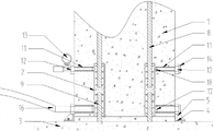
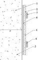
As Figure 1-4, in figure, mark 1-18 is respectively: prefabricated units 1, branch sleeve 2, lower member 3, elastomeric pad 4, Sealing formboard 5, adjust bolt 6, stirrup 7, precast reinforced 8, assembling reinforcing bar 9, flange 10, two-way tube connector 11, transition attaching nut 12, grouting pressure table 13, one way valve 14, grouting pump 15, Grouting Pipe 16, grout hole 17, overfolw hole 18.
Embodiment 1:
Referring to accompanying drawing 1, a kind of sleeve pressure type grout injection construction device connecting for reinforcing bar, relates generally between prefabricated units 1 and lower member 3 and is connected and fixed by branch sleeve 2 slip castings.Lower member 3 upper surfaces are raised with assembling reinforcing bar 9, and prefabricated units 1 are held in lower member 3.Prefabricated units 1 are rectangular-shaped structure, and its four sidewalls join and form L shaped turning with lower member 3 upper surfaces respectively.Prefabricated units 1 inside is embedded with some precast reinforced 8 and some branch sleeves 2, and it is precast reinforced 8 that the opening of branch sleeve 2 upper ends is fitted with, and lower ending opening is fitted with assembling reinforcing bar 9.On the sidewall of branch sleeve 2, offer and grout hole 17 and the overfolw hole 18 of its internal communication, wherein overfolw hole 18 is positioned at the top of grout hole 17.Especially it should be noted that owing to adopting overfolw hole 18 to be positioned at the tube-in-tube structure of the top of grout hole 17 herein, be different from conventional mode from bottom to top and be in the milk, but adopt high pressure slip casting from lower to upper, so just need formwork seal structure to seal.When branch sleeve 2 inside pour into after slurries, precast reinforced 8 and assembling be connected and fixed by branch sleeve 2 between reinforcing bar 9.But common grouting mode cannot ensure that its connection is all qualified, so ensure its qualification rate by the mode of high pressure slip casting.For this reason, set up formwork seal structure, mainly comprised elastomeric pad 4 and Sealing formboard 5.The concrete structure of above-mentioned related device is as follows:
Because prefabricated units 1 and lower member 3 have L shaped turning, so elastomeric pad 4 adopts Split type structure, even some in dry elasticity pad 4 are coated on the prefabricated units nearly lower member of 1 sidewall 3 places, and the end to end closed circular that is, 4 of remaining other elastomeric pads are placed in the upper surface of lower member 3, and form closed circular in prefabricated units 1 outer rim.The shape of Sealing formboard 5 main bodys and described prefabricated units 1 form fit, have rectangular-shaped inner chamber, and its lower end horizontal-extending is provided with flange 10.The main part of Sealing formboard 5 is set in outside elastomeric pad 4 and prefabricated units 1, and by stirrup 7, Sealing formboard, elastomeric pad 4 and prefabricated units 1 three is fixed.10 of flanges are pressed on the elastomeric pad 4 being arranged in lower member 3, and pass through flange 10, the elastomeric pad 4 and lower member 3 bolts of described Sealing formboard 5 by adjusting bolt 6.Thus, by elastomeric pad 4 and Sealing formboard 5, prefabricated units 1 and lower member 3 are sealed into one.The elastomeric material that elastomeric pad 4 can adopt intensity and elasticity to meet required performance is made, as vulcanized butyl rubber etc. not.
In the inner chamber of branch sleeve 2, pour into slurries for realizing, the side-walls of branch sleeve 2 nearly bottoms offers the grout hole 17 with its internal communication, and grout hole 17 is by the outward extending circular tube shaped of branch sleeve 2 sidewall; On branch sleeve 2, the side-walls of nearly upper end offers and the overfolw hole 18 of its internal communication, and overfolw hole 10 is equally by the outward extending circular tube shaped of branch sleeve 2 sidewall; The internal diameter of grout hole 17 is greater than overfolw hole 18 internal diameters.Be similarly the effect of playing sealing, on grout hole 17 and overfolw hole 18 inwalls, be provided with internal thread 8, the mode being threaded connection is connected with Grouting Pipe 16 parts such as grade, has ensured the sealing of grouting.
The present embodiment 1 relates to lower member 3 and prefabricated units 1 joint has the formwork seal structure at turning, so it should be recognized by those skilled in the art that above-mentioned hermetically-sealed construction is equally applicable to the prefabricated units 1 of cylindric or prism-shaped.
In conjunction with the specific descriptions of above-mentioned apparatus structure, the concrete steps when sleeve pressure type grout injection construction device connecting for reinforcing bar is installed and constructs are as follows:
Described prefabricated units 1 and lower member 3 have been docked;
In described some branch sleeves in prefabricated units 1, select any one branch sleeve 2, and the Grouting Pipe 16 that is tightly connected on the grout hole 17 of this branch sleeve 2, the overfolw hole 18 grouting pressure table 13 that is tightly connected, an one way valve 14 is all tightly connected on the grout hole 17 of residue branch sleeve 2 and overfolw hole 18.Because lower member 3 and lower member 3 joints have gap, branch sleeve 2 both ends open places have gap equally, so the state in being communicated with between branch sleeve 2.When slip casting, slurries can overflow from the lower ending opening of the branch sleeve of current slip casting 2, and enter in other branch sleeves 2, so need on the grout hole 17 of the branch sleeve 2 of slip casting and overfolw hole 18, one way valve not to be set;
At the coated elastomeric pad 4 in the surface at described prefabricated units 1 nearly lower member 3 places, and at the nearly prefabricated units 1 coated elastomeric pad 4 in surface, place of lower member 3.On elastomeric pad 4, be set with described Sealing formboard 5.Finally adopt adjustment bolt 6 and/or stirrup 7 that described Sealing formboard 5, elastomeric pad 4 are fixed in described prefabricated units 1 and lower member 3;
Adopt air pump by Grouting Pipe 16 to the interior ventilation of branch sleeve 2, to test the sealing performance at connection of thread, elastomeric pad 4 and Sealing formboard 5 places of described branch sleeve 2.When ventilation, the gas pouring in branch sleeve 2 enters in the inside and both gaps of prefabricated units 1 and lower member 3 from both ends open, and by elastomeric pad 4 and Sealing formboard 5 shutoff.So in the time that grouting pressure table 13 reading is normal, said structure sealing performance is qualified, carries out next step; As undesired (pressure is less than normal value), in above-mentioned hermetically-sealed construction, go wrong, check and revise after re-start ventilation test;
Drive by grouting pump 15, slurries are pumped in current branch sleeve 2 by Grouting Pipe 16;
Show that at grouting pressure table 13 pressure reaches after threshold value, stops slip casting.Threshold value described herein should be according to the concrete specification of grouting pump 15, Grouting Pipe 16, branch sleeve 2, and the sealing performance of hermetically-sealed construction is carried out concrete selection.Before practice of construction, should repeatedly test, reach how many times to determine that pressure in branch sleeve 2 and member is minimum, can guarantee that its inside there will not be hole, manometric threshold value when this numerical value is slip casting.
Stop after slip casting, unload Grouting Pipe 16 and grouting pressure table 13 on this branch sleeve 2, and the one way valve 14 that is tightly connected on its grout hole 17 and overfolw hole 18;
In above-mentioned residue branch sleeve 2, select any one, at its grout hole 17 Grouting Pipe 16, overfolw hole 18 grouting pressure table 13 that is tightly connected that is tightly connected;
Slurries are pumped in current branch sleeve 2 by Grouting Pipe 16, while being in the milk due to first branch sleeve 2, slurries have entered in all the other branch sleeves 2, confirm step so this step is actual for mending slurry, show after pressure reaches threshold value and stop slip casting until pressure meter.Successively residue branch sleeve 2 being mended to slurry afterwards confirms;
After slip casting completes, precast reinforced 8 after slurries solidify on prefabricated units 1 are connected complete with the assembling reinforcing bar 9 in lower member 3.
Embodiment 2:
Other structures of the present embodiment are identical with embodiment 1, and the structure of the formwork seal under different building structure is mainly provided, and referring to Fig. 4, lower member 3 and prefabricated units 1 have identical cross section, so can adopt an elastomeric pad 4 that the two is sealed simultaneously.Be that 4 times halves of elastomeric pad are coated on the nearly prefabricated units of lower member 31 surface, place, its first half is coated on the nearly lower member of prefabricated units 13 surfaces, place, and the end to end closed circular that is of entirety.Sealing formboard 5 entirety is set with elastomeric pad 4, afterwards by twice stirrup 7 press seals.
Be described in detail for the utility model embodiment by numerous different embodiment although above, it will be appreciated by those skilled in the art that the scope of law of this description is limited by the words of the utility model appending claims.It is exemplary that this detailed description should be construed as merely, instead of describe each possible embodiment.For the sealing that uses reinforcing steel bar connecting sleeve tube 2 positions in architectural construction, should be according to the concrete shape of the lower member 3 that is embedded with the prefabricated units 1 of branch sleeve 2 and assemble with prefabricated units 1, and the structure of the two joint, select the concrete structure of elastomeric pad 4 and Sealing formboard 5, and by suitable connector, the two is pressed abd fixed in prefabricated units 1 and lower member 3.
Claims (6)
1. the sleeve pressure type grout injection construction device connecting for reinforcing bar, comprise the lower member with assembling reinforcing bar and the prefabricated units that are embedded with some branch sleeves, described assembling reinforcing bar is plugged in described branch sleeve, on described branch sleeve sidewall, offer overfolw hole and be positioned at the grout hole of overfolw hole below, it is characterized in that: described construction equipment also comprises a pressure meter, a Grouting Pipe, some safety valves, Sealing formboard and at least one elastomeric pad; Described pressure meter is seal-installed in described some branch sleeves the overfolw hole place of any one, described Grouting Pipe is seal-installed on the grout hole place of this branch sleeve, and described some safety valves are seal-installed on overfolw hole and the grout hole place of residue branch sleeve one to one; Described elastomeric pad is coated on described lower member surface, nearly prefabricated units place and is coated on surface, described prefabricated units nearly lower member place; Described Sealing formboard is set in outside described elastomeric pad, and by described connector, described Sealing formboard, elastomeric pad is fixed in described prefabricated units and lower member.
2. a kind of sleeve pressure type grout injection construction device connecting for reinforcing bar according to claim 1, it is characterized in that: described prefabricated units sidewall and described lower member upper surface join and form L shaped structure, some in described some elastomeric pads are coated on described prefabricated units sidewall the end to end closed circular that is, residual elasticity pad is covered in described lower member upper surface and is closed circular around described prefabricated units, described Sealing formboard shape and described prefabricated units form fit are also set with described elastomeric pad and prefabricated units, described Sealing formboard lower end is provided with flange, described lower member upper surface, in described elastomeric pad and flange stack successively from the bottom to top.
3. a kind of sleeve pressure type grout injection construction device connecting for reinforcing bar according to claim 1, it is characterized in that: described connector comprises bolt, described bolt passes through described Sealing formboard, elastomeric pad and described prefabricated units and/or lower member bolt.
4. a kind of sleeve pressure type grout injection construction device connecting for reinforcing bar according to claim 1, is characterized in that: described connector comprises tightening device, and described tightening device is set in Sealing formboard outside.
5. a kind of sleeve pressure type grout injection construction device connecting for reinforcing bar according to claim 1, it is characterized in that: described grout hole and overfolw hole inwall are provided with internal thread, and the two-way tube connector that has all been threaded, the described two-way tube connector other end connection transition nuts that has been threaded, described connection transition nuts thread seal connects one way valve, pressure meter and Grouting Pipe.
6. a kind of sleeve pressure type grout injection construction device connecting for reinforcing bar according to claim 1, is characterized in that: described grout hole is positioned at the bottom of described branch sleeve sidewall.
Priority Applications (1)
| Application Number | Priority Date | Filing Date | Title |
|---|---|---|---|
| CN201110325139.XA CN102425309B (en) | 2011-10-24 | 2011-10-24 | Sleeve pressure type grouting construction device for connection of steel bars |
Applications Claiming Priority (1)
| Application Number | Priority Date | Filing Date | Title |
|---|---|---|---|
| CN201110325139.XA CN102425309B (en) | 2011-10-24 | 2011-10-24 | Sleeve pressure type grouting construction device for connection of steel bars |
Publications (2)
| Publication Number | Publication Date |
|---|---|
| CN102425309A CN102425309A (en) | 2012-04-25 |
| CN102425309B true CN102425309B (en) | 2014-07-02 |
Family
ID=45959334
Family Applications (1)
| Application Number | Title | Priority Date | Filing Date |
|---|---|---|---|
| CN201110325139.XA Active CN102425309B (en) | 2011-10-24 | 2011-10-24 | Sleeve pressure type grouting construction device for connection of steel bars |
Country Status (1)
| Country | Link |
|---|---|
| CN (1) | CN102425309B (en) |
Families Citing this family (2)
| Publication number | Priority date | Publication date | Assignee | Title |
|---|---|---|---|---|
| CN104727463B (en) * | 2015-03-25 | 2017-04-05 | 中国建筑第八工程局有限公司 | The grouting attachment structure of prefabricated components and its construction method |
| CN110593402A (en) * | 2019-10-14 | 2019-12-20 | 中建二局第二建筑工程有限公司 | Prefabricated column bottom angle steel seat slurry combination device and construction method |
Citations (3)
| Publication number | Priority date | Publication date | Assignee | Title |
|---|---|---|---|---|
| CN2707818Y (en) * | 2004-12-28 | 2005-07-06 | 上海市基础工程公司 | Bored pile post-pressure-grouting grouting device used for soft ground |
| CN101812899A (en) * | 2009-06-15 | 2010-08-25 | 黑龙江宇辉新型建筑材料有限公司 | Bifurcate lap connection of reinforcing steel bars and connection method thereof |
| CN202266039U (en) * | 2011-10-24 | 2012-06-06 | 上海市第二市政工程有限公司 | Sleeve pressure type grout injection construction device for steel bar connection |
Family Cites Families (1)
| Publication number | Priority date | Publication date | Assignee | Title |
|---|---|---|---|---|
| JPH0796840B2 (en) * | 1993-12-13 | 1995-10-18 | 株式会社淺沼組 | Reinforcing bar joining method |
-
2011
- 2011-10-24 CN CN201110325139.XA patent/CN102425309B/en active Active
Patent Citations (3)
| Publication number | Priority date | Publication date | Assignee | Title |
|---|---|---|---|---|
| CN2707818Y (en) * | 2004-12-28 | 2005-07-06 | 上海市基础工程公司 | Bored pile post-pressure-grouting grouting device used for soft ground |
| CN101812899A (en) * | 2009-06-15 | 2010-08-25 | 黑龙江宇辉新型建筑材料有限公司 | Bifurcate lap connection of reinforcing steel bars and connection method thereof |
| CN202266039U (en) * | 2011-10-24 | 2012-06-06 | 上海市第二市政工程有限公司 | Sleeve pressure type grout injection construction device for steel bar connection |
Non-Patent Citations (1)
| Title |
|---|
| JP特开平7-158278A 1995.06.20 |
Also Published As
| Publication number | Publication date |
|---|---|
| CN102425309A (en) | 2012-04-25 |
Similar Documents
| Publication | Publication Date | Title |
|---|---|---|
| CN102392511B (en) | Sleeve pressure type grouting construction method for steel reinforcement connection | |
| CN201217890Y (en) | Nested grouting reinforced steel coupling sleeve | |
| CN102359672B (en) | Prestressed steel cylinder concrete push pipe | |
| CN105019558A (en) | Steel bar anchoring connection structure and connection method for precast fabricated concrete components | |
| CN204850063U (en) | Prefabricated assembled concrete member's steel bar anchoring connection structure | |
| CN103982748B (en) | A kind of modified model pipeline stainless steel inner lining restorative procedure | |
| CN202266039U (en) | Sleeve pressure type grout injection construction device for steel bar connection | |
| CN202266018U (en) | Template sealing structure for grouting of connecting sleeve | |
| CN103590541A (en) | Grout sleeve for connecting prefabricated member steel bars and construction method of grout sleeve | |
| CN102425309B (en) | Sleeve pressure type grouting construction device for connection of steel bars | |
| CN202708461U (en) | Pipeline leakage stoppage device | |
| CN105014785A (en) | Steel bar anchoring preformed hole forming device and method for prefabricated assembled type concrete members | |
| CN102966185A (en) | Novel concrete-filled steel tube connection joint and construction method thereof | |
| CN204225279U (en) | The precast unit that nut break adrift grouting straight sleeve connects, assembling concrete component | |
| CN201560584U (en) | Quick connecting joint capable of being circularly used for pumping and lift-up of cast concrete | |
| CN204004780U (en) | Can peg graft concrete drain tile and the socket steel ring for this waste pipe | |
| CN201217889Y (en) | Plug-in type grouting reinforced steel coupling sleeve | |
| CN204844467U (en) | Prefabricated assembled steel bar anchoring preformed hole pore -forming device for concrete member | |
| CN204199543U (en) | The full grouting connecting reinforcement sleeve of the variable cross section realized by technique for rolling | |
| KR20140130978A (en) | The valve-housing | |
| CN202302366U (en) | Prestressed steel cylinder concrete jacking pipe | |
| CN112324055B (en) | Prefabricated vertical component and sleeve grouting construction method thereof | |
| CN104264908A (en) | Precast concrete members connected by locking and anchoring nuts and grouting variable diameter sleeve, prefabricated concrete member and manufacturing method of prefabricated concrete member | |
| CN202992424U (en) | Reinforced concrete pipe with sealing rod for jacking construction method | |
| CN205298949U (en) | Disconnect -type grout clamp tip sealing device |
Legal Events
| Date | Code | Title | Description |
|---|---|---|---|
| C06 | Publication | ||
| PB01 | Publication | ||
| C10 | Entry into substantive examination | ||
| SE01 | Entry into force of request for substantive examination | ||
| C53 | Correction of patent for invention or patent application | ||
| CB02 | Change of applicant information |
Address after: 200232 Xuhui District, Liuzhou Wu Road, Lane No. 13, No. 3, No. Applicant after: Shanghai urban construction Municipal Engineering (Group) Co., Ltd. Address before: 200232 Xuhui District, Liuzhou Wu Road, Lane No. 13, No. 3, No. Applicant before: Shanghai No.2 Municipal Engineering Co., Ltd. |
|
| COR | Change of bibliographic data |
Free format text: CORRECT: APPLICANT; FROM: SHANGHAI NO.2 MUNICIPAL ENGINEERING CO., LTD. TO: SHANGHAI UBAN CONSTRUCTION GROUP MUNICIPAL ENGINEERING (GROUP) CO., LTD. |
|
| C14 | Grant of patent or utility model | ||
| GR01 | Patent grant |