CN102257429B - Apparatus and method to control vacuum at porous material using multiple porous materials - Google Patents
Apparatus and method to control vacuum at porous material using multiple porous materials Download PDFInfo
- Publication number
- CN102257429B CN102257429B CN200980151106.9A CN200980151106A CN102257429B CN 102257429 B CN102257429 B CN 102257429B CN 200980151106 A CN200980151106 A CN 200980151106A CN 102257429 B CN102257429 B CN 102257429B
- Authority
- CN
- China
- Prior art keywords
- permeable members
- liquid permeable
- liquid
- chamber
- immersion
- Prior art date
- Legal status (The legal status is an assumption and is not a legal conclusion. Google has not performed a legal analysis and makes no representation as to the accuracy of the status listed.)
- Expired - Fee Related
Links
Images


Classifications
-
- G—PHYSICS
- G03—PHOTOGRAPHY; CINEMATOGRAPHY; ANALOGOUS TECHNIQUES USING WAVES OTHER THAN OPTICAL WAVES; ELECTROGRAPHY; HOLOGRAPHY
- G03F—PHOTOMECHANICAL PRODUCTION OF TEXTURED OR PATTERNED SURFACES, e.g. FOR PRINTING, FOR PROCESSING OF SEMICONDUCTOR DEVICES; MATERIALS THEREFOR; ORIGINALS THEREFOR; APPARATUS SPECIALLY ADAPTED THEREFOR
- G03F7/00—Photomechanical, e.g. photolithographic, production of textured or patterned surfaces, e.g. printing surfaces; Materials therefor, e.g. comprising photoresists; Apparatus specially adapted therefor
- G03F7/70—Microphotolithographic exposure; Apparatus therefor
- G03F7/70216—Mask projection systems
- G03F7/70341—Details of immersion lithography aspects, e.g. exposure media or control of immersion liquid supply
-
- G—PHYSICS
- G03—PHOTOGRAPHY; CINEMATOGRAPHY; ANALOGOUS TECHNIQUES USING WAVES OTHER THAN OPTICAL WAVES; ELECTROGRAPHY; HOLOGRAPHY
- G03B—APPARATUS OR ARRANGEMENTS FOR TAKING PHOTOGRAPHS OR FOR PROJECTING OR VIEWING THEM; APPARATUS OR ARRANGEMENTS EMPLOYING ANALOGOUS TECHNIQUES USING WAVES OTHER THAN OPTICAL WAVES; ACCESSORIES THEREFOR
- G03B27/00—Photographic printing apparatus
- G03B27/32—Projection printing apparatus, e.g. enlarger, copying camera
- G03B27/52—Details
Landscapes
- Physics & Mathematics (AREA)
- General Physics & Mathematics (AREA)
- Exposure And Positioning Against Photoresist Photosensitive Materials (AREA)
- Exposure Of Semiconductors, Excluding Electron Or Ion Beam Exposure (AREA)
Abstract
An immersion liquid confinement apparatus confines an immersion liquid in an immersion area that includes a gap between a projection system and an object of exposure in an immersion lithography system. The apparatus also recovers the immersion liquid from the immersion area. The apparatus includes a confinement member and first and second liquid-permeable members. The confinement member includes an outlet and an aperture through which a patterned image is projected onto the object. The first liquid-permeable member covers the outlet and has a first surface that faces the object and a second surface opposite the first surface, the second surface contacting a first chamber. The second liquid-permeable member has first and second oppositely-facing surfaces, the first surface of the second liquid-permeable member contacts the first chamber, the second surface of the second liquid-permeable member contacts a second chamber that is different from the first chamber.
Description
The cross reference of related application
The application states the U.S. Patent application the 12/573rd of submitting to October 5 2009 Christian era, the right of priority of No. 356, and the mode that the disclosure of this case is quoted is in full incorporated herein.The application's case is also stated the U.S. Provisional Patent Application the 61/193rd of submitting to October 22 2008 Christian era, the right of priority of No. 019, and the mode that the disclosure of this case is quoted is in full incorporated herein.The application's case is also stated the U.S. Provisional Patent Application the 61/272nd of submitting to September 9 2009 Christian era, the right of priority of No. 292, and the mode that the disclosure of this case is quoted is in full incorporated herein.
Technical field
The present invention relates to impregnated lithographic equipment and method, particularly relate to the apparatus and method that reclaim steeping liq.
Background technology
Typical lithographic equipment comprises radiation source, projection optical system and the substrate stage in order to support and the mobile substrate of wanting imaging.Before substrate is placed on substrate stage, on substrate surface, be coated with radiation-sensitive materials (for example resist).In operating process, use from the radiation energy of radiation source via projection optical system by the image projecting being defined by image-forming component on substrate.Projection optical system typically comprises multiple lens.The lens or the optical element that approach most substrate can be described as last or final optical element.
In exposure process, projection in zone is typically much smaller than substrate surface.Therefore, substrate is moved to make the whole patterned surface of substrate with respect to projection optical system.In semi-conductor industry, conventionally use the lithographic equipment of two types.Use so-called " stepping repeat (step-and-repeat) " device, whole image pattern in single exposure instantaneous projection on the target area of substrate.After exposure, substrate is moved in X and/or Y-direction or " stepping " and the new target area that exposes.Carry out this stepping repetitive process repeatedly, until whole substrate surface all exposes.Use sweep type lithographic equipment, target area is with continuous or " scanning " action exposure.For example, in the process of a target area of exposure, when image is by transmitted light during via light shield (reticle) or mask projection, light shield or mask move in one direction, and substrate moves on identical or reverse direction simultaneously.Subsequently, substrate moves to next scanning target area in X and/or Y-direction.Repeat this process until all dreamboats district on substrate all exposes.
Lithographic equipment is typically for making semiconductor wafer and flat-panel monitor imaging or patterning.As used herein word " substrate " generally represents the workpiece of any patternable, includes, but is not limited to semiconductor wafer and flat-panel monitor.
Impregnated photoetching be a kind of can be by using than thering is the expose technology of the resolution that improves photoetching exposure device of the large NA of accessible numerical aperture (NA) in known " dry type " photoetching exposure device of similar optical system.By the space between final optical element and the substrate of painting erosion resistant agent of filling optical projection system, impregnated photoetching can expose, otherwise light can internal reflection occur in the interface of optics and air.In impregnated etching system, may there is the numerical aperture of the refractive index (or the reckling in the refractive index of resist or lens material) up to steeping liq.Compare with the dry system with identical numerical aperture, liquid infiltration also makes the substrate depth of focus (also i.e. tolerable error on the upright position of substrate) increase along with the refractive index of steeping liq.Therefore, impregnated photoetching can make resolution increase and in fact without reducing the wavelength of exposure light.Therefore, be different from the displacement of the wavelength of exposure light, use impregnated photoetching will not need to develop new light sources, optical material (for illumination and optical projection system) or coating, and can allow to use and the same or similar resist of known " dry type " photoetching under identical wavelength.In the final optical element of optical projection system only and dipping systems that shell contacts with steeping liq with substrate (and perhaps also having part platform) thereof, most of technology of developing about dry lithography and design all can continue to be directly used in impregnated photoetching.
But, because substrate moves rapidly in typical light etching system, so the immersion liquid in Dilvar zone (comprising the space between optical projection system and substrate) is tended to be taken away Dilvar zone.If Dilvar zone is overflowed in immersion liquid, the operation of other elements in this liquid meeting disturb lithography system.In US2006/0152697 A1, describe a kind of method that reclaims immersion liquid and prevent immersion liquid pollution impregnated etching system, the mode that the disclosure of this case is quoted is in full incorporated herein.Also, referring to US2007/0222967 A1, the mode that the disclosure of this case is quoted is in full incorporated herein.
System described in US2006/0152697 A1 and US2007/0222967 A1 comprises immersion liquid limiting member.Immersion liquid limiting member comprises outlet, via this outlet, from Dilvar zone, reclaims (collection) immersion liquid.This outlet for example, is covered by fluid permeable member (screen cloth or poriness member).Vacuum control unit pair applies suction with the chamber that this outlet is connected, to immersion liquid is aspirated on substrate via fluid permeable member and outlet.It is very important that control puts on suction on fluid permeable member.
Summary of the invention
In said system, overlength liquid path be present in vacuum-control(led) system and the fluid permeable member settled towards substrate between (for example referring to US2006/0152697 Fig. 6 to Fig. 9).When the liquid on substrate (and/or substrate locking stage) first touches the lower surface of fluid permeable member, the length in liquid filling path may cause the delay that liquid sucks.When the flow rate in path changes suddenly, long liquid path also may cause occurring large pressure fluctuation at fluid permeable member place.
According to mode of the present invention, immersion liquid restraint device comprises first liquid permeable members and second liquid permeable members, with the Dilvar zone from impregnated etching system, remove liquid, this Dilvar zone comprises for example, gap between optical projection system and object (substrate, substrate locking stage or both).Outlet in first liquid permeable members coverage limitation member, and there is OO first surface and second surface relative with first surface and that contact with the first chamber.Second liquid permeable members is be placed in the first chamber and comprise and separating with the second surface of first liquid permeable members and first surface corresponding thereto.Second liquid permeable members also comprises the second surface relative with its first surface.The second surface of second liquid permeable members contacts with the second chamber that is different from the first chamber.
According to preferred specific embodiment, the first vacuum system and the second vacuum system couple with the first chamber and the second chamber respectively.Aspirate immersion liquid and immersion liquid is entered the first chamber via first liquid permeable members from Dilvar zone with the first vacuum system that the first chamber couples, so that liquid flow to the second surface of first liquid permeable members from the first surface of first liquid permeable members.Preferably liquid is not delivered to the first vacuum system from the first chamber.Therefore, between first liquid permeable members and the first vacuum system, there is not overlength liquid path.The second vacuum system and the second chamber couple, and from the first chamber pumping liquid and liquid is entered the second chamber via second liquid permeable members, so that liquid flow to its second surface via second liquid permeable members from its first surface.
The second vacuum system is also from the second chamber suction immersion liquid, so that liquid can be treated and/or recycle resupplying to Dilvar zone via for example immersion liquid feed system.Although may there is overlength liquid path because of the not direct object-oriented (substrate, Substrate table etc.) of second liquid permeable members between the second vacuum system and second liquid permeable members, can not affect the pressure in the first chamber by the caused pressure surge of mobile variation via second liquid permeable members.
According to some specific embodiments, the distance between second liquid permeable members and first liquid permeable members is for the different piece of the first surface of second liquid permeable members and change.For example, the first surface of second liquid permeable members can or tilt with respect to first liquid permeable members projection.This is avoided wrapping bubble on the first surface of second liquid permeable members, and the flow rate that is easier to adapt to the liquid of collecting via second liquid permeable members changes.
First liquid permeable members and second liquid permeable members can be screen cloth or poriness member, for example sponge or plate, and this plate has the hole of running through whole plate extension.
First liquid permeable members can be identical with the structure of second liquid permeable members, or can be in aperture, thickness and porosity at least one aspect difference.
Other modes of the present invention relate to a kind of impregnated lithographic equipment, and it has optical projection system, be movable to the moveable platform of optical projection system lower position and fixed object (for example substrate) and according to the limiting member of mode of the present invention.
Other modes of the present invention relate to the method for using impregnated lithographic equipment to manufacture element.
Accompanying drawing explanation
Fig. 1 is the simplification front elevation that schematically illustrates the impregnated etching system of specific embodiments more of the present invention;
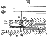
Fig. 2 is the liquid limiting member of the first specific embodiment of the present invention and the simplified side cut-open view of liquid removal system thereof;
Fig. 3 is the liquid limiting member of the second specific embodiment of the present invention and the simplified side cut-open view of liquid removal system thereof;
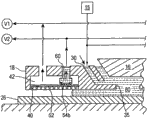
Fig. 4 is the liquid limiting member of the 3rd specific embodiment of the present invention and the simplified side cut-open view of liquid removal system thereof;
Fig. 5 is the process flow diagram that the method for element of the present invention is manufactured in general introduction; And
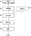
Fig. 6 is the process flow diagram of summarizing more in detail element processing.
Embodiment
The present invention is described in connection with the accompanying drawing of following exemplary specific embodiment, and wherein same tag represents similar elements.
Fig. 1 illustrates impregnated etching system 10, and it comprises light shield platform 12, supports light shield on it; Optical projection system 14, it has last or " finally " optical element 16; With meticulous mobile platform 22, supporting substrate 26 on it, this platform can move again on rough mobile platform 20.Immersion liquid supply and retracting device 18 (being sometimes referred to as liquid limiting member 18 herein) are settled so that steeping liq is reclaimed in the 28He Cong gap, gap 28 that steeping liq (it can be the liquid of for example water) is supplied between final optical element 16 and substrate 26 around the final optical element 16 of optical projection system 14.In the specific embodiment of the invention, impregnated etching system 10 is scanning photoetching system, wherein light shield and substrate 26 synchronizing moving on direction of scanning separately in scan exposure operating process.Meticulous mobile platform 22 is to control the position of substrate 26 in one or more in X, Y, Z, θ X, θ Y and θ Z direction (preferably all) direction than the high precision of rough mobile platform 20, as well-known in technique, rough mobile platform 20 is mainly used in moving substrate 26 in long distance.The upper surface of meticulous mobile platform 22 comprises substrate holder, and it preferably has the dimple of fixing base 26.In addition, a part of upper surface around the meticulous mobile platform 22 of fixing base has concordant with the upper surface of fixing base in fact upper surface, so that when Dilvar zone is positioned near substrate edges place, liquid still maintains between liquid limiting member 18 and substrate 26 and the upper surface of substrate holder.
The light source of etching system can be light source, the g line source (436nm) of for example mercury or i line source (365nm), KrF excimer laser (248nm), ArF excimer laser (193nm) or F2 laser instrument (157nm).Optical projection system 14 will be passed the light projection of light shield and/or focus on substrate 26.Depend on the design of exposure device, optical projection system 14 can zoom in or out the image irradiating on light shield.It also can be 1 times of amplification system.
When using far ultraviolet radiation (for example, from excimer laser), can in optical projection system 14, use the far ultraviolet glass material of transmission, for example quartz glass and calcium fluoride.Optical projection system 14 can be Reflected refraction type no, complete refraction type or completely reflective.
About exposure element, can consider to use reflection-refraction type optical system.The embodiment of reflection-refraction type optical system is at United States Patent (USP) the 5th, and 668, No. 672 and United States Patent (USP) the 5th, shown in 835, No. 275.In these Patent Cases, reflective optical devices can be the reflection and refraction optical system that comprises beam splitter and concave mirror.United States Patent (USP) the 5th, is also used for 689, No. 377 to comprise concave mirror etc. but without the reflection-refraction type optical system of beam splitter, and also can be the present invention and adopt.The mode that the disclosure of above-mentioned United States Patent (USP) is quoted is in full incorporated herein.
Fig. 2 is the cut-open view of the specific embodiment of liquid limiting member 18.As shown in Figure 2, liquid limiting member 18 maintains immersion liquid 80 in Dilvar zone, and this Dilvar zone comprises gap or the space between the final optical element 16 of optical projection system 14 and a part of upper surface of substrate 26.Immersion liquid 80 in Fig. 2 can be regarded as only accounting for a part of upper surface of substrate 26.That is the size that, the size of Dilvar zone is less than substrate 26 upper surfaces is so that a part of upper surface of covered substrate only.Depend on that substrate 26 is about optical projection system 14 relative position of (with liquid limiting member 18), Dilvar zone can be placed on substrate, be placed in a part for substrate and in a part for the substrate holder of substrate, or be only placed in the part of substrate holder (for example, when substrate moves so that its while being no longer placed in optical projection system 14 below).In addition,, if exposure device comprises the measuring table for measuring about optical projection system 14, Dilvar zone can form (on measuring table, will not have substrate holder) between the upper surface of measuring table and final optical element 16.
Liquid limiting member 18 comprises at least one (and preferably more than one) liquid supply entrance 30, and immersion liquid 80 is supplied with Dilvar zone via this entrance.Liquid is supplied to and supplies with entrance 30 via feed path, and one end of feed path is connected to liquid feeder 15 and the other end and is connected to the inlet manifold of liquid limiting member 18.Be supplied to the liquid of supplying with entrance 30 to arrive substrate 26 after passing the hole 35 that is placed in limiting member 18 centers.As shown in Figure 2, the supply of immersion liquid and recovery are through controlling so that the immersion liquid liquid level between liquid limiting member 18 and final optical element 16 maintains the lower surface top of final optical element 16, thereby make before arriving substrate 26, only to pass immersion liquid (that is, exposure light is through any air or gas) via the exposure light of optical projection system 14 transmissions.
In the specific embodiment of Fig. 2, liquid limiting member 18 comprises outlet 40.Around hole 35 and therefore in the specific embodiment of Fig. 2, outlet 40 is also around the ring groove of Dilvar zone.Liquid removes from Dilvar zone and from the surface (and/or surface of substrate holder) of substrate 26 via going out 40.Go out 40 and covered by first liquid permeable members 52, the first chamber 42 is placed in liquid limiting member 18 at least in part.First liquid permeable members 52 first (under) surface towards substrate 26, and first liquid permeable members 52 second (on) surface contact with chamber 42.Therefore the liquid, passing from first surface to the second surface of first liquid permeable members 52 enters the first chamber 42.
Although Fig. 2 middle outlet 40 (and therefore first liquid permeable members 52) is succeeding vat, (with the therefore first liquid permeable members 52 of cover outlet) can be a series of arch sections, straight line portion or the angled portion that jointly around Dilvar zone and with the first chamber 42, are communicated with to go out 40.In addition, outlet can be any other shape on circle, rectangle or the planimetric map on planimetric map.
Second liquid permeable members 54 be placed in the first chamber 42 and comprise first (under) surface, this surface and first liquid permeable members 52 second (on) surface separate and towards this second (on) surface.Second liquid permeable members 54 also comprise relative with its first surface and contact with the second chamber 60 second (on) surface.Therefore, the second chamber 60 is to be defined by second liquid permeable members 54 and wall or other structures.
The first chamber 42 is communicated with the first vacuum system V1 that the first chamber 42 is applied to suction.This suction is enough to immersion liquid to be pumped in the first chamber 42 via first liquid permeable members 52.The first vacuum system V1 is through controlling so that the suction putting in first liquid permeable members 52 maintains below the bubbling point of first liquid permeable members 52.; the first vacuum system V1 controls the pressure in the first chamber 42; in fact only liquid is removed from the surface (and/or surface of substrate holder) of Dilvar zone and/or substrate 26 via first liquid permeable members 52, and remove from the surface (and/or surface of substrate holder) of substrate 26 without gas.But the first vacuum system V1 does not make liquid remove from the first chamber 42.
More precisely, the second vacuum system V2 being communicated with the second chamber 60 makes the liquid in the first chamber 42 enter in the second chamber 60 via 54 suctions of second liquid permeable members.Subsequently, the liquid in the second chamber 60 removes from the second chamber 60 via the suction being produced by the second vacuum system V2.The second vacuum system V2 is through controlling so that the suction putting in second liquid permeable members 54 maintains below the bubbling point of second liquid permeable members 54.That is, the second vacuum system V2 controls the pressure in the second chamber 60, in fact only liquid is removed from the first chamber 42 via second liquid permeable members 54, and remove from the first chamber 42 without gas.Vacuum system V1 and V2 can be the system of controlling vacuum power described in for example US2006/0152697 A1 and US2007/0222967 A1, and the mode that the disclosure of each case is all quoted is in full incorporated herein.
Now by describing, control liquid limiting member 18 to remove the mode of liquid.
To for example system of system described in US2006/0152697 A1 be described herein.Seemingly, but there is not the second chamber 60, second liquid permeable members 54 or the second vacuum-control(led) system V2 in the system class shown in the system of US2006/0152697 A1 and Fig. 2 of the application.The system of US2006/0152697 A1 is only for example, via single liquid permeable members (applicant is in the first liquid permeable members 52 shown in Fig. 2) suction immersion liquid.Liquid filling single chamber, for example the first chamber 42, and liquid for example, is pulled out chamber 42 by single vacuum system (applicant is at the system V1 shown in Fig. 2).Therefore, in vacuum system and between the fluid permeable member of substrate, there is overlength liquid path.Thereby, as discussed previously, when liquid touches the lower surface of fluid permeable member at first, because the liquid accelerating in overlength liquid path needs the time, so exist and postpone while reclaiming this liquid.In addition, when the flow rate in path changes suddenly, long liquid path can cause occurring large pressure fluctuation, for example, when the exposure of each substrate starts and finishes and for example difference on substrate hit while there is the fast moving of substrate between the exposure of district (shot area), there will be large pressure fluctuation.Therefore,, for avoiding exceeding the bubbling point of fluid permeable member, the suction being provided by vacuum-control(led) system is typically reduced in fact lower than exceeding the suction of bubbling point of fluid permeable member.Therefore,, even if there is pressure fluctuation, vacuum power also can not exceed the bubbling point of fluid permeable member.But, reduce the further reactivity of reduction liquid recovery system of suction, for example, when liquid touches fluid permeable member at first.This can make liquid overflow from liquid limiting member.Reduce the maximum flow rates that suction also reduces collectable liquid.For example, in the bubbling point of fluid permeable member is the system of 2 kPas, vacuum-control(led) system can be through controlling so that the steady state (SS) suction putting on fluid permeable member is approximately 1 kPa.
Applicant in the system described in Fig. 2, can the suction of the bubbling point that approaches very much first liquid permeable members be put in first liquid permeable members by the first vacuum-control(led) system V1, because there is extremely short liquid path in the first liquid permeable members 52 in the first chamber 42.Particularly, the distance approximately equal between the lower surface of the length of liquid path and second liquid permeable members 54 and the upper surface of first liquid permeable members 52.This distance can be as small as 3 millimeters.
Because form short liquid path above first liquid permeable members 52, so when liquid touches the lower surface of first liquid permeable members 52 first, liquid sucks in fact and do not postpone.In addition, when can the flow rate in this path not changing suddenly, the short liquid path forming above first liquid permeable members 52 cause large pressure fluctuation to occur.Therefore, the first vacuum-control(led) system V1 can be through controlling to first liquid permeable members is applied to the suction of the bubbling point that extremely approaches first liquid permeable members 52.Therefore, regardless of via first liquid permeable members 52 flowing liquid speed, all stabilizer poles of situation that first liquid permeable members 52 places exist.
To the mobile control via second liquid permeable members 54 with above about to described similar via the control of system flow with single liquid permeable members.Particularly, by the second vacuum-control(led) system V2, put on suction that suction in second liquid permeable members 54 maintains second liquid permeable members 54 places fully lower than the bubbling point of second liquid permeable members 54, so that when liquid flow exists variation suddenly, the large pressure fluctuation that second liquid permeable members 54 places may occur can not exceed the bubbling point of second liquid permeable members 54.But, when there is large mobile variation, the excess liq that cannot enough aspirate fast via second liquid permeable members 54 is at first housed inside (, when increasing via flowing of first liquid permeable members 52 is rapid, the liquid level in the first chamber 42 will rise) in the first chamber 42.But when the rapid increase and decrease of flowing is less and via the mobile arrival of second liquid permeable members 54 during compared with steady state (SS), the liquid level in the first chamber 42 will reduce until it realizes the stability state shown in Fig. 2 gradually.
Although it is horizontal in fact that the second liquid permeable members 54 in Fig. 2 is depicted as, but second liquid permeable members 54 is preferably through arranging so that it is not along its whole surface level, because when liquid stream is lower, may catch bubble below the lower surface of flat horizontal member 54.Therefore, substituting specific embodiment shown in Fig. 3 and Fig. 4 provides a kind of second liquid permeable members, and wherein the distance between the lower surface of second liquid permeable members and the upper surface of first liquid permeable members is for the different piece of second liquid permeable members and change.
Fig. 3 illustrates a specific embodiment, wherein second liquid permeable members 54a tilt so that wherein a part than another part of second liquid permeable members 54a closer to first liquid permeable members 52.
Fig. 4 illustrates a specific embodiment, and wherein second liquid permeable members 54b projection, so that wherein different piece and first liquid permeable members 52 separate different distance.
The specific embodiment of Fig. 3 and Fig. 4 is also due to following former thereby favourable: it can be easier to adapt to the mobile variation via first liquid permeable members 52, because when flow rate increases, the more multizone of second liquid permeable members 54a or 54b will contact with the liquid in chamber 42, thereby increases the flow rate ability via second liquid permeable members 54a/54b.
In some specific embodiment, steeping liq is the liquid with high index of refraction.In different specific embodiments, this liquid can be pure water, or includes, but is not limited to the liquid of cedar oil, fluorine-based oil, " decahydronaphthalene " or " perhydro pyrene ".
First liquid permeable members 52 or second liquid permeable members 54 or first liquid permeable members and second liquid permeable members can be poriness member, for example screen cloth, or can be formed by the porous material with the big or small hole that is typically less than 150 microns.For example, poriness member can be silk screen (comprising braided part or the material layer made by metal, plastics or its analog), porous metal, porous glass, porous plastic, porous ceramics, sponge or the material piece with chemical etching hole (for example, by photoetching).First liquid permeable members can be identical with the structure of second liquid permeable members, or can be in aperture size, thickness and porosity one or more aspect difference.In some specific embodiment, the first vacuum system V1 can be through controlling so that put on that suction in first liquid permeable members 52 maintains the bubbling point place of first liquid permeable members 52 or more than bubbling point.That is, the first vacuum system V1 can control the pressure in the first chamber 42, and the potpourri of liquid and gas is removed from the surface (and/or surface of substrate holder) of Dilvar zone and/or substrate 26 via first liquid permeable members 52.In some specific embodiment, the second vacuum system V2 can be through controlling so that put on that suction in second liquid permeable members 54 maintains the bubbling point place of second liquid permeable members 54 or more than bubbling point.That is, the second vacuum system V2 can control the pressure in the second chamber 60, and the potpourri of liquid and gas is removed from the first chamber 42 via second liquid permeable members 54.
The use of exposure device as herein described is not limited to the etching system of manufacturing for semiconductor.For example, exposure device can be used as the LCD etching system of liquid crystal display cells pattern that exposes in rectangular glass, or manufactures the etching system of thin-film head.
Semiconductor element can be used said system, generally by the process shown in Fig. 5, manufactures.In step 801, design function and the Performance Characteristics of this element.Then,, in step 802, according to the previous design procedure design figuratum mask of tool (light shield), and by silicon materials, manufacture wafer in step 803.In step 804, by above according to the present invention, the etching system described in mode is exposed to the mask pattern of design in step 802 on the wafer from step 803.In step 805, assembling semiconductor element (comprise cutting process, cohere process and encapsulation process).Finally, check element in step 806 subsequently.
Fig. 6 explanation is at the detail flowchart embodiment that manufactures the above-mentioned steps 804 in semiconductor element situation.In Fig. 6, in step 811 (oxidation step), make wafer surface oxidation.In step 812 (CVD step), in wafer surface, form dielectric film.In step 813 (electrode formation step), by vapour deposition, on wafer, form electrode.In step 814 (implanted ions step), implanting ions in wafer.The pre-treatment step of wafer in above-mentioned steps 811 to 814 formation wafer processing procedures, and select each step according to processing requirements.
In each processing of wafers stage, when above-mentioned pre-treatment step has completed, implement following post-processing step.In last handling process, first, in step 815 (photoresist formation step), photoresist is applied on wafer.Then,, in step 816 (step of exposure), use above-mentioned exposure element that the circuit pattern of mask (light shield) is transferred to wafer.In step 817 (development step), the wafer that will expose develops subsequently, and in step 818 (etching step), by etching, removes the part (exposed material surface) beyond residual light resist.In step 819 (photoresist removes step), remove remaining unnecessary light resist after etching.By repeating these pre-service and post-processing step, form multiple circuit pattern.
According to the etching system of specific embodiment as herein described (exposure device), can build by assembling various subsystems in the mode that makes to specify mechanical precision, electricity degree of accuracy and optics degree of accuracy to be maintained.For maintaining various degree of accuracy, before assembling and after assembling, each optical system is through regulating to reach its optics degree of accuracy.Equally, each mechanical system and each electric system are also through regulating to reach its mechanical precision and electricity degree of accuracy separately.The process that each subsystem is assembled into etching system is included between each subsystem provides mechanical interface, wiring to connect and be connected with air pressure pipe arrangement.Each subsystem also before various subsystems assembling etching systems through assembling.When using various subsystem assembling etching system, carry out always regulating to guarantee maintaining degree of accuracy in the etching system completing.In addition, may in the clean room that temperature and cleanliness are controlled, manufacture exposure system.
Although describe the present invention with reference to preferred specific embodiment of the present invention, should be appreciated that, the invention is not restricted to these preferred specific embodiment or structures.This invention is intended to contain various improvement and equivalent.In addition, although at the preferred various elements of specific embodiment shown in various exemplary combination and configuration, other combinations and configuration, comprise more, less or only single element also within spirit of the present invention and category.
Claims (40)
1. an immersion liquid restraint device, for immersion liquid being limited in Dilvar zone at impregnated etching system, this Dilvar zone comprises the gap between optical projection system and exposure object, and this device also reclaims this immersion liquid from this Dilvar zone, and this device comprises:
Limiting member, it comprise outlet and hole, wherein pattern image via this hole projection on this object;
First liquid permeable members, it covers this outlet and has towards the first surface of this object and the second surface relative with this first surface, and this second surface contacts with the first chamber; With
Second liquid permeable members, it is arranged to be adjacent to the second surface of this first liquid permeable members and separates with the second surface of first liquid permeable members, this second liquid permeable members has the first surface and the second surface relative with the first surface of this second liquid permeable members towards the second surface of this first liquid permeable members, the second surface of this second liquid permeable members contacts with the second chamber that is different from this first chamber
Wherein this first liquid permeable members is screen cloth or poriness member,
This second liquid permeable members is screen cloth or poriness member, and
This immersion liquid is recovered to this first chamber via this first liquid permeable members, and this immersion liquid is recovered to this second chamber via this second liquid permeable members from this first chamber.
2. immersion liquid restraint device as claimed in claim 1, wherein the distance between this second liquid permeable members and this first liquid permeable members is for the different piece of the first surface of this second liquid permeable members and change.
3. immersion liquid restraint device as claimed in claim 2, wherein the first surface of this second liquid permeable members is protruding.
4. immersion liquid restraint device as claimed in claim 2, wherein this second liquid permeable members tilts with respect to this first liquid permeable members.
5. immersion liquid restraint device as claimed in claim 1, wherein this poriness member is sponge.
6. immersion liquid restraint device as claimed in claim 1, wherein this poriness member is plate, this plate has the hole of running through whole plate extension.
7. immersion liquid restraint device as claimed in claim 1, wherein the distance between the second surface of this first liquid permeable members and the first surface of this second liquid permeable members is at least about 3 millimeters.
8. immersion liquid restraint device as claimed in claim 1, wherein different aspect this first liquid permeable members and at least one in size, thickness and the porosity in hole of this second liquid permeable members.
9. an immersion liquid restraint device, for immersion liquid being limited in Dilvar zone at impregnated etching system, this Dilvar zone comprises the gap between optical projection system and exposure object, and this device also reclaims this immersion liquid from this Dilvar zone, and this device comprises:
Limiting member, it comprise outlet and hole, wherein pattern image via this hole projection on this object;
First liquid permeable members, it covers this outlet and has towards the first surface of this object and the second surface relative with this first surface, and this second surface contacts with the first chamber; With
Second liquid permeable members, it has the first and second right surfaces of opposite face, the first surface of this second liquid permeable members contacts with this first chamber, and the second surface of this second liquid permeable members contacts with the second chamber that is different from this first chamber
Wherein this first liquid permeable members is screen cloth or poriness member,
This second liquid permeable members is screen cloth or poriness member, and
This immersion liquid is recovered to this first chamber via this first liquid permeable members, and this immersion liquid is recovered to this second chamber via this second liquid permeable members from this first chamber.
10. immersion liquid restraint device as claimed in claim 9, wherein this first liquid permeable members is flatly settled, and the first surface of this second liquid permeable members is placed in and the vertical position separating of second surface of this first liquid permeable members.
11. immersion liquid restraint devices as claimed in claim 10, wherein the vertical range between the first surface of this second liquid permeable members and the second surface of this first liquid permeable members is for the different piece of the first surface of this second liquid permeable members and change.
12. immersion liquid restraint devices as claimed in claim 11, wherein the first surface of this second liquid permeable members is protruding.
13. immersion liquid restraint devices as claimed in claim 11, wherein this second liquid permeable members tilts with respect to this first liquid permeable members.
14. immersion liquid restraint device as claimed in claim 9, wherein this poriness member is sponge.
15. immersion liquid restraint devices as claimed in claim 9, wherein this poriness member is plate, this plate has the hole of running through whole plate extension.
16. immersion liquid restraint devices as claimed in claim 9, wherein the vertical range between the second surface of this first liquid permeable members and the first surface of this second liquid permeable members is at least about 3 millimeters.
17. 1 kinds of impregnated lithographic equipments, comprising:
Optical projection system, it has final optical element;
Moveable platform, it is movable to this optical projection system lower position, makes to have gap between this final optical element and the surface of this platform, and immersion liquid is filled in the gap between this surface and this final optical element; With
Limiting member, it is maintained at this immersion liquid in this gap between this surface and this final optical element, and this limiting member comprises:
Outlet;
Hole, this optical projection system is projected to pattern image on this moveable platform by this immersion liquid via this hole;
First liquid permeable members, it covers this outlet and has the surperficial first surface and the second surface relative with this first surface towards this platform, and this second surface contacts with the first chamber; With
Second liquid permeable members, it is arranged to be adjacent to the second surface of this first liquid permeable members and separates with the second surface of this first liquid permeable members, this second liquid permeable members has the first surface and the second surface relative with the first surface of this second liquid permeable members towards the second surface of this first liquid permeable members, the second surface of this second liquid permeable members contacts with the second chamber that is different from this first chamber
Wherein this first liquid permeable members is screen cloth or poriness member,
This second liquid permeable members is screen cloth or poriness member, and
This immersion liquid is recovered to this first chamber via this first liquid permeable members, and this immersion liquid is recovered to this second chamber via this second liquid permeable members from this first chamber.
18. impregnated lithographic equipments as claimed in claim 17, it further comprises:
The first vacuum system with this first chamber couples, enters this first chamber to aspirate this immersion liquid via this first liquid permeable members from first surface to the second surface of this first liquid permeable members of this first liquid permeable members.
19. impregnated lithographic equipments as claimed in claim 18, it further comprises:
With the second vacuum system that this second chamber couples, this immersion liquid system enters this second chamber from this first chamber suction via this second liquid permeable members by this second vacuum system.
20. impregnated lithographic equipments as claimed in claim 17, wherein the distance between this second liquid permeable members and this first liquid permeable members is for the different piece of the first surface of this second liquid permeable members and change.
21. impregnated lithographic equipments as claimed in claim 20, wherein the first surface of this second liquid permeable members is protruding.
22. impregnated lithographic equipments as claimed in claim 20, wherein this second liquid permeable members tilts with respect to this first liquid permeable members.
23. impregnated lithographic equipment as claimed in claim 17, wherein this poriness member is sponge.
24. impregnated lithographic equipments as claimed in claim 17, wherein this poriness member is plate, this plate has the hole of running through whole plate extension.
25. impregnated lithographic equipments as claimed in claim 17, wherein the distance between the second surface of this first liquid permeable members and the first surface of this second liquid permeable members is at least about 3 millimeters.
26. impregnated lithographic equipments as claimed in claim 17, wherein different aspect this first liquid permeable members and at least one in size, thickness and the porosity in hole of this second liquid permeable members.
27. impregnated lithographic equipments as claimed in claim 17, wherein this limiting member is in fact around the final optical element of this optical projection system.
28. impregnated lithographic equipments as claimed in claim 17, wherein this platform comprises substrate holder, and the upper surface of the upper surface of this substrate holder, the substrate fixed by this substrate holder or both, corresponding to and this final optical element between form the surface in this gap.
29. impregnated lithographic equipments as claimed in claim 17, wherein the potpourri of this immersion liquid and gas is recovered to this first chamber via this first liquid permeable members.
30. impregnated lithographic equipments as claimed in claim 29, wherein in fact only this immersion liquid is recovered to this second chamber from this first chamber.
31. 1 kinds of manufacturing methods, comprising:
By by pattern image via the optical projection system projection of immersion liquid and impregnated lithographic equipment as claimed in claim 17 this substrate that exposes on substrate; With
This exposure base is developed.
32. 1 kinds of Dilvar zones from impregnated etching system reclaim the method for immersion liquid, and this Dilvar zone comprises the gap between optical projection system and exposure object, and the method comprises:
Via first liquid permeable members, from this Dilvar zone, aspirating this immersion liquid enters to small part and is placed in the first chamber in limiting member, this limiting member comprises outlet and hole, wherein pattern image via this hole projection on this object, this outlet comprises the first liquid permeable members of this this outlet of covering, this first liquid permeable members has towards the first surface of this object and the second surface relative with this first surface, and this second surface contacts with this first chamber; With
Via second liquid permeable members, from this first chamber, aspirating this immersion liquid enters the second chamber, this second liquid permeable members is placed in the boundary between this first chamber and this second chamber, this second liquid permeable members has the first surface separating towards the second surface of this first liquid permeable members and with the second surface of this first liquid permeable members, this second liquid permeable members has the first surface second surface relative and that contact with this second chamber with this second liquid permeable members
Wherein this first liquid permeable members is screen cloth or poriness member,
This second liquid permeable members is screen cloth or poriness member, and
This immersion liquid is recovered to this first chamber via this first liquid permeable members, and this immersion liquid is recovered to this second chamber via this second liquid permeable members from this first chamber.
33. methods as claimed in claim 32, wherein:
This immersion liquid enters in this first chamber via this first liquid permeable members suction by this first chamber is coupled to the first vacuum system; With
This immersion liquid enters in this second chamber via this second liquid permeable members suction by this second chamber is coupled to the second vacuum system.
34. methods as claimed in claim 32, wherein the distance between this second liquid permeable members and this first liquid permeable members is for the different piece of the first surface of this second liquid permeable members and change.
35. method as claimed in claim 34, wherein the first surface of this second liquid permeable members is protruding.
36. method as claimed in claim 34, wherein this second liquid permeable members tilts with respect to this first liquid permeable members.
37. methods as claimed in claim 32, wherein this poriness member is sponge.
38. methods as claimed in claim 32, wherein this poriness member is plate, this plate has the hole of running through whole plate extension.
39. methods as claimed in claim 32, wherein the distance between the second surface of this first liquid permeable members and the first surface of this second liquid permeable members is at least about 3 millimeters.
40. methods as claimed in claim 32 are wherein different aspect this first liquid permeable members and at least one in size, thickness and the porosity in hole of this second liquid permeable members.
Applications Claiming Priority (7)
| Application Number | Priority Date | Filing Date | Title |
|---|---|---|---|
| US19301908P | 2008-10-22 | 2008-10-22 | |
| US61/193,019 | 2008-10-22 | ||
| US27229209P | 2009-09-09 | 2009-09-09 | |
| US61/272,292 | 2009-09-09 | ||
| US12/573,356 US8477284B2 (en) | 2008-10-22 | 2009-10-05 | Apparatus and method to control vacuum at porous material using multiple porous materials |
| US12/573,356 | 2009-10-05 | ||
| PCT/US2009/061499 WO2010048299A1 (en) | 2008-10-22 | 2009-10-21 | Apparatus and method to control vacuum at porous material using multiple porous materials |
Publications (2)
| Publication Number | Publication Date |
|---|---|
| CN102257429A CN102257429A (en) | 2011-11-23 |
| CN102257429B true CN102257429B (en) | 2014-04-30 |
Family
ID=42108386
Family Applications (1)
| Application Number | Title | Priority Date | Filing Date |
|---|---|---|---|
| CN200980151106.9A Expired - Fee Related CN102257429B (en) | 2008-10-22 | 2009-10-21 | Apparatus and method to control vacuum at porous material using multiple porous materials |
Country Status (6)
| Country | Link |
|---|---|
| US (2) | US8477284B2 (en) |
| JP (1) | JP5682830B2 (en) |
| KR (1) | KR101647859B1 (en) |
| CN (1) | CN102257429B (en) |
| TW (1) | TWI475329B (en) |
| WO (1) | WO2010048299A1 (en) |
Families Citing this family (12)
| Publication number | Priority date | Publication date | Assignee | Title |
|---|---|---|---|---|
| NL2003226A (en) * | 2008-08-19 | 2010-03-09 | Asml Netherlands Bv | Lithographic apparatus, drying device, metrology apparatus and device manufacturing method. |
| US8634055B2 (en) * | 2008-10-22 | 2014-01-21 | Nikon Corporation | Apparatus and method to control vacuum at porous material using multiple porous materials |
| US8477284B2 (en) | 2008-10-22 | 2013-07-02 | Nikon Corporation | Apparatus and method to control vacuum at porous material using multiple porous materials |
| JP5001343B2 (en) * | 2008-12-11 | 2012-08-15 | エーエスエムエル ネザーランズ ビー.ブイ. | Fluid extraction system, immersion lithographic apparatus, and method for reducing pressure fluctuations of an immersion liquid used in an immersion lithographic apparatus |
| US20110222031A1 (en) * | 2010-03-12 | 2011-09-15 | Nikon Corporation | Liquid immersion member, exposure apparatus, liquid recovering method, device fabricating method, program, and storage medium |
| US20120013864A1 (en) * | 2010-07-14 | 2012-01-19 | Nikon Corporation | Liquid immersion member, immersion exposure apparatus, liquid recovering method, device fabricating method, program, and storage medium |
| US8937703B2 (en) * | 2010-07-14 | 2015-01-20 | Nikon Corporation | Liquid immersion member, immersion exposure apparatus, liquid recovering method, device fabricating method, program, and storage medium |
| US20120013863A1 (en) * | 2010-07-14 | 2012-01-19 | Nikon Corporation | Liquid immersion member, immersion exposure apparatus, liquid recovering method, device fabricating method, program, and storage medium |
| TWI529380B (en) * | 2013-12-31 | 2016-04-11 | 玉晶光電股份有限公司 | Optical auxiliary measuring device and measuring method for applying the same |
| WO2016012164A1 (en) | 2014-07-24 | 2016-01-28 | Asml Netherlands B.V. | Fluid handling structure, immersion lithographic apparatus, and device manufacturing method |
| WO2021047911A1 (en) | 2019-09-13 | 2021-03-18 | Asml Netherlands B.V. | Fluid handling system and lithographic apparatus |
| US11543754B1 (en) * | 2021-06-16 | 2023-01-03 | Taiwan Semiconductor Manufacturing Company, Ltd. | Extractor piping on outermost sidewall of immersion hood apparatus |
Citations (5)
| Publication number | Priority date | Publication date | Assignee | Title |
|---|---|---|---|---|
| CN1577106A (en) * | 2003-07-16 | 2005-02-09 | Asml荷兰有限公司 | Lithographic apparatus and device manufacturing method |
| WO2004093130A3 (en) * | 2003-04-11 | 2005-11-03 | Nippon Kogaku Kk | Cleanup method for optics in immersion lithography |
| CN1723540A (en) * | 2002-12-10 | 2006-01-18 | 株式会社尼康 | Exposure apparatus and method for producing device |
| WO2006130338A1 (en) * | 2005-06-01 | 2006-12-07 | Nikon Corporation | Immersion fluid containment system and method for immersion lithography |
| CN101099224A (en) * | 2005-04-25 | 2008-01-02 | 株式会社尼康 | Exposure method, exposure apparatus, and device manufacturing method |
Family Cites Families (33)
| Publication number | Priority date | Publication date | Assignee | Title |
|---|---|---|---|---|
| JP3747958B2 (en) | 1995-04-07 | 2006-02-22 | 株式会社ニコン | Catadioptric optics |
| JPH08171054A (en) | 1994-12-16 | 1996-07-02 | Nikon Corp | Reflection refraction optical system |
| JPH1020195A (en) | 1996-06-28 | 1998-01-23 | Nikon Corp | Cata-dioptric system |
| SG121819A1 (en) * | 2002-11-12 | 2006-05-26 | Asml Netherlands Bv | Lithographic apparatus and device manufacturing method |
| TWI232357B (en) * | 2002-11-12 | 2005-05-11 | Asml Netherlands Bv | Lithographic apparatus and device manufacturing method |
| KR101177331B1 (en) | 2003-04-09 | 2012-08-30 | 가부시키가이샤 니콘 | Immersion lithography fluid control system |
| WO2004090633A2 (en) | 2003-04-10 | 2004-10-21 | Nikon Corporation | An electro-osmotic element for an immersion lithography apparatus |
| KR20140139139A (en) | 2003-04-10 | 2014-12-04 | 가부시키가이샤 니콘 | Environmental system including a transport region for an immersion lithography apparatus |
| US6867844B2 (en) * | 2003-06-19 | 2005-03-15 | Asml Holding N.V. | Immersion photolithography system and method using microchannel nozzles |
| WO2005006425A1 (en) | 2003-07-15 | 2005-01-20 | Ebara Corporation | Electrolytic processing apparatus and electrolytic processing method |
| JP4288426B2 (en) * | 2003-09-03 | 2009-07-01 | 株式会社ニコン | Fluid supply apparatus and method for immersion lithography |
| JP4378136B2 (en) * | 2003-09-04 | 2009-12-02 | キヤノン株式会社 | Exposure apparatus and device manufacturing method |
| JP4954444B2 (en) * | 2003-12-26 | 2012-06-13 | 株式会社ニコン | Channel forming member, exposure apparatus, and device manufacturing method |
| KR101258033B1 (en) * | 2004-04-19 | 2013-04-24 | 가부시키가이샤 니콘 | Exposure apparatus and device producing method |
| WO2005111722A2 (en) * | 2004-05-04 | 2005-11-24 | Nikon Corporation | Apparatus and method for providing fluid for immersion lithography |
| US7701550B2 (en) * | 2004-08-19 | 2010-04-20 | Asml Netherlands B.V. | Lithographic apparatus and device manufacturing method |
| US8692973B2 (en) | 2005-01-31 | 2014-04-08 | Nikon Corporation | Exposure apparatus and method for producing device |
| US7751026B2 (en) | 2005-08-25 | 2010-07-06 | Nikon Corporation | Apparatus and method for recovering fluid for immersion lithography |
| US7804577B2 (en) * | 2005-11-16 | 2010-09-28 | Asml Netherlands B.V. | Lithographic apparatus |
| US9477158B2 (en) * | 2006-04-14 | 2016-10-25 | Asml Netherlands B.V. | Lithographic apparatus and device manufacturing method |
| US7532309B2 (en) | 2006-06-06 | 2009-05-12 | Nikon Corporation | Immersion lithography system and method having an immersion fluid containment plate for submerging the substrate to be imaged in immersion fluid |
| JP2008034801A (en) * | 2006-06-30 | 2008-02-14 | Canon Inc | Exposure apparatus and device manufacturing method |
| US20080043211A1 (en) * | 2006-08-21 | 2008-02-21 | Nikon Corporation | Apparatus and methods for recovering fluid in immersion lithography |
| US8068209B2 (en) | 2007-03-23 | 2011-11-29 | Nikon Corporation | Nozzle to help reduce the escape of immersion liquid from an immersion lithography tool |
| US20080231823A1 (en) | 2007-03-23 | 2008-09-25 | Nikon Corporation | Apparatus and methods for reducing the escape of immersion liquid from immersion lithography apparatus |
| US7576833B2 (en) | 2007-06-28 | 2009-08-18 | Nikon Corporation | Gas curtain type immersion lithography tool using porous material for fluid removal |
| US8289497B2 (en) | 2008-03-18 | 2012-10-16 | Nikon Corporation | Apparatus and methods for recovering fluid in immersion lithography |
| NL1036715A1 (en) * | 2008-04-16 | 2009-10-19 | Asml Netherlands Bv | Lithographic apparatus. |
| JP2009267235A (en) * | 2008-04-28 | 2009-11-12 | Canon Inc | Exposure apparatus |
| NL2003226A (en) | 2008-08-19 | 2010-03-09 | Asml Netherlands Bv | Lithographic apparatus, drying device, metrology apparatus and device manufacturing method. |
| JP2010098172A (en) * | 2008-10-17 | 2010-04-30 | Canon Inc | Liquid recovery device, exposure device and device manufacturing method |
| US8477284B2 (en) | 2008-10-22 | 2013-07-02 | Nikon Corporation | Apparatus and method to control vacuum at porous material using multiple porous materials |
| US8953143B2 (en) * | 2009-04-24 | 2015-02-10 | Nikon Corporation | Liquid immersion member |
-
2009
- 2009-10-05 US US12/573,356 patent/US8477284B2/en not_active Expired - Fee Related
- 2009-10-21 CN CN200980151106.9A patent/CN102257429B/en not_active Expired - Fee Related
- 2009-10-21 KR KR1020117011440A patent/KR101647859B1/en active IP Right Grant
- 2009-10-21 WO PCT/US2009/061499 patent/WO2010048299A1/en active Application Filing
- 2009-10-21 JP JP2011533300A patent/JP5682830B2/en not_active Expired - Fee Related
- 2009-10-22 TW TW098135702A patent/TWI475329B/en not_active IP Right Cessation
-
2013
- 2013-06-27 US US13/929,199 patent/US9329492B2/en not_active Expired - Fee Related
Patent Citations (5)
| Publication number | Priority date | Publication date | Assignee | Title |
|---|---|---|---|---|
| CN1723540A (en) * | 2002-12-10 | 2006-01-18 | 株式会社尼康 | Exposure apparatus and method for producing device |
| WO2004093130A3 (en) * | 2003-04-11 | 2005-11-03 | Nippon Kogaku Kk | Cleanup method for optics in immersion lithography |
| CN1577106A (en) * | 2003-07-16 | 2005-02-09 | Asml荷兰有限公司 | Lithographic apparatus and device manufacturing method |
| CN101099224A (en) * | 2005-04-25 | 2008-01-02 | 株式会社尼康 | Exposure method, exposure apparatus, and device manufacturing method |
| WO2006130338A1 (en) * | 2005-06-01 | 2006-12-07 | Nikon Corporation | Immersion fluid containment system and method for immersion lithography |
Also Published As
| Publication number | Publication date |
|---|---|
| TWI475329B (en) | 2015-03-01 |
| JP2012506641A (en) | 2012-03-15 |
| KR20110087296A (en) | 2011-08-02 |
| WO2010048299A1 (en) | 2010-04-29 |
| KR101647859B1 (en) | 2016-08-11 |
| TW201020694A (en) | 2010-06-01 |
| CN102257429A (en) | 2011-11-23 |
| US20100097585A1 (en) | 2010-04-22 |
| US9329492B2 (en) | 2016-05-03 |
| US8477284B2 (en) | 2013-07-02 |
| JP5682830B2 (en) | 2015-03-11 |
| US20130286366A1 (en) | 2013-10-31 |
Similar Documents
| Publication | Publication Date | Title |
|---|---|---|
| CN102257429B (en) | Apparatus and method to control vacuum at porous material using multiple porous materials | |
| EP1614000B1 (en) | Immersion lithographic apparatus | |
| CN100490068C (en) | Plate member, substrate holding device, exposure device and method, and element manufacturing method | |
| US20080291410A1 (en) | Exposure apparatus and method for manufacturing device | |
| CN100555568C (en) | Exposure method and exposure device and manufacturing method | |
| KR20050085235A (en) | Exposure system and device producing method | |
| CN103765555B (en) | Exposure device | |
| CN103748519B (en) | Exposure device, liquid keeping method and manufacturing method | |
| JP2008124283A (en) | Exposure method and apparatus, immersion member, maintenance method for exposure apparatus, and device manufacturing method | |
| US20080100811A1 (en) | Exposure Apparatus and Device Manufacturing Method | |
| US20100220301A1 (en) | Apparatus and method to control liquid stagnation in immersion liquid recovery | |
| JP2010027683A (en) | Exposure apparatus, exposure method, and production method of device |
Legal Events
| Date | Code | Title | Description |
|---|---|---|---|
| C06 | Publication | ||
| PB01 | Publication | ||
| C10 | Entry into substantive examination | ||
| SE01 | Entry into force of request for substantive examination | ||
| REG | Reference to a national code |
Ref country code: HK Ref legal event code: DE Ref document number: 1161758 Country of ref document: HK |
|
| C14 | Grant of patent or utility model | ||
| GR01 | Patent grant | ||
| REG | Reference to a national code |
Ref country code: HK Ref legal event code: WD Ref document number: 1161758 Country of ref document: HK |
|
| CF01 | Termination of patent right due to non-payment of annual fee | ||
| CF01 | Termination of patent right due to non-payment of annual fee |
Granted publication date: 20140430 Termination date: 20191021 |