CN102183681A - Handheld circuit board test fixture - Google Patents
Handheld circuit board test fixture Download PDFInfo
- Publication number
- CN102183681A CN102183681A CN2011101368322A CN201110136832A CN102183681A CN 102183681 A CN102183681 A CN 102183681A CN 2011101368322 A CN2011101368322 A CN 2011101368322A CN 201110136832 A CN201110136832 A CN 201110136832A CN 102183681 A CN102183681 A CN 102183681A
- Authority
- CN
- China
- Prior art keywords
- web joint
- circuit board
- fixed
- test
- connector
- Prior art date
- Legal status (The legal status is an assumption and is not a legal conclusion. Google has not performed a legal analysis and makes no representation as to the accuracy of the status listed.)
- Pending
Links
Images


Landscapes
- Tests Of Electronic Circuits (AREA)
Abstract
The invention discloses a handheld circuit board test fixture, which provides a means for automatic test and fault diagnosis of an electronic circuit board. The handheld circuit board test fixture comprises a connection board convenient for a user to hold, a test probe which is fixed on the connection board and extends out from the connection board, and an insertion piece fixed on the connection board; a tester connection wire insertion hole is formed in the outer side face of the insertion piece; a connection wire pin is arranged on the side face opposite to the tester connection wire insertion hole and electrically connected with the tester connection wire insertion hole; a lead wire is connected between the wire connection pin and the test probe; the test probe comprises a shell fixed on the connection board and a probe head which is arranged in the inner cavity of the shell and capable of moving up and down; the upper end of the probe head is connected with the top part of the inner wall of a probe tube through a spring; and the lower end of the probe head extends out from the shell. The fixture has the advantages of simple structure, low manufacturing cost, convenience of use and high test efficiency.
Description
Technical field
The present invention relates to electronic equipment and detect the maintenance technique field, specifically a kind of handheld circuit board test fixture that means are provided for automatic test of electronic circuit board and fault diagnosis.
Background technology
Circuit on-line maintenance tester is a kind of by electronic devices and components on the circuit-under-test plate are tested the instrument and equipment that carries out fault diagnosis one by one, has obtained in circuit board maintenance field using widely.Usually be connected by the common test anchor clamps between tester and the tested components and parts, this anchor clamps often can only carry out clamping to dual inline type and highly higher surface-mount type device, can not be applicable to the current lower surface-mount type device of height that generally uses, and can't realize the components and parts pin that the surface scribbles insullac is contacted and is connected, its price is also relatively more expensive.Chinese patent CN101576575A has announced a kind of anchor clamps that the DDR internal memory is tested, but these anchor clamps can't carry out clamping to the circuit board that is distributed with the components and parts that highly differ in a large number, also are not suitable for the components and parts of four jiaos of encapsulation; Chinese patent (application number: 201010298324.X) relate to a kind of universal circuit board test fixture, applicability is good, but its complex structure, the positioning time of test clip is longer, and test speed is slower.
Summary of the invention
Purpose of the present invention will provide a kind of handheld circuit board test fixture exactly, and its test simple in structure, cheap, that can finish fast, easily all kinds circuit board components and parts to be measured connects, to satisfy user demand.
The present invention is achieved in that the handheld circuit board test fixture comprises that one is convenient to web joint that staff grips, is fixed in described web joint and stretches out in the test probe of this web joint and be fixed in the connector on the described web joint, the lateral surface of described connector is provided with tester connecting line jack, the side relative with described tester connecting line jack is provided with the wiring pin that is electrically connected with described tester connecting line jack, is connected to lead between described wiring pin and the described test probe; Described test probe comprises that one is fixed in the housing of described web joint and is installed on syringe needle moving up and down in the described housing inner chamber, and described syringe needle upper end is connected with the needle interior wall top by spring, and stretch out outside the described housing described syringe needle lower end.
When anchor clamps of the present invention use, at first the cable link of tester is inserted the tester connecting line jack of these anchor clamps, more described test probe directly or after stinging insullac is linked to each other with tested components and parts pin, can test the circuit-under-test plate easily.
The present invention is fixed in connector, test probe and is convenient to the made handheld circuit board test fixture of web joint that staff grips, test when using, can grasp and control the clamping dynamics of described test fixture convenient by manpower, effectively, for the tester provides very big flexibility of operation, both can carry out the clamping location easily and quickly and be connected, need not to be subjected to components and parts height to be measured and encapsulated type to limit again, thereby effectively improved testing efficiency and universal performance.These anchor clamps have reduced structure complexity in addition, make manufacturing cost reduce greatly.Therefore, test clip of the present invention has low price because of it, and is easy to use, and testing efficiency is high and be suitable for and promote the use of.
Under technique scheme, the present invention can also realize like this:
Described web joint is a rectangular plate, and described connector is fixed in the upper end of described web joint, and described test probe is fixed in the lower end of described web joint.
Described connector is fixed in described web joint) left upper end, tester connecting line jack is positioned at the left end face of described connector.
Described connector is fixed in the upper right side of described web joint, and tester connecting line jack is positioned at its right end face of described connector.
The middle part of described strip web joint is made and is easy to staff gripping shape.
The parallel web joint that is distributed in of described test probe, the spacing between the described test probe is corresponding with tested components and parts lead pin pitch, and set each lead is connected each test probe respectively with each pin of described connector on web joint.
Description of drawings
Fig. 1 is the front view of handheld circuit board test fixture first embodiment.
Fig. 2 is the right view of Fig. 1.
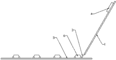
Fig. 3 is the user mode synoptic diagram of handheld circuit board test fixture shown in Figure 1.
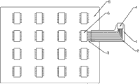
Fig. 4 is the vertical view of Fig. 3.
Fig. 5 is the front view of handheld circuit board test fixture second embodiment of the present invention.
Fig. 6 is the left view of Fig. 5.
Fig. 7 is the user mode synoptic diagram of handheld circuit board test fixture shown in Figure 5.
Fig. 8 is the vertical view of Fig. 7.
Fig. 9 is Fig. 1, a handheld circuit board test fixture shown in Figure 5 view when simultaneously the pin that is positioned at tested components and parts two sides being tested.
Figure 10 is the vertical view of Fig. 9.
Figure 11 is the structural representation of test probe.
Embodiment
Below in conjunction with drawings and Examples the present invention is described in further detail.
Fig. 1, shown in Figure 2, handheld circuit board test fixture of the present invention comprise that one is convenient to the strip web joint 1 that staff grips, and the middle part of strip web joint 1 is made and is easy to the shape that staff grips.Left upper end at described web joint is fixed with connector 4, the outside side end face of described connector 4 is provided with tester connecting line jack, and the tester connecting line jack of connector 4 has outwards guaranteed that the flat stube cable that connects between connector 4 and the tester can not bring inconvenience to the tester.Embodiment is that described connector 4 left end face are provided with tester connecting line jack preferably, the right flank relative with described tester connecting line jack is provided with the wiring pin that is electrically connected with described tester connecting line jack, and this structure is suitable for the anchor clamps that the right hand grips when being test.Be fixed with the test probe 3 that stretches out web joint in the lower end of web joint 1.Described test probe 3 is a plurality of, the parallel web joint 1 that is distributed in, and its spacing is corresponding with tested components and parts lead pin pitch.Shown in Figure 11, described test probe comprises that one is fixed in the conductive shell 33 of described web joint and is installed on syringe needle moving up and down 31 in the described housing inner chamber, described syringe needle upper end is connected with the needle interior wall top by power spring 32, and stretch out outside the described housing described syringe needle 31 lower ends.Web joint 1 is provided with multiple conducting wires 2 and is connected respectively with each pin of described connector 4 with the conductive shell 33 with each test probe 3.
Fig. 3, shown in Figure 4, when using anchor clamps shown in Figure 1 that circuit-under-test plate 5 is tested, at first use flat stube cable that connector 4 is connected with tester, grip the middle part of web joint 1 then with the right hand, right side one array of pins with the tested components and parts 6 of test probe 3 alignings, and syringe needle 31 stung on the pin of tested components and parts 6, apply suitable power again, make the spring in the test probe 3 produce deformation, assurance has enough power to sting insullac on tested components and parts 6 pins, make the two good contact, finish whole clamping process thus.Restart tester operation test procedure, can test one by one the components and parts on the circuit-under-test plate 56.Be convenient test, handheld circuit board test fixture of the present invention can be designed the anchor clamps of a plurality of specifications so that the quantity of test probe 3 and spacing and tested electronic devices and components 6 corresponding getting final product according to the number of pin of tested electronic devices and components 6 with spacing dissimilar electronic devices and components 6.
Fig. 5, handheld circuit board test fixture shown in Figure 6 and the difference of embodiment shown in Figure 1 are: described connector 4 is fixed in the upper right side of described web joint 1, and tester connecting line jack is positioned at its right end face of described connector 4.Present embodiment is a kind of suitable left-handed and anchor clamps that the left side pin of tested components and parts is tested.
Fig. 7, Figure 8 shows that the synoptic diagram that uses handheld test anchor clamps shown in Figure 5 the circuit-under-test plate to be carried out clamping.Utilize this anchor clamps, the tester need not turnover fixture when the left side pin of tested components and parts is tested, thereby has avoided the inconvenience that brings to the tester of reversing of the flat stube cable that switching process caused.
When Fig. 9 and Figure 10 are used for the anchor clamps of aforementioned two kinds of structures the circuit-under-test plate is tested the synoptic diagram of clamping.Test fixture shown in Figure 1 is used for the right one array of pins of tested components and parts is carried out clamping, test fixture shown in Figure 2 is used for the left side one array of pins of tested components and parts is carried out clamping, thus, can disposable a tested component testing be finished, thereby effectively improve testing efficiency.
Claims (6)
1. handheld circuit board test fixture, it is characterized in that comprising that one is convenient to web joint (1) that staff grips, is fixed in described web joint (1) and stretches out in the test probe (3) of this web joint and be fixed in the connector (4) on the described web joint (1), the lateral surface of described connector is provided with tester connecting line jack, the side relative with described tester connecting line jack is provided with the wiring pin that is electrically connected with described tester connecting line jack, is connected to lead (2) between described wiring pin and the described test probe (3); Described test probe comprises that one is fixed in the housing (33) of described web joint and is installed on syringe needle moving up and down (31) in the described housing inner chamber, described syringe needle upper end is connected with the needle interior wall top by spring (32), and stretch out outside the described housing described syringe needle (31) lower end.
2. handheld circuit board test fixture according to claim 1, it is characterized in that described web joint (1) is a rectangular plate, described connector (4) is fixed in the upper end of described web joint (1), and described test probe (3) is fixed in the lower end of described web joint (1).
3. handheld circuit board test fixture according to claim 2 is characterized in that described connector (4) is fixed in the left upper end of described web joint (1), and tester connecting line jack is positioned at the left end face of described connector (4).
4. handheld circuit board test fixture according to claim 2 is characterized in that described connector (4) is fixed in the upper right side of described web joint (1), and tester connecting line jack is positioned at its right end face of described connector (4).
5. according to claim 2,3 or 4 described handheld circuit board test fixtures, the middle part that it is characterized in that described strip web joint (1) is made and is easy to staff and grips shape.
6. handheld circuit board test fixture according to claim 1, it is characterized in that the parallel web joint (1) that is distributed in of described test probe (3), spacing between the described test probe is corresponding with tested components and parts lead pin pitch, and set each lead (2) is connected each test probe (3) each pin with described connector (4) respectively on web joint.
Priority Applications (1)
| Application Number | Priority Date | Filing Date | Title |
|---|---|---|---|
| CN2011101368322A CN102183681A (en) | 2011-05-25 | 2011-05-25 | Handheld circuit board test fixture |
Applications Claiming Priority (1)
| Application Number | Priority Date | Filing Date | Title |
|---|---|---|---|
| CN2011101368322A CN102183681A (en) | 2011-05-25 | 2011-05-25 | Handheld circuit board test fixture |
Publications (1)
| Publication Number | Publication Date |
|---|---|
| CN102183681A true CN102183681A (en) | 2011-09-14 |
Family
ID=44569888
Family Applications (1)
| Application Number | Title | Priority Date | Filing Date |
|---|---|---|---|
| CN2011101368322A Pending CN102183681A (en) | 2011-05-25 | 2011-05-25 | Handheld circuit board test fixture |
Country Status (1)
| Country | Link |
|---|---|
| CN (1) | CN102183681A (en) |
Cited By (3)
| Publication number | Priority date | Publication date | Assignee | Title |
|---|---|---|---|---|
| CN104090135A (en) * | 2014-06-26 | 2014-10-08 | 中国航天科工集团第三研究院第八三五七研究所 | Chip testing probe suitable for various pin tiny intervals |
| CN108051618A (en) * | 2017-11-28 | 2018-05-18 | 南京晨光集团有限责任公司 | A kind of frock clamp for circuit board testing |
| CN115267275A (en) * | 2022-09-30 | 2022-11-01 | 南通米乐为微电子科技有限公司 | Testing device, testing assembly and testing method for surface-mounted components |
Citations (4)
| Publication number | Priority date | Publication date | Assignee | Title |
|---|---|---|---|---|
| CN2725898Y (en) * | 2004-07-07 | 2005-09-14 | 曾家棠 | Adapting probe for measurer of printed circuitboard |
| CN201035042Y (en) * | 2007-03-29 | 2008-03-12 | 比亚迪股份有限公司 | Test arrangement for testing flexible circuit board electrical behavior |
| CN101697002A (en) * | 2009-10-16 | 2010-04-21 | 陈俊堂 | Low-resistance printed circuit board test device |
| CN202351345U (en) * | 2011-11-14 | 2012-07-25 | 福建联迪商用设备有限公司 | Testing device for fine-pitch arranged pins on PCB (Printed Circuit Board) |
-
2011
- 2011-05-25 CN CN2011101368322A patent/CN102183681A/en active Pending
Patent Citations (4)
| Publication number | Priority date | Publication date | Assignee | Title |
|---|---|---|---|---|
| CN2725898Y (en) * | 2004-07-07 | 2005-09-14 | 曾家棠 | Adapting probe for measurer of printed circuitboard |
| CN201035042Y (en) * | 2007-03-29 | 2008-03-12 | 比亚迪股份有限公司 | Test arrangement for testing flexible circuit board electrical behavior |
| CN101697002A (en) * | 2009-10-16 | 2010-04-21 | 陈俊堂 | Low-resistance printed circuit board test device |
| CN202351345U (en) * | 2011-11-14 | 2012-07-25 | 福建联迪商用设备有限公司 | Testing device for fine-pitch arranged pins on PCB (Printed Circuit Board) |
Cited By (3)
| Publication number | Priority date | Publication date | Assignee | Title |
|---|---|---|---|---|
| CN104090135A (en) * | 2014-06-26 | 2014-10-08 | 中国航天科工集团第三研究院第八三五七研究所 | Chip testing probe suitable for various pin tiny intervals |
| CN108051618A (en) * | 2017-11-28 | 2018-05-18 | 南京晨光集团有限责任公司 | A kind of frock clamp for circuit board testing |
| CN115267275A (en) * | 2022-09-30 | 2022-11-01 | 南通米乐为微电子科技有限公司 | Testing device, testing assembly and testing method for surface-mounted components |
Similar Documents
| Publication | Publication Date | Title |
|---|---|---|
| US9291645B2 (en) | Probe unit | |
| TWM431990U (en) | Improvement of driving circuit board structure for LED lamp connection | |
| CN104914278B (en) | Test fixture for single layer capacitance | |
| TW201504631A (en) | High frequency probe card for probing photoelectric device | |
| CN102183681A (en) | Handheld circuit board test fixture | |
| CN2838082Y (en) | Wiring harness terminal insertion positioning detector | |
| CN101526577A (en) | Connector detection tool | |
| CN109459655B (en) | Conduction testing device | |
| CN204560009U (en) | Printed circuit board measuring point draws keyset | |
| CN202471641U (en) | Water quality detection system and probe thereof | |
| CN202494690U (en) | Testing tool and testing instrument | |
| CN104820116A (en) | Connecting device suitable for low-temperature electrical test and using method thereof | |
| CN101656365A (en) | Conveniently tested electric connector | |
| CN202057750U (en) | Detection device used for detecting electrical property of flat cable | |
| CN201126472Y (en) | Table-connecting rack structure for fast connecting ammeter, terminal interface | |
| CN208607300U (en) | Micro electronmechanical attitude measurement element batch-testing device | |
| CN203720212U (en) | Interface box system used for chip testing | |
| CN104991092B (en) | Second protection testing terminal arranges adapter | |
| CN202794249U (en) | Test probe for surface-mount discrete semiconductor device | |
| CN203811771U (en) | Chip test device | |
| CN203551733U (en) | Light emitting diode detection device | |
| CN208125876U (en) | A kind of triode Kelvin test suite | |
| CN203365488U (en) | Probe type connector detection apparatus | |
| CN111856339A (en) | Pogo Pin detection device | |
| CN204302320U (en) | A kind of test DUT board |
Legal Events
| Date | Code | Title | Description |
|---|---|---|---|
| C06 | Publication | ||
| PB01 | Publication | ||
| C10 | Entry into substantive examination | ||
| SE01 | Entry into force of request for substantive examination | ||
| C12 | Rejection of a patent application after its publication | ||
| RJ01 | Rejection of invention patent application after publication |
Application publication date: 20110914 |